Article

Effect of Porous Medium and Copper Heat Sink on Cooling of Heat-Generating Element

1
Laboratory on Convective Heat and Mass Transfer, Tomsk State University, 634050 Tomsk, Russia
2
Department of Mathematics, Davangere University, Shivagangothri, Davangere 577007, India
3
Department of Mathematics, Guru Nanak Dev University, Amritsar 143005, India
*
Author to whom correspondence should be addressed.
Energies 2020, 13(10), 2538; https://doi.org/10.3390/en13102538
Submission received: 20 April 2020 / Revised: 7 May 2020 / Accepted: 13 May 2020 / Published: 17 May 2020
(This article belongs to the Section J: Thermal Management)

Abstract

:
Cooling of heat-generating elements is a challenging problem in engineering. In this article, the transient free convection of a temperature-dependent viscosity liquid inside the porous cavity with copper radiator and the heat-generating element is studied using mathematical modeling techniques. The vertical and top walls of the chamber are kept at low constant temperature, while the bottom wall is kept adiabatic. The working fluid is a heat-conducting liquid with temperature-dependent viscosity. A mathematical model is developed based on dimensionless stream function, vorticity, and temperature variables. The governing properties are the variable viscosity, geometric parameters of the radiator, and size of thermally insulated strip on vertical surfaces of the cavity. The effect of these parameters on the energy transport and circulation patterns are analyzed numerically. Based on the numerical results obtained, recommendations are given on the optimal values of the governing parameters for the effective operation of the cooling system. It is shown that the optimal number of radiator fins for the cooling system configuration under consideration is 3. In addition, the thermal insulation of the vertical walls and the increased thickness of the radiator fins have a negative effect on the operation of the cooling system.

Graphical Abstract

1. Introduction

Development of modern engineering fields is related to heat transfer enhancement in creation of effective cooling systems. Well-timed heat removal from the heat-generating elements allows an increase in the operation life of the whole electronic apparatus. For an intensification of the energy removal from such elements, it is possible to use the porous insertions combined with heat sinks and special heat transfer fluids. For such systems, natural convective heat transfer can be considered as a main heat removal mechanism [1,2,3,4]. It should be noted that the impact of the thermophysical properties of the working fluid on energy transport has an important value in convection problems [5,6]. Often the dependence of viscosity on ambient temperature, fluid density or fluid pressure is considered [6,7,8]. Moreover, there are many problems of natural convection with other assumptions including the magnetic field influence, heat transfer with phase changes, nanoparticles impact [9,10,11,12,13,14,15,16]. The results of numerical simulation of convective heat transfer simulation taking into account the effect of magnetic fields are shown in [9,10,11,12]. In addition, the convective heat transfer with phase changes is studied in [13] and the influence of solid nanoparticles on convective energy transport is shown in [9,10,11,12,13,14]. In [15,16], Singh et al., investigated the effect of time periodically varying temperatures of the vertical boundaries on the onset of natural convection with regard to bicritical states concerning periodic heat and mass exchange between the walls and the fluid.
A substantial interest was presented in the numerical analysis of free, natural, and mixed convection in the case of the chamber with porous layers. Sadeghi et al. [17] studied a three-dimensional two-phase heat transfer in porous cubical cavity using the lattice Boltzmann simulations. The authors discussed the effect of dimensionless parameters such as the Weber number, the Froude number, the porosity, the Reynolds number, and the density ratio on the convective flow within the chamber. It was shown that an increase in the Reynolds number and porosity leads to an increase in the rate of liquid penetration into the porous material. Zhao et al. [18] studied 2D free convection of liquid-saturated Darcy-Brinkman porous chamber with the local heat and pollutant sinks on the bottom border. The energy transport across the isotropic porous material was analyzed with the help of streamlines, isotherms, and distribution of overall Nusselt and Sherwood numbers. Impact of the governing characteristics such as Rayleigh number, Darcy number on the heat and mass transport is also reported. Maghsoudi and Siavashi [19] investigated the mixed convection of copper–water nanoliquid within porous chamber with moving walls. The optimization of pores dimensions of the porous layer in various parts of the cavity to maximize the Nusselt number was done. As a result, the optimized heterogeneous porous medium was obtained. Nield and Kuznetsov [20] studied analytically the energy and mass transport in a porous zone having a nanoliquid. Darcy model was used for description of the porous medium. They showed that the inclusion of a Brinkman term in the underlying mathematical model did not have a major effect. Hooman and Gurgeni [21] studied forced convection of the liquid with variable viscosity within a porous cavity. The influence of viscosity change on the allocation temperature and velocity was analyzed. The investigation was performed over different values of the permeability of the porous material. Seth et al. [22] studied time-dependent free convection with a conducting, incompressible, energy absorbing and chemically reacting liquid over a movable vertical wall via a porous layer. The solutions of governing equations were obtained using the Laplace transforms technology. Rashidi et al. [23] demonstrated a review of the problems about usage of porous medium in heat exchangers. The application of porous materials with high magnitudes of porosity was mentioned a promising way to improve the energy transport in thermal systems. Thus, the use of porous inserts such as metal foam is a good way to enhance heat removal from heaters.
Many studies related to the numerical and experimental simulation of fluid flow and heat transfer in the presence of a heat sink and energy-generating units in different practical cases were published [24,25,26]. For example, Smolka et al. [27] presented computational and experimental data of the energy transport in electrical transformers. They showed different problems of the natural convection with many complications. The governing equations of both electromagnetic and computational fluid dynamics (CFD) models were demonstrated. The numerical calculations were verified with the help of the high temperature transformer experiments over nominal parameters for dry-type transformers. Zhao et al. [28] investigated computationally and experimentally the water flow for two different channel geometries with radiator and heater. ANSYS Icepak 14.0 (ANSYS, Inc. Canonsburg PA 15317 USA) was used for mathematical simulation. The results showed that the geometry of channels inside a radiator played the main role in the working of this cooling system. Moreover, the data of numerical modeling had a good concordance with experimental data. The numerical investigation of energy and mass transport in a copper porous micro-channel radiator was performed by Qiu et al., in [29]. The obtained data demonstrates that the geometry parameters such as porosity, pore diameter, length, width, and height of heat sink have an essential influence on the heat transfer in the considered area. Bar-Cohen and Iyengar [30] conducted a study on optimization of air-cooled thermal sinks applied for the cooling of electronic equipment. Their results show that to get the high thermal performance, it is desirable to use the heat sink with high side ratio fins. Zhao and Tan [31] have given a nice review including the recent research about thermoelectric cooling system in the industry. It is shown that the study on the cooling systems of different types has a good prospect in the future and such systems are important for the heat transfer strengthening.
Thus, the research of the cooling systems with various complications such as porous insertions, energy sources, heat sinks, nanofluids or “smart” heat transfer fluids is becoming the more important direction due to the development of different engineering areas. It should be noted that mathematical simulation in this case is a good way for cooling system optimization.
Considering the above literature review, it can be noted that interest in heat transfer problems has been very high at the current time. In addition, there are few theoretical studies on modeling of water cooling systems for heat-generating units under the impacts of different parameters, including porous medium, temperature dependence of the fluid viscosity, volumetric heat generation of the inner body, and thermal properties of analyzed materials. The objective of the present research is to examine the thermogravitational convection of viscous, Newtonian, heat-conducting liquid in a porous closed chamber with a heat-generating element and a copper heat sink under the influence of external isothermal cooling. The Brinkman approach has been employed for the transport processes description within the porous medium. Such investigation can be useful for the development of passive cooling systems based on the natural convective energy transport taking into account the effects of porous layers and finned heat sink. Moreover, they used finned heat sink and porous material allow to increase the heat removal surface that is widely employed in various engineering applications. For the present study, such techniques have been combined to examine this joint influence. They performed a brief review of the published papers and to the authors’ best knowledge, there are not published studies on the considered problem.

2. Basic Equations

The physical formulation of the considered problem is shown in Figure 1. The length and the width of the square cavity is L. The considered system includes the liquid-saturated porous material, the finned copper radiator and the thermally-generating silicon unit placed on the lower border of the chamber. The top wall and the parts of vertical walls have fixed cooling temperature Tc, while the bottom wall and the rest parts of vertical walls of a length H1 are adiabatic. The dimensional length of the fins of the radiator is H. The dimensional width of the fins of the radiator is w. A heat-generating and heat-conducting element with internal volumetric heat flux Q is located in the middle of the bottom wall. The heater has a constant size (0.1 × 0.12). The number of fins n has been varied to understand the influence of this parameter. It is believed in the research that the viscosity of the working liquid depends on temperature [5,32], and the circulation within the cavity is laminar. The liquid is energy-conducting, viscous, and Newtonian. Further, it is assumed that the Boussinesq approach is applicable. In the present simulation we use the local thermal equilibrium approach (the temperature of the liquid phase is similar to the temperature of the porous matrix everywhere within the porous layer).
The porous insertion has been described using the Brinkman–extended Darcy approximation. Employing the above assumptions, the system of governing equations for simulation of the unsteady laminar 2-D problem can be studied in dimensional variables [32,33]:
  • inside the porous layer
    u ¯ x ¯ + v ¯ y ¯ = 0
    ρ f ( 1 ε u ¯ t + u ¯ ε 2 u ¯ x ¯ + v ¯ ε 2 u ¯ y ¯ ) = p x ¯ + 2 ε x ¯ ( μ ¯ ( T ) u ¯ x ¯ ) + 1 ε y ¯ [ μ ¯ ( T ) ( u ¯ y ¯ + v ¯ x ¯ ) ] μ ¯ ( T ) K u ¯
    ρ f ( 1 ε v ¯ t + u ¯ ε 2 v ¯ x ¯ + v ¯ ε 2 v ¯ y ¯ ) = p y ¯ + 2 ε y ¯ ( μ ¯ ( T ) v ¯ y ¯ ) + 1 ε x ¯ [ μ ¯ ( T ) ( u ¯ y ¯ + v ¯ x ¯ ) ] μ ¯ ( T ) K v ¯ + ρ g β ( T T c )
    η T t + u ¯ T x ¯ + v ¯ T y ¯ = λ p m ( ρ c ) f ( 2 T x ¯ 2 + 2 T y ¯ 2 )
  • inside the copper heat sink
    ( ρ c ) r T t = λ r ( 2 T x ¯ 2 + 2 T y ¯ 2 )
  • inside the heat-generating element
    ( ρ c ) h s T t = λ h s ( 2 T x ¯ 2 + 2 T y ¯ 2 ) + Q
The non-dimensional variables such as vorticity ( ω ¯ = v ¯ x ¯ u ¯ y ¯ ) and stream function ( u ¯ = ψ ¯ y ¯ , v ¯ = ψ ¯ x ¯ ) have been used for solution to Equations (1)–(6). In this case, dimensional pressure p has been excluded from Equations (2) and (3). Dimensionless characteristics were considered as
x = x ¯ / L ,   y = y ¯ / L ,   h = H / L ,   h 1 = H 1 / L ,   δ = w / L ,   τ = t g β Δ T / L ,   θ = ( T T c ) / Δ T ,   μ = μ ¯ / μ 0 , u = u ¯ / g β Δ T L ,   v = v ¯ / g β Δ T L ,   ψ = ψ ¯ / g β Δ T L 3 ,   ω = ω ¯ L / g β Δ T
Thus, the final version of the non-dimensional governing equations of natural convection (1)–(6) can be written in the following way:
  • inside the porous insertion
    2 ψ x 2 + 2 ψ y 2 = ω
    ε ω τ + u ω x + v ω y = ε Pr R a ( 2 ( μ ω ) x 2 + 2 ( μ ω ) y 2 ε μ ω D a ) + ε 2 θ x + + 2 ε Pr R a [ ε u 2 D a μ y ε v 2 D a μ x + 2 μ x 2 u y 2 μ y 2 v x + 2 μ x y ( v y u x ) ]
    η θ τ + u θ x + v θ y = α p m / α f R a Pr ( 2 θ x 2 + 2 θ y 2 )
  • inside the copper heat sink
    θ τ = α r / α f R a Pr ( 2 θ x 2 + 2 θ y 2 )
  • inside the heat-generating element
    θ τ = α h s / α f R a Pr ( 2 θ x 2 + 2 θ y 2 + O s )
Here α f = λ f ( ρ c p ) f ,   α r = λ r ( ρ c p ) r ,   α h s = λ h s ( ρ c p ) h s are the overall thermal diffusivities of each component. Table 1 illustrates thermophysical characteristics of the considered materials.
The initial and boundary conditions for the developed system (7)–(11) are considered in the form:
  τ = 0 : ψ = ω = θ = 0 for   0 x 1   and   0 y 1   τ > 0 : ψ = 0 ,   ω = 2 ψ x 2 ,   θ x = 0 for   x = 0 ,   x = 1 ,   0 y h 1 ψ = 0 ,   ω = 2 ψ x 2 ,   θ = 0 for   x = 0 ,   x = 1 ,   h 1 y 1 ψ = 0 ,   ω = 2 ψ y 2 ,   θ = 0 for   y = 1   and   0 x 1 θ y = 0 for   y = 0   and   0 < x < 1 }
at   heat   source   surface :   { θ h s = θ r λ h s λ r θ h s n = θ r n at   horizontal   porous-radiator   interfaces :   { θ p m = θ r λ p m λ r θ p m y = θ r y at   vertical   porous-radiator   interface :   { θ p m = θ r λ p m λ r θ p m x = θ r x }

3. Numerical Technique

Numerical solution of the system of differential Equations (7)–(11) with appropriate relations (12) and (13) has been obtained using the finite difference technique [32,33,34]. The diffusive and convective terms have been approximated by the difference schemes of the second order accuracy, while the first-order difference scheme has been added for the time derivatives. At the same time, the monotonic scheme of Samarskii has been applied for the convective members of equations, whereas the central differences have been taken for diffusive members. The difference Poisson Equation (7) has been solved by the successive over relaxation technique. The difference equations for the energy and vorticity have been worked out by the Samarskii locally one-dimensional scheme. Then the Thomas algorithm has been employed for the last step of equations solution. The proposed numerical method has been implemented using numerical code developed by means of C++ programming language (Microsoft Visual Studio, Redmond, WA, USA).
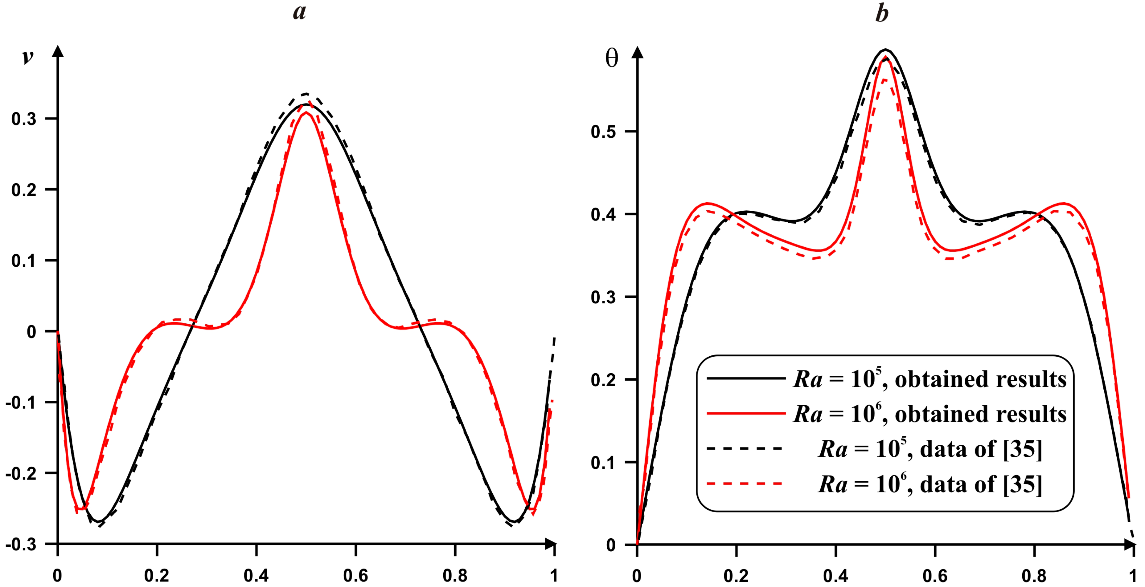
The developed computational procedure has been verified employing the numerical results of AlAmiri et al. [35]. This study deals with a problem of natural convection inside a closed square enclosure in the presence of a salient isothermal heater on the center of the bottom wall. The horizontal borders of the cavity are adiabatic, while the vertical walls have a constant low temperature. Figure 2 shows a good concordance with the results of AlAmiri et al. [35] for Pr = 0.71 and different values of Ra.
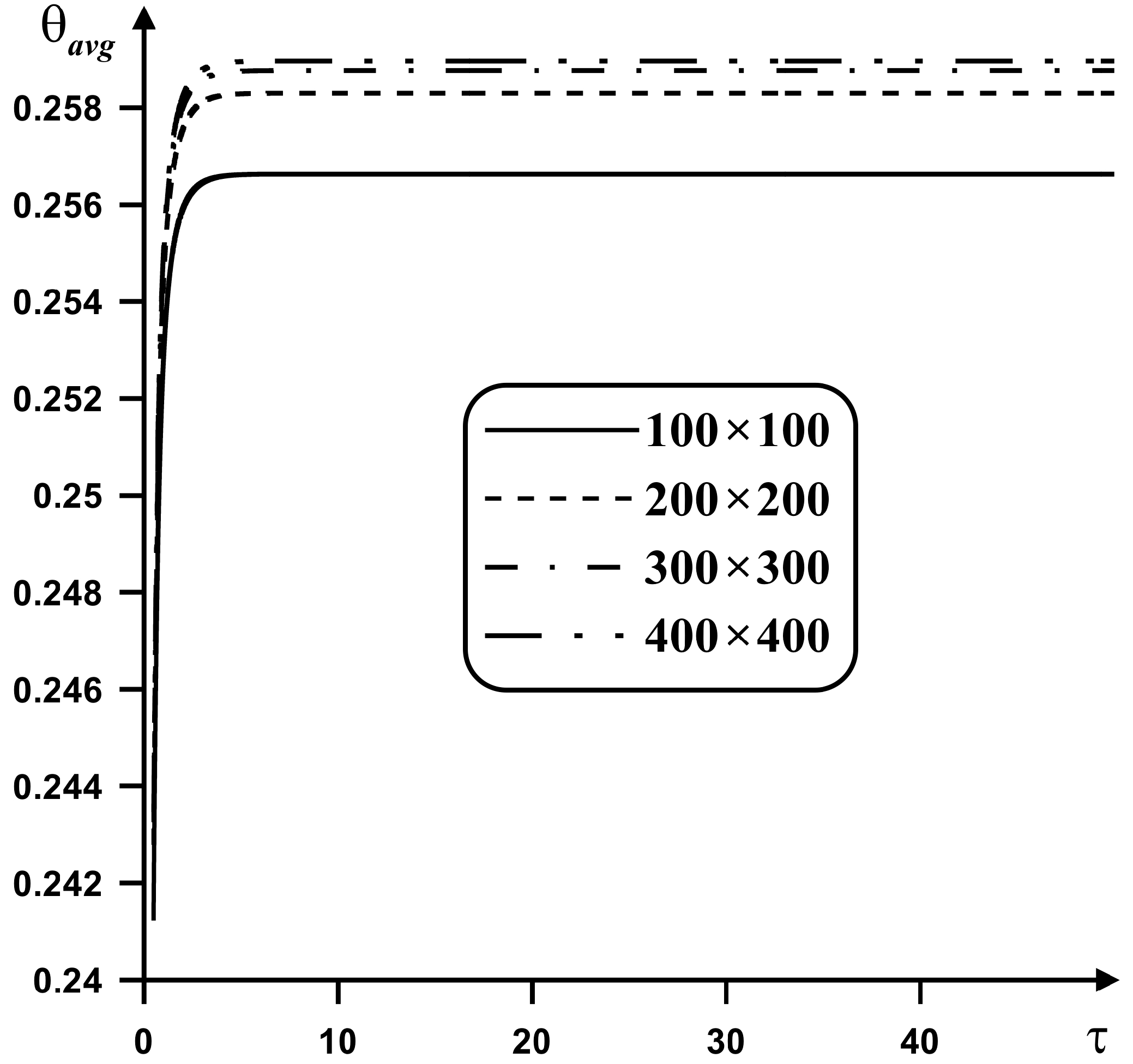
The grid independence test has been done for Pr = 7.0, Ra = 105, ζ = 1, Da = 10−2, Os = 25, h = 0.2, h1 = 0.15, n = 3, δ = 0.12 for the domain of interest presented in Figure 1. The mathematical model (7)‒(11) has been discretized using the different grids, namely, 100 × 100, 200 × 200, 300 × 300, and 400 × 400. The obtained data of computations with different numbers of nodes are presented in Figure 3. To have the accurate numerical results the uniform mesh of 200 × 200 points is acceptable.

4. Results

Calculation of the problem of natural convection (7)–(12) has been performed at following ranges of dimensionless parameters: Ra = 105, Pr = 7.0, h = 0.2, Os = 25.0, ε = 0.9, Da = 10–2, ζ = 0.0, 1.0, h1 = 0.0–1.0, δ = 0.06–0.24, n = 1–5, τ = 0.0–50.0. The simulation results are demonstrated in Figure 4, Figure 5, Figure 6, Figure 7, Figure 8 and Figure 9. Values of dimensionless characteristics including the Rayleigh number, Prandtl number, Darcy number, Ostrogradsky number and porosity of the porous insertion have been selected to demonstrate the moderate influence of the considered processes. It should be noted that effects of the fins number, fins thickness, and length of the adiabatic part on the vertical walls have been studied.
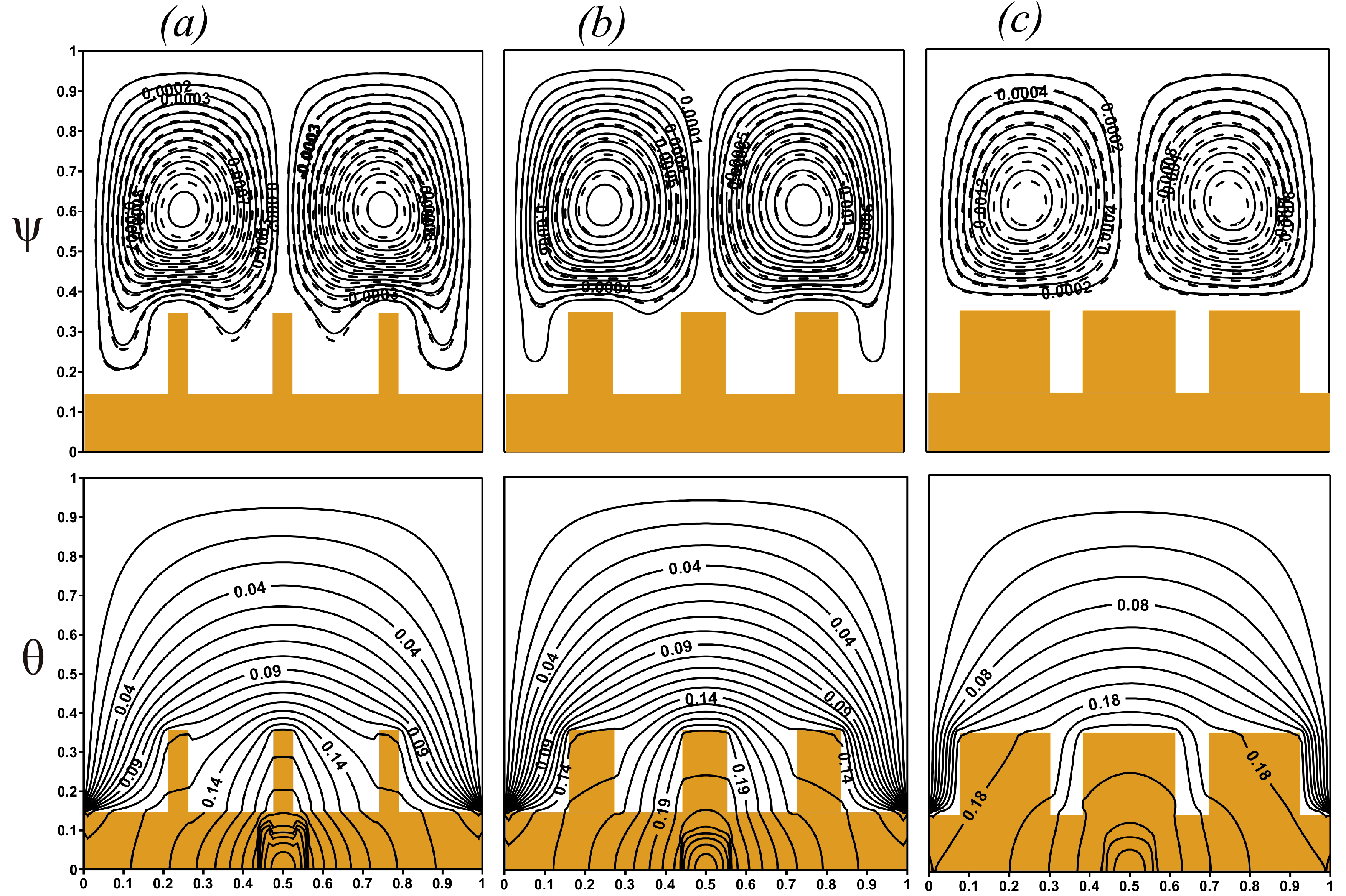
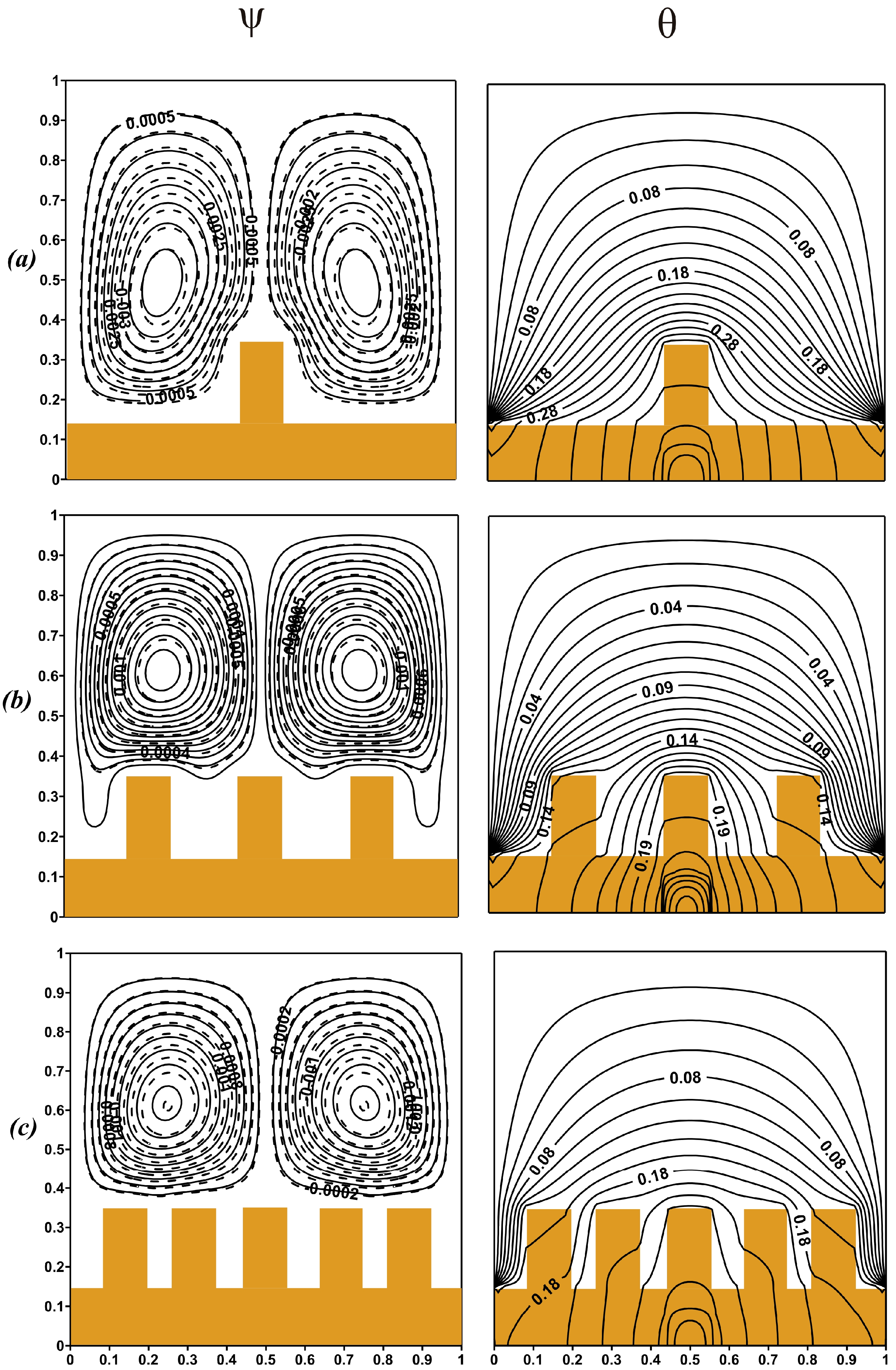
Figure 4 shows the streamlines and isotherms for various fins thickness and different values of the viscosity variation parameter at h1 = 0.15. The radiator material has the high value of the heat conductivity and provides uniform energy removal from the heater. The heat conduction is strengthened by the influence of the porous zone within the cavity. The fluid motion is evenly distributed for each case of the fins thickness, but the formed circulations are very weak owing to huge resistance from the solid matrix of the porous material. For small values of δ (Figure 4a,b), the convective flow is developed between the fins also, while for high magnitude of this parameter the convective energy transport is weakened, and convective cells are located above the fins. Such displacement of the circulation zones leads to a reduction of the heat removal area contacting with circulated liquid and as a result the energy transport strength is reduced. It can be assumed that the porous layer in the cavity has a significant impact on energy removal and its displacement by the radiator fins inhibits the cooling process of the heat-generating element. A weak rise of the flow strength in the cavity is monitored during the moving from a fluid with constant viscosity (solid lines) to a fluid with variable viscosity (dashed lines), whereas the isotherms are unchanged.
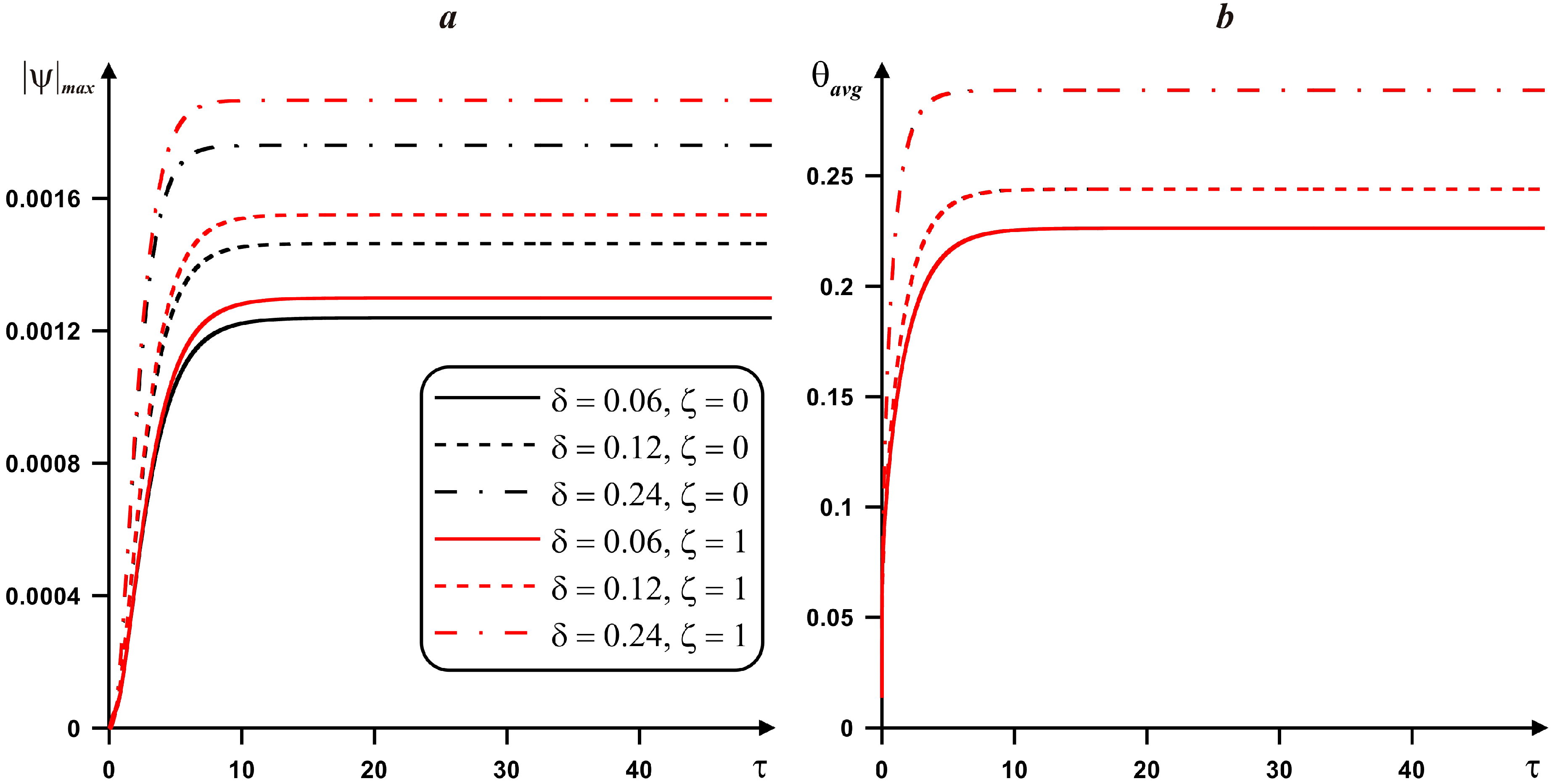
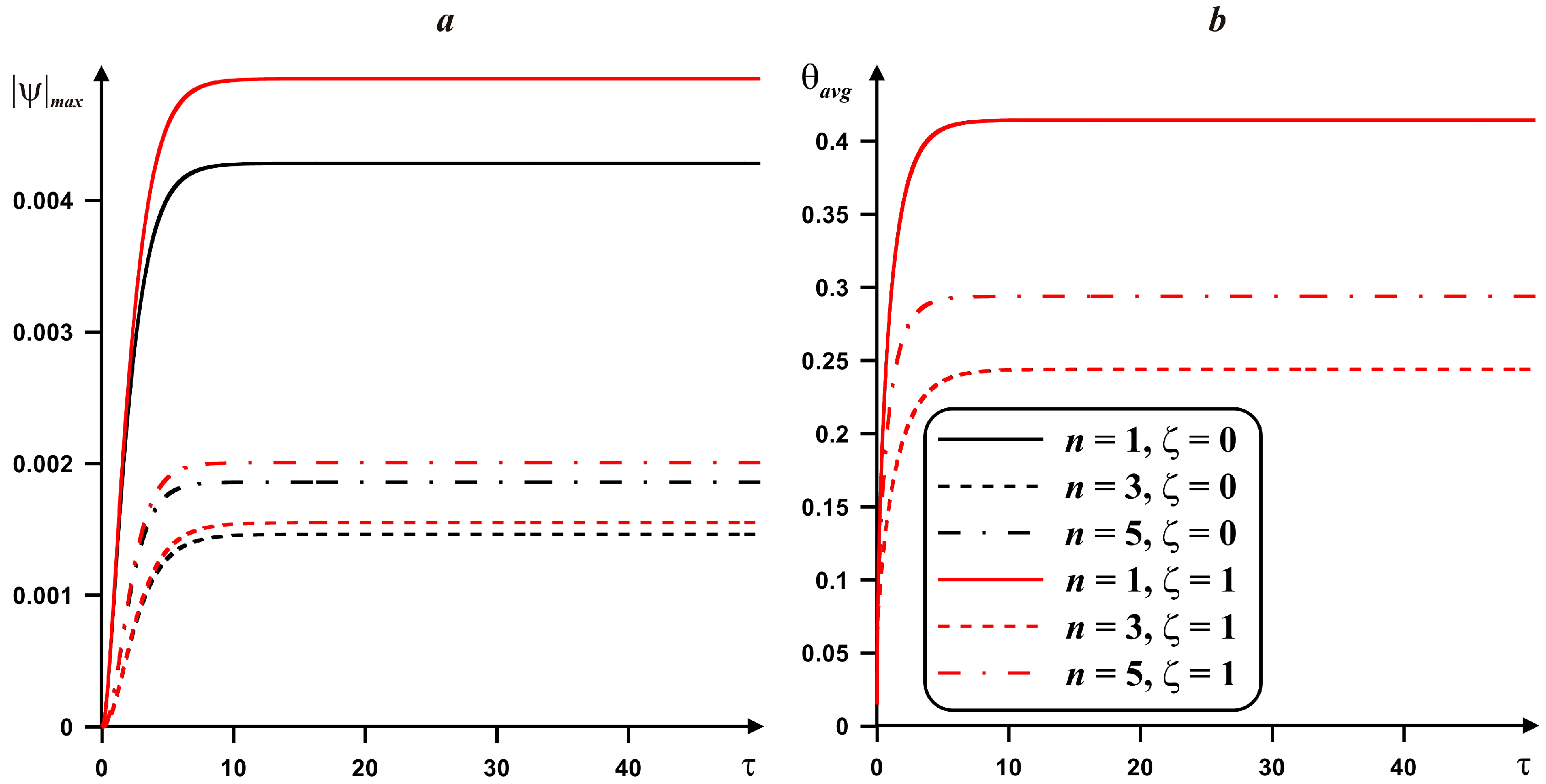
These results are confirmed by the data in Figure 5, which reflects variations of circulation intensity and average heater temperature for h1 = 0.15 and different values of ζ and fins thickness. An appearance of steady state of the liquid circulation process and energy transfer is observed by the time τ = 50. A low fins thickness (δ = 0.06) displays the minimum values of liquid circulation intensity within the chamber and the average heater temperature is low also. A rise of δ results in an increase in the liquid circulation strength and the average heater temperature. In addition, the working fluid with variable viscosity (ζ = 1) makes this effect more noticeable. It should be noted that in this case when the area of the heat sink increases, the contribution of heat conduction to the overall energy transport within the chamber is raised. Thus, an increment of the fins thickness affects adversely the characteristics of the cooling system. The considered system is not usual, taking into account a combination of finned heat sink and a porous material with ε = 0.9, Da = 10−2. Such combination does not allow to enhance the convective circulation within the chamber due to a presence of solid matrix of the porous material, and as a result the heat conduction can be considered as a major energy transport mechanism. Therefore, an increase in fins thickness leads to a rise of the average heater temperature.
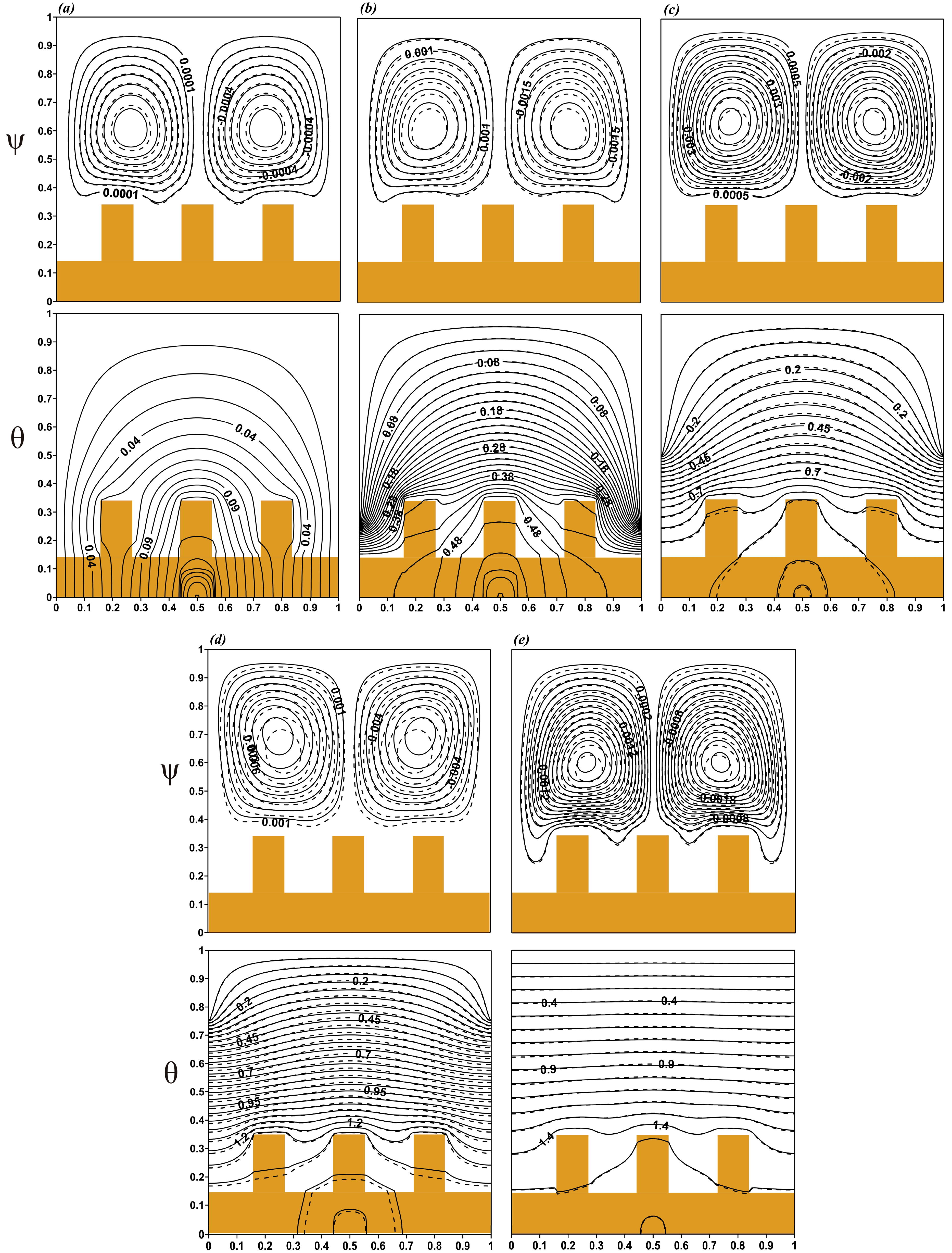
The effect of fins number on the streamlines and isotherms for h1 = 0.15, ζ = 0, and ζ = 1 is presented in Figure 6 and Figure 7. Figure 6 demonstrates the isolines of stream function and temperature for different viscosity variation parameter ζ values and fins numbers n. It should be noted that for n = 1 and 3 the thickness of fins was 0.12, while for n = 5 the fins width was considered equal to 0.11. This parameter was selected for the symmetrical arrangement of fins relative to the energy source. The heater was located under the middle fin. It can be seen by the location of the isotherms inside the radiator. Parameter n illustrates a great impact on the thermal transmission within the region. A rise of the fins number illustrates a non-monotonic behaviour of the average temperature within the enclosure. Namely, for n = 3 one can find more essential cooling of the cavity, where temperature is less in comparison with other analyzed cases.
The flow in the cavity is suppressed with n; convective motions are displaced into part of the cavity without a heat sink (Figure 6c). It can be explained by the incrementing influence of thermal conduction of the porous medium between fins and the cooling effect from the vertical walls. It is interesting to note that the flow circulation strength is decreased with a rise of n from 1 until 3, but for a growth of n between 3 and 5 the flow rate is increased slightly. Such nature can be explained by the blockage effect when fins reduce the fluid circulation region and this effect is clearly presented for n = 5. Further, the use of a fluid with variable viscosity (dashed lines) leads to a slight increase in convective flow strength. Such effect for problems of the natural convection has been shown in other works [32,36].
Figure 7 illustrates the combined influence of viscosity change parameter ζ and fins number n on circulation intensity and average heater temperature for h1 = 0.15. The results from Figure 6 are verified by the data of Figure 7. The maximum value of the fluid flow rate is achieved at ζ = 1 for each value of n (Figure 7a). Moreover, a rise in n has a non-monotonic influence on the liquid circulation strength (Figure 7a) and average temperature of heater (Figure 7b). For example, in the case of n = 3 one can find more essential reduction of the average heater temperature and less intensive circulation within the chamber, while for n = 5 the mean temperature of the heated element and the motion strength are increased. Such obtained results make someone think that there are some differences between the present data and results shown in Figure 5. However, a rise of the fins number is not the same like a growth of the fins thickness due to a presence of the interfin space where the porous material is located and as a result the working fluid can circulate within this interfin space. Thus, results characterize a presence of optimal number of fins for effective heat removal from the element. Therefore, parameter n is the effective way to intensify the heat dissipation from the heated element within the considered cavity.
The effect of the size of the adiabatic part of vertical walls h1 on the streamlines and isotherms for ζ = 0 and ζ = 1 is shown in Figure 8. In any cases, a steady flow with the weak downstream and the upstream motions is formed within the cavity. For the case without adiabatic part at vertical walls (Figure 8a), the heat flux from the source is quickly removed due to the cooling effect of the borders. When h1 = 0.25 the flow structure changes slightly, isolines are formed at the boundaries of the adiabatic area (Figure 8b). The difference between fluid flow with constant and variable viscosity is becoming more significant. The convection of variable viscosity liquid is more intense. In this case, the temperature in the cavity increases due to the decrease in the areas of cold temperature on the vertical walls. With a further increase in h1 (Figure 8c,d), the flow motions for the case of a liquid with varying viscosity (dashed lines) are suppressed significantly, while the isotherms tend to the top cooled wall. When the vertical borders are adiabatic completely, (Figure 8e) isolines of temperature in the cavity are distributed horizontally. In addition, the porous medium warms up evenly. Convective flows in the chamber are suppressed by thermal conduction. Thus, the thermal insulation of the vertical boundaries of the cavity does not have a positive effect on the efficiency of the cooling system. Such analysis allows understanding an influence of adiabatic part on the heat removal intensity. Moreover, a quarter reduction of the cooling part characterizes an essential augmentation of the mean heater temperature in comparison with whole cooling vertical walls.
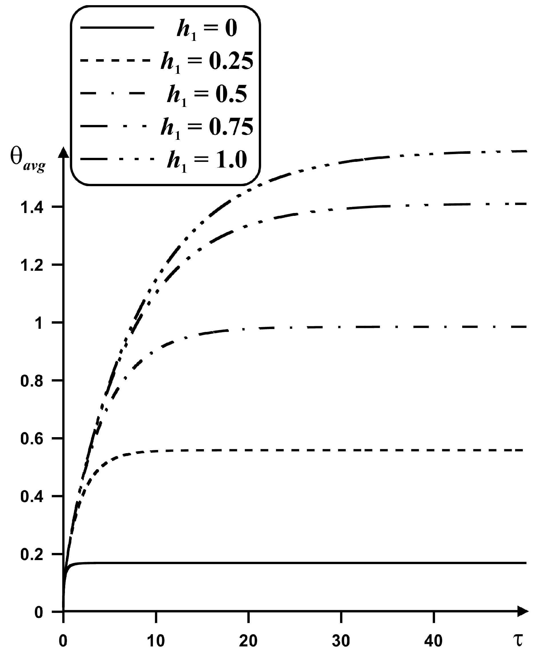
Figure 9 reflects an influence of the height of the insulation part of vertical walls h1 on the average heater temperature for ζ = 0. As it has been noted above, a rise of the thermal insulation area at the vertical walls results in a rise of the mean heater temperature. Moreover, a growth of h1 illustrates a rise of time for the steady mode. Using these data, it is possible to define the size for the cooling zones to achieve the fixed thermal flux removal from the heated element.

5. Conclusions

The process of thermogravitational convection of the liquid with a temperature-dependent viscosity in a closed porous two-dimensional enclosure having a heat-conducting and heat-generated element with a copper heat sink on the lower adiabatic boundary of the cavity has been examined numerically with the help of non-dimensional stream function, vorticity and temperature variables. A numerical simulation has been conducted in a broad range of the governing parameters such as geometry characteristics of the heat sink, viscosity, and time. The distribution of isolines and integral characteristics of heat transfer has been received. It has been demonstrated that geometry characteristics of the heat sink play the main role in the process. For example, a rise of the thickness of the radiator fins from 0.06 to 0.24 characterizes an increment of the average heater temperature up to 28%, while a growth of the length of the adiabatic sections on the vertical walls from 0 to 1 leads to an increase in the temperature within the energy source at about by ten times. A rise in the fins number has the non-monotonic effect, namely, the convective motion strength and average heater temperature are reduced for a rise on n from 1 to 3 (namely, the liquid circulation rate decreases at about 63% and average heater temperature reduces at about 41%), while these average parameters are increased when n rises from 3 until 5 (namely, the liquid circulation rate increases at about 27% and average heater temperature rises at about 21%). Therefore, the fins number n = 3 can be considered as an optimal value of fins number characterizing low heater temperature. Taking into account the temperature dependent viscosity with exponential law one can find a physical nature for the results of mathematical modeling with intensification of the convective flows within the cavity. The cooling system with a copper heat sink is a good way for management of heat removal from the energy source. As a rule, such systems have a high thermal conductivity and heat capacity which provide effective heat removing.

Author Contributions

Conceptualization, M.A. and M.S.; methodology, M.S.; software, M.A.; validation, M.A.; formal analysis, M.A. and M.S; investigation, M.A. and M.S; writing—original draft preparation, M.A. and M.S.; writing—review and editing, M.A., M.S., U.S.M., and J.S.; supervision, M.S.; project administration, M.S. All authors have read and agreed to the published version of the manuscript.

Funding

This work was supported by the Grants Council (under the President of the Russian Federation), Grant No. MD-821.2019.8.

Acknowledgments

Authors thank the respected reviewers for their constructive comments which clearly enhanced the quality of the manuscript.

Conflicts of Interest

The authors declare no conflict of interest.

Abbreviations

The following abbreviations are used in this manuscript:
cheat capacity [J⋅kg−1⋅K−1]
Da = K/L2Darcy number [–]
ggravity acceleration [m⋅s−2]
Hdimensional height of the radiator fins [m]
H1dimensional height of the adiabatic part of vertical walls [m]
hdimensionless height of the radiator fins [–]
h1dimensionless height of the adiabatic part of vertical walls [–]
Kporous layer permeability [m2]
Lsize of the enclosure [m]
nnumber of fins [–]
Os = QL2/(λhsΔT)Ostrogradsky number [–]
pstatic pressure [Pa]
Pr = μ0/(ρα)Prandtl number [–]
Qvolumetric heat flux [W⋅m−3]
Ra = ρgβΔTL3/(αμ0)Rayleigh number [–]
Tdimensional temperature [K]
Tccold wall temperature [K]
tdimensional time [s]
u ¯ ,   v ¯ dimensional velocity components [m⋅s−1]
u, vdimensionless velocity components [–]
x ¯ ,   y ¯ dimensional coordinates [m]
x, ydimensionless coordinates [–]
wdimensional width of the fins [m]
Greek symbols
αheat diffusivity [m2⋅s−1]
βthermal expansion coefficient [K−1]
δnon-dimensional fins width [–]
ΔT = TrefTctemperature difference [K]
εporosity of the porous insertion [–]
η = ε + ( 1 ε ) ( ρ c ) s / ( ρ c ) f overall specific heat ratio [–]
θnon-dimensional temperature [–]
λthermal conductivity [W⋅m−1⋅K−1]
μ ¯ ( T ) = μ 0 exp [ ζ ( T T c ) / Δ T ] variable dynamic viscosity [Pa⋅s]
μ0dynamic viscosity at reference temperature [Pa⋅s]
μ = exp(−ζθ)non-dimensional dynamic viscosity [–]
ζviscosity changeable parameter [–]
ρfluid density [kg⋅m−3]
τnon-dimensional time [–]
ψ ¯ stream function [m2⋅s−1]
ψnon-dimensional stream function [–]
ω ¯ vorticity [s−1]
ωnon-dimensional vorticity [–]
Subscripts
ccold
effeffective
ffluid
hsheat source
pmporous material
rradiator
refreference
ssolid porous matrix

References

  1. Bairi, A.; Zarco-Pernia, E.; De Maria, J.M.G. A review on natural convection in enclosures for engineering applications. The particular case of the parallelogrammic diode cavity. Appl. Therm. Eng. 2014, 63, 304–322. [Google Scholar] [CrossRef]
  2. Florio, L.; Harnoy, A. Combination technique for improving natural convection cooling in electronics. Int. J. Therm. Sci. 2007, 46, 76–92. [Google Scholar] [CrossRef]
  3. Zhang, K.; Li, M.-J.; Wang, F.-L.; He, Y.-L. Experimental and numerical investigation of natural convection heat transfer of W-type fin arrays. Int. J. Heat Mass Transf. 2020, 152, 119315. [Google Scholar] [CrossRef]
  4. Adhikari, R.C.; Wood, D.H.; Pahlevani, M. Optimizing rectangular fins for natural convection cooling using CFD. Therm. Sci. Eng. Prog. 2020, 17, 100484. [Google Scholar] [CrossRef]
  5. Hyun, J.M.; Lee, J.W. Transient natural convection in a square cavity of a fluid with temperature-dependent viscosity. Int. J. Heat Fluid Flow 1988, 9, 278–285. [Google Scholar] [CrossRef]
  6. He, B.; Lu, S.; Gao, D.; Chen, W.; Lin, F. Lattice Boltzmann simulation of double diffusive natural convection in heterogeneously porous media of a fluid with temperature-dependent viscosity. Chin. J. Phys. 2020, 63, 186–200. [Google Scholar] [CrossRef]
  7. De Castro, C.A.N.; Li, S.F.Y.; Nagashima, A.; Trengove, R.; Wakeham, W.A. Standard Reference Data for the Thermal Conductivity of Liquids. J. Phys. Chem. Ref. Data 1986, 15, 1073. [Google Scholar] [CrossRef] [Green Version]
  8. Charitidou, E.; Molidou, C.; Assael, M.J. The thermal conductivity and viscosity of benzene. Int. J. Thermophys. 1988, 9, 37–45. [Google Scholar] [CrossRef]
  9. Hasona, W.; El-Shekhipy, A.; Ibrahim, M. Combined effects of magnetohydrodynamic and temperature dependent viscosity on peristaltic flow of Jeffrey nanofluid through a porous medium: Applications to oil refinement. Int. J. Heat Mass Transf. 2018, 126, 700–714. [Google Scholar] [CrossRef]
  10. Abbasi, F.M.; Shanakhat, I.; Shehzad, S. Entropy generation analysis for peristalsis of nanofluid with temperature dependent viscosity and Hall effects. J. Magn. Magn. Mater. 2019, 474, 434–441. [Google Scholar] [CrossRef]
  11. Tlili, I.; Bhatti, M.; Hamad, S.M.; Barzinjy, A.A.; Sheikholeslami, M.; Shafee, A.; Nguyen, T.K.; Ali, J.A. Macroscopic modeling for convection of Hybrid nanofluid with magnetic effects. Phys. A Stat. Mech. Appl. 2019, 534, 122136. [Google Scholar] [CrossRef]
  12. Dogonchi, A.; Seyyedi, S.M.; Hashemi-Tilehnoee, M.; Chamkha, A.J.; Ganji, D. Investigation of natural convection of magnetic nanofluid in an enclosure with a porous medium considering Brownian motion. Case Stud. Therm. Eng. 2019, 14, 100502. [Google Scholar] [CrossRef]
  13. Ghalambaz, M.; Chamkha, A.J.; Wen, D. Natural convective flow and heat transfer of Nano-Encapsulated Phase Change Materials (NEPCMs) in a cavity. Int. J. Heat Mass Transf. 2019, 138, 738–749. [Google Scholar] [CrossRef]
  14. Zadeh, S.M.H.; Sabour, M.; Sazgar, S.; Ghalambaz, M. Free convection flow and heat transfer of nanofluids in a cavity with conjugate solid triangular blocks: Employing Buongiorno’s mathematical model. Phys. A Stat. Mech. Appl. 2020, 538, 122826. [Google Scholar] [CrossRef]
  15. Singh, J.; Bajaj, R. Stability of temperature modulated convection in a vertical fluid-layer. Appl. Math. Model. 2018, 61, 408–420. [Google Scholar] [CrossRef]
  16. Singh, J.; Kaur, P.; Bajaj, R. Bicritical states in a vertical layer of fluid under two frequency temperature modulation. Phys. Rev. E 2020, 101, 023109. [Google Scholar] [CrossRef]
  17. Sadeghi, R.; Shadloo, M.S.; Hopp-Hirschler, M.; Hadjadj, A.; Nieken, U. Three-dimensional lattice Boltzmann simulations of high density ratio two-phase flows in porous media. Comput. Math. Appl. 2018, 75, 2445–2465. [Google Scholar] [CrossRef]
  18. Zhao, F.-Y.; Liu, D.; Tang, G.-F. Natural convection in an enclosure with localized heating and salting from below. Int. J. Heat Mass Transf. 2008, 51, 2889–2904. [Google Scholar] [CrossRef]
  19. Maghsoudi, P.; Siavashi, M. Application of nanofluid and optimization of pore size arrangement of heterogeneous porous media to enhance mixed convection inside a two-sided lid-driven cavity. J. Therm. Anal. Calorim. 2018, 135, 947–961. [Google Scholar] [CrossRef]
  20. Nield, D.A.; Kuznetsov, A. Thermal instability in a porous medium layer saturated by a nanofluid. Int. J. Heat Mass Transf. 2009, 52, 5796–5801. [Google Scholar] [CrossRef]
  21. Hooman, K.; Gurgenci, H. Effects of Temperature-Dependent Viscosity on Forced Convection Inside a Porous Medium. Transp. Porous Media 2008, 75, 249–267. [Google Scholar] [CrossRef]
  22. Seth, G.; Hussain, S.; Sarkar, S. Hydromagnetic natural convection flow with heat and mass transfer of a chemically reacting and heat absorbing fluid past an accelerated moving vertical plate with ramped temperature and ramped surface concentration through a porous medium. J. Egypt. Math. Soc. 2015, 23, 197–207. [Google Scholar] [CrossRef] [Green Version]
  23. Rashidi, S.; Kashefi, M.H.; Kimc, K.C.; Samimi-Abianeh, O. Potentials of porous materials for energy management in heat exchangers—A comprehensive review. Appl. Energy 2019, 243, 206–232. [Google Scholar] [CrossRef]
  24. Ahmed, H.E.; Salman, B.; Kherbeet, A.; Ahmed, M. Optimization of thermal design of heat sinks: A review. Int. J. Heat Mass Transf. 2018, 118, 129–153. [Google Scholar] [CrossRef]
  25. Zheng, X.; Qi, Z. A comprehensive review of offset strip fin and its applications. Appl. Therm. Eng. 2018, 139, 61–75. [Google Scholar] [CrossRef]
  26. Alihosseini, Y.; Targhi, M.Z.; Heyhat, M.M.; Ghorbani, N. Effect of a micro heat sink geometric design on thermo-hydraulic performance: A review. Appl. Therm. Eng. 2020, 170, 114974. [Google Scholar] [CrossRef]
  27. Smolka, J.; Biro, O.; Nowak, A. Numerical Simulation and Experimental Validation of Coupled Flow, Heat Transfer and Electromagnetic Problems in Electrical Transformers. Arch. Comput. Methods Eng. 2009, 16, 319–355. [Google Scholar] [CrossRef]
  28. Zhao, H.; Li, B.; Wang, W.; Hu, Y.; Wang, Y. Water cooling radiator for solid state power supply in fast-axial-flow CO2 laser. Front. Optoelectron. 2016, 9, 585–591. [Google Scholar] [CrossRef]
  29. Qiu, T.; Wen, D.; Hong, W.; Liu, Y. Heat transfer performance of a porous copper micro-channel heat sink. J. Therm. Anal. Calorim. 2019, 139, 1453–1462. [Google Scholar] [CrossRef]
  30. Bar-Cohen, A.; Iyengar, M. Design and optimization of air-cooled heat sinks for sustainable development. IEEE Trans. Compon. Packag. Technol. 2002, 25, 584–591. [Google Scholar] [CrossRef]
  31. Zhao, D.; Tan, G. A review of thermoelectric cooling: Materials, modeling and applications. Appl. Therm. Eng. 2014, 66, 15–24. [Google Scholar] [CrossRef]
  32. Astanina, M.S.; Sheremet, M.; Umavathi, J. Unsteady natural convection in a partially porous cavity having a heat-generating source using local thermal non-equilibrium model. Int. J. Numer. Methods Heat Fluid Flow 2019, 29, 1902–1919. [Google Scholar] [CrossRef]
  33. Mikhailenko, S.A.; Sheremet, M.A.; Mahian, O. Effects of uniform rotation and porous layer on free convection in an enclosure having local heat source. Int. J. Therm. Sci. 2019, 138, 276–284. [Google Scholar] [CrossRef]
  34. Bondareva, N.S.; Buonomo, B.; Manca, O.; Sheremet, M.A. Heat transfer performance of the finned nano-enhanced phase change material system under the inclination influence. Int. J. Heat Mass Transf. 2019, 135, 1063–1072. [Google Scholar] [CrossRef]
  35. AlAmiri, A.; Khanafer, K.; Pop, I. Buoyancy-induced flow and heat transfer in a partially divided square enclosure. Int. J. Heat Mass Transf. 2009, 52, 3818–3828. [Google Scholar] [CrossRef]
  36. Astanina, M.; Rashidi, M.M.; Sheremet, M.; Lorenzini, G. Effect of porous insertion on convective energy transport in a chamber filled with a temperature-dependent viscosity liquid in the presence of a heat source term. Int. J. Heat Mass Transf. 2019, 144, 118530. [Google Scholar] [CrossRef]
Figure 1. A scheme of the problem.
Energies 13 02538 g001
Figure 2. Velocity and temperature profiles in comparison with numerical data of AlAmiri et al. [35] for different Ra: (a) vertical velocity profiles; (b) temperature profiles.
Energies 13 02538 g002
Figure 3. Mesh sensitivity analysis of average heater temperature for Pr = 7.0, Ra = 105, ζ = 1, Da = 10–2, Os = 25, h = 0.2, δ = 0.12, n = 3, h1 = 0.15.
Energies 13 02538 g003
Figure 4. Isolines of ψ and θ for h1 = 0.15, ζ = 0 (solid lines), ζ = 1 (dashed lines): (a) δ = 0.06; (b) δ = 0.12; (c) δ = 0.24.
Energies 13 02538 g004
Figure 5. Variations of fluid flow rate and average heater temperature for h1 = 0.15 and different values of ζ and fins thickness: (a) fluid flow rate; (b) average heater temperature.
Energies 13 02538 g005
Figure 6. Isolines of ψ and θ for h1 = 0.15, ζ = 0 (solid lines), ζ = 1 (dashed lines): (a) n = 1; (b) n = 3; (c) n = 5.
Energies 13 02538 g006
Figure 7. Variations of fluid flow rate and average heater temperature for h1 = 0.15 and different magnitudes of ζ and n: (a) fluid flow rate; (b) average heater temperature.
Energies 13 02538 g007
Figure 8. Isolines of ψ and θ for ζ = 0 (solid lines), ζ = 1 (dashed lines) and various values of h1: (a) h1 = 0.0; (b) h1 = 0.25; (c) h1 = 0.5; (d) h1 = 0.75; (e) h1 = 1.0.
Energies 13 02538 g008
Figure 9. Variations of average heater temperature for ζ = 0 and various values of h1.
Energies 13 02538 g009
Table 1. Characteristics of materials.
Characteristics of Materialsρ, kg/m3c, J/(kg⋅K)λ, W/(m⋅K)
Fluid (water)997.141790.613
Solid structure (aluminum foam)2700897205
Heat sink (copper)8920385401
Heat-generating element (silicon)2330710150