Abstract
Low voltage direct current (LVDC) microgrid systems have many advantages over low voltage alternating current (LVAC) systems. Furthermore, LVDC microgrids are growing in use because they are easy to link to distributed energy resources (DER) and energy storage systems (ESS), etc. Currently, IT system LVDC microgrids are widely used in direct current (DC) railways, hospitals, photovoltaic (PV) systems, and so on. When a ground fault occurs in an IT system LVDC microgrid, the ground fault may not be detected because the fault current is very small and there is no current path. In this paper, ground fault detection is proposed using a hybrid method that comprises pulsation signal generator injection and detailed coefficients of discrete wavelet transform (DWT). The LVDC microgrid was modeled and simulated using power systems computer-aided design (PSCAD). In addition, the proposed hybrid method was implemented using MATLAB’s wave menu, a script m-file, and the PSCAD library. The proper threshold was selected and tested by fault resistance change and load variation. In order to verify the superiority of the proposed hybrid method, a comparative study with the conventional method was performed. The results of various simulations show that the proposed hybrid detection method has normal operation and accurately and rapidly detects ground faults.
Keywords:
detailed coefficient; DER; ESS; ground fault detection; hybrid method; LVDC microgrid; IT system; PSCAD 1. Introduction
Low voltage direct current (LVDC) microgrid systems have many advantages over low voltage alternating current (LVAC) systems that can increase power transfer capacity, reduce conversion losses, and eliminate power synchronization. Furthermore, LVDC microgrids are growing in use, and are more attractive, because they are easy to link to distributed energy resources (DER) and energy storage systems (ESS), etc. [1,2,3].
Currently, IT system LVDC microgrids are widely used in direct current (DC) railways, hospitals, photovoltaic (PV) systems, and so on because they include many benefits, such as higher efficiency and improved economics. When a ground fault occurs in an LVDC microgrid, the ground fault may not be detected because the fault current is very small and there is no current path. Moreover, if a ground fault is not cleared promptly, the ground fault will create a short circuit fault in the LVDC microgrid system, which will cause a fire hazard. In addition, the fault identification should be identified quickly for troubleshooting and maintenance [4,5,6,7].
In domestic studies in South Korea, development of a DC leakage current sensor for solar power generation system and of a ground fault detection method in unearthed low voltage DC distribution system using a probe unit was attempted [8,9]. The LVDC distribution system is being built on the South Korean island Geochado by Korea Electric Power Company (KEPCO). For this project, a ground fault detection system was imported from overseas [1,7,10]. In 2018, there was an analysis of IT grounding system protection devices applied to power converter systems (PCS) imported from overseas [10].
Studies from abroad include various publications on the detection of ground faults in IT system LVDC microgrids and ungrounded DC traction power systems [4,11,12]. Fault identification methods selected in ungrounded industrial systems use pulse generators to inject and apply high-frequency signals to faulty systems [6,11,13]. Bender and Asea Brown Boveri Ltd (ABB) implemented a method for identifying fault locations in AC and DC systems [14,15,16]. In addition, locating faults using traveling waves in AC and DC transmission lines were studied [17,18]. Spread spectrum time domain reflectometry (SSTDR) techniques, wavelets, and artificial neutral networks (ANNs) were used to try to detect and locate various faults in ungrounded PV systems and IT system DC microgrids. Meanwhile, discrete wavelet transform (DWT) has many advantages over discrete Fourier transform (DFT). Therefore, DWT is widely applied to fault diagnosis and signal analysis of power systems [19,20,21,22,23,24,25].
In this paper, as part of research into the development of high-speed circuit breakers for LVDC distribution systems [6], ground fault detection is proposed using a hybrid method in IT System LVDC microgrids. In order to detect the ground fault in an unearthed ground system, the hybrid method in which DWT is added to a conventional pulsating signal generator is designed and studied. The LVDC microgrid is modeled and simulated using power systems computer-aided design (PSCAD). In addition, the proposed method is implemented using MATLAB’s wave menu, a script m-file, and PSCAD library. The proper threshold is selected and tested by fault resistance change and load variation. In order to verify the superiority of the proposed method, a comparative study with the conventional method is performed. The results of various simulations show that the proposed hybrid detection method has normal operation and accurately and rapidly detects ground faults.
2. Hybrid Detection Method Using Pulsating Signal Generator and DWT
In an ungrounded LVDC microgrid, a pulsating signal generator is installed between each +pole and −pole to inject a pulse waveform. The injected pulse causes the voltage between the pole and the ground to oscillate. When a ground fault occurs, the pulsating signal generator can measure the current. Through the DWT analysis of the measured current (), a ground fault is judged when the detailed coefficient magnitude of the signal is larger than the threshold value.
2.1. Principle of the Pulsating Signal Generator
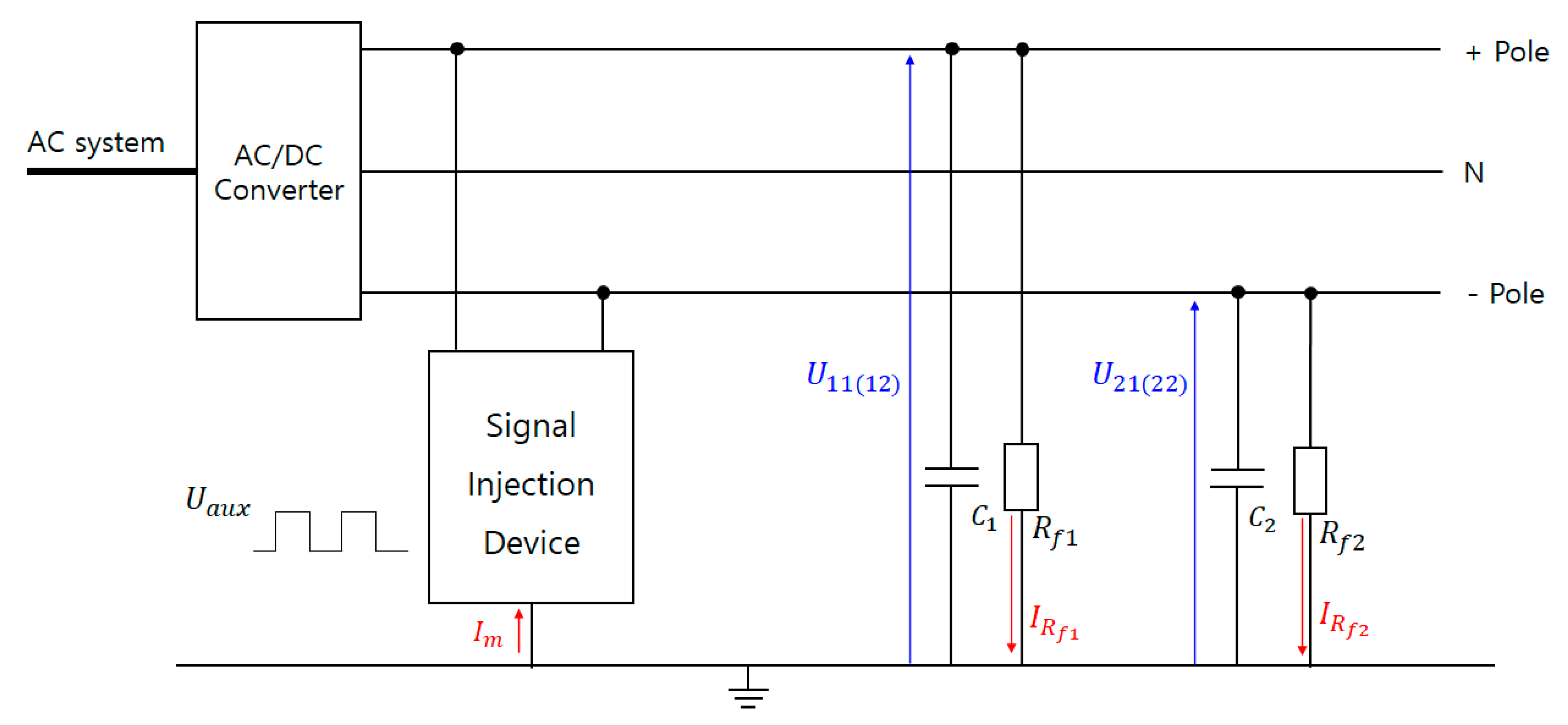
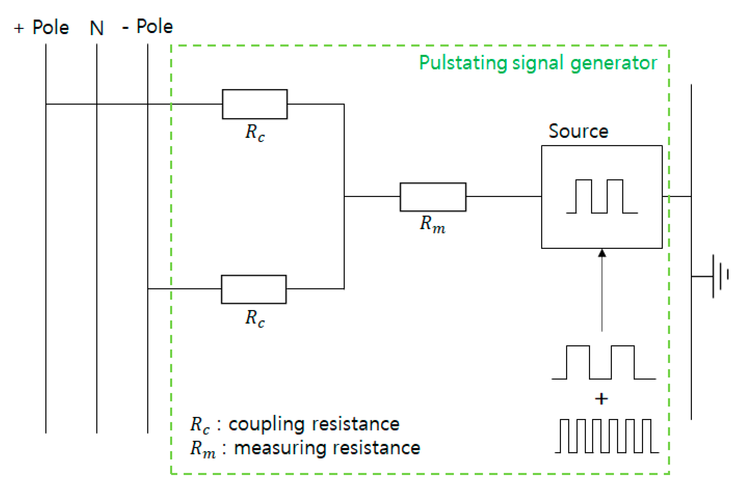
Figure 1 shows the principle of the pulsating signal generator. The pulsating signal generator injects a properly selected frequency between any point between the DC power line and ground. The test current driven by the power source flows to ground through all the insulation leakage resistance and capacitance. Using the measured current flowing through the measurement resistance in Figure 1, it is possible to determine the insulation and ground parameters. Thus, the steady state and the ground fault state can be identified [4,11,12,13,14].
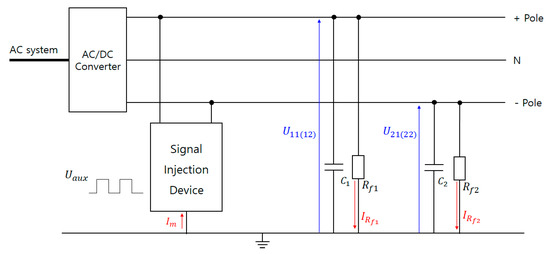
Figure 1.
Principle of the pulsating signal generator.
In Figure 1, is the injected voltage in pulsating signal generator; and are the steady state voltages of the respective poles toward the ground at the first half of each period; and are the steady state voltage in the latter half of the period; are the insulation capacitance; are the fault resistance in each pole; are the fault current in each pole; and N is the neutral line, respectively.
2.2. Discrete Wavelet Transform
The dilation parameter a and the translation can be described as and to discrete value, then the discrete wavelet function (DWF). is expressed as Equation (1).
where , , and j represent the scale factor, the shifting factor, and integer respectively.
Based on Equation (1), the basic principle of DWT can be shown in Equation (2).
where is the wavelet coefficient, which indicates the correlation between the wavelet and the original signal.
The decomposed sub-signal ( in every sub-band can be obtained by Equation (3).
where C is a signal independent constant.
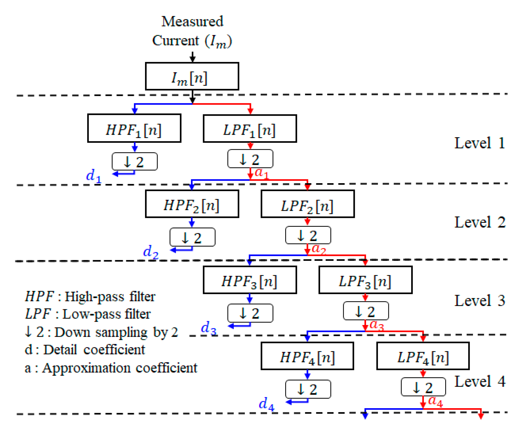
The most well-known implementation of DWT is the Mallat pyramid algorithm, which is multi-level decomposition (MLD) with digital filtering theory.
Figure 2 shows a wavelet decomposition tree representing MLD. In this study, was chosen as the original discrete signal. As shown in Figure 2, an original discrete leakage signal ([n]) was decomposed by passing through a low-pass filter (LPF) represented by and a high-pass filter (HPF) represented by simultaneously. The output of the HPF is called detail coefficients represented by d, while the output of the LPF is called approximation coefficients represented by a [11,20,21,22,23].
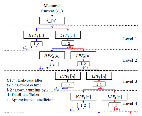
Figure 2.
Wavelet decomposition tree.
2.3. Ground Fault Detection Hybrid Method Using DWT Based on Pulsating Signal Generator
When analyzing signals in the power system, many transient components are included. The Daubechies mother function, which has excellent analysis ability, was selected as the most suitable one. The proposed ground fault detection hybrid method is based on the analysis of DWT of the measured current by injecting pulse signal into LVDC microgrid [6]. can be selected as a difference equation to facilitate real-time implementation through various simulation. The ground fault detection criteria formula, based on the detailed coefficients of the DWT (), can be expressed as Equation (4).
where is the detailed five coefficients at level 8 by MLD of mother wavelets using Daubechies.
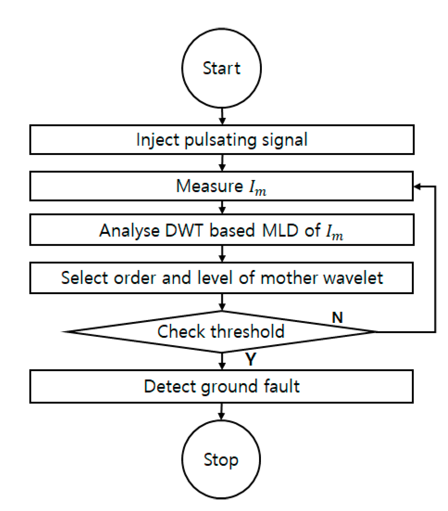
Figure 3 shows a flow chart of the proposed ground fault detection hybrid method. First, the proposed hybrid method injected a composite pulse signal by installing a pulsating signal generator between the +pole and the −pole in the LVDC microgrid system. We used the composite pulse signal, which was created by combining ±25 V, 1 Hz pulse signal and ±25 V, 10 Hz pulse signal. According to this composite pulse signal, the voltage magnitude between each pole and ground changed, and when a ground fault occurred, the current measured by the pulsating signal generator changed. Next, the measured current was analyzed through a DWT-based MLD. After selecting the optimal mother wavelet, the order and level of the Daubechies wavelet was selected through various simulations. Finally, the extracted value of was checked with the threshold value to determine whether or not the ground fault had occurred.
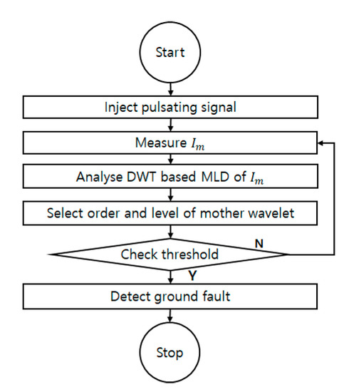
Figure 3.
Flowchart of the proposed ground fault detection hybrid method.
3. Modeling of LVDC Microgrid and Simulation of the Proposed Hybrid Method
3.1. Modeling of LVDC Microgrid
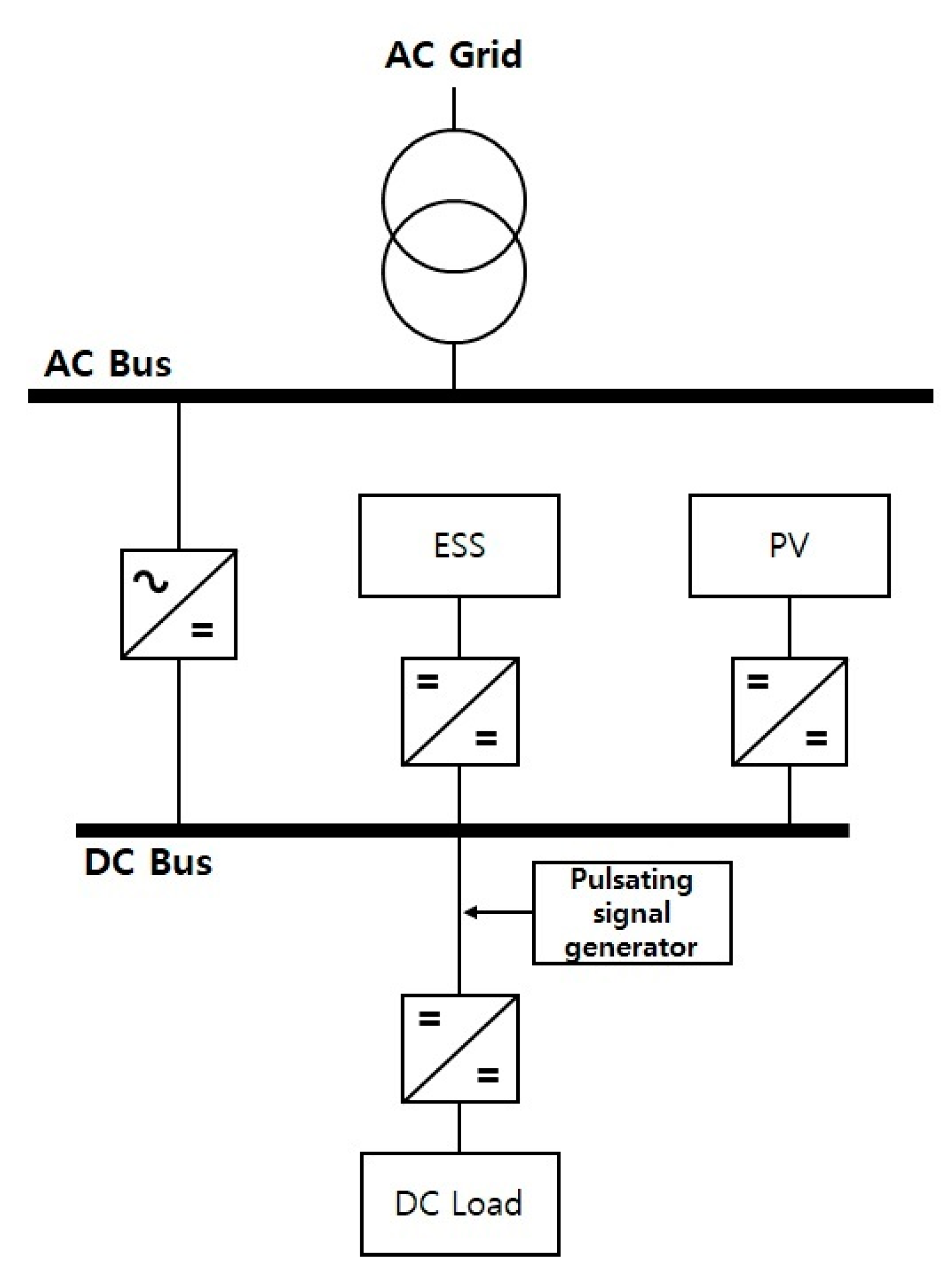
In South Korea, the bipolar voltage of LVDC microgrid is fixed to ±750 V. The power testbed was installed and tested at the KEPCO’s Gochang power testing center. Figure 4 shows a schematic diagram of an ungrounded LVDC microgrid of the Gochang power testing center. The ungrounded ±750 V LVDC microgrid had a converter station (500 kVA), PV (50 kW ×2), ESS (1 MWh), load (420 kW), etc.
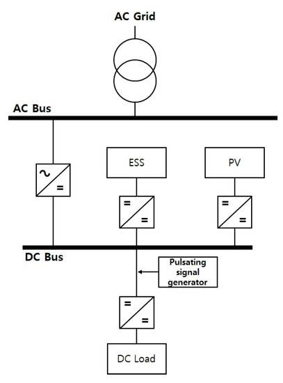
Figure 4.
Schematic diagram of an ungrounded low voltage direct current (LVDC) microgrid.
3.2. Performance Simulation of LVDC Microgrid
In this study, simulation scenario conditions for ungrounded LVDC grid were interconnected with the AC system at 0.25 s. PV operation was set to 1 s, ESS discharge operation to 2 s, and ESS charge operation to 6 s. The proposed hybrid ground detection method was applied to the DC load line. Ground fault, short-circuit fault, and load variation simulation were performed through PSCAD software to examine the proposed method. Additionally, performance evaluation of the proposed ground fault detection hybrid method was also performed using MATLAB.
PSCAD Modeling of Pulsating Signal Generator
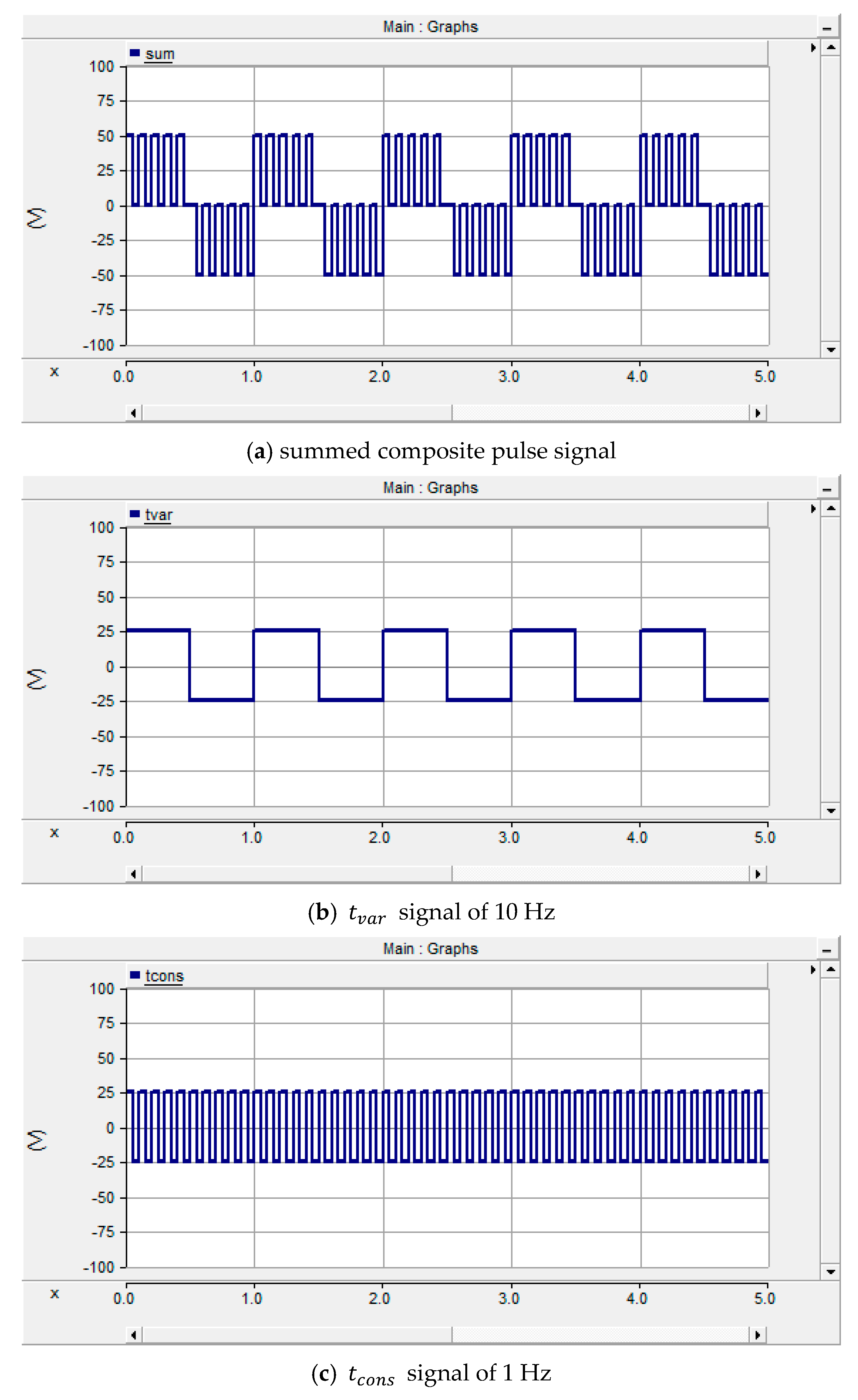
The schematic diagram of the pulsating signal generator shown in Figure 5 was modeled using PSCAD software. This composite pulse signal, which is injected into the ungrounded LVDC grid, is a rectangular pulse waveform that requires a sufficient period of time for stable detection signal measurements after transients due to capacitance between the +pole and the –pole. If the AC voltage measurement period () is set to approximately ( of the DC voltage measurement period (), then the AC voltage measurement period can be set to within , where is leakage capacitance and is the response value of an pulsating signal generator that measures the insulation values [14]. In this paper, a pulse with an amplitude of 50 V, a DC voltage measurement period of 1 s, and an AC voltage measurement period of 0.1 s were generated and applied to the LVDC grid, as shown in Figure 5. Figure 6 shows the injected pulse signal of the pulsating signal generator.
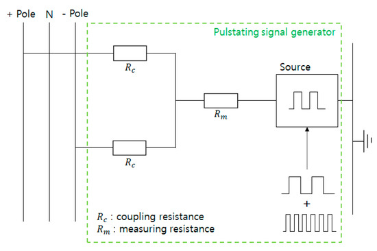
Figure 5.
Schematic diagram by power systems computer-aided design (PSCAD) modeling of the pulsating signal generator.
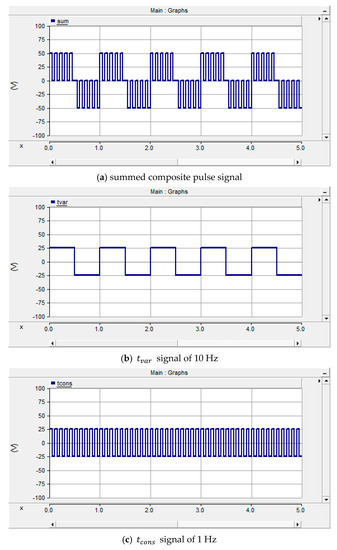
Figure 6.
The injected pulse signal of the pulsating signal generator.
3.3. Simulation and Test of Proposed Ground Detection Hybrid Method Using MATLAB
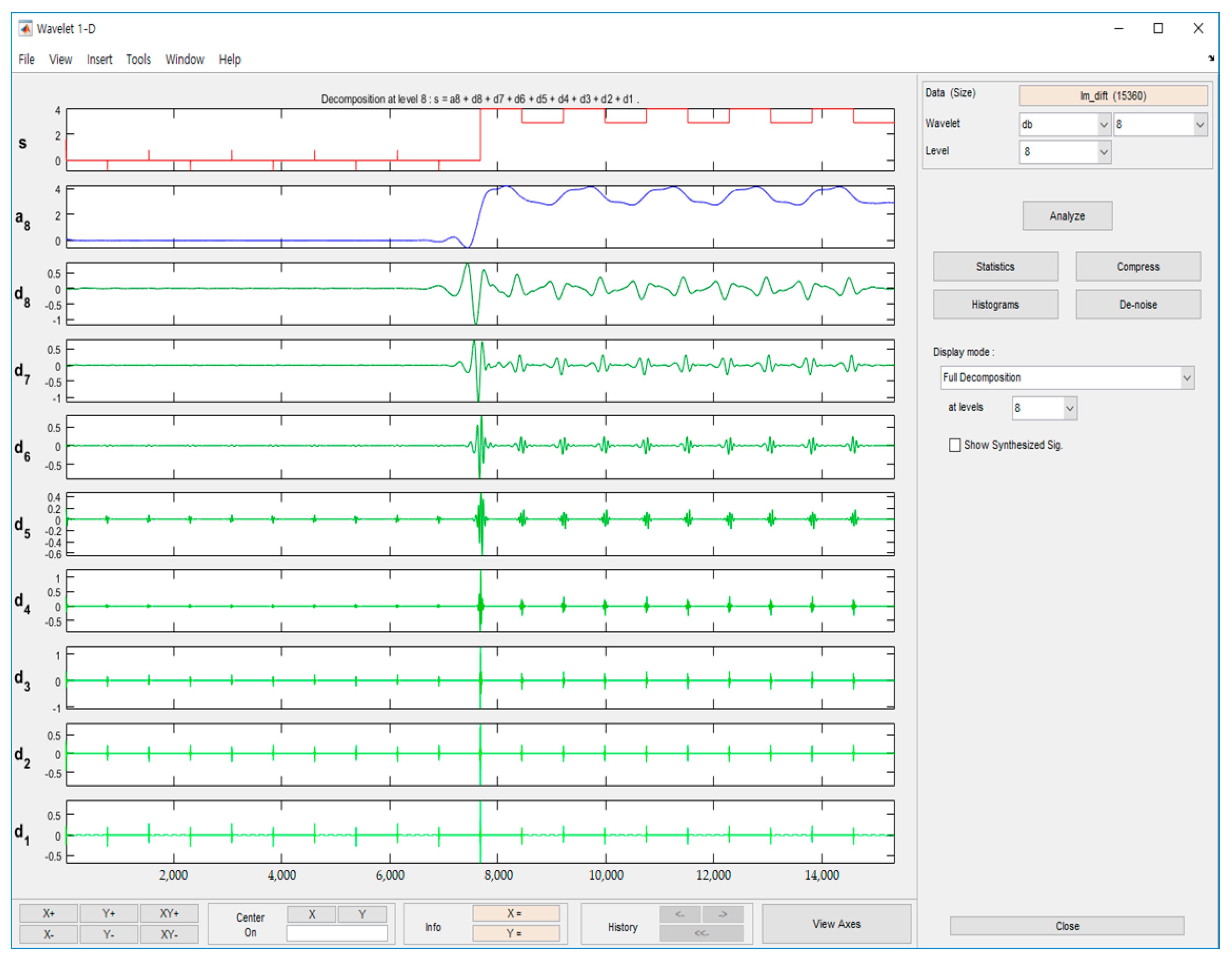
In order to verify the proposed ground fault detection hybrid method, we analyzed the DWT result signal by MLD using the wave menu of MATLAB. Daubechies was used as the mother wavelet function. The number of orders was varied from db1 to db8, the result signals from detail 1 to detail 8 were confirmed, and a total of 64 simulations were performed. Through various simulations, the optimal order and detail were obtained. Figure 7 shows the analysis of DWT at db8 of the measuring current as part of the analysis simulation. From Figure 7, it can be seen that the magnitude of the signal varied finely with the same period with each pulse waveform before and after the fault in the case of d1 to d4. In the case of d5 to d8, the signals before and after the fault were distinguished, and there was a slight fluctuation before the fault and a larger fluctuation after the fault. The magnitude at the fault inception point was about 0.8 mA. In the case of d5 to d8, the signals before and after the fault were distinguished. In the case of d5 to d8, it can be seen that the signals before and after the occurrence of the fault were distinguished. It varied slightly before the fault, and it fluctuated more greatly after the fault and became about 0.8 mA at the fault inception point.
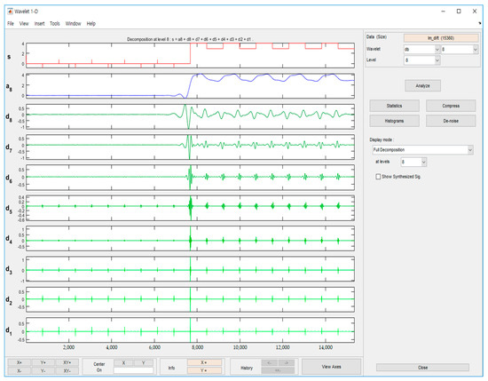
Figure 7.
The analysis of discrete wavelet transform (DWT) of measured current at db8.
As a result of MLD signal analysis using Daubechies, the detail 5 (d5) value of db8 was clearly shown before and after the fault, and the size was large at the fault point. In order to verify this, the test was carried out by varying the resistance from 1 to 500 kΩ and varying the load. In addition, the proposed hybrid method comprised the pulsation signal generator injection and the detailed coefficients of DWT, which provided the DWT through the internal library in PSCAD. To verify this, the D5 value of db8 was verified.
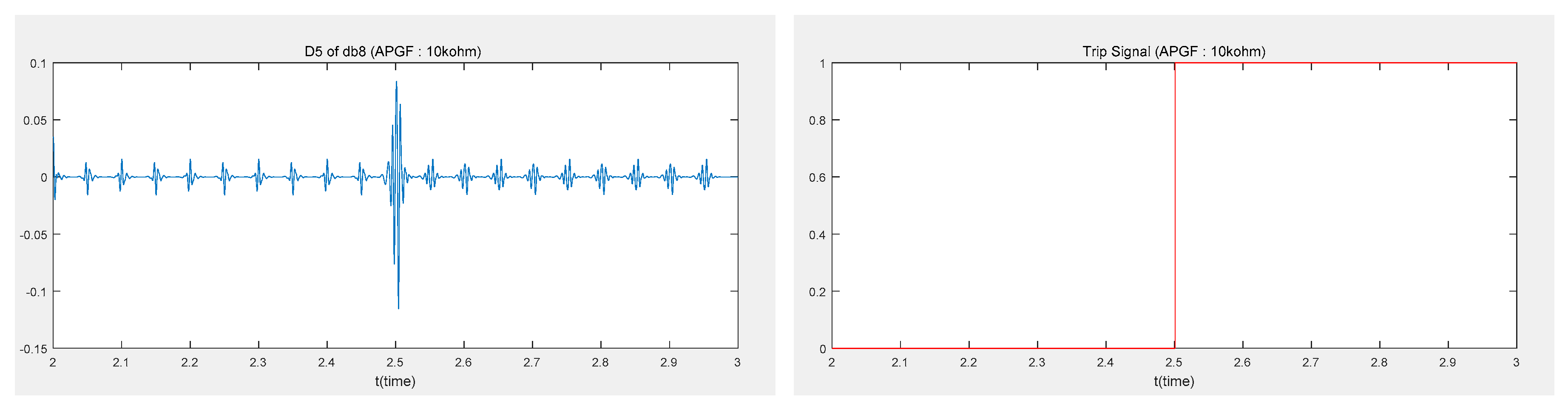
In addition, the proposed hybrid method for ground fault detection was implemented using a MATLAB script m-file. In the implemented method, the d5 value of db8 was used and the threshold value was set to 0.055 mA. Figure 8 shows the simulation result under pole to ground (PtoG). The left side indicates the analysis of , and the right side indicates the fault discrimination trip signal. That is, the left waveform represents the d5 waveform of db8, and the right waveform represents the trip signal. When the ground fault occurred, a signal value of 0.118 mA appeared, and it can be seen that a trip command to the circuit breaker had occurred by detecting the fault. The detection time of the proposed method was about 0.056 s in this case.
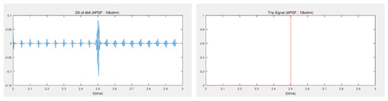
Figure 8.
The simulation result under pole to ground (PtoG).
Table 1 shows the performance analysis results of the proposed hybrid method. As shown in Table 1, the load variation and the fault resistance varied from 1 to 500 kΩ, representing the maximum value of magnitude in case of fault and of magnitude in steady state. From Table 1, we can see that the proposed fault detection method can detect up to 500 kΩ by setting the maximum threshold value of the fault resistance to determine the fault, the ground fault can be detected by setting the d5 signal value of db8 of the measured current to be 0.055 mA.

Table 1.
The performance analysis results.
The proposed hybrid method can be simulated by providing DWTs of order 1, 2, 4, and 8 at db8 in the PSCAD internal library. In the selected d5 of db8, the threshold value was set to 0.055 mA and used for ground fault detection. PSCAD simulations were performed for ground fault, short circuit fault, and load variation, and the results are that trip commands were confirmed in each case.
3.3.1. Ground Fault
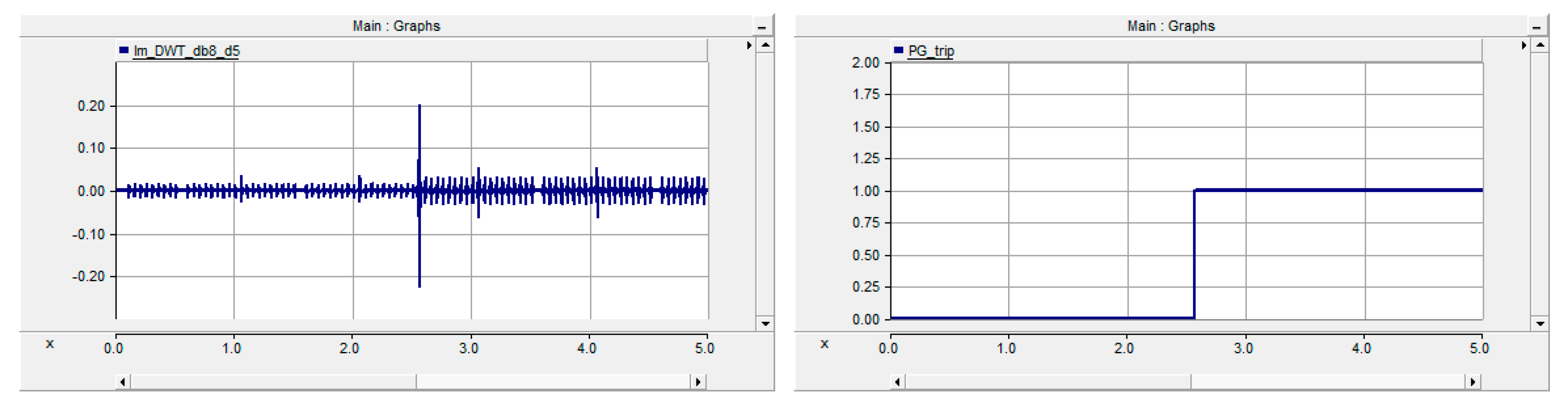
The pole to ground (PtoG) fault was simulated by generating a fault at 2.5 s when the fault resistance was 10 kΩ. Figure 9 shows the simulation result under PtoG. The left side indicates the analysis, and the right side indicates the fault discrimination trip signal. From Figure 9, it can be seen that the magnitude increases to 0.37 mA at 2.5 s where the fault occurred. Additionally, it can be seen that a trip signal occurred at 2.563 s at the fault inception point. That is, the fault detection time was 0.063 s.
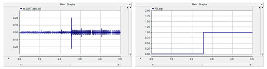
Figure 9.
The simulation result under pole to ground (PtoG).
3.3.2. Short Fault
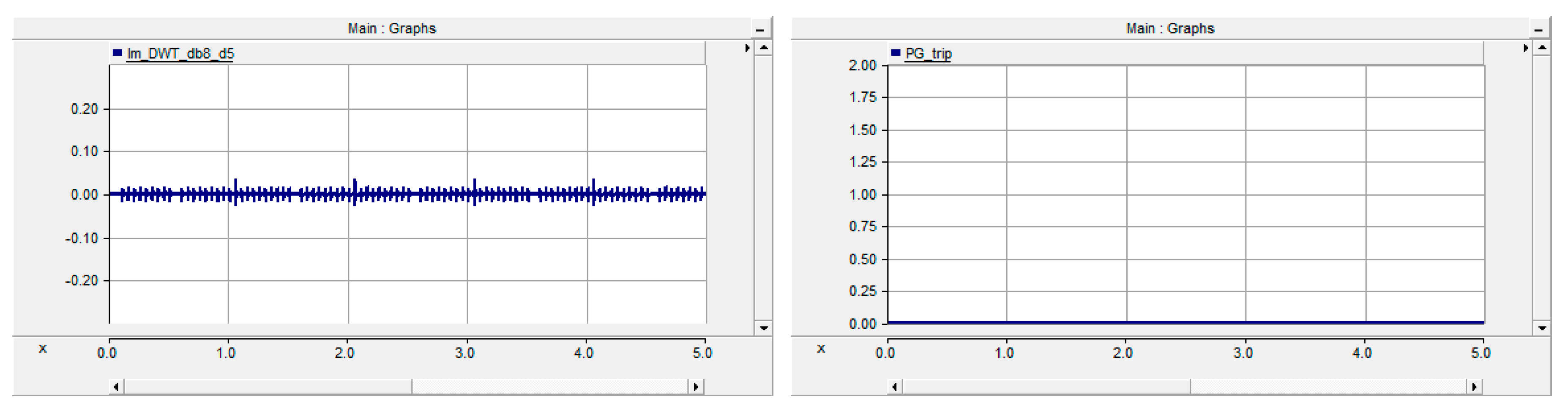
The pole to pole (PtoP) fault was simulated by generating a fault at 2.5 s when the fault resistance was 10 kΩ. Figure 10 shows the simulation result under PtoP. It can be seen that even when a PtoP fault occurred, the result did not change much. Additionally, it can be seen that a trip signal was not issued at the fault inception point. That is, the proposed hybrid method did not result in maloperation under PtoP.
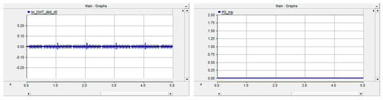
Figure 10.
The simulation result under pole to pole (PtoP).
3.3.3. Load Change
We performed the load simulation with a load of 420 kW and then reduced the load by 50% at 2.5 s. Figure 11 shows the simulation result under load change. It can be seen that even when the load changed, the result did not vary greatly. Additionally, even when the load fluctuated, the proposed detection method did not result in maloperation and the trip signal was not issued.

Figure 11.
The simulation result under load change.
4. Comparison of the Conventional and the Proposed Method
The conventional method detects a ground fault by calculating the leakage resistance [14,15,17]. However, the proposed hybrid method detects a ground fault by calculating the detail coefficient of the DWT of the measured current. Both methods were simulated using PSCAD. Table 2 shows the comparison of the fault detection time between the two methods while varying the fault resistance under PtoG. From Table 2, we can see that the conventional method tends to decrease the fault detection time as the fault resistance increases, and the proposed method tends to exhibit a constant fault detection time regardless of an increase in the fault resistance. In particular, the fault detection time of the proposed method was faster than that of the conventional method. The proposed method was able to detect with an average detection time of 0.052~0.056 s. From the comprehensive results of the simulations performed, the proposed hybrid detection method did not result in maloperation and the ground fault was detected accurately and rapidly.
Table 2.
The comparison of the fault detection time between the conventional and the proposed method.
5. Conclusions
Ground faults in ungrounded LVDC microgrids are difficult to detect because there is little fault current, little change in current, and no current path. In this paper, a hybrid method was proposed to accurately and rapidly detect ground faults in IT system LVDC microgrids. The method consists of the detailed coefficients of DWT using a signal injection method in an ungrounded LVDC microgrid.
First, the ungrounded LVDC microgrid was modeled using PSCAD, and the proposed method and various conditions were simulated. The optimal selection of order and detail of Daubechies was performed. D5 signal value of db8 for fault determination using the main method was selected. The appropriate threshold though the analysis was about 0.055 mA. Then, the method was tested through simulation of various conditions, such as ground fault, short fault, and load variation through PSCAD. Additionally, a comparative study with the conventional method was performed. The result of comparison of the fault detection time, the proposed method appeared faster than in the conventional method.
As a result of comprehensive tests, it was found that there was no malfunction during short-circuit fault nor load change. Correct detection operation was also represented during ground fault occurrence.
Author Contributions
investigation, K.-M.L.; supervision, C.-W.P.; visualization, K.-M.L.; writing—original draft, C.-W.P. All authors have read and agreed to the published version of the manuscript.
Funding
This research was funded by the korean institute of electrical engineers (KIEE).
Conflicts of Interest
The authors declare no conflict of interest.
References
- Cho, J.T. Development and implementation of DC distribution. In Proceedings of the 2018 KIIEE Annual Spring Conference, Gangwon, Korea, 16–18 May 2018; pp. 1–33. [Google Scholar]
- Lee, K.M.; Park, C.W. Performance Verification of the Interconnection Distribution System by PV and BESS. In Proceedings of the 2018 KIEE Electrical Machinery and Energy Conversion Systems Spring Conference, Gangwon, Korea, 19–21 April 2018; pp. 152–154. [Google Scholar]
- Wang, D.; Emhemed, A.; Burt, G.; Norman, P. Fault Analysis of an Active LVDC Distribution Network for Utility Applications. In Proceedings of the 2016 51st International Universities Power Engineering Conference (UPEC), Coimbra, Portugal, 6–9 September 2016. [Google Scholar]
- Carminati, M.; Ragaini, E.; Tironi, E. DC and AC ground fault analysis in LVDC microgrids with energy storage systems. In Proceedings of the 2015 IEEE 15th International Conference on Environment and Electrical Engineering (EEEIC), Rome, Italy, 10–13 June 2015; pp. 1047–1054. [Google Scholar]
- Lee, K.M. A Study on Modeling and Fault Analysis of Low Voltage Direct Current Grid. Master’s Thesis, Gangneung-Wonju National University, Gangwon, Korea, 2017; pp. 1–52. [Google Scholar]
- Lee, K.M.; Park, C.W.; Ahn, T.P. In Proceedings of the High-Speed Circuit Breakers for Low-Voltage DC Distribution System, KEPRI Research Proposal, Gangwon, Korea, 30 June 2016; pp. 1–160.
- Chang, S.Y. LVDC distribution technology trend. In Proceedings of the 2018 KIIEE Annual Spring conference, Gangwon, Korea, 16–18 May 2018; pp. 1–29. [Google Scholar]
- Kim, H.S.; Han, S.Y.; Han, H.S. Development of DC Leakage Current Sensor for Solar Power Generation System. Trans. KIEE 2014, 63, 828–833. [Google Scholar] [CrossRef]
- Hyoek, J.J.; Kim, C.J.; Song, J.I.; Noh, C.H.; Gwon, G.H.; Kim, C.H. Development of Ground Fault Detection Method in Unearthed Low Voltage DC Distribution System using Probe Unit. In Proceedings of the 2016 KIIEE Autumn Conference, Seoul, Korea, 11 November 2016; p. 69. [Google Scholar]
- Jung, J.Y.; Kwon, Y.J. An analysis of protection devices for IT grounding system applied on PCS. In Proceedings of the 2018 24th International Conference on Electrical Engineering, Seoul, Korea, 24–28 June 2018. [Google Scholar]
- Kim, H.J.; Cho, Y.P.; Kim, J.H.; Cho, J.T.; Kim, J.Y. Demonstration of the LVDC distribution system in an island. In Proceedings of the 2017 24th International Conference & Exhibition on Electricity Distribution (CIRED), Glasgow, UK, 12–15 June 2017; pp. 2215–2218. [Google Scholar]
- Karmacharya, I.M. Fault Location in Grid Connected Ungrounded PV Systems Using Wavelets. Master’s Thesis, University of Saskatchewan, Saskatoon, SK, Canada, 2016; pp. 1–138. [Google Scholar]
- Park, J.D. Ground Fault Detection and Location for Ungrounded DC Traction Power Systems. IEEE Trans. Veh. Technol. 2015, 64, 5667–5676. [Google Scholar] [CrossRef]
- Olszowiec, P. Insulation Measurement and Supervision in Live AC and DC Unearthed Systems, 2nd ed.; Springer: Heidelberg, Germany, 2014; pp. 1–180. [Google Scholar]
- Bender. ISOMETER IRDH375. Manual; Bender: Exton, PA, USA, 2017; pp. 1–96. Available online: https://www.bender.de/en/products/insulation-monitoring/isometer_irdh375 (accessed on 20 May 2020).
- ABB. Insulation Monitoring Relays CM-IWN.4/5/6; Data Sheet; ABB: Zurich, Switzerland; pp. 1–20. Available online: https://docs.rs-online.com/2d33/0900766b812cdbf0.pdf (accessed on 20 May 2020).
- Schaefer, O.; Schepp, K. Method and Device for Monitoring the Insulation of Ungrounded DC and AC Voltage Networks. U.S. Patent US9,069,025 B2, 30 June 2015. [Google Scholar]
- Chen, P.; Xu, B.; Li, J. A traveling wave based fault locating system for HVDC transmission lines. In Proceedings of the 2006 International Conference on Power System Technology, Chongqing, China, 22–26 October 2006; pp. 1–4. [Google Scholar]
- Schweitzer, E.O.; Guzmn, A.; Mynam, M.V.; Skendzic, V.; Kasztenny, B.; Marx, S. Locating faults by the traveling waves they launch. In Proceedings of the 2014 67th Annual conference for Protective Relay Engineers, College Station, TX, USA, 31 March–3 April 2014; pp. 95–110. [Google Scholar]
- Alam, M.K.; Khan, F.H.; Johnson, J.; Flicker, J. PV arc-fault detection using spread spectrum time domain reflectometry (SSTDR). In Proceedings of the 2014 IEEE Energy Conversion Congress and Exposition (ECCE), Pittsburgh, PA, USA, 14–18 September 2014; pp. 3294–3300. [Google Scholar]
- Stephane, M. A Wavelet Tour of Signal Processing, 3rd ed.; Academic Press: New York, NY, USA, 2008. [Google Scholar]
- Félix, C.S.; Walter, F.G.; Raúl, G.C.; Stephane, C.D. Multiresolution analysis based on Mallat pyramidal algorithm applied to GPR data. In Proceedings of the 15th International Conference on Ground Penetrating Radar, Brussels, Belgium, 30 June–4 July 2014; pp. 647–650. [Google Scholar]
- Yang, R. The Study of Locating Ground Faults in DC Microgrid Using Wavelet Transform. Master’s Thesis, University of Wisconsin, Milwaukee, WI, USA, 2016. [Google Scholar]
- Karmacharya, I.M.; Gokaraju, R. Fault Location in Ungrounded Photovoltaic System Using Wavelets and ANN. IEEE Trans. Power Deliv. 2018, 33, 549–559. [Google Scholar] [CrossRef]
- IEC International Standard. Electrical Safety in Low Voltage Distribution Systems up to 1000 V a.c. and 1500 V d.c.–Equipment for Testing, Measuring or Monitoring of Protective Measures-Part 8: Insulation Monitoring Devices for IT Systems, IEC 61557-8, 3nd ed.; IEC International Standard: Geneva, Switzerland, 2014; pp. 1–47. [Google Scholar]

© 2020 by the authors. Licensee MDPI, Basel, Switzerland. This article is an open access article distributed under the terms and conditions of the Creative Commons Attribution (CC BY) license (http://creativecommons.org/licenses/by/4.0/).