Abstract
Estimating the state of charge (SOC) of Li-ion batteries is an essential task of battery management systems for hybrid and electric vehicles. Encouraged by some preliminary results from the control systems field, the goal of this work is to design and implement in a friendly real-time MATLAB simulation environment two Li-ion battery SOC estimators, using as a case study a rechargeable battery of 5.4 Ah cobalt lithium-ion type. The choice of cobalt Li-ion battery model is motivated by its promising potential for future developments in the HEV/EVs applications. The model validation is performed using the software package ADVISOR 3.2, widely spread in the automotive industry. Rigorous performance analysis of both SOC estimators is done in terms of speed convergence, estimation accuracy and robustness, based on the MATLAB simulation results. The particularity of this research work is given by the results of its comprehensive and exciting comparative study that successfully achieves all the goals proposed by the research objectives. In this scientific research study, a practical MATLAB/Simscape battery model is adopted and validated based on the results obtained from three different driving cycles tests and is in accordance with the required specifications. In the new modelling version, it is a simple and accurate model, easy to implement in real-time and offers beneficial support for the design and MATLAB implementation of both SOC estimators. Also, the adaptive extended Kalman filter SOC estimation performance is excellent and comparable to those presented in the state-of-the-art SOC estimation methods analysis.
1. Introduction
Currently, hybrid and electric vehicles (EVs) represent a means of transport with low CO2 emissions. Also, soon, the energy required for these vehicles is expected to be provided by clean, renewable energy sources, such as solar panels. An essential feature of EVs is the recovery of energy they would lose during braking. Of various energy storage systems (ESS), “electrochemical batteries are devices that store chemical energy converted then into electricity to power the electric vehicles; they are preferred over capacitors and flywheels, due to their higher energy density” [1]. Based on a wide range of powers, three main categories are mentioned in [1], namely “EVs light electric vehicles with a power demand of less than several kilowatts, sedan vehicles, including electric sedan hybrid vehicles (HEVs) with a power up to 100 kW and heavy vehicles, used for public transport, with a power exceeding 100 kW”. For electric powertrains, the “lithium-ion (Li-ion) battery represents a good choice for EVs/HEVs” [1]. Today, it is already becoming a reality that, “among the batteries with low memory effects”, the Li-ion outperforms the most popular nickel-based technologies. They excel by “lighter weight, high density of energy, long life and low self-discharge rate” [1]. However, HEVs/EVs continue to be powered for a long time by both nickel-metal hydride (Ni-MH) batteries and lithium-ion [1,2,3,4,5,6,7,8,9,10,11,12]. The strengths and weaknesses in “terms of cost, specific energy and power, safety, life span performance for the main different chemistries” are analyzed in [1]. Hard research work is being carried out in the field of lithium-ion batteries to increase their energy density, and to take advantage of the advancement of anode and cathode material technologies. The “common materials used for the positive electrode are cobalt oxide, manganese oxide, iron phosphate, nickel manganese cobalt oxide and nickel cobalt aluminum oxide” [1]. Among them, lithium nickel-manganese-cobalt oxide battery is a suitable choice for EVs since it offers “an excellent trade-off between safety, capacity and performance” [1]. The most popular cobalt Li-ion (Li-ion Co) battery “used in consumer products was believed to be not robust enough”; nevertheless, due to its “high energy density”, this “computer battery” power nowadays “the Tesla Roadster and Smart Fortwo ED small cars”. The behaviour of the battery changes during deep cycles when “its capacity decreases rapidly” and, it is also sensitive to “high mechanical, thermal or electrical stresses” [6,10]. Specifically, the power of the battery “decreases drastically in cold weather”, and “when operating at high temperatures, its performance and life cycle visibly deteriorate” [10]. To avoid these situations and to extend the battery life, a “cooling and heating” system is usually installed. [6,10]. Additionally, the lithium-ion battery is “vulnerable to short-circuiting and overcharging” which could lead to a “combustion reaction, explosion and fire” as is mentioned in [6,10]. Thus, to “prevent overcharging of batteries in hazardous situations”, the battery management system (BMS) monitors the battery cells through a “precise voltage control system” [10]. Particular progress is being made today in “lithium-air” and in “nanotechnologies” batteries, as they “have a higher energy density due to oxygen being a lighter cathode and a freely available resource”, as mentioned in [13]. Of course, new technology also means high costs, but battery prices are gradually declining over time, as the manufacturing capacity of batteries becomes expanding as well. The Li-ion Co battery is an essential component of BMS which has as its primary function “improving battery performance, extending its life and operating safely” [3,10,11,12]. Therefore, it must continuously monitor, through the sensors, the internal parameters of the battery, such as the SOC, temperature, cells’ currents balance and voltage [3,10].
SOC as an internal battery state, is a priority task for BMS to monitor, as it severely affects battery health and battery life [2,3,5,6,7,10,11,12]. In references [2,3,6,7,8,9,10,11,12] is defined as an “available battery capacity”, which cannot be measured directly; therefore, an estimation technique is needed to prevent hazardous situations and to improve battery performance [3,10,11]. Mostly, the battery SOC estimation techniques are model-based, as is well documented in [7,8,9,10,11,12,13,14,15,16,17,18,19,20,21,22,23,24].
In conclusion, motivated by some preliminary results of our research, published in [10,11,12], this article focuses on the selection of the Li-ion Co battery model, the design and implementation of two real-time SOC estimators on a MATLAB simulation platform. The other chapters of this paper are structured as follows. In Section 2 are described the BMS, the selection criteria, the parameters of the battery and identifies the main disturbances that affect the functionality and the battery life. Also, is made a detailed analysis of state of the art on SOC measurement and estimation methods reported in the literature, and at the end of the same section are presented some modelling aspects and validation of Li-ion Co battery. In Section 3 are designed and implemented in MATLAB an adaptive extended Kalman filter (AEKF) and a linear observer (LOE) SOC estimators. The MATLAB simulations result, and rigorous performance analysis are presented at the end of the section. Section 4 is assigned for discussions, and Section 5 concludes the research paper contributions.
2. Lithium-Ion Battery-Cell Modelling and Validation
In this section, we focus our attention on the following topics regarding the Li-Ion batteries cells and packs:
- (1)
- BMS—definition, multitask safety functions, hardware and software components.
- (2)
- Battery selection criteria.
- (3)
- Battery parameters test.
- (4)
- Disturbances that affect battery functionality and the life span.
- (5)
- Measurement and estimation.
- (6)
- Cell modelling and validation test.
2.1. Battery Management System; Definition, Multitask and Safety Functions, Hardware and Software Components
A most comprehensive and mature Battery Management System (BMS) is an analogue-digital multitasking safety functions device integrated into the battery control system structure. The main task is to perform “a variety of safety functions to prevent the voltage, temperature and current in the battery cells from exceeding the specified limits”, as stated in [16]. The hardware components include those regarding “the safety circuitry, sensors, data acquisition, charging and discharging, control, communications and thermal management” [12]. In most automotive applications, the BMS performs tasks regarding “the safe operation and reliability of the battery, protecting battery cells and battery systems against damage, as well as battery efficiency and service life” [16]. Besides, it achieves interfacing, protection, control voltage, fault detection diagnosis and isolation (FDDI) and performance management functions, as is revealed in [16]. In a centralized configuration, it combines “into a single printed circuit board (PCB)” up to three module levels into hierarchical architecture, such as at the first level is located “the battery cell monitoring unit” (“data acquisition”), at the second one is the “module management unit” (“cell supervisor circuit” and at the highest level is the “package management unit” (“central management unit”) [16]. Thus, the required tasks can be managed and distributed among different subcomponents through PCB connected to the battery cells. Moreover, its advanced modular topology, known as “the master-slave-topology” is an exciting feature [16].
The advantage of this configuration consists of reducing to a minimum “the functions and the elements of the slaves” such that the “master” to implement only the functions related to the battery system [16]. One of the most critical parameters controlled by the BMS is the temperature inside the battery. As it was mentioned in the Introduction section, temperature significantly affects battery performance and, for most cases, when it exceeds the maximum limits, it leads to “fire and explosion”, known as “thermal runaway” process; it is an “irreversible process” with a significant heat “dissipated from the battery cells casing” [16]. In a battery pack, the battery’s cells can be connected in series, parallel or as mixt combinations to “adapt the voltage level and the battery capacity” to meet the requirements of an HEV/EV or stationary storage applications. Moreover, the primary constraint of the functionality of any BMS, regardless of its chemistry, is the maximum cell voltage measured on the cell monitoring unit. Of the Li-ion batteries, “lithium-iron-phosphate cells are one of the lowest voltage batteries with a maximum of 3.65 V, while for the widespread nickel-manganese-cobalt cells the maximum voltage is 4.2 V” [16]. At least one “communication interface” uses a “CAN-bus communication line for easy interfacing with other controllers in the car environment” [16]. Moreover, currently, the “wireless” devices “operating via wireless networks have promising potential to significantly reduce wiring, connectors and cable effort during assembly” [16].
However, it is possible to disturb the wireless network by “electromagnetic noise inside the car and outside entities, which can create safety and security issues” [16].
For each safety issue, it is necessary to prevent “the deep discharge and the overcharge” of the battery’s cell. Thus, the SOC of the battery pack is one of the most critical parameters estimated that keeps the “track” of the energy flow and reacts anytime when it is not operating within the specified range [16]. If SOC exceeds the limits, an alarm signal shall be sent as soon as possible to the “vehicle systems” concerned to prevent possible damage. Also, the battery cells need protection from possible damage generated during a “deep discharge”, such as dangerous “internal short circuits” [16].
Like, in the case of an overload, the information is sent to “propulsion controller” that decides to “stop charging the battery” anytime if the “maximum limit value is reached” [16]. Among the main software components of the BMS are highlighted the following [12]:
- Estimation and monitoring the battery SOC/SOH.
- The currents balancing algorithm.
- FDDI estimation techniques.
These components control the hardware operations, receive signals from sensors and “implement in real-time the estimation of SOC, SOH algorithms and of possible faults using FDDI techniques” [10]. Also, the BMS fulfil the task of estimation and monitoring the battery internal and insulation resistances [10,11].
Soft battery failures are detected using FDDI estimation techniques and identify defective components and “abnormal” functionality. In [10] are mentioned the sensor voltage faults (gain and drift) in measured terminal battery voltage, sensor current faults, sensor temperature faults, and fan motor faults. The estimation of sensor faults is particularly useful for improving the “reliability” of BMS [10]. Well, “several faults” have their roots in defective components, “safety component failures or human errors” [10]. Usually, the fault can be persistent, intermittent, unique or overlap with other faults, for which its root cause may be a faulty cable connection, a sensor bias (voltage, current) or a temperature drift [10]. A faulty fan is detected only when a complete dc motor failure occurs.
2.2. Battery Selection Criteria
The main battery selection criteria in all HEV/EVs applications can be found in [10], including “energy and power density, capacity, weight, size, lifespan, cost and memory effect” features that make the difference for selecting any battery. Of these, power and capacity are necessary to optimize the design of the battery, selecting the most suitable cells and package size, able to be adapted to a custom application [10]. Furthermore, given that most HEVs/EVs operate for different climatic conditions of harsh operation and stress caused by abuse and vibration, the size of the battery needs to be adequate to provide a certain amount of energy [10]. Additionally, some constraints can be imposed on the capacity of the battery in terms of “depth of discharge (DOD), SOC, discharging rate and generative braking charge”, as is stated in [10].
2.3. Battery Parameters Test
Mainly, the Li-ion battery life span depends significantly on SOC real-time estimation, aging effects, temperature operating conditions and frequency “of the changes in operating cycles” [10].
Also, internal DC resistance and insulation resistance are among the most critical parameters of the battery that have a significant impact on battery life. Related to first battery parameter, in reference [10] the life cycle is defined as “the number of the cycles performed by the battery before its internal resistance increases 1.3 times or double than its initial value when was new”. The main factors that affect the internal resistance are revealed in reference [11], including “the conductor and electrolyte resistances, ionic mobility, temperature effects and changes in SOC”.
Related to the second battery parameter, in reference [10] is stated that the “high voltages components, electrical motor, battery charger and its auxiliary device deal with a large current and insulation”; thus, the “insulation issues” are under investigation during the” battery design stage” [10]. The harsh “working conditions” detailed in [11], have a significant impact on “fast aging of the power cable and insulation materials”, decreasing drastically “the insulation strength” and “endanger the personnel”. Thus, it needs to ensure safe operating conditions for personnel are required to evaluate the insulation conditions for entire HEV’s BMS. Many details about the insulation standards can you can find in [11]. In conclusion, to ensure the insulation security of on-board BMS, it is necessary to “detect the insulation resistance and raise the alarm in time” as is mentioned in [10].
2.4. Disturbances that Affect the Battery Operation and the Life Span
In “real life”, the primary disturbances affecting battery operation and life are well-identified in [10], and include:
Chemical changes—leading to damage to the battery cells.
Active chemicals depletion—take place under different operating conditions, as was mentioned in the Introduction section.
Temperature—battery operation significantly depends on the temperature, which also affects the performance of the battery.
Pressure—is affected by the temperature that increases the internal pressure inside the battery cell.
DOD—is related to SOC and depends on operating temperature conditions and discharge rate, becoming “proportional to the amount of active chemicals” [10].
Charging level limits—the full charge of the battery must be prevented to keep the battery safe.
Charging rate—to keep the battery safe, discharging the battery at high rates should be avoided.
Voltage—to counteract “undesirable chemical reactions” inside the battery cells the values of the battery terminal voltage must be within a specified range [10].
Cell aging—cell aging is mainly affected by the current flow through the battery cells, as well as by the heating and cooling processes of the cells.
Coulombic efficiency (CE)—is an important performance indicator of the charging efficiency of the battery through which the electrons are transferred inside the battery. The CE rating of Li-ion batteries exceeds 99% and is among the highest values of any rechargeable battery.
Electrolyte loss—it has a significant impact on the capacity of the cells whenever there is a reduction in the active chemicals inside the battery.
Internal and insulation resistances—their impact was described in the previous subsection.
2.5. Li-Ion Battery SOC—State of the Art of Measurement and Estimation Methods Reported in the Literature
Basically, “the battery model, estimation algorithm selection, and cells balancing” have a high impact on SOC accuracy and robustness, as is stated in [17]. Also, in [17] the authors investigate several existing SOC estimation techniques reported in the literature field and analyze their “issues and challenges”. In reference [17] are well summarized the main Li-ion battery SOC estimation techniques related to HEVs/EVs field, including:
- (1)
- Conventional direct measurement methods.
- (2)
- Adaptive filter algorithms.
- (3)
- Learning algorithms.
- (4)
- Non-linear observers.
- (5)
- Hybrid methods.
Our investigations are motivated by the lack of a sensor capable of measuring the battery SOC and therefore it is necessary to estimate it. Several measurement methods and estimation techniques are well documented and summarized in [12,16,17,18].
2.5.1. Conventional Direct Measurement Methods
- (1)
- Laboratory tests and chemistry dependent methods. In the literature are reported the main four cell modelling methods that are briefly presented in [10]. Among these we highlight the following:
- A laboratory method for determining SOC—even if it is not suitable for the field of HEV applications, it is still one of “the most accurate SOC measurement” methods [10]. This method consists of completely discharging the battery, recording the “discharged ampere-hours” and then determining the “remaining cell capacity available”.
- Chemistry-dependent methods for other chemistries—unsuitable for Li-ion batteries.
- Open-circuit voltage (OCV) method. This method uses “the stable electromotive force (EMF) of the open circuit” and the SOC relationship to “estimate the SOC value”, as is stated in [17]. In [10] are presented in detail some reasons why this method is inadequate for the dynamic estimation of the Li-ion battery SOC. Moreover, since its OCV = f (SOC) characteristic is almost flat for a considerably broad range of SOC values, it isn’t easy in this approach to estimate SOC more accurately [18].
- Terminal voltage measurement method. The terminal voltage of the Li-ion battery is “based on the voltage drops on the internal impedances when the battery is discharging. Thus the EMF of the battery is proportional to the terminal voltage” [18]. Moreover, since the “EMF of the battery is approximately linearly proportional to the battery SOC, the terminal voltage is also approximately linearly proportional to SOC” [18]. The “disadvantage of this approach is a large estimated error in the terminal voltage of the battery at the end of battery discharge; it is due to a sharp drop of the terminal voltage” [18].
- (2)
- Electro-chemical method. In this approach, it is “estimated the average amount of Li concentration in the positive or negative electrodes” using “partial differential equations“ [17]. These models may achieve an “accurate terminal voltage prediction”, but “it would be difficult to measure all the required physical parameters on a cell-by-cell basis in a high-volume consumer product” [8].
- (3)
- Impedance direct measurement method. In this approach, the “measurements provide knowledge of several parameters, the magnitudes of which may depend on the SOC of the battery” [18]. Since the “battery impedance parameters and their variations with SOC are not unique for all battery systems” it is required many impedance experiments to identify its parameters [18].
- (4)
- SOC Estimation spectroscopy method. This method uses the battery impedance and internal resistance “to describe the intrinsic electric characteristic under any current excitation, if temperature, SOC and SOH are fixed”, but “it is not suitable for use in HEVs/EVs” applications [17]. The reason you can find in the same reference [17]. According to [17], “it is tough to measure online electrical impedance spectroscopy over a wide range of AC frequencies at the different charge and discharge currents, especially when the SOC and impedance relationship is not stable, and the cost is expensive”. Also, is mentioned in the previous subsection that the internal resistance of the Li-ion battery is measured in direct current (DC) and requires the “value of the voltage and current at a small-time interval” [17]. Then, the battery SOC “may be indirectly inferred by measuring present battery cell impedance” [10] and the battery internal resistance correlated “with known impedances at various SOC levels” [8,18].
- (5)
- Ampere-hour counting method. Based on this method is calculated “the amount of charge that flows in and out of the battery” [10]. In this approach, the SOC is estimated directly in an open loop, so the SOC estimate is not accurate due to the current measurement errors. Instead, in a closed loop, the same method can estimate the SOC more accurate [8,10]. The SOC estimate accuracy degrades the accuracy significantly when the battery is not “fully discharged after a complete charging cycle”. Since in the most cases, the battery doesn’t perform a full charge followed by a full discharge, “a significant drift is difficult to avoid”, and thus, since “the signal drifts, the efficiency of coulomb counting decreases” [10]. Also, the Ampere-hour (Ah) counting method becomes “less effective when the battery self-discharges is subject to temperature changes” [10]. The “unknown initial value of battery SOC, capacity fading, self-discharge rate, and current sensor errors are the main sources of errors for Ah counting method” [17]. The presence of “an accurate measurement sensor and a predefined calibration point can overcome the method’s drawbacks” [17]. Additionally, the estimation error “can be maintained at a low value by defining a correction factor and a re-calibration point” [10]. It is worth mentioning that this method is more accurate compared to other SOC calculation methods [10,17]. The most significant advantage of the Ampere-hour counting method is its low power computation cost, and it is secure and reliable when the sensor current measurements are accurate, and a re-calibration point is accessible [10,17].
- (6)
- Model-based method. Since the “previous mentioned methods are not appropriate for online SOC estimation and to achieve an accurate online SOC estimate value, suitable battery models need to be developed” [17]. Among the most suitable models for online SOC estimation are the electrochemical and equivalent circuit models (ECMs) [10,11,17]. More details about ECMs models you can find in [3,4,7,8,9,10,11,12,17]. In closing, “an ideal ECM should be able to simulate the actual battery terminal voltage to any charging or discharging battery input current”, as is stated in [17].
2.5.2. Adaptive Filter Estimators
The adaptive filter estimators improve the “accuracy and the robustness of the battery SOC estimation significantly and reduce” drastically the impact of measurement and process noises on the battery model [17], such those developed in [7,8,9,10,11,12,14,18]. Among the Kalman filtering estimation techniques in the field literature the Kalman filter [KF], extended Kalman filter (EKF) [4,7,8,9,11,17,18], adaptive Kalman filter (AEKF) [17], fading Kalman filter (FKF) [17], unscented Kalman filter (UKF) [12,14,18], sigma-point Kalman filter (SPKF) [17] and particle filter (PF) are reported [17].
The KF was developed by Rudolph Kalman in 1960 and currently has become the most popular estimation algorithm. It is an “optimum state estimator and intelligent tool” for linear systems [17]. Its EKF version is also a KF applied to the linearized dynamics of a non-linear system by using the first-order Taylor’s series expansion around the current value of the state estimate in each step of the algorithm, as developed in the next section and in [7,8,9,17]. A combination of KF state estimator and Ah Coulomb counting method can be used to “compensate for the non-ideal factors that can prolong the operation of the battery” [17]. The KF SOC estimator is the most used since it can estimate the battery SOC more accurately even if when the battery is affected by external disturbances mentioned in previous subsections.
Although, if the dynamics of Li-ion battery model are “highly nonlinear”, “linearization error may occur due to the lack of accuracy in the first-order Taylor series expansion under a highly non-linear conditions” [17]. The simplicity of the SOC EKF estimator design and implementation motivates researchers to apply this estimation technique for different Li-ion battery models, as in [4,7,8,9,11,16,17,18,19,20,21,22,23,24]. In [16] an exciting research project that performs a detailed and rigorous analysis of state of the art on Li-ion BMSs, including also a detailed presentation of the main SOC estimation techniques, among them the adaptive Kalman filtering techniques, is presented. Similarly, [17] presents an intense study of state of the art on Li-ion battery SOC estimation for electric vehicles that completely reviews of all the existing SOC direct measurement and estimation techniques reported in the field literature. Similarly, in [18] a brief review describing the SOC estimating methods for the same Li-based batteries is provided. In [19], the authors proposed a dual EKF for state and parameter estimation for a first-order EMC RC Li-ion battery model. The SOC simulation results reveal an excellent accuracy of the SOC estimate, but the robustness algorithm robustness is not investigated. Comparing the SOC simulation results obtained in current research work and in [19], one can observe an excellent accuracy, and the robustness of the algorithm developed in our research for several scenarios. In [20], the authors use an improved non-linear second-order RC EMC battery model and based on this model have developed an EKF algorithm to estimate the Li-ion battery SOC. The simulations are conducted on the MATLAB platform using two different driving cycles current profiles, namely Urban Dynamometer Driving Schedule (UDDS) and HWFET. The results are compared to those obtained by a Coulomb counting method and reveal an excellent SOC accuracy, but degradation is visible in the robustness performance to changes of battery model parameters values provided by two datasets, compared to the SOC estimator robustness performance designed in our research, for many scenarios introduced in Section 3. In [21] is developed a new application “model-based fault diagnosis scheme to detect and isolate the faults (FDDI) of the current and voltage sensors applied in the series battery pack based on an adaptive extended Kalman filter (AEKF)”. The AEKF algorithm is designed to estimate the magnitude of the faults. The FDDI scheme is validated in the MATLAB/Simulink platform, and the result of the simulations demonstrates the “effectiveness” of the proposed FDDI for “various fault scenarios using the “real-world driving cycles”.
The AEKF is an EKF with an adaptive feature, i.e., in the new design the EKF algorithm updates at each step the process and measurement noise covariance matrices to increase the accuracy of EKF SOC estimation. The same feature is also added to the EKF algorithm developed in our research that is very useful to increase the accuracy and the robustness of the SOC EKF estimator. In fact, by updating the noise covariance matrices, a new retuning procedure of the EKF parameters is not more required unlike the time consuming “trial and error” strategy. In the reference [21] you can see the effectiveness of the AEKF algorithm that estimates accurately four injected faults, the first is a fault assigned to a sensor current, and the other three faults are assigned to three different voltage sensors. The robustness of the FDDI technique is demonstrated for a 20% change in the SOC initial value and a current profile corresponding to a UDDS driving cycle. Unfortunately, the MATLAB simulations results don’t show the SOC estimated values, very useful to analyze the impact of each fault on the SOC estimation performance. In the reference [22] “an experimental approach is proposed for directly determining battery parameters as a function of physical quantities”. The battery model’s parameters are dependent on SOC and of the discharge C-rate. This approach is exciting since the battery model’s parameters “can be expressed by regression equations in the model” to derive “a continuous-discrete dual EKF SOC state and parameters estimates” [22]. A “standard correction step” of the EKF algorithm is applied to “increase the accuracy of the estimated battery’s parameters” [22]. The EKF simulation results with the experimental results for several operating scenarios reveal a high accuracy and the robustness of the estimator for correct identification of the battery parameters. In the reference [23] an adaptive fading EKF (AFEKF) is proposed for Li-ion battery SOC estimation accuracy and convergence speed. The AFEKF SOC estimator combines both structures AEKF and a fading EKF (FEKF). A FEKF “adopts a variable forgetting factor least square (VVFFLS)” to identify the Li-ion battery parameters [23]. The AFEKF estimator can reduce the SOC estimation error of less than 2%. Also, in our research, we add the same feature to the proposed AEKF SOC estimator, and the MATLAB simulation results reveal a high SOC estimation accuracy and robustness for many scenarios including three driving cycles tests UDDS, FTP and EPA-UDDS. Comparing the MATLAB simulation results obtained in [23] to those obtained in our research work, for same UDDS cycle, you can notify that the SOC estimator designed in [23] performs better in terms of accuracy. Instead, the proposed estimator in the current research performs better in terms of robustness and convergence speed. The speed convergence and robustness performance are revealed for a 20% decrease in SOC initial value in [23] and 30% in our case study.
In [24] an exciting online EKF SOC Li-ion internal resistance parameter estimator to “overcome defects from simplistic battery models” is developed. The battery is a first-order ECM RC model for which the internal resistance is dependent on SOC, temperature and aging effects.
For an accurate real-time internal resistance, the EKF estimated values “can be distinguished well” and also “improve the accuracy of SOC and SOH estimation” [24]. The internal resistance test device consists of a dc power supply source, a dc voltmeter, a pulse control switch and a microcontroller unit that controls the testing procedure, the dc power source, the switching time and voltage measurement. The EKF estimator is conceived as parameter estimator. Hence, its model is like for EKF state estimator. Still, in this case, the internal resistance dynamic is given by a slow varying first-order differential equation that has injected a Gaussian process noise. The EKF estimator can also estimate at the same time the SOC of Li-ion battery; thus, it is designed as a dual state-parameter EKF algorithm. The simulation results indicate an excellent accuracy of SOC estimate, for “a repeated current constant-constant voltage of 3200 mA discharge current and 1600 mA charging current, and the estimation error is smaller than 3%” [24]. Unfortunately, a new estimation result from a performance comparison is not possible since the input current profiles used in current research work (UDDS, FTP and EPA-UDDS) are entirely different than the current profile used in [24].
A viable alternative to EKF SOC estimator can be the unscented Kalman filter (UKF) and sigma point Kalman filter (SPKF) that avoid the linearization of nonlinear dynamics of the battery model; thus, they are more accurate and robust than EKF [10,11,14,17]. Also, a particle filter (FP) method is used to estimate the states, estimating the “probability density function” of a nonlinear dynamics of the Li-ion battery model, using a Monte-Carlo simulation technique, such as developed in [12,17].
2.5.3. Learning Methods
In this category the artificial neural networks (ANN), support vector machine (SVM), extreme machine learning (ELM), genetic algorithm (GA) and fuzzy logic (FL), well documented in [17], can be highlighted.
2.5.4. Linear and Nonlinear Observers
The nonlinear observers (NLO), sliding mode observer (SMO) and proportional-integral observer (PIO) are proposed to estimate the SOC of Li-ion batteries, and a detailed description can be found in [17].
2.5.5. Hybrid Methods
The hybrid method is a combination of two or more algorithms’ structures, such as an EKF-Ah algorithm, an adaptive EKF (AEKF) and a support vector machine (SVM), like the one developed in [17].
2.6. Li-Ion Battery Cell—Model Selection, Validation and Case Study
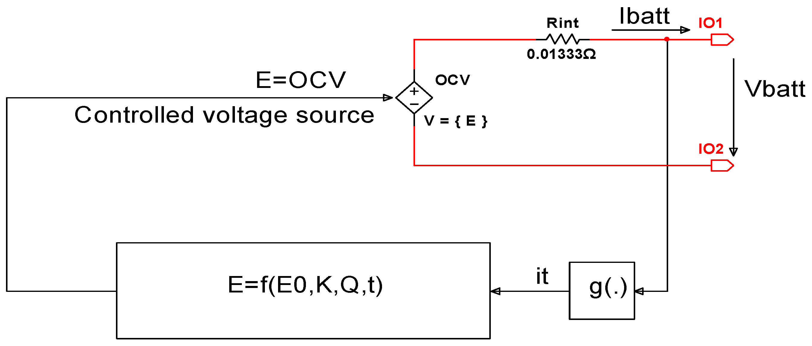
In this section, we are focused on the generic Li-ion Co cell model description in a bidimensional continuous and discrete-time state-space representation. Since “the new technologies heavily depend on battery packs, it is therefore important to develop accurate battery cell models that can conveniently be used with simulators of power systems and on-board power electronic systems”, such is mentioned in [25]. The Li-ion Co battery model adopted in this research paper is a generic MATLAB/Simscape nonlinear model suggested in [25] and depicted in Figure 1.
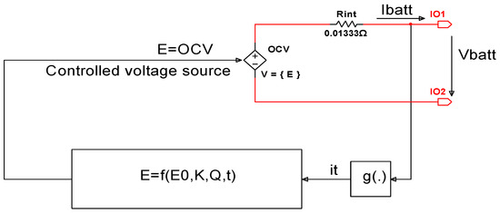
Figure 1.
The non-linear Li-ion Co battery generic model (see [25]). (it is common picture met in the literature, it is not copyright issues!).
In this schematic the battery is modeled by a controlled voltage source E, which is a no-load voltage (open circuit voltage (OCV)) [25], given by:
On the internal resistance is dissipated the power losses Ploss, useful to design the thermal model in the next section to simulate the temperature effects on the battery, given by:
The battery terminal voltage Vbatt is related to OCV according to following highly non-linear dynamic relationship:
where the meaning of all the variables and coefficients can be found in Table 1. Additionally, we attach the Coulomb counting equation to define the SOC of the battery, which is an important battery internal state supervised by BMS. It delivers a valuable “feedback about the state of health of the battery (SOH) and its safe operation”, as is mentioned in [10]. The battery SOC is defined in [10] as:

Table 1.
Description of Li-ion cobalt voltage model variables.
The battery SOC is 100% for a battery fully charged and, 0% for a battery fully empty. Typically, the battery SOC can be defined for a positive current discharging cycle as:
where is the Coulombic efficiency of the discharging cycle, while represents the maximum capacity of the battery capacity, typically , close to those provided in the battery manufacturer’s specs. The relation (5) can be written as a first order differential equation that, together with Equations (1) and (3), will be particularly useful for SOC state estimation in the next section of this research paper, i.e.:
It is worth mentioning that for a discharging cycle, the battery current in (6) is positive and for a charging cycle it is negative.
2.6.1. Li-Ion Cobalt MATLAB Simscape Model
A full representation of the generic battery model, dependent on the temperature and aging effects, is developed in MathWorks (Natick, MA, USA; www.mathworks.com) in the MATLAB R2019b/Simulink/Simscape/Power Systems/Extra Sources Library-Documentation. The MATLAB Simscape Li-ion cobalt battery cell specifications are shown in Table 2.

Table 2.
Li-ion Cobalt cell specifications.
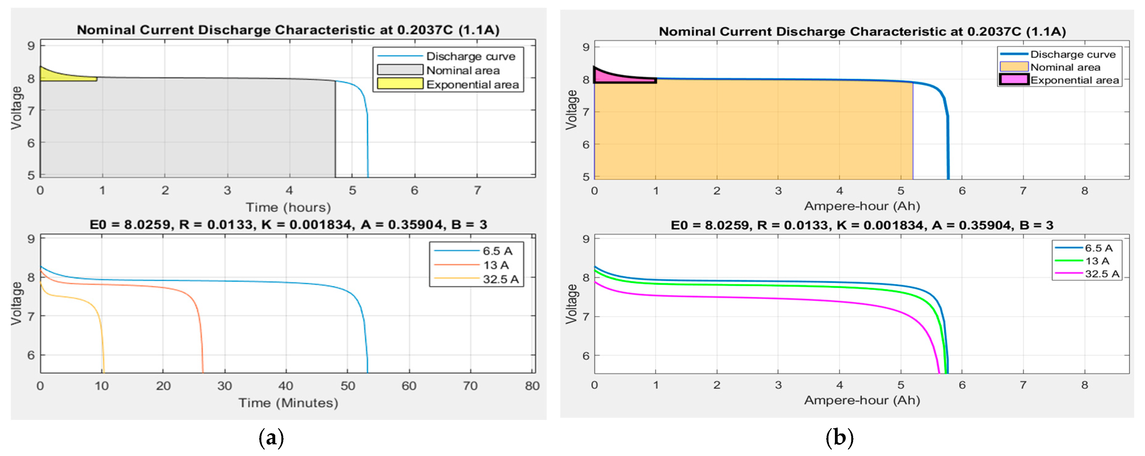
The MATLAB Simscape model of a generic battery is beneficial to set up a particular choice of battery chemistry and operation conditions that take into consideration the thermal model of the battery (internal and environmental temperatures) and also its aging effects. The battery terminal voltage, current and SOC can be visualized to monitor and control the battery SOH condition. The nominal current discharge characteristic according to a choice of the Li-ion Co battery having a nominal capacity of 5.4 Ah and a nominal voltage of 7.4 V is shown in Figure 2.
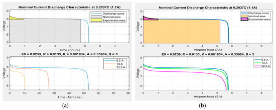
Figure 2.
Nominal discharge characteristic of Li-ion Co at 0.2037C-rate (1.1 A)-MATLAB generic model. (a) In hours (minutes) (b) In Ampere-hours (Ah).
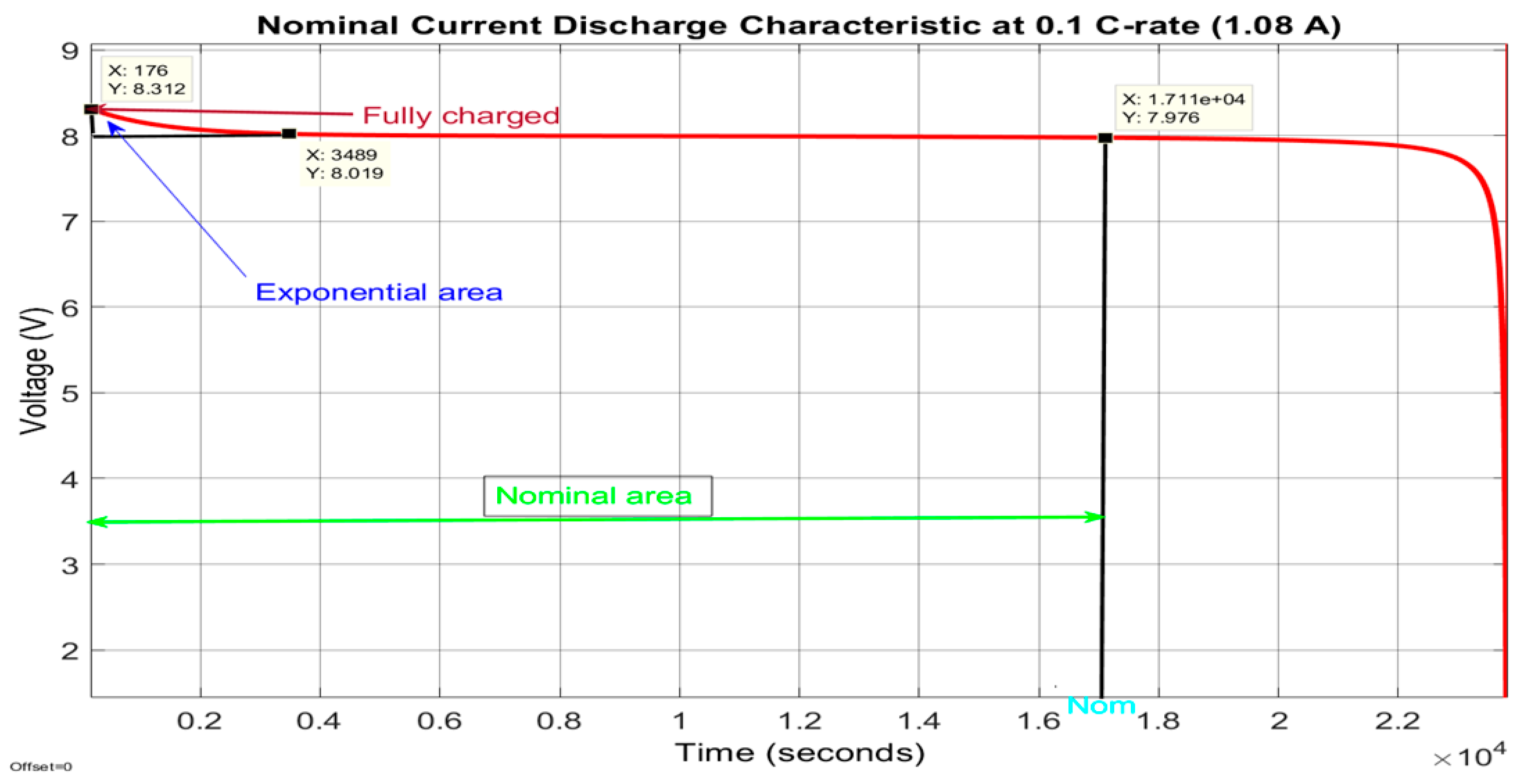
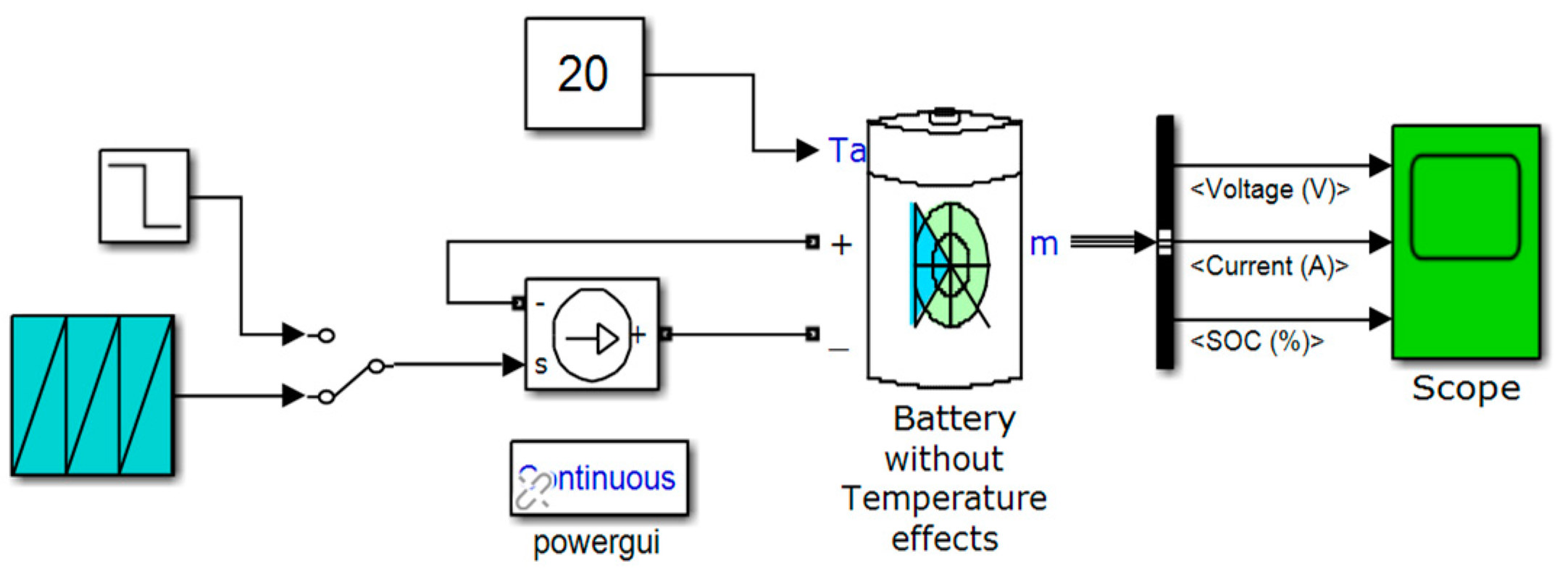
This characteristic corresponds to a constant discharge current of 0, 2037C-rate (0.2037 × 5.4 Ah = 1.1 A). The first battery characteristic from the top side of Figure 2 provides useful information about the estimated coefficients of the open-circuit voltage (OCV) included in Table 1, i.e., E0 = 8.0259 V, Rint = 0.01333 Ω, K = 0.001834 V, Aexp = 0.35904 V, and Bexp = 3 (Ah)-1. To show the evolution of the battery terminal voltage for different input current profiles, at the bottom of same Figure 2 other three nominal current discharge characteristics for three constant discharging currents (6.5, 13 and 32.5 A) are shown. These characteristics reveal that for the highest constant discharging current of 32.5 A, the discharging time of the battery decreases drastically to 10 min compared to 54 min corresponding to the smallest discharging current of 6.5 A. The same trend can be seen in Figure 3, where for a nominal discharging constant current of 1.08 A the Li-ion Co battery needs almost six hours to be fully discharged. The Simscape model of a generic battery set up for a Li-ion Co battery is shown in Figure 4.
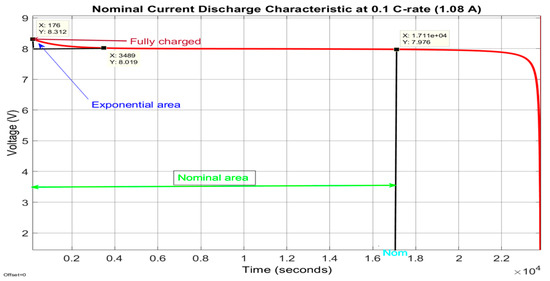
Figure 3.
Nominal characteristic for a constant current discharge of 1.08 A—details.
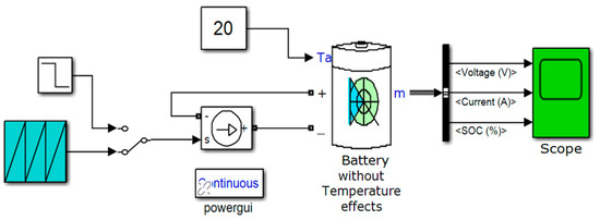
Figure 4.
The Simscape model of the generic 5.4 Ah and 7.4 V Li-ion Co battery (without temperature and aging effects).
2.6.2. Li-Ion Cobalt Model in Continuous Time State Space Representation
The purpose of this section is to select and design the most suitable Li-ion Co battery model, which excels in simplicity, accuracy and is easy to implement in the MATLAB real-time simulation environment. Specifically, an accurate battery model is useful to develop in the following section the proposed real-time SOC estimators, which must also be of high precision and robustness. Related to SOC is the DOD, defined in [10] as:
The SOH is another internal battery derived parameter defined in [10] “as the ratio of the maximum charge capacity of an aged battery to the maximum charge capacity when this battery was new”, as is also mentioned in [2,26]. The “actual operating life of the battery is affected by the charging and discharging rates, DOD, and by the temperature effects” [10]. Also, in [10] is stated that “the higher the DOD is, the shorter is the life cycle”, and to attain “a higher life cycle, a larger battery is required to be used for a lower DOD during normal operating conditions”, as is stated in [2,11,12]. Another important parameter for BMS in HEVs/EVs is the state of energy (SOE). From “engineering perspective, the SOE is more useful since it takes battery terminal voltage into account, which can predict the available energy for HEVs/EVs” [26].
While SOC indicates “the remaining capacity of the battery, the SOE indicates the remaining energy stored in the battery”, as is defined in [26]:
or equivalent to:
where , , represent the available battery energy, the load current and the “battery energy efficiency” respectively [26]. The input-output battery model Equation (1) is a simplified version of the original Shepherd’s combined model that follows the development from [25] and [27,28,29] replacing:
by:
where A and B are two empirical parameters that are determined by a curve fitting procedure. The advantage of new version is to get a simplified OCV nonlinear model dependent only on SOC, as is developed in [26].
In the case study, we follow the development from [25] corrected by making small changes to increase the model accuracy, as is suggested in [26]. The development from [25] has the advantage to determine the battery model parameters by extracting the values based on simple algebraic manipulations, directly from the battery type OCV curve specifications provided by manufactures [7,10,11,12,25]. According to (11), the input-output battery generic model Equation (3) in continuous time becomes:
Let’s now assign two state variables to the description (12):
Therefore, a new modelling version is developed for designing and implementing the Li-ion Co battery model. In the new version, the model is described in continuous time in a two-dimensional representation of the state space as:
and it is implemented in Simulink in the next subsection. The advantage of this representation is the model simplicity, its accuracy and easy to implement in real time.
2.6.3. Li-Ion Model in Discrete Time State Space Representation
To design both SOC estimators based on the adopted generic Li-ion Co battery model, the state space Equation (13) will be converted in discrete time representation. For SOC estimation purpose, a full Li-ion Co model in discrete time space representation is given in (15) and (16):
where , is a positive integer number, = is the sampling time, set to 1 s in all MATLAB simulations.
2.6.4. Model Validation on ADVISOR MATLAB Integrated Platform
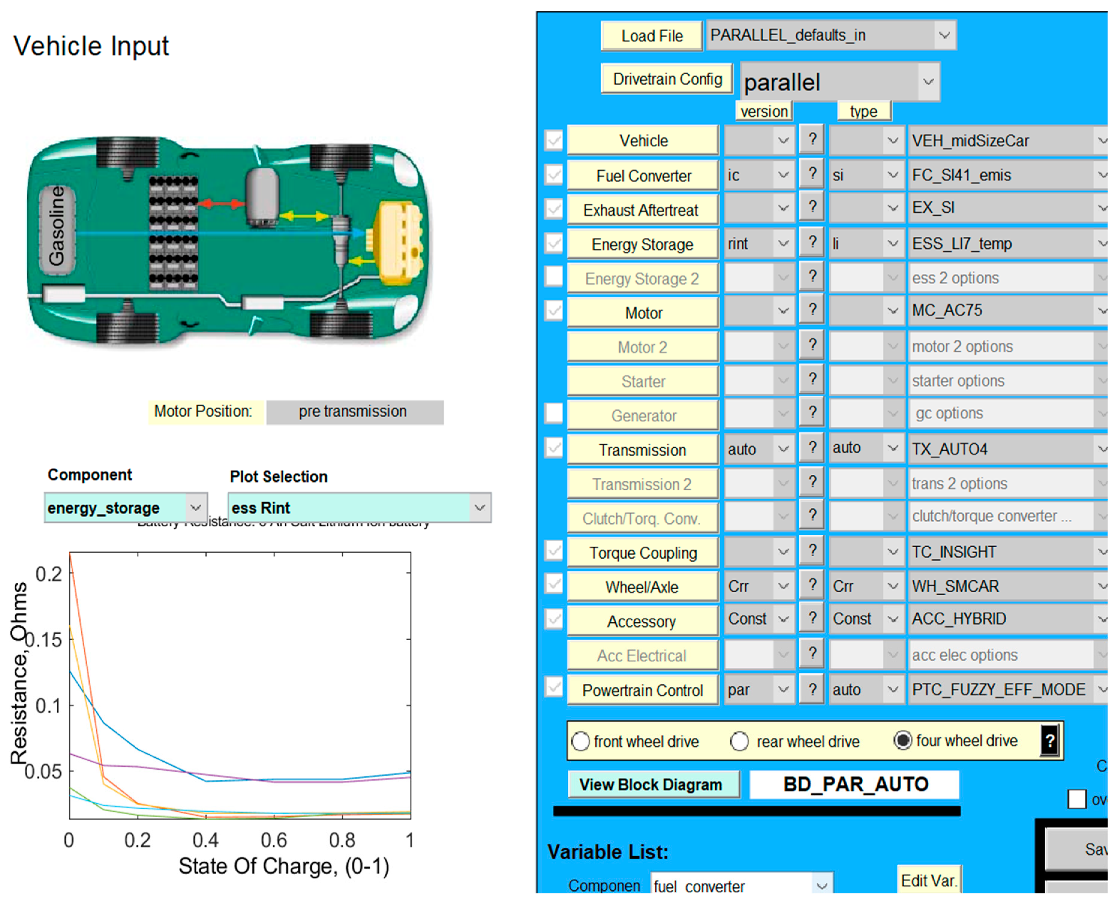
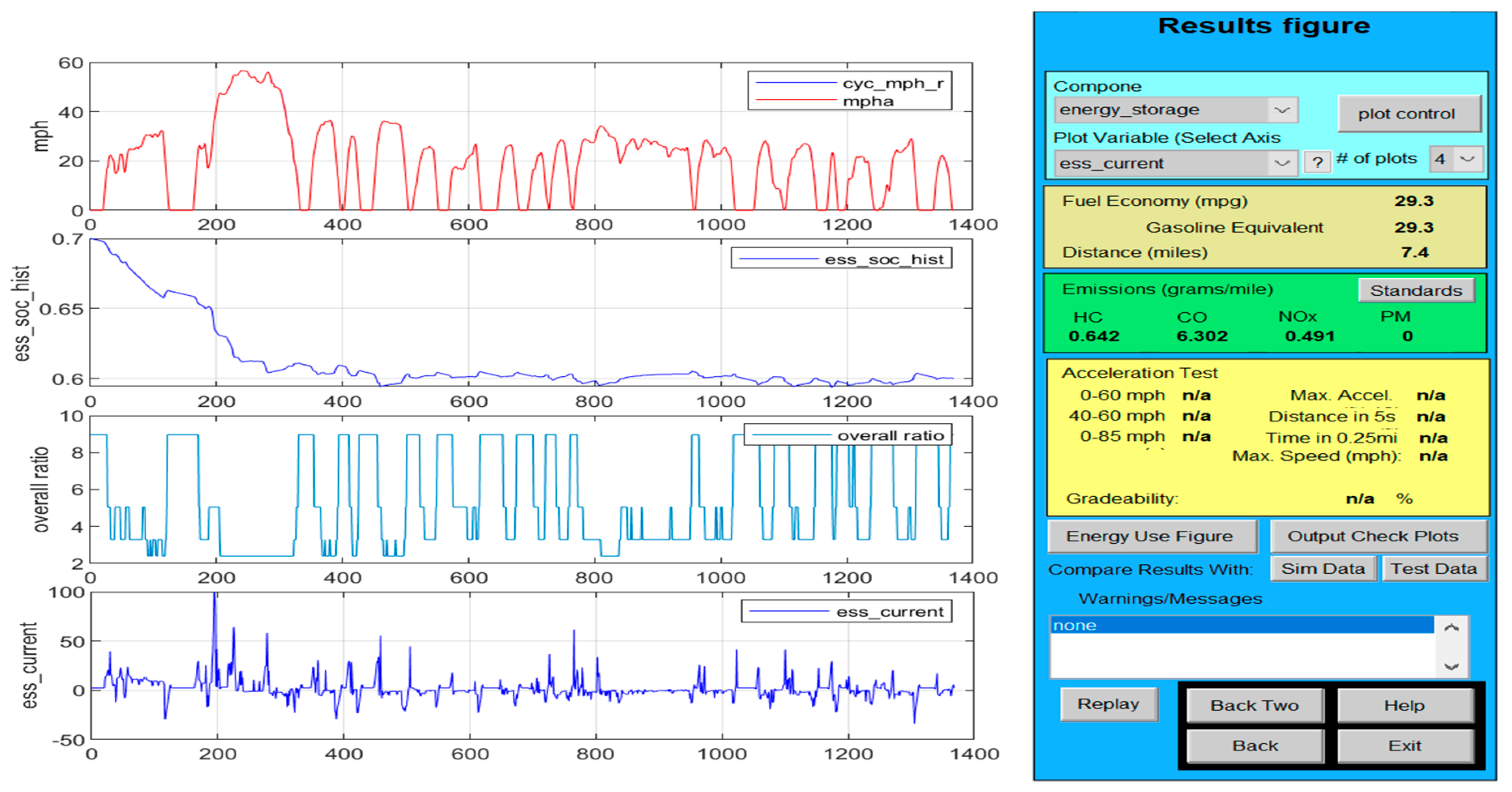
The validation of the Li-ion Co battery model is tested by using one or more driving cycles under different realistic driving conditions required for battery simulation tests. A collection of such of driving cycles profiles is stored in a large database of the US National Renewable Energy Laboratory (NREL) Advanced Simulator (ADVISOR) integrated into a MATLAB simulation environment [10]. The ADVISOR simulator is recommended by the excellent results obtained in [10] and by the fact that so far it has been one of the most used software design tools in the HEV/EV automotive industry, as mentioned in [11,29,30,31,32]. More details about this integrated ADVISOR MATLAB platform can be found in [10]. Among the three options of ADVISOR input battery models we choose a NREL Rint internal resistance installed on a hypothetical car model selected from the ADVISOR database, necessary for the validation of the Li-ion Co battery proposed in the case study, such in [10]. The proposed Li-ion Co battery model given by the Equation (14) and integrated into an HEV BMS structure is validated by using three of the most common driving cycles tests provided by Simulink and ADVISOR database, such as an Urban Dynamometer Driving Schedule (UDDS), Environmental Protection Agency (EPA) UDDS, and FTP/FTP-75 [10]. The Li-ion Co battery SOC tests result compared to those obtained by an NREL’s internal resistance Rint lithium-ion battery model SOC installed on a midsize hypothetical car, for the same driving cycles tests and in the same initial conditions, like in [10] for a UDDS driving cycle test. Like [10], the hypothetical midsize car has almost the same characteristics. The “midsize town car is selected as an input vehicle on the integrated platform under same standard initial conditions SOCini = 70%, modelled in Simulink” in Figure A1 (Appendix A), and shown as an “ADVISOR page setup” in Figure 5 [10]. An Urban Dynamometer Driving Schedule (UDDS) test is used to validate the battery model in this section and the other two driving cycles tests, FTP (FTP-75), and UDDS-EPA are used in Section 3 for validation of the MATLAB SOC simulations results for both proposed estimators. The UDDS driving cycle profile in (mph) and the discharging battery current (A) are represented on the top and the bottom graphs from the same Figure 6 [10].
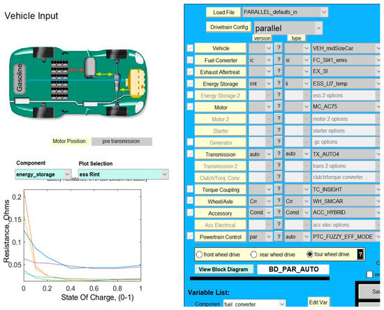
Figure 5.
The setup ADVISOR page of the input HEV midsize car.
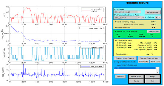
Figure 6.
UDDS driving cycle input profile.
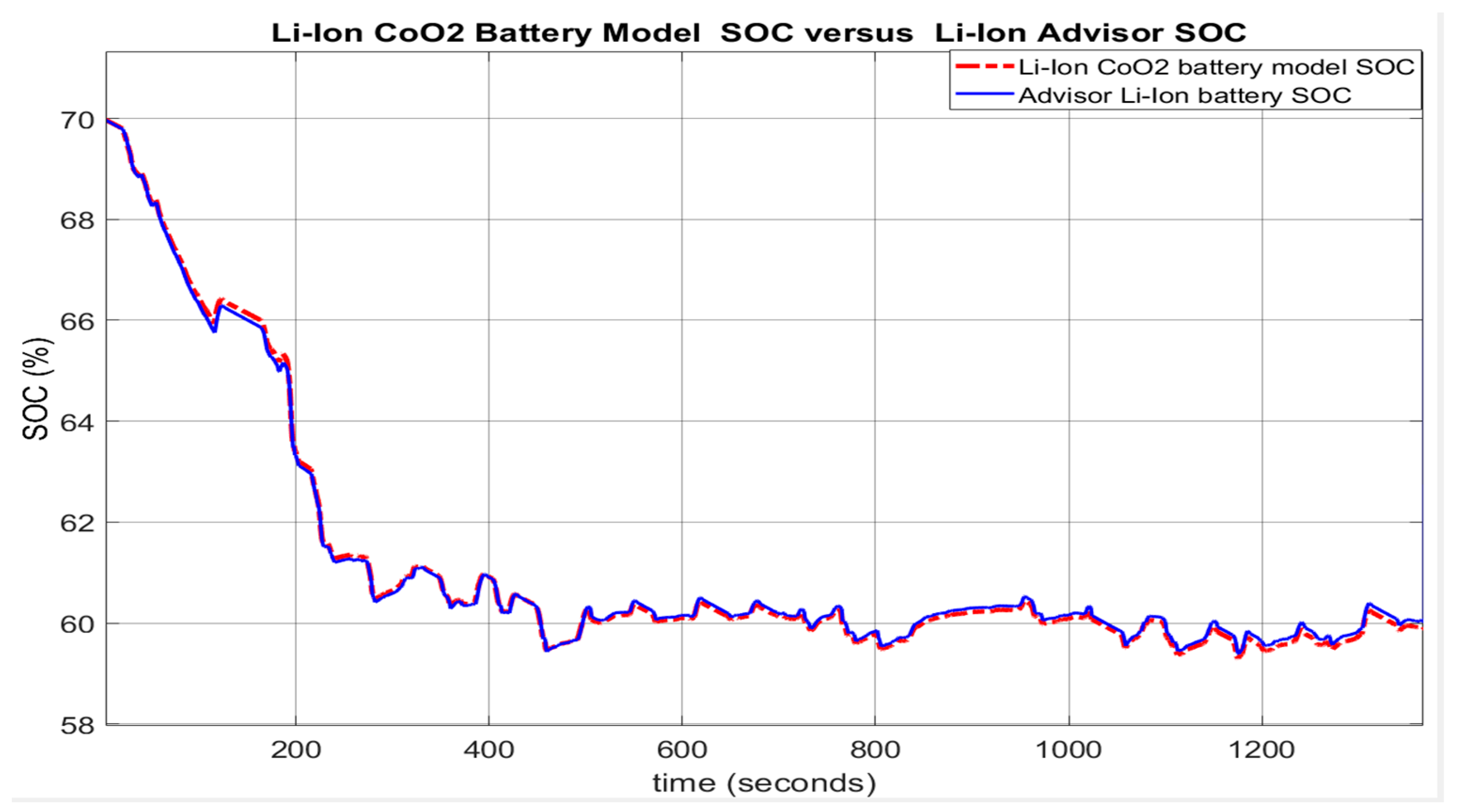
For performance comparison purposes, Figure 7 shows the corresponding SOC curves for the proposed Li-ion Co battery model design (red colour) and the ADVISOR SOC estimator (blue colour) on the same graph. The SOC simulations are performed for the same initial conditions (SOCini = 70%) and reveal an excellent SOC accuracy and an estimation error less than 2% between the battery model selection and NREL ADVISOR Rint battery model. The result confirmed by the second source from the first line of Table 3 (battery model vs. ADVISOR Rint model), for which the mean absolute error (MAE) is 0.0658. Other two sources can confirm the model validation by performing same comparisons for UDDS-EPA driving cycle test that will be developed in Section 3.3.2 with the statistical results shown in Table A1 from Appendix A. The third FTP driving cycle test will be developed in Section 3.3.3 and statistical results are shown in Table A2 from the same Appendix A.
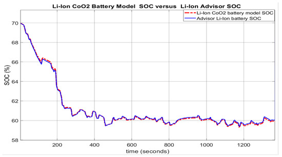
Figure 7.
The UDDS test on the ADVISOR 3.2 integrated MATLAB platform. SOC battery model versus Li-ion ADVISOR battery SOC.

Table 3.
AEKF and LOE SOC Estimators-statistical errors.
The results reveal an estimate value less than 2%, MAE = 0.0235 (Table A1) and MAE = 0.0285 (Table A2) respectively. The MATLAB simulation results of all three tests for UDDS, UDDS-EPA and FTP driving cycles, for same initial conditions show an excellent accuracy for adopted battery model versus ADVISOR Rint and an estimation error less than 2%, confirmed by the results from Table 3, Table A1 and Table A2 from Appendix A. Since from three different sources, the simulation results converge to an average error of less than 2% and show an accurate estimate value, we can conclude that these results validate the Li-ion Co battery. This outstanding result is encouraging to use the validated proposed battery model as a support for building “robust, accurate and reliable real-time battery estimators”, both developed in Section 3. Further, in Figure A2a,b shown in Appendix A, you can see the statistics obtained for the SOC generated by the proposed Li-ion Co battery model and for SOC estimated by the generic ADVISOR Rint Li-battery model. Figure 8 shows the Simulink model of the adopted generic model that implements the set of Equation (13).
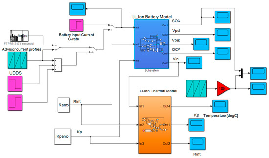
Figure 8.
Simulink generic selected battery model.
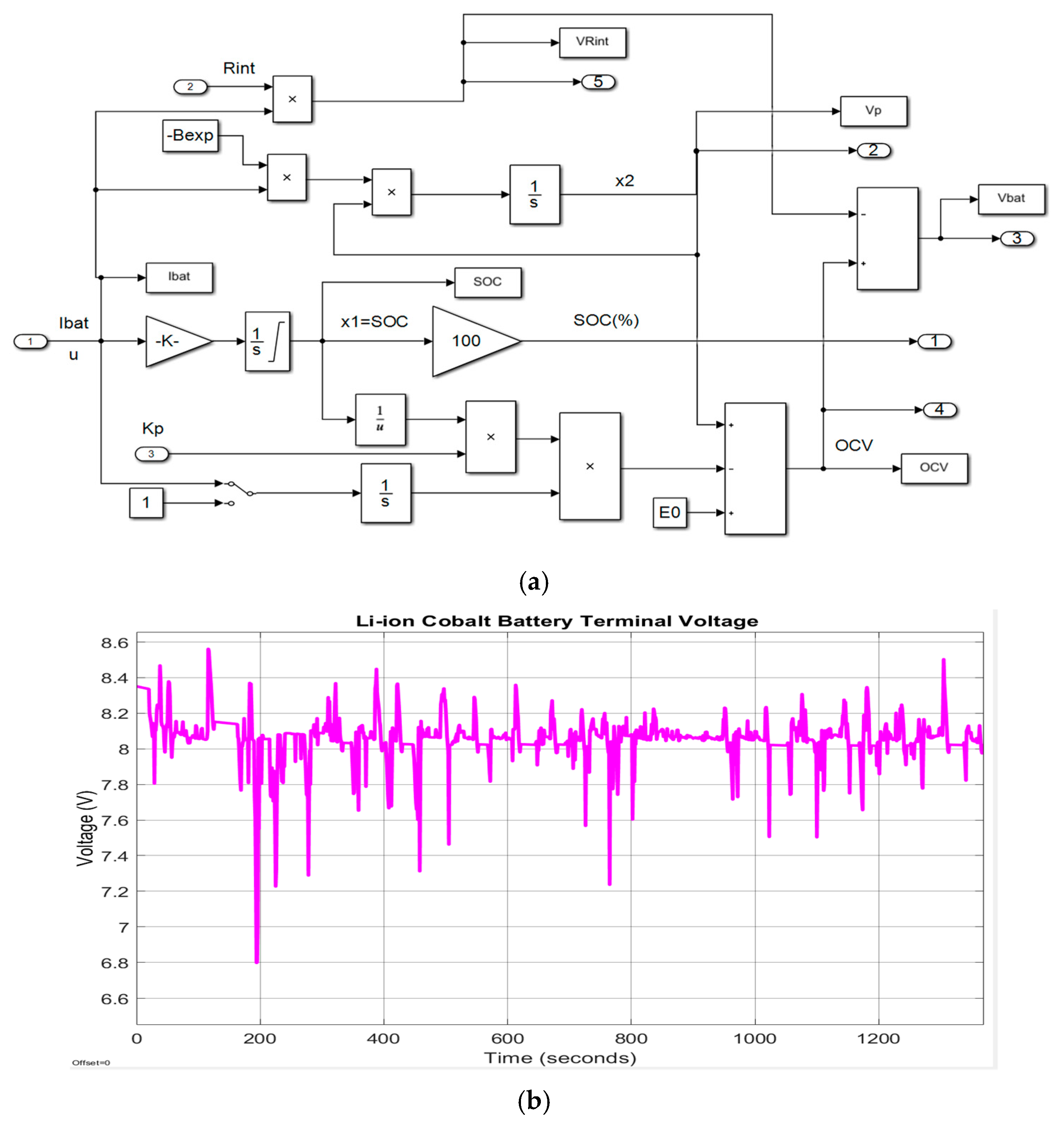
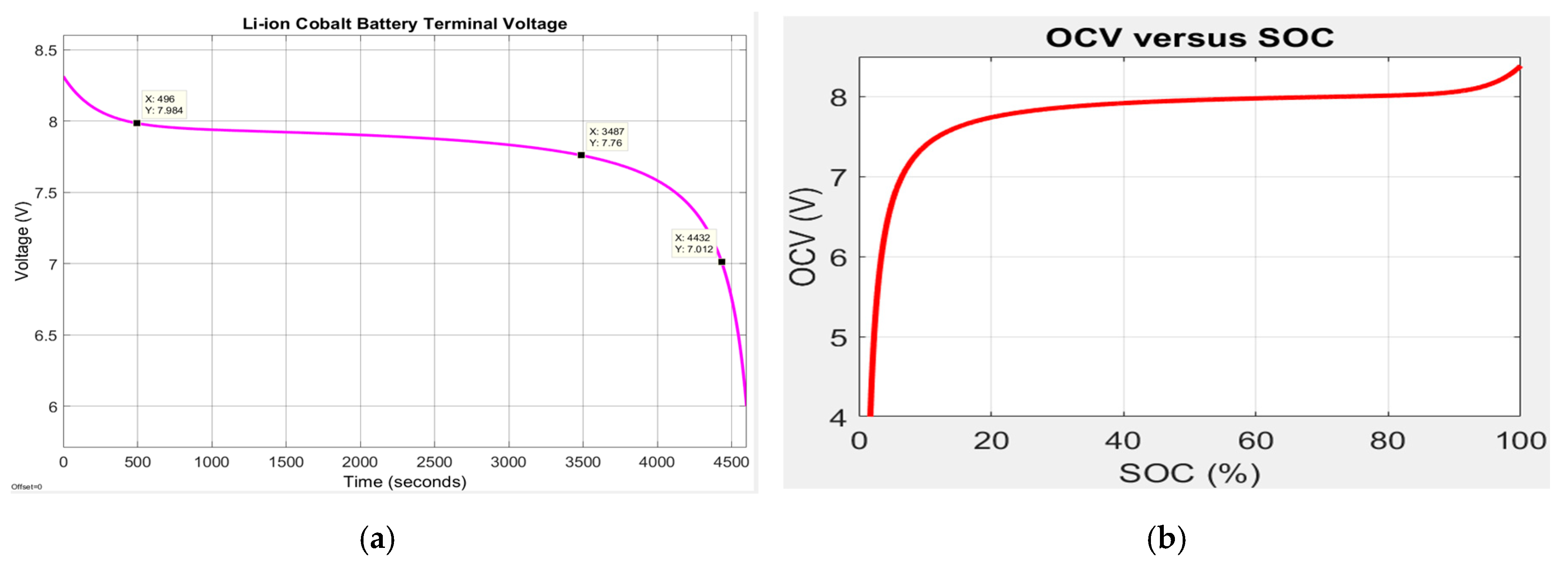
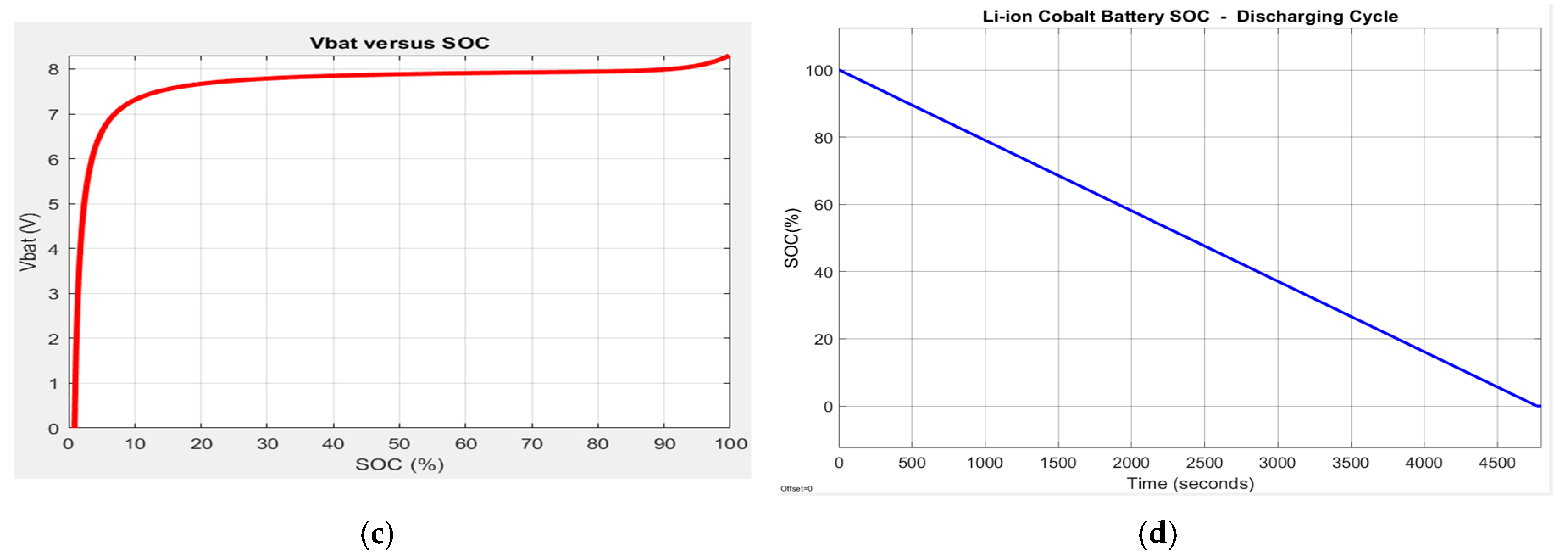
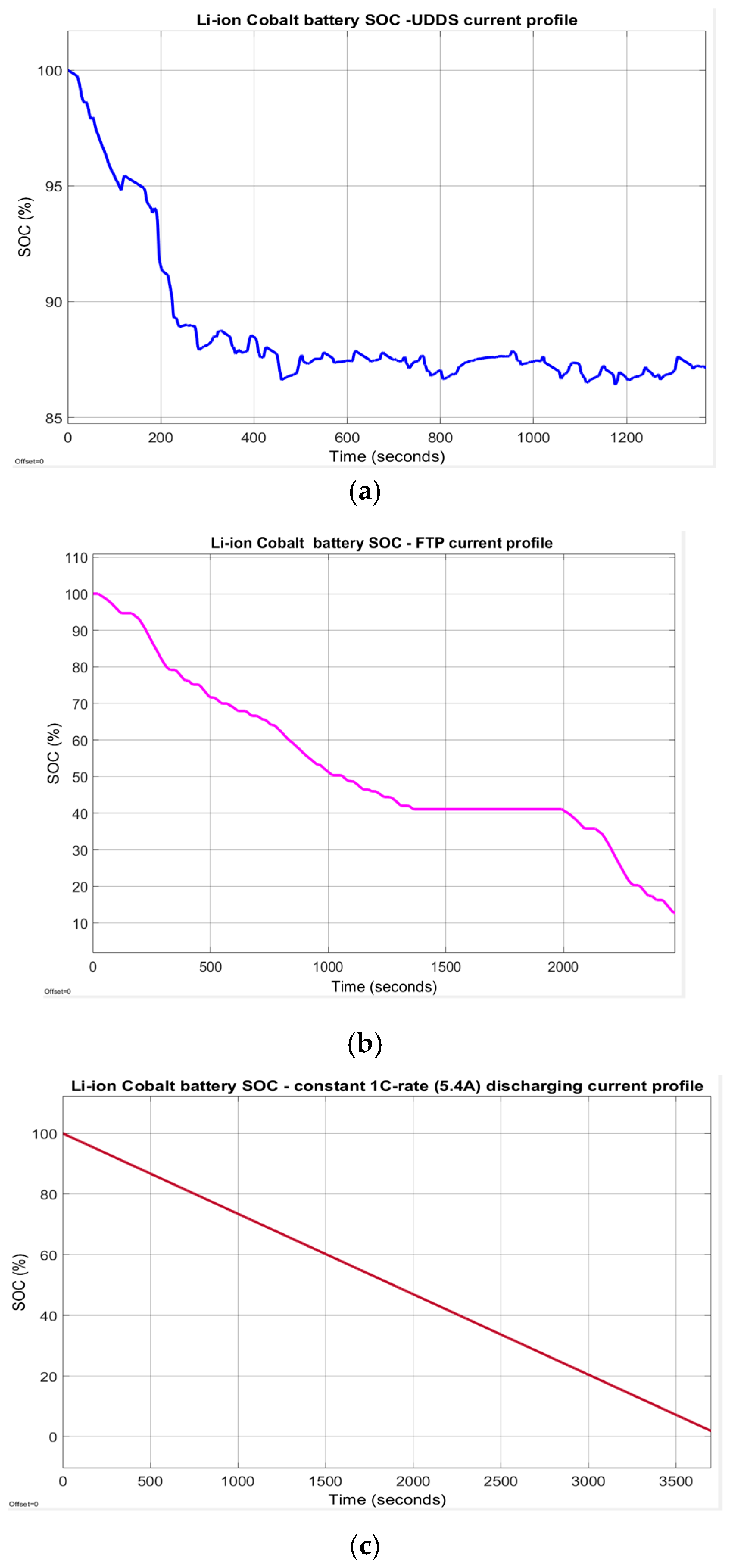
The block from the top side of Simulink diagram calculates the SOC, OCV and battery terminal voltage Vbatt, shown in detail in Figure 9a,b. For a constant discharging current of 1C-rate (5.4 A), the battery terminal voltage, the OCV-SOC battery characteristic, and SOC are represented in Figure 10a–d. Furthermore, the adopted battery model generates the SOC that is shown in Figure 11a–c for three different driving conditions, namely for a UDDS, an FTP-75 and a constant 1C-rate (5.4 A) discharging current.
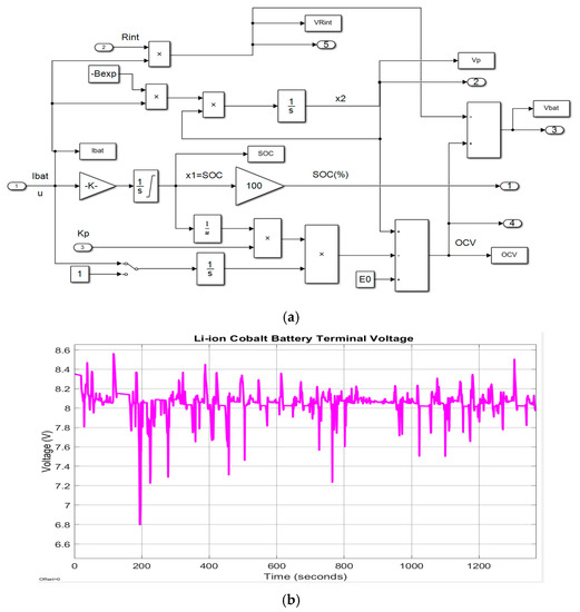
Figure 9.
(a) The detailed generic battery Simulink model; (b) The generic battery terminal voltage.
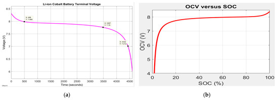
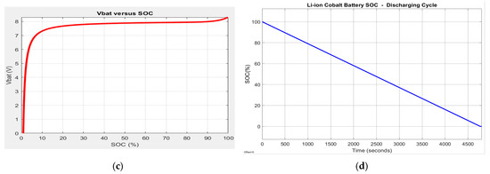
Figure 10.
The battery model full discharging cycle at 1C-rate (5.4 A); (a) battery terminal voltage; (b) OCV vs. SOC characteristic; (c) terminal voltage vs. SOC; (d) battery SOC.
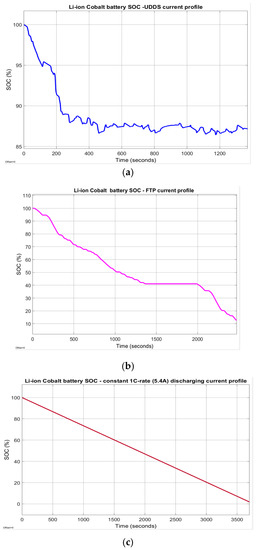
Figure 11.
Battery SOC for three different current profiles; (a) For UDDS driving cycle current profile; (b) For a FTP-75 current profile; (c) for a 1C-rate (5.4 A) discharging current profile.
It is worth mentioning that a 100 Ah rated pack capacity Li-ion battery model is integrated in a MATLAB-Simulink SimPower Systems library, very helpful to be used for designing and implementation of different HEVs and EVs powertrains configurations, such is suggested in the EV application shown in Figure A3 from Appendix A.
2.7. Li-Ion Cobalt Battery Thermal Model
The dynamics of thermal model block is described by the following equation:
where m—the mass of the battery cell [kg]; —the specific heat capacity [J/molK]; S—the surface area for heat exchange []; —the variable temperature of the battery cell [K]; —the ambient temperature [K]; —the value of internal resistance of the battery cell []; I(t)—the input charging and discharging profile current [A].
For simulation purposes, the battery temperature profile and the robustness of the proposed SOC battery estimators, are tested for the following approximative values, closed to a commercial battery type ICP 18,650 series:
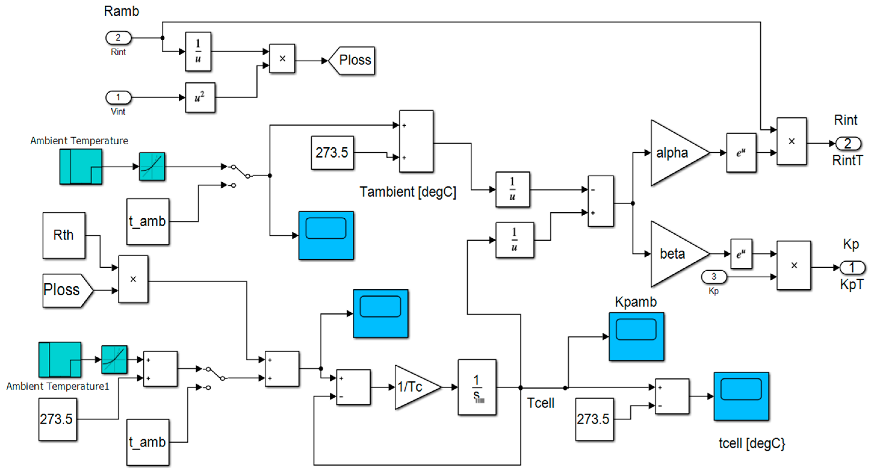
An accurate simplified thermal model is given in MATLAB R2019b library, at MATLAB/Simulink/Simscape/Specialized Power Systems/Electric Drives/Extra Sources/Battery, for a lithium-ion generic battery model, implemented in Simulink as is shown in Figure 12:
where —the internal temperature of the cell [°K] in complex s-domain (the Laplace transform). —thermal resistance, cell to ambient (°C/W). —thermal time constant, cell to ambient (s). -the overall heat generated (W) during the charge or discharge process [w]. —the ambient temperature set up by the user [K].
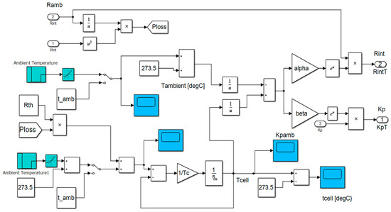
Figure 12.
The detailed Simulink diagram of the thermal model block.
The internal resistance and the polarization constant and respectively vary with respect to temperature according to Arrhenius relationships:
where Tref—the nominal ambient temperature, in K. α—the Arrhenius rate constant for the polarization resistance. β—the Arrhenius rate constant for the internal resistance.
For simulation purpose for implemented thermal block in Simulink, we use the following approximative values for the Li-ion battery thermal model parameters:
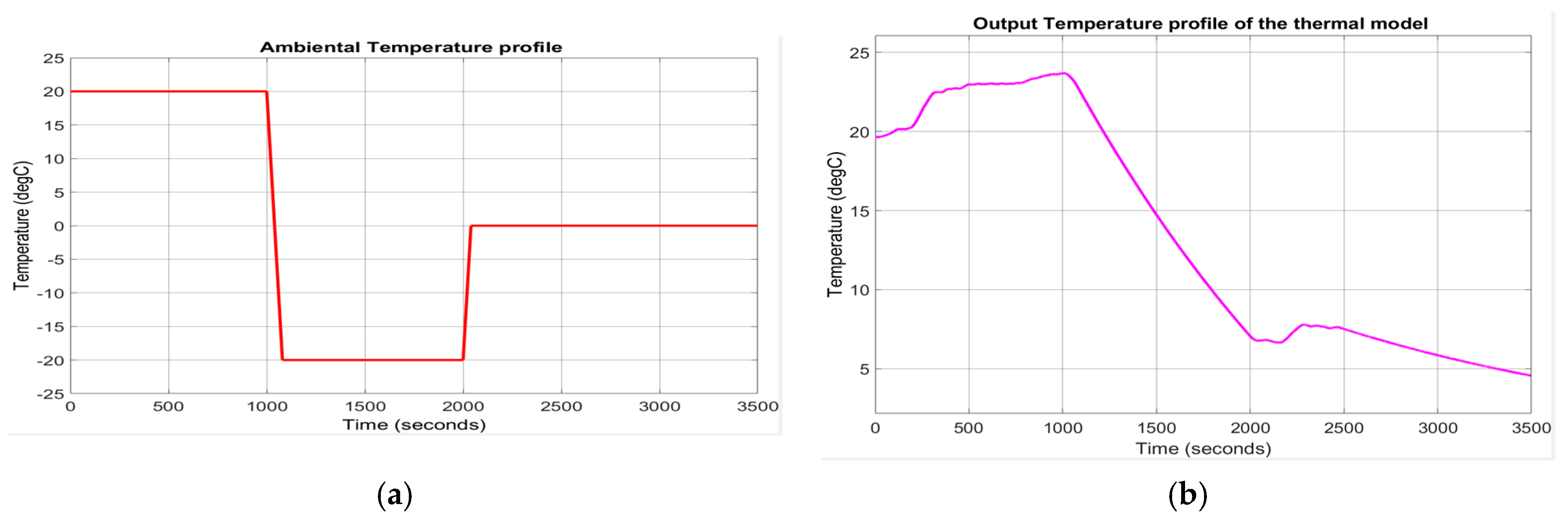
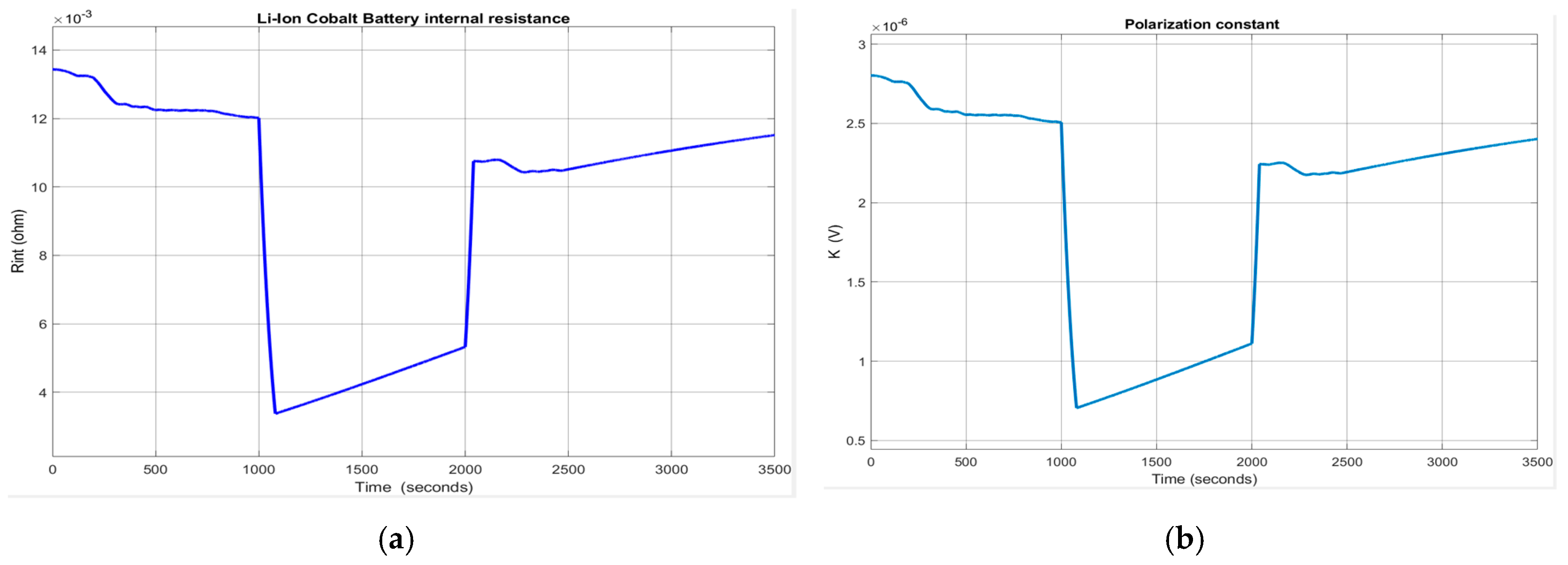
The ambient temperature profile and the output temperature of the Simulink thermal model described by the Equations (18) and (19) are shown in Figure 13a,b, respectively. The evolution of the internal resistance of the battery cell Rint (T) and of polarization constant K(T), at room temperature Tref = 293.15 , is shown in Figure 14a,b.

Figure 13.
(a) The ambient temperature profile; (b) The output temperature of the thermal model block.
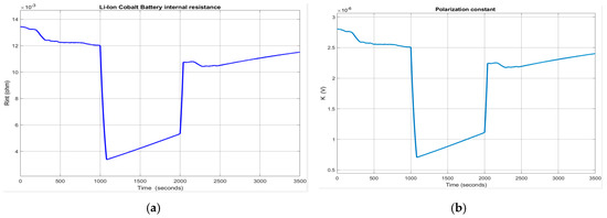
Figure 14.
(a) The internal battery Rint at ambient temperature (20 degC); (b) The polarization constant at ambient temperature (20 degC).
The output temperature of the thermal model for changes in ambient temperature is shown in Figure A4a, and the effects on internal battery resistance Rint and polarization constant K are presented in Figure A4b,c, shown in Appendix A.
3. Li-Ion Co Battery State of Charge Estimation Algorithms
Almost all BMS HEV/EV systems in the automotive industry have integrated emergency systems that indicate the available battery capacity. As the SOC is not directly measured, its estimation is required. For estimating SOC, several methods for estimating adaptive filtering are developed in the field literature, among which the Kalman filters are the most used. More details about battery modelling, linear and nonlinear Kalman filter estimators, especially for state and parameter estimation, can be found in [4,7,8,9,10,11,12,14,15,26,27,28,29,30,31,32,33,34,35,36,37]. For performance comparison purposes, in this actual study, we develop two well-suited real-time SOC estimators, namely an Adaptive Extended Kalman Filter (AEKF) with the process and measurement noises correction, and a linear observer estimator (LOE) with a constant Luenberger gain.
3.1. Li-Ion Cobalt Battery-Adaptive Extended Kalman Filter SOC Estimator
As we mentioned in the previous section, the most suitable method for estimating SOC in real-time is the Coulomb counting method. The main disadvantage of this estimation technique is the difficulty of “predicting” the most appropriate initial SOC value of the battery, which could lead to an increase in time of the SOC estimation error and to a new “SOC calibration” based on “OCV measurement” [5]. However, “it is tough to measure the battery OCV in real-time and, consequently, a small OCV error may lead to a significant battery SOC difference”, as is stated in [5].
Thus, one is thinking of improving the Coulomb metering method, a viable alternative is using an EKF SOC real-time estimator, suitable for a wide range of HEV/EVs applications. Besides, the adopted version of an adaptive EKF (AEKF) real-time estimator combines the advantages of both the Coulomb counting method and battery OCV calibration [5]. More precisely, the AEKF SOC estimator is an EKF, as is developed in detail in [7,8,10] with the performance improved in [5,30].
Additionally, the AEKF algorithm makes a recursive correction of the Gaussian process and measurement noises that simplifies the tuning procedure significantly. In [17], the correction is beneficial to calculate the Kalman gain of the AEKF SOC estimator, which leads to optimal results for the SOC estimation, as is shown in [5]. Furthermore, AEKF algorithm can improve its estimation performance by using “a fading memory factor to increase the adaptiveness for the modelling errors and the uncertainty of Li-ion battery SOC estimation, as well as to give more credibility to the measurements”, as is stated in [5,7].
As we mentioned in the previous section, the AEKF requires a dynamic state-space representation model of Li-ion Co battery, in order “to develop a simulation model for the emulation of a nonlinear battery” behaviour [17]. The AEKF algorithm is based on the linearized model of the battery, as is developed in [5,7,8,9,10,17,26]. In our research paper, for the case study, we adopt the AEKF algorithm developed in [17] and is presented briefly in Table 3. For more details, the reader can refer to the papers [7,8,9]. The discrete-time state-space representation of the generic Li-ion Co battery model, required to design and implement in real-time the AEKF SOC estimator, is given by the Equations (20) and (21), further simplified to a unidimensional SOC state-space discrete-time representation:
where , are the battery input current profile and terminal voltage at the discrete time k, = is the sampling time, set to 1 in MATLAB simulations. In this representation the state space Equation (17) and input-output Equation (18) depends only on SOC, the first equation is linear and the second one is highly nonlinear. The proposed algorithm AEKF follows the same steps such in [5,7,8,9] combined with the approach developed in [17], as is shown below:
AEKF SOC estimation algorithm steps:
[AEKF 1.1] Write Li-ion Co battery discrete-time nonlinear generic model equations:
[AEKF 1.2] Write the unidimensional Li-ion Co battery model in discrete-time state space representation:
where the process and measurement output are white uncorrelated noises of zero mean and covariance matrices and respectively, i.e.,
[AEKF 2] Initialization:
The initial value of SOC is estimated as a Gaussian random vector of the mean and covariance values given in (26).
For set
[AEKF 3] Linearize the Li-ion Co nonlinear dynamics and calculate the Jacobian matrices:
The nonlinear dynamics of Li-ion Co battery is linearized around the most recent estimation state value and respectively, considered as an operating point. The Jacobian matrices of the linearization are given by:
For do
[AEKF 4] Prediction phase (forecast or time update from ):
Remark: In this phase, the predicted value of the state vector is calculated based on the previous state estimate and the state covariance positive definite matrices and (unidimensional in the case study) are affected by a fading memory coefficient α.
[AEKF 5] Compute an updated value of Kalman filter gain:
[AEKF 6] Correction phase (analysis or measurement update):
The Li-ion Co battery SOC estimated state is updated when an output measurement is available in two steps:
[AEKF 6.1] Update the SOC estimated state covariance matrix:
[AEKF 6.2] Update the SOC estimated state variable:
[AEKF 7] Adaptive process and measurement noise covariance matrices correction in two steps:
For k >= L, the length of the window’s samples, compute:
[AEKF 7.1] Output variable error and the correction factor:
[AEKF 7.2] Measurement noise correction:
[AEKF 7.3] Process noise correction:
The AEKF estimator is easy to implement since its “recursive predictor-corrector structure that allows the time and measurement updates at each iteration” [5]. The tuning parameters of AEKF SOC estimator are the following: and , , the fading factor α and the window length L, obtained by a “trial and error” procedure based “on designer’s empirical experience” [5]. It is worth noting that step 7 of the estimation algorithm simplifies substantially the procedure of tuning parameters without to affect the AEKF algorithm convergence. Moreover, the covariance matrices and are chosen as positive definite diagonal matrices, and then during MATLAB simulations, both matrices are adaptively updated using the correction equations (33) and (34). For simulation purposes, to test the effectiveness of the AEKF SOC estimator we set up the Kalman filter estimator parameters for all three driving cycle profile tests to the same values, i.e., samples.
3.2. Li-Ion Cobalt Battery-Linear Observer SOC Estimator with Constant Gain
Linear and non-linear observers can estimate the states of the control systems. A linear observer estimator can be used to estimate SOC, as it is easy to adapt to the Li-ion Co battery model. Compared to AEKF SOC estimator performance, the proposed linear observer (LOE) SOC estimator seems to have a fast convergence rate and high estimation accuracy, as mentioned in [18]. It is easy for design a MATLAB/Simulink implementation. Besides, it is robust to changes in the initial value of SOC, to changes in the battery internal resistance and polarization constant due to temperature effects. Furthermore, it has a high capability of compensating the effects of nonlinearity and uncertainty exhibited by Li-ion Co battery model. The main drawback of LOE SOC is its inability to filter the measurement noise, so it is not robust to the measurement noise level compared to AEKF that has this great feature. The proposed linear observer relies on the determination of the appropriate feedback that achieves better SOC estimation accuracy. The following equations describe the dynamics of the linear observer estimator (LOE):
Thus, Equation (35) describes the dynamics of Li-ion Co battery generic model that is unidimensional and dependent only on battery SOC. In this development, the input-output battery terminal voltage equation is linearized around a SOCop battery operating point, retaining only the first order term of Taylor series:
In discrete time, the LOE battery SOC is described by the following equations:
where the values of the coefficients , , and depend on the linearization operating point . For example, if the operating point is = 60%, these coefficients get the following values: ,, and . The Equation (37) are showing that the current output battery terminal voltage and its future evolution are both determined solely by its current state SOC (k) and the battery current input u(k). If the battery generic model system Equation (37) is observable, then the output battery terminal voltage can be used to steer the SOC(k) state of the observer. After linearization, it is easy to see that the pair is observable, since , regardless of the battery operating point. The observer model of the physical system of the Li-ion Co battery is then typically derived from the Equation (37). Additional terms may be included in order to ensure that, on receiving successive measured values of the Li-ion Co battery u(k) = i(k) input and output, the model’s state converges to of the battery. In particular, the output of the observer may be subtracted from the battery output and then is multiplied by a constant gain L to produce a so-called Luenberger observer, defined by the following equations:
The linear observer SOC estimator is asymptotically stable if the SOC state error:
For a Luenberger observer, the SOC state estimation error satisfies the following relationship:
The asymptotically condition (41) is satisfied only if (A-LC) is a Hurwitz matrix, so all the eigenvalues of this matrix are located in z-plane inside of the unit circle |z| = 1. For an unidimensional system, such in our case, A-LC must satisfies the relationship:
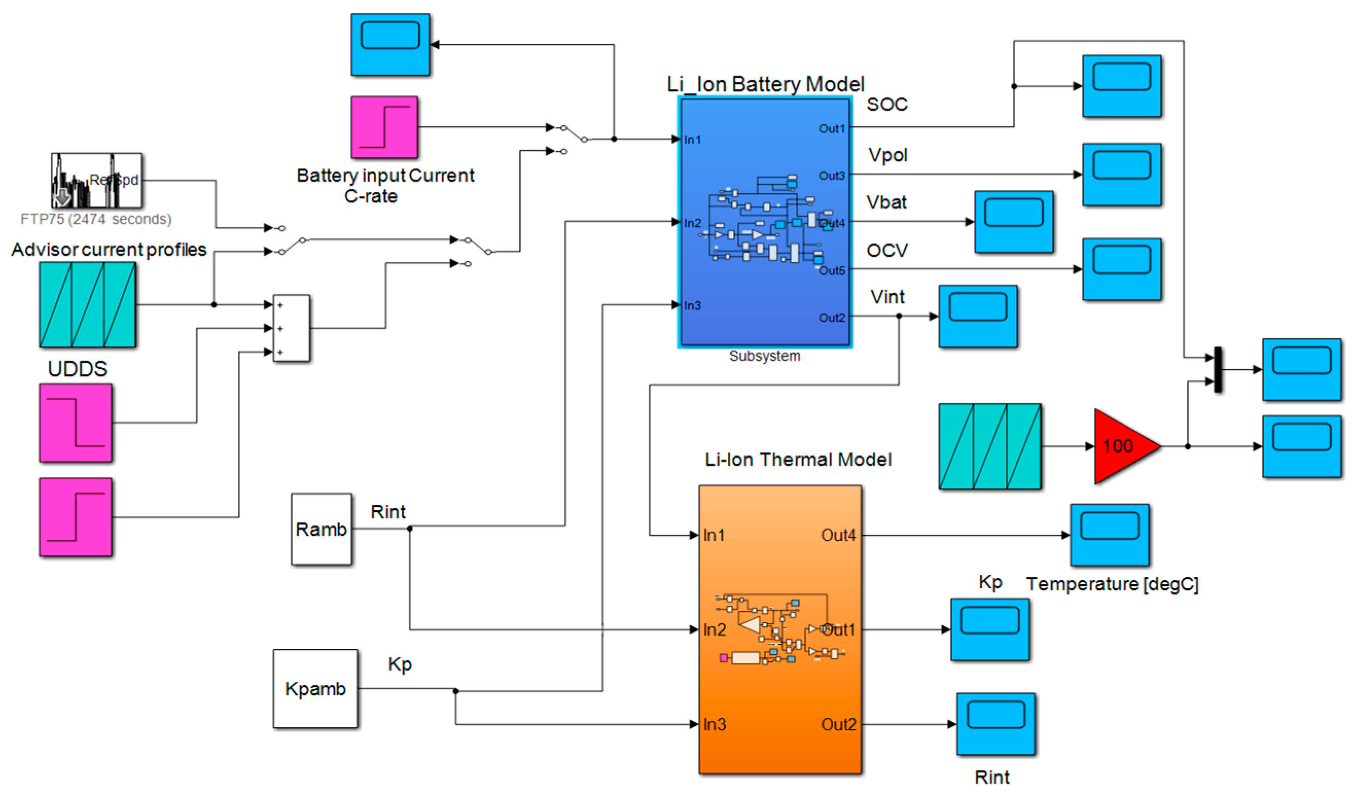
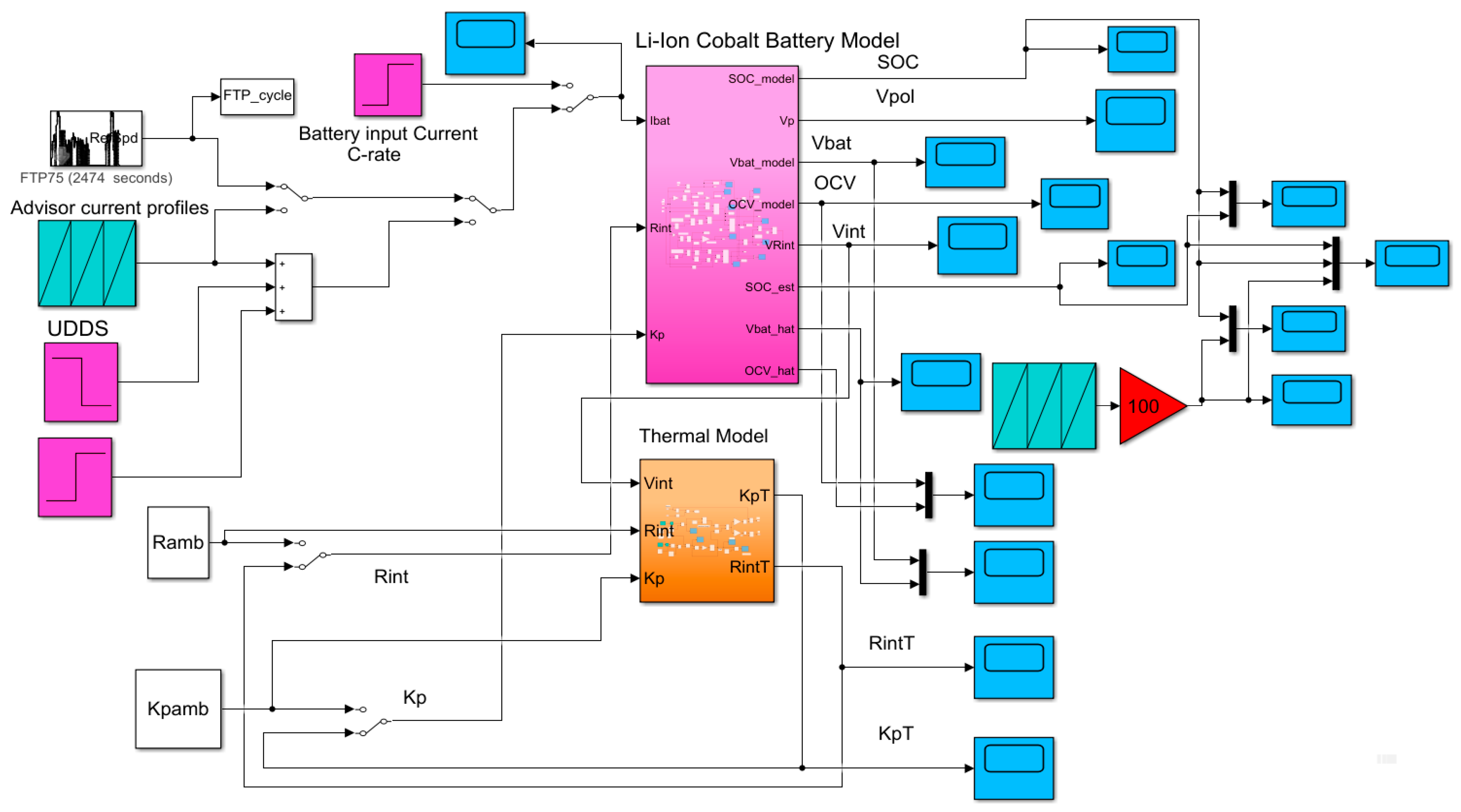
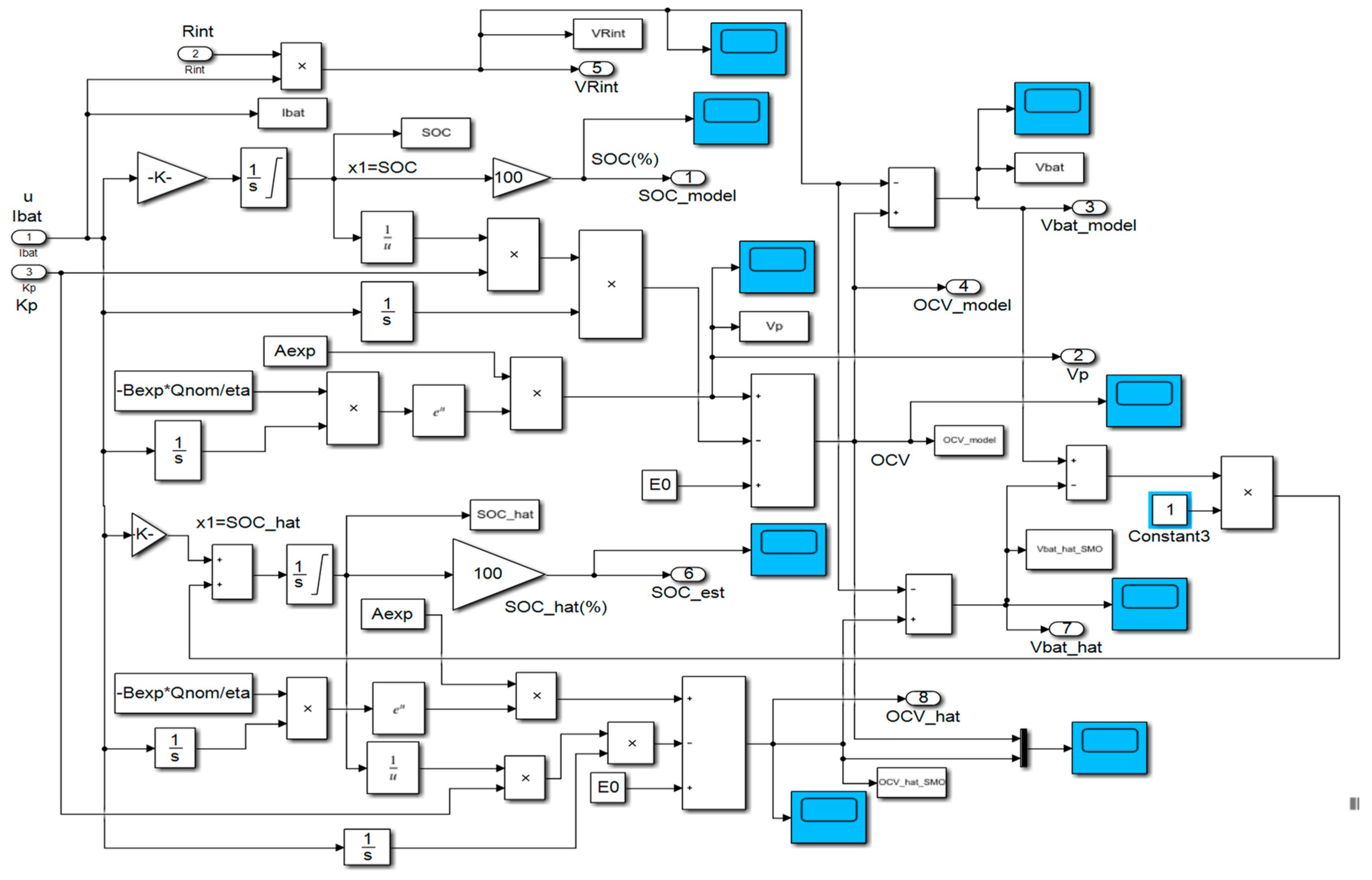
For MATLAB simulations L is set to 1, 10, and 100 to analyze the performance of the LOE estimator in terms of convergence speed, robustness and SOC estimation accuracy for same driving conditions tests, UDDS, UDDS-EPA and FTP-75, like the AEKF SOC estimator developed in the previous subsection. The Simulink models of the LOE SOC, Li-ion Co battery model, thermal model block and the input driving cycles current profiles are shown in Figure 15. The battery model and the LOE SOC estimator block is detailed in Figure 16, and the Simulink model of thermal block is shown in Figure 12.
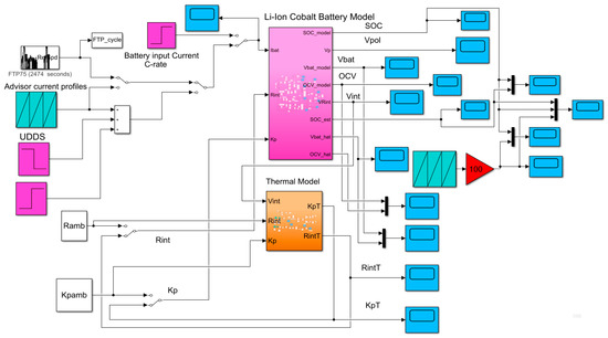
Figure 15.
The Simulink diagram of the combined Li-ion Cobalt battery model and LOE block located to the top side and, the Simulink diagram of thermal model block located in the bottom side.
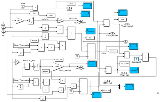
Figure 16.
The detailed Simulink diagram of the combined Li-ion Co battery and LOE models.
3.3. Real-Time MATLAB Simulation Results
In this section, an extensive number of simulations, conducted on MATLAB software platform, is performed to validate the battery model and to analyze the performance of both proposed AEKF and LOE SOC estimators. The performance of both, AEKF and LOE SOC estimators is analyzed in terms of accuracy, robustness, convergence speed and real-time implementation simplicity. Robustness is tested for changing driving conditions by performing tests based on each of the three most commonly used driving cycle profiles provided in the ADVISOR-MATLAB platform, namely UDDS, UDDS-EPA and FTP described in Section 2. Furthermore, for each driving cycle profile, the robustness of both SOC estimators are testing the following four scenarios:
- ○
- R1-scenario—changes in SOCini from 70% for UDDS and UDDS-EPA, 80%-FTP, driving cycles tests to:
- ○
- R11—for SOCini = 100%
- ○
- R12—for SOCini = 40%
- ○
- R2-scenario—changes in SOC initial value and in measurement sensor noise level
- ○
- R21—for SOCini = 100%, noise measurement level σ = 0.01(increased from 0.001)
- ○
- R22—for SOCini = 40%, noise measrement level, σ = 0.01(increased from 0.001)
- ○
- R3-scenario: changes in SOC initial value and in the value of the battery nominal capacity due to aging and/or temperature effects.
- ○
- R31—for SOCini = 100%, Qnom = 2.7 Ah (decresed from 5.4 Ah)
- ○
- R32—for SOCini = 40%, Qnom = 2.7 Ah (decresed from 5.4 Ah)
- ○
- R4-scenario: changes in SOC initial values and temperature effects on internal resistance Rint and on polarization constant K
- ○
- R41—for SOCini = 100%, Rint = Rint(T) changes from Rint = 0.01333 [Ω], K = K(T) changes from K = 0.0099892 [V]
- ○
- R42—for SOCini = 40%, Rint = Rint(T) changes from Rint = 0.01333 [Ω], K = K(T) changes from K = 0.0099892 [V]
Also, the statistical errors in terms of standard deviation (MATLAB command std, σ), root mean squared error (RMSE), mean squared error (MSE) and mean absolute error (MAE) defined for each driving cycle test by the Equations (42)–(44), are summarized in one table.
.
3.3.1. Test 1-UDDS Driving Cycle Profile
A. Li-ion Co generic model accuracy performance
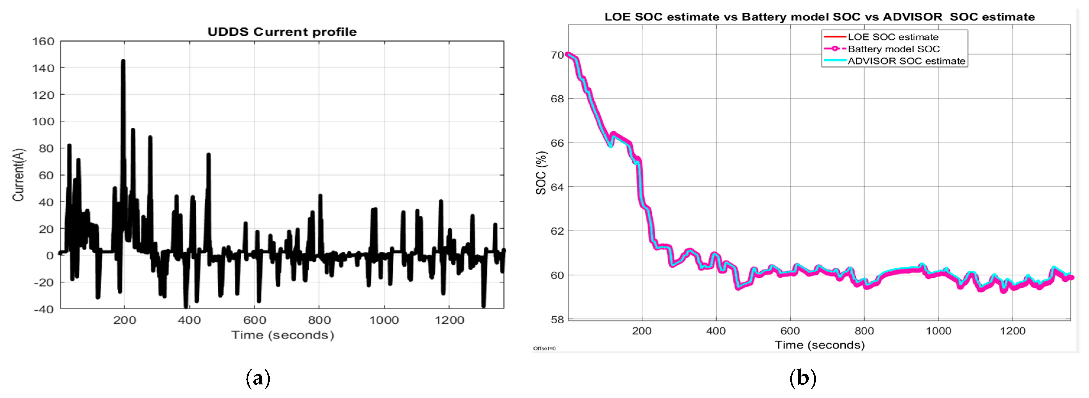
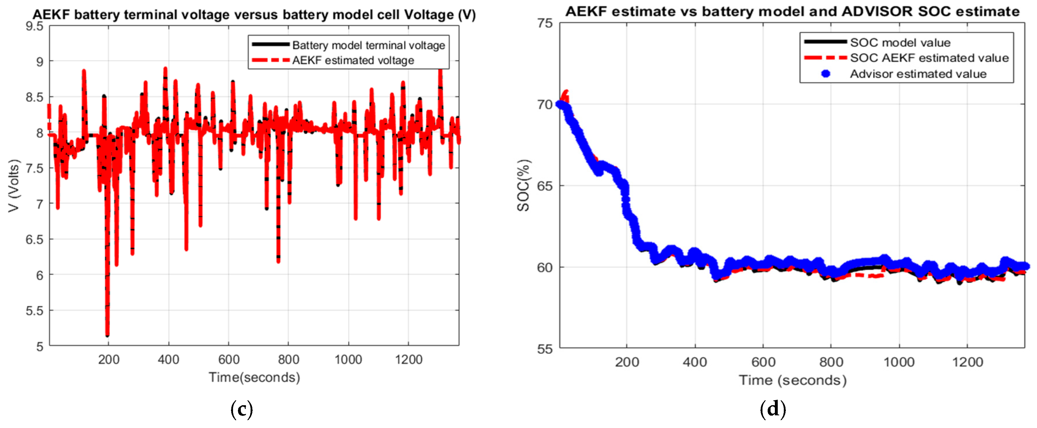
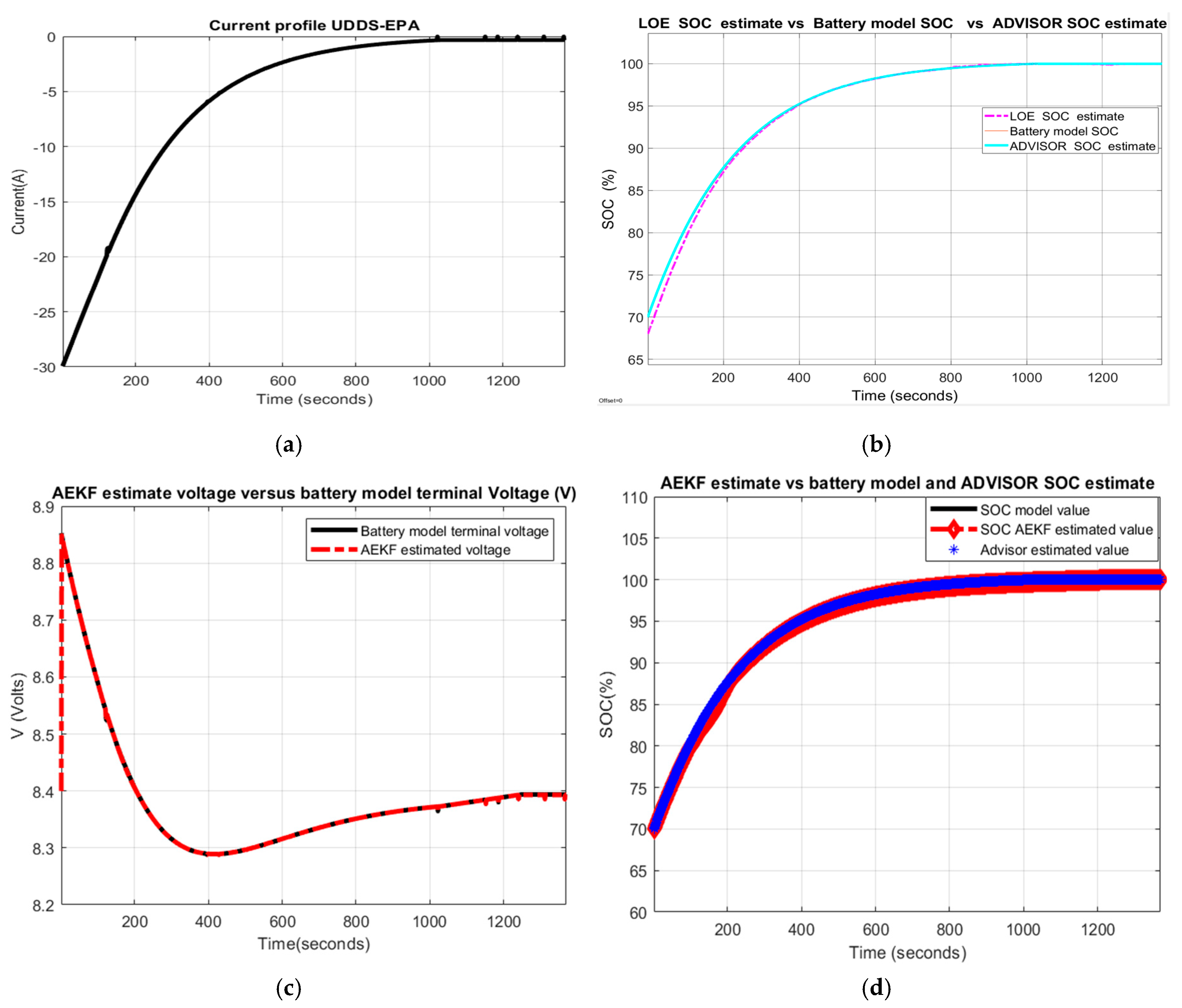
In Figure 17 the following MATLAB simulation results are shown:
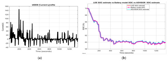
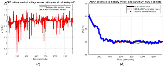
Figure 17.
Li-ion Co battery model SOC accuracy performance (a) The UDDS current profile; (b) LOE SOC estimate vs. battery model SOC and ADVISOR SOC estimate; (c) AEKF estimate terminal voltage versus battery model terminal voltage; (d) AEKF SOC estimate versus battery model SOC and ADVISOR SOC estimate.
- (a)
- UDDS driving cycle current profile for SOCini = 70%
- (b)
- LOE battery SOC estimate versus the battery model SOC and ADVISOR SOC estimate
- (c)
- AEKF battery terminal voltage estimate versus battery cell model terminal voltage
- (d)
- AEKF battery SOC estimate versus battery model SOC and AVISOR SOC estimate
The simulation results reveal that the battery SOC is very accurate with respect to ADVISOR SOC estimate for same SOC initial value, like in Section 2.6.4. Also, the AEKF and LOE SOC estimators are very accurate compared to battery model SOC. Additionally, the Figure 17c reveals a strong ability of the AEKF SOC estimator to predict the battery terminal voltage.
B. Robustness of AEKF and LOE SOC Estimators
- R1-scenario
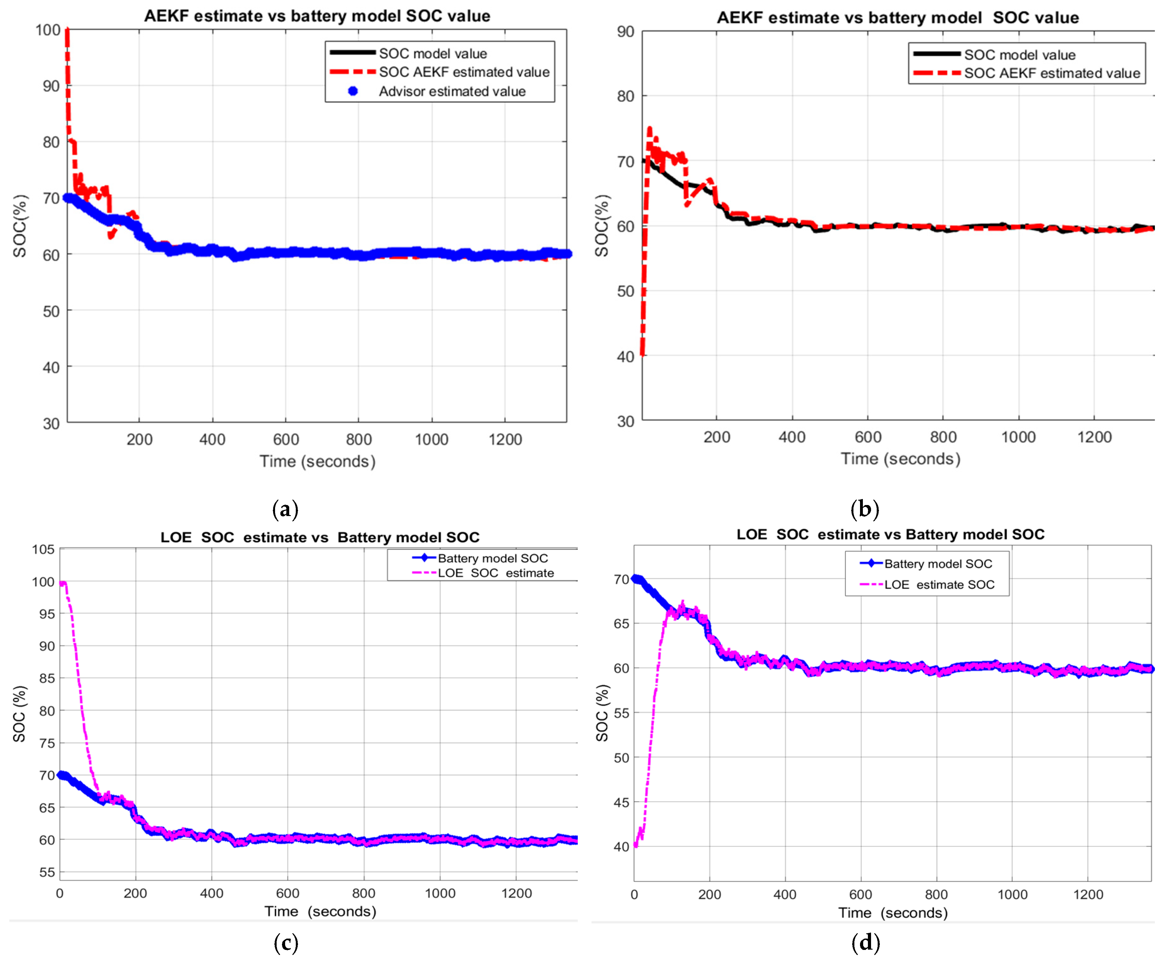
A great robustness of AEKF and LOE SOC estimators for this scenario is shown in Figure 18a,c, for R11, and in Figure 18b,d for R12.
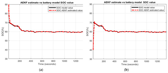
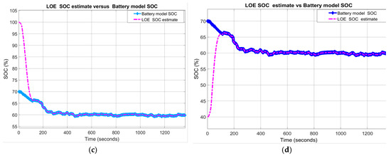
Figure 18.
SOC Estimators robustnsess-Scenario R1; (a) AEKF for R11; (b) AEKF for R12 (c) LOE for R11; (d) LOE for R12.
- R2-scenario
The MATLAB simulation results shown in Figure 19a–d indicate a great robustness of AEKF SOC estimator compared to LOE SOC.
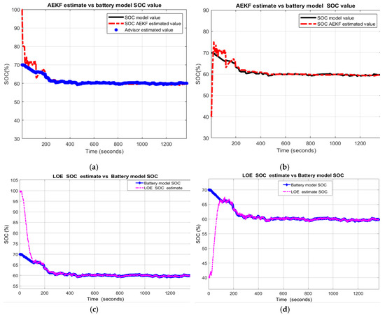
Figure 19.
The robustness of AEKF and LOE SOC estimators-Scenarion R2 (a) AEKF for R21; (b) AEKF for R22; (c) LOE for R21 (d) LOE for R22.
The AEKF SOC estimator has a great ability to filter the measurement noise, thus AEKF SOC estimator outperforms the LOE SOC regarding the robustness performance to changes in noise level.
- R3-scenario
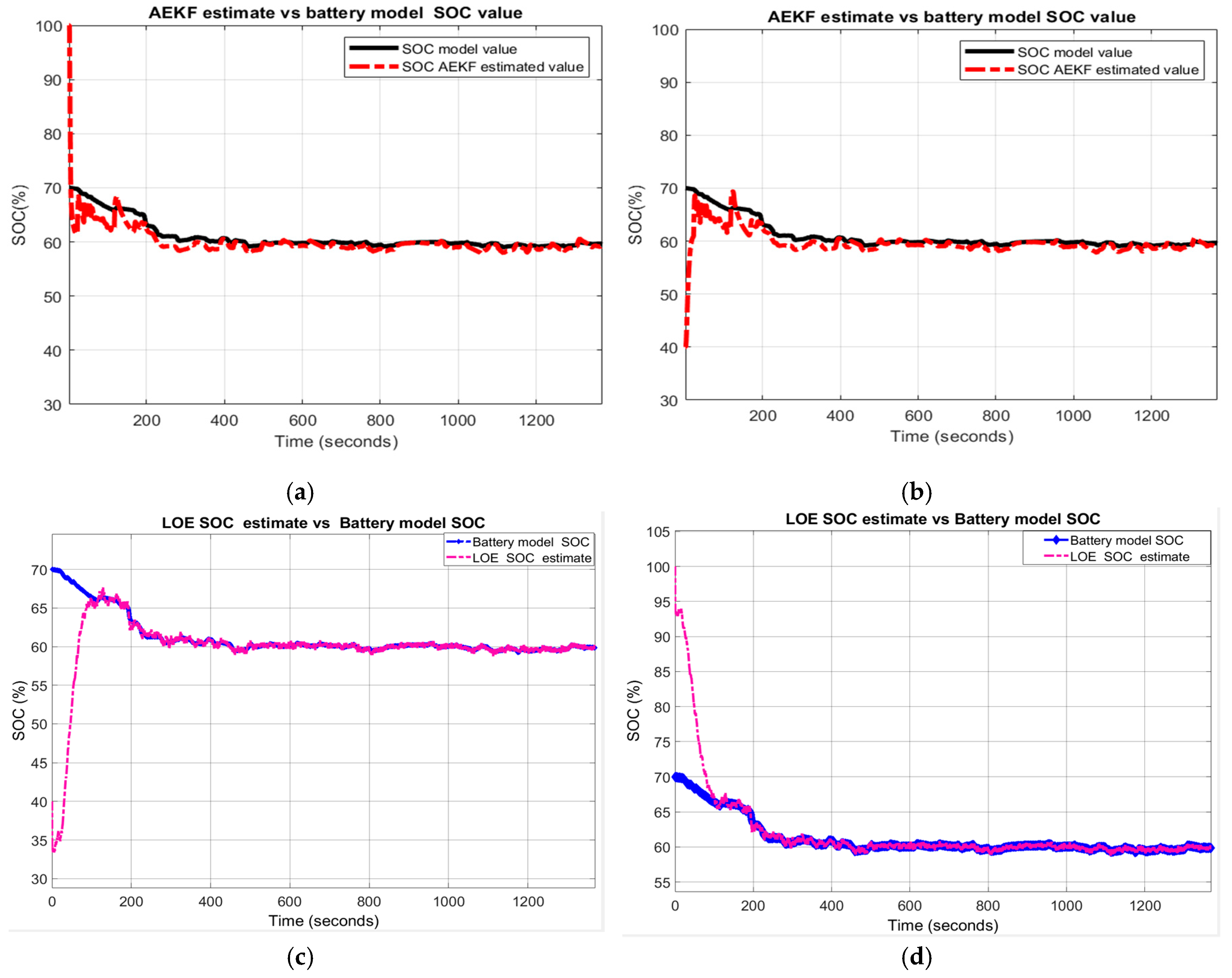
About the MATLAB simulations shown in Figure 20a–d it is worth highlighting the great robustness performance for both SOC estimators for this scenario.
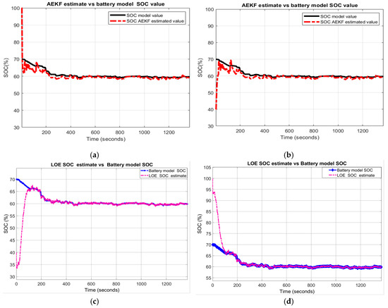
Figure 20.
The SOC estimators’ behaviour for R3-scenario (a) AEKF for R31; (b) AEKF for R32; (c) LOE SOC for R31; (d) LOE SOC for R32.
- R4-scenario
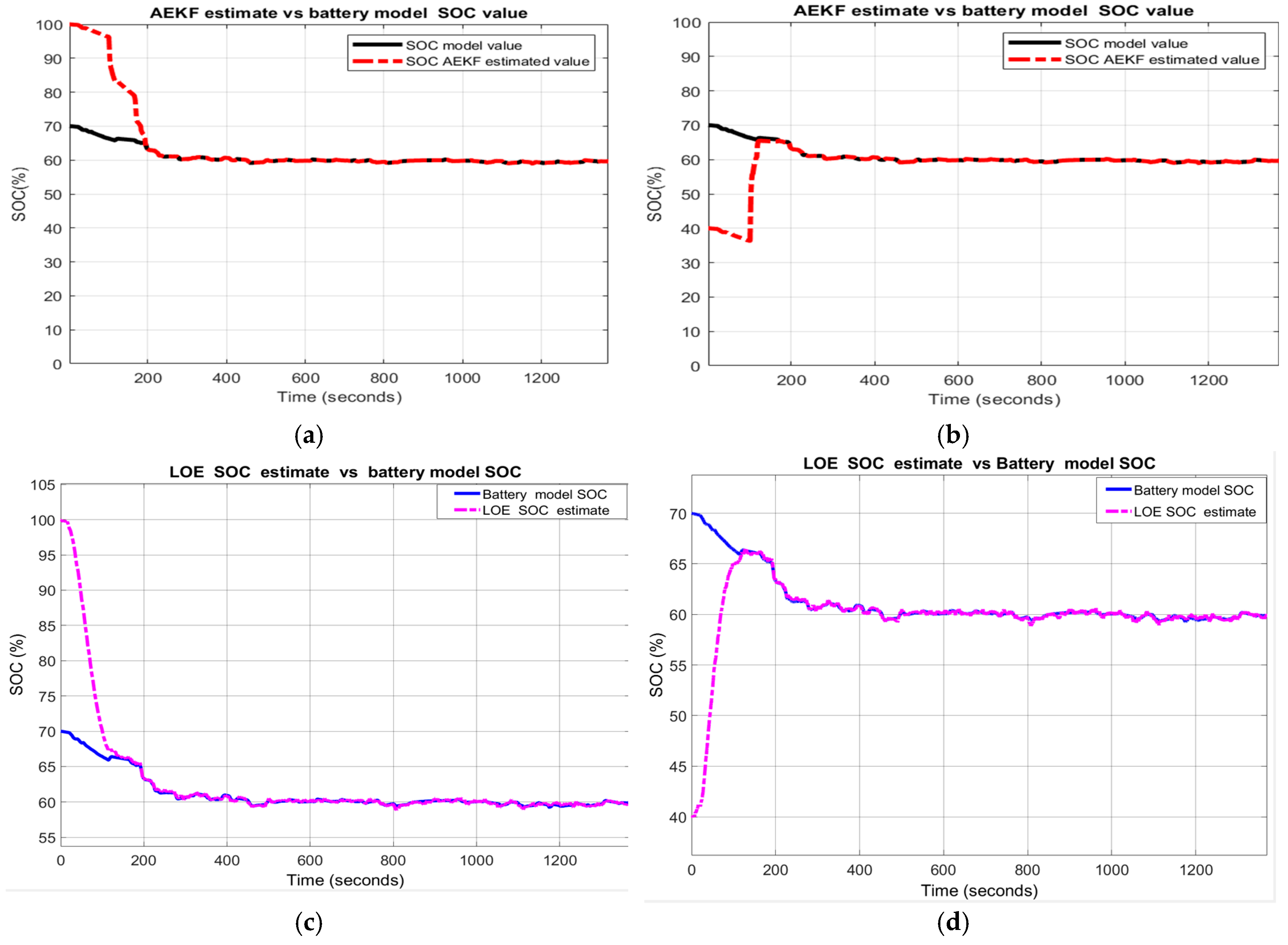
The output temperature profile of thermal model and the effects of temperature changes on the internal resistance Rint and polarization constant are shown in Figure A4. For this scenario, the MATLAB simulation results depictured in Figure 21a–d show an excellent robustness performance for both SOC estimators.
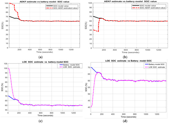
Figure 21.
AEKF and LOE SOC estimators robustness performance for R4-scenario; (a) AEKF for R41; (b) AEKF for R42; (c) LOE SOC for R41; (d) LOE for R42.
The statistical errors corresponding to all four scenarios developed for UDDS driving cycle test are summarized in Table 3.
The results of statistical errors performance analysis for all scenarios from Table 3, for UDDS driving cycle test, indicate that the AEKF SOC estimator surpasses the LOE SOC estimator in the competition for robustness performance.
3.3.2. Test 2: UDDS-EPA Charging Current Profile
A. Cobalt Li-ion generic model accuracy and validation
The MATLAB simulation results are shown in Figure 22:
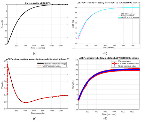
Figure 22.
Li-ion Co battery model SOC accuracy performance and validation; (a) UDDS-EPA driving cycle; (b) LOE SOC estimate vs. battery model SOC and ADVISOR SOC estimate; (c) AEKF battery terminal voltage estimate vs. battery model terminal voltage; (d)AEKF SOC estimate vs. battery model SOC vs. ADVISOR SOC.
- (a)
- UDDS-EPA driving cycle current profile
- (b)
- LOE SOC estimate versus battery model SOC and ADVISOR SOC estimate
- (c)
- AEKF battery terminal voltage
- (d)
- AEKF SOC estimate versus battery model SOC and ADVISOR SOC estimate
- (e)
- A great SOC accuracy of battery model versus ADVISOR SOC estimate is revealed in Figure 22b.
Like UDDS driving cycle, the MATLAB simulation results presented in Figure 22b,d reveal that the Li-ion Co battery model fits very well, within a 2% SOC error, the experimental setup ADVISOR-MATLAB platform SOC estimate. So, once again these results certainly confirm the validity of the generic lithium-ion cobalt battery model.
B. Robustness of AEKF SOC Estimator
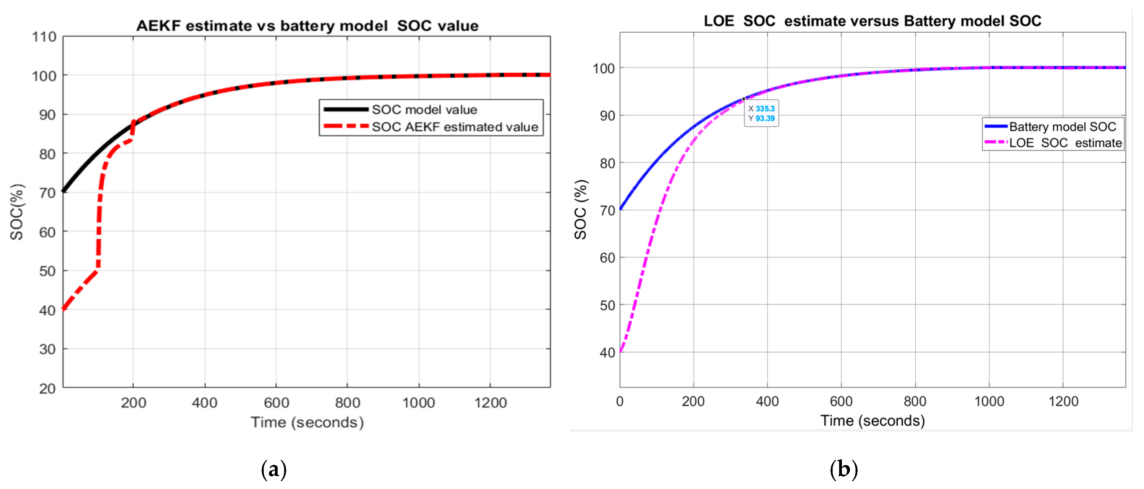
To keep the manuscript lenght reasonable, for the second driving cycle test, we show only the results for SOCini = 40%, i.e., for R12, R22, R32, and R42-scenarios.
- R1-scenario
The MATLAB simulation results shown in Figure 23a,b indicate an excellent robustness performance for both SOC estimators.
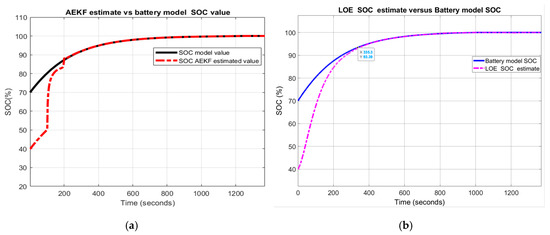
Figure 23.
The robustness of AEKF and LOE SOC estimators for R1-scenario; (a) AEKF for R12 (b) LOE for R12.
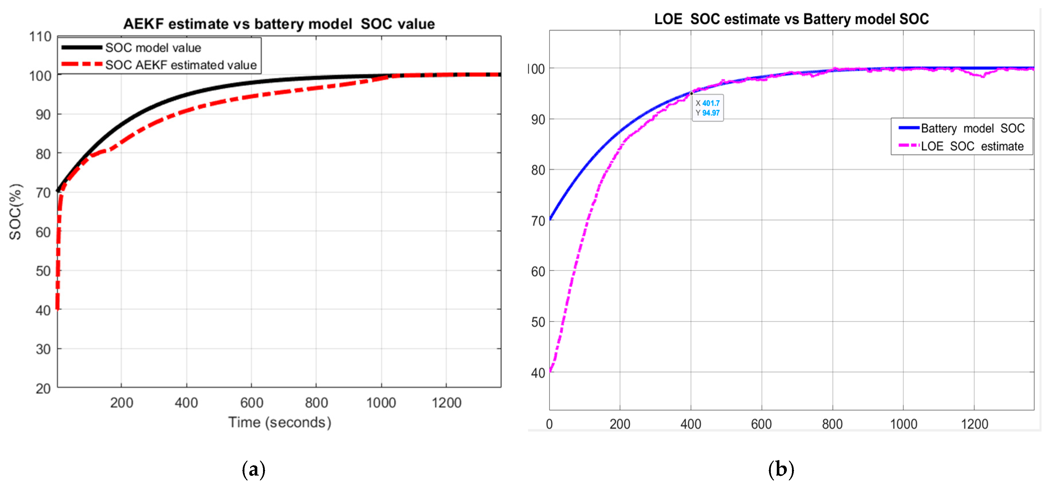
- R2-scenario
A great robustness for both SOC estimators for this scenario and R22 case is also shown in Figure 24a,b.
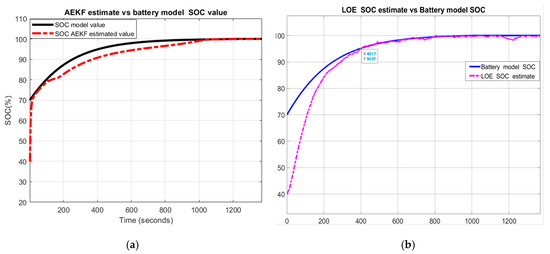
Figure 24.
The robustness of AEKF and LOE SOC estimators for R2-scenario; (a) AEKF SOC for R22 (b) LOE SOC for R22.
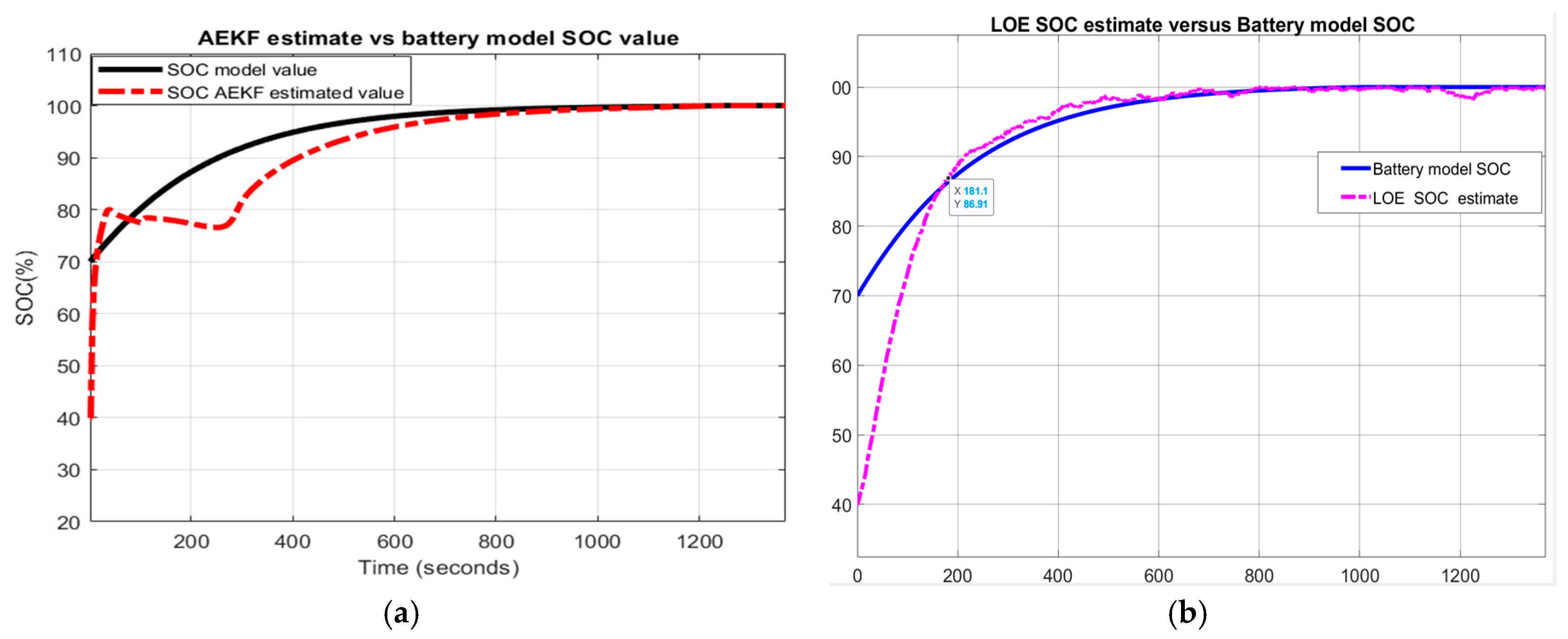
- R3-scenario
The MATLAB simulation results depicted in Figure 25a,b reveal a great robustness performance for the AEKF SOC estimator compared to the LOE SOC estimator that has small changes in SOC estimate accuracy.
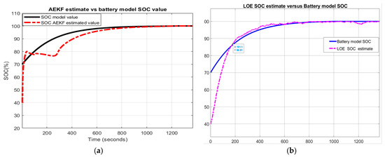
Figure 25.
Robustness performance of AEKF and LOE SOC estimators for R3-scenario; (a) AEKF SOC for R32; (b) LOE SOC for R32.
- R4-scenario:
For this scenario is considered the output temperature profile of thermal model and the effects of temperature changes on the internal resistance Rint and polarization constant K shown in Figure A4. The MATLAB simulation results of AEKF and LOE SOC estimation robustness performance are presented in Figure 26a,b.
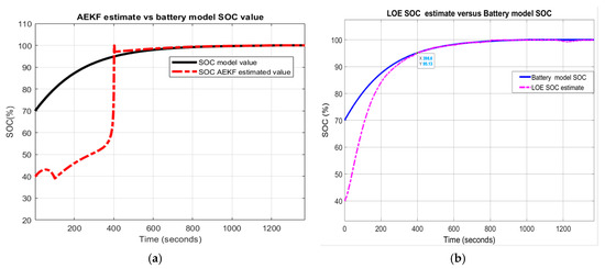
Figure 26.
Robustness of AEKF and LOE SOC estimators for R4-scenario (a) AEKF SOC for R42; (b) LOE SOC for R42.
For this scenario, the simulation results shown in Figure 26 indicate a great robustness performance for both SOC estimators. The statistical errors RMSE, MSE, MAE and standard deviation are summarized in Table A1 in Appendix A.
Like UDDS, the result of the performance analysis, for all the scenarios included in Table A1, indicates once again that the AEKF SOC estimator remains the most suitable SOC estimator as compared to LOE SOC estimator.
3.3.3. Test 3: FTP-ADVISOR Driving Cycle Current Profile
A. Battery model SOC accuracy and model validation
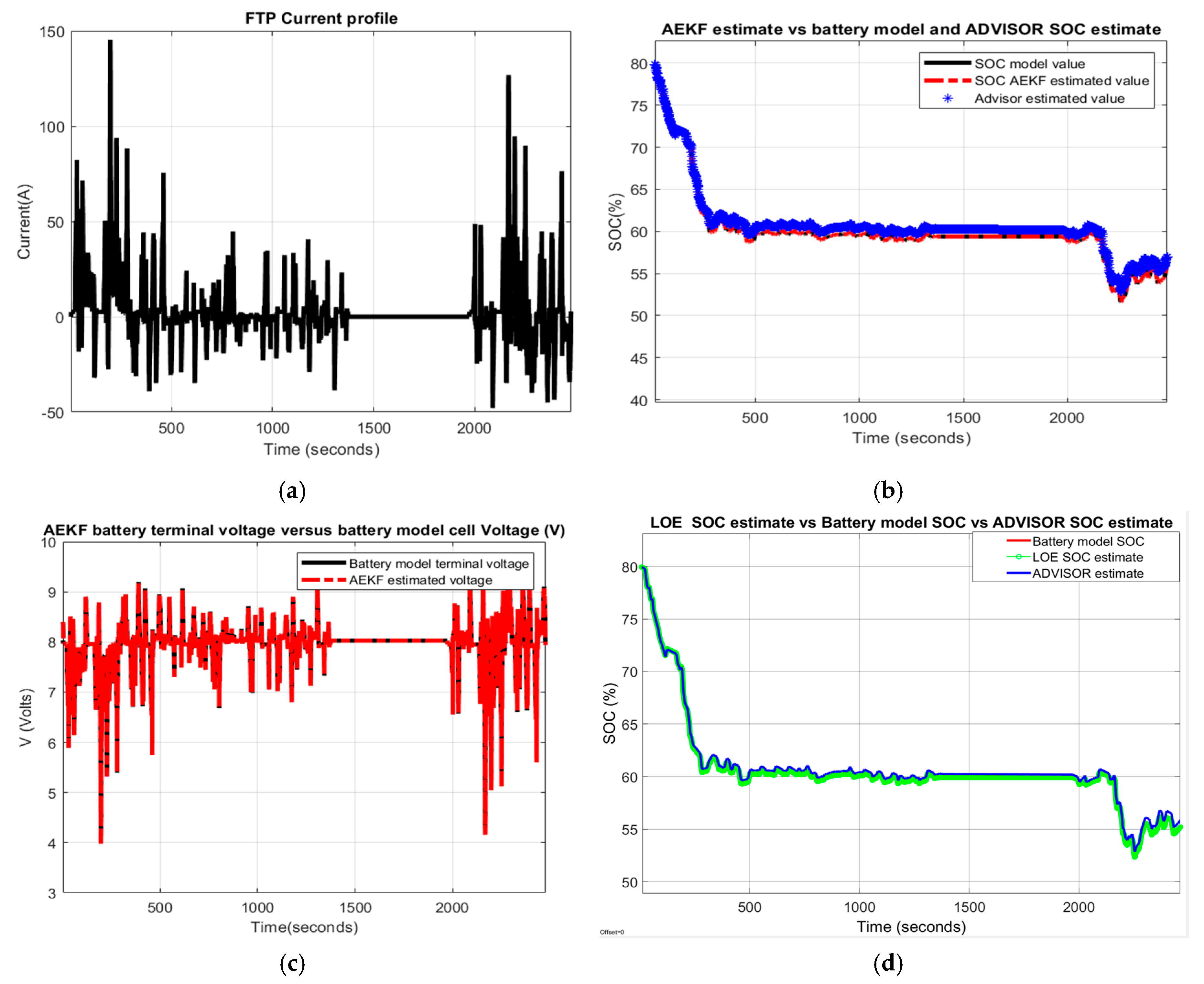
The FTP driving cycle current profile for testing the battery is shown in Figure 27a. For generic battery model validation, the AEKF SOC estimate, the Li-ion Co battery model SOC and the ADVISOR-MATLAB Rint Li-battery SOC estimate are shown on the same graph in Figure 27b.
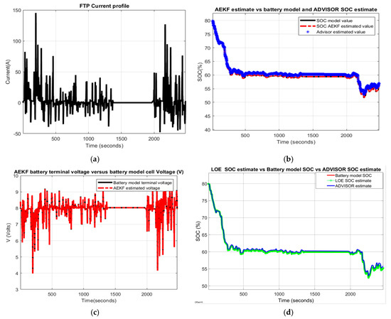
Figure 27.
Li-ion Co battery model SOC accuracy performance and validation. (a) The FTP driving cycle current profile; (b) AEKF SOC estimate vs. battery model SOC; (c) AEKF terminal voltage estimate vs. battery terminal voltage; (d) LOE estimate vs. battery model SOC vs. ADVISOR SOC estimate.
Similarly, the same graphs related to LOE SOC estimator performance are shown in Figure 27d.
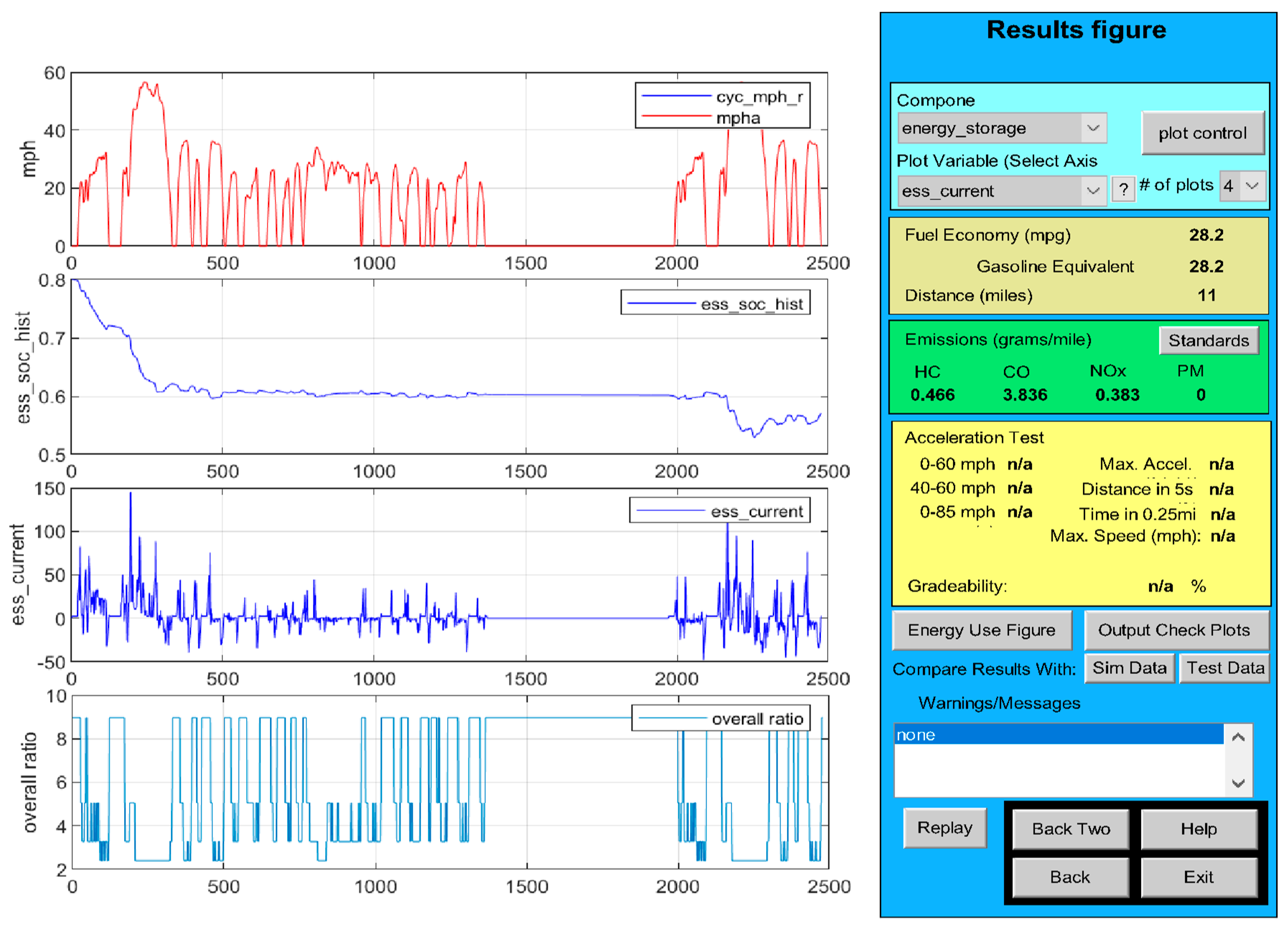
Furthermore, the SOC accuracy of the battery Li-ion Co model revealed by MATLAB simulation results are supported by the experimental results shown in Figure 28 for same FTP driving cycle test performed on the ADVISOR-MATLAB platform.
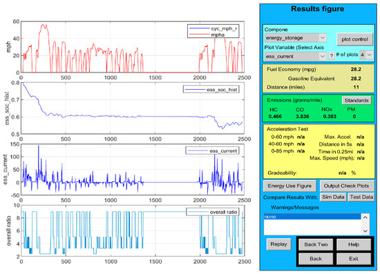
Figure 28.
FTP driving speed cycle of the input HEV midsize car; HEV car speed cycle; estimated Rint Li-ion battery SOC on NREL ADVISOR- MATLAB platform, and current profile (from the top to the bottom).
B. AEKF and LOE SOC estimators robustness
- R1-scenario
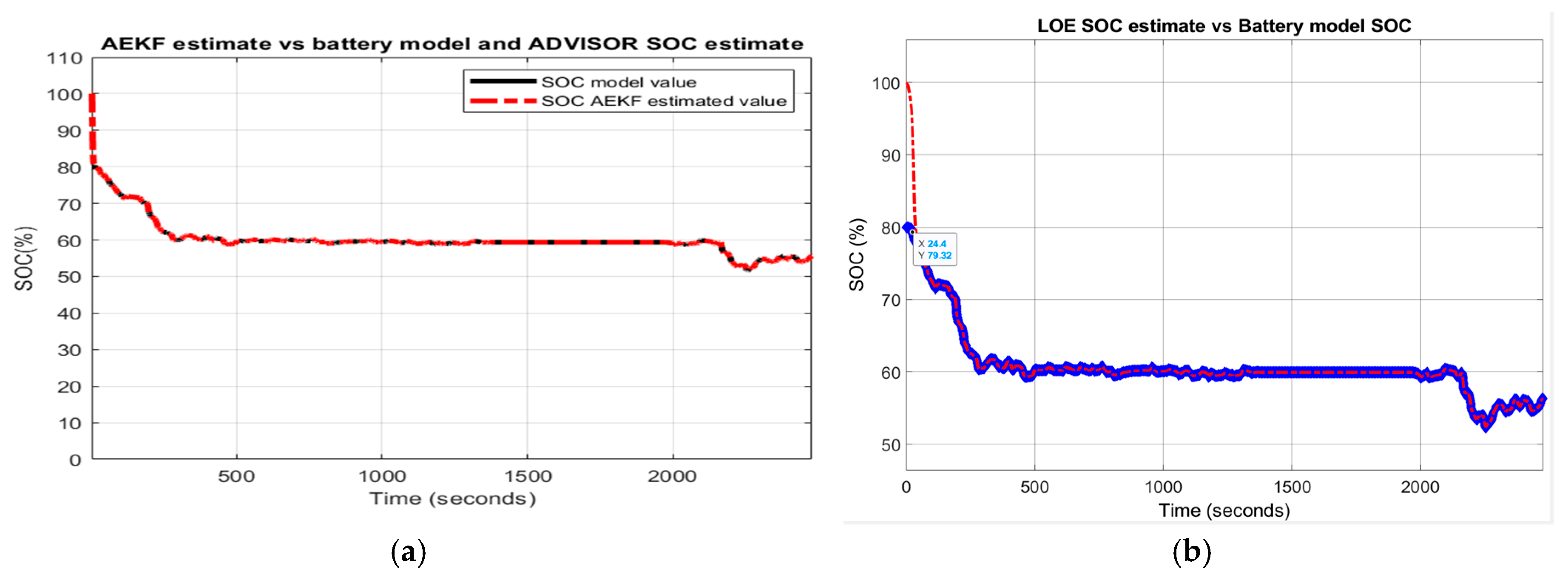
In Figure 29a,b are depicted the simulation results for both SOC estimators that reveal a great robustness performance for LOE SOC compared to AEKF SOC estimator.
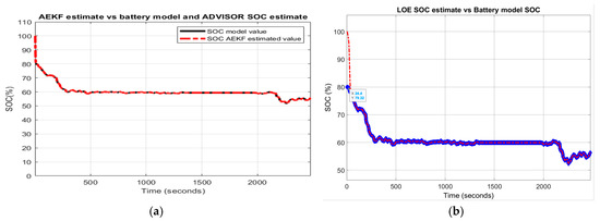
Figure 29.
Robustness performance of AEKF and LOE SOC estimators for R1-scenario; (a)AEKF SOC for R12; (b) LOE SOC for R12.
- R2-scenario
For this scenario, the simulation results shown in Figure 30a,b indicate a great robustness for AEKF SOC estimator compared to LOE SOC.
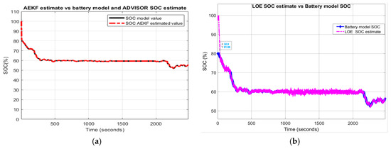
Figure 30.
AEKF and LOE SOC estimators - robustness performance for R2-scenario (a) AEKF SOC for R22; (b) LOE SOC for R22.
- R3-scenario
For the third scenario, the results presented in Figure A5a,b in Appendix A show a slight superiority of the LOE SOC estimator compared to the AEKF SOC estimator.
- R4-scenario
The output temperature profile of thermal model and the effects of temperature changes on the internal resistance Rint and polarization constant are shown in Figure A4a–c, and the results of MATLAB simulations are presented in Figure A6a,b (both figures in Appendix A). From Figure A6, it seems that the LOE SOC estimator performs better than AEKF SOC estimator. Also, the statistical errors for FTP ADVISOR driving cycle are summarized in Table A2 form Appendix A. As in the first two driving cycles, for the FTP driving cycle test the result of the robustness performance analysis based on the statistical errors included in Table A2 confirms again that the AEKF SOC estimator performs better than its competitor LOE SOC estimator. Thus, based on the statistical results of the three tables, it can now decide that the most appropriate SOC estimator for this type of HEV application is the AEKF SOC estimator which shows an absolute superiority compared to the LOE SOC estimator, due to its ability to filtrate the measurement noise, as well as more robust to the aging effects on the Li-ion Co battery.
4. Discussions
During this research, we have substantially enriched our experience in designing, modelling, implementing and validating Li-ion batteries, developing and implementing real-time SOC estimation algorithms in a friendly and attractive MATLAB-Simulink environment. Now we try to summarize some of the most relevant aspects that have captured our attention during this research.
4.1. SOC Estimators’ Convergence Speed
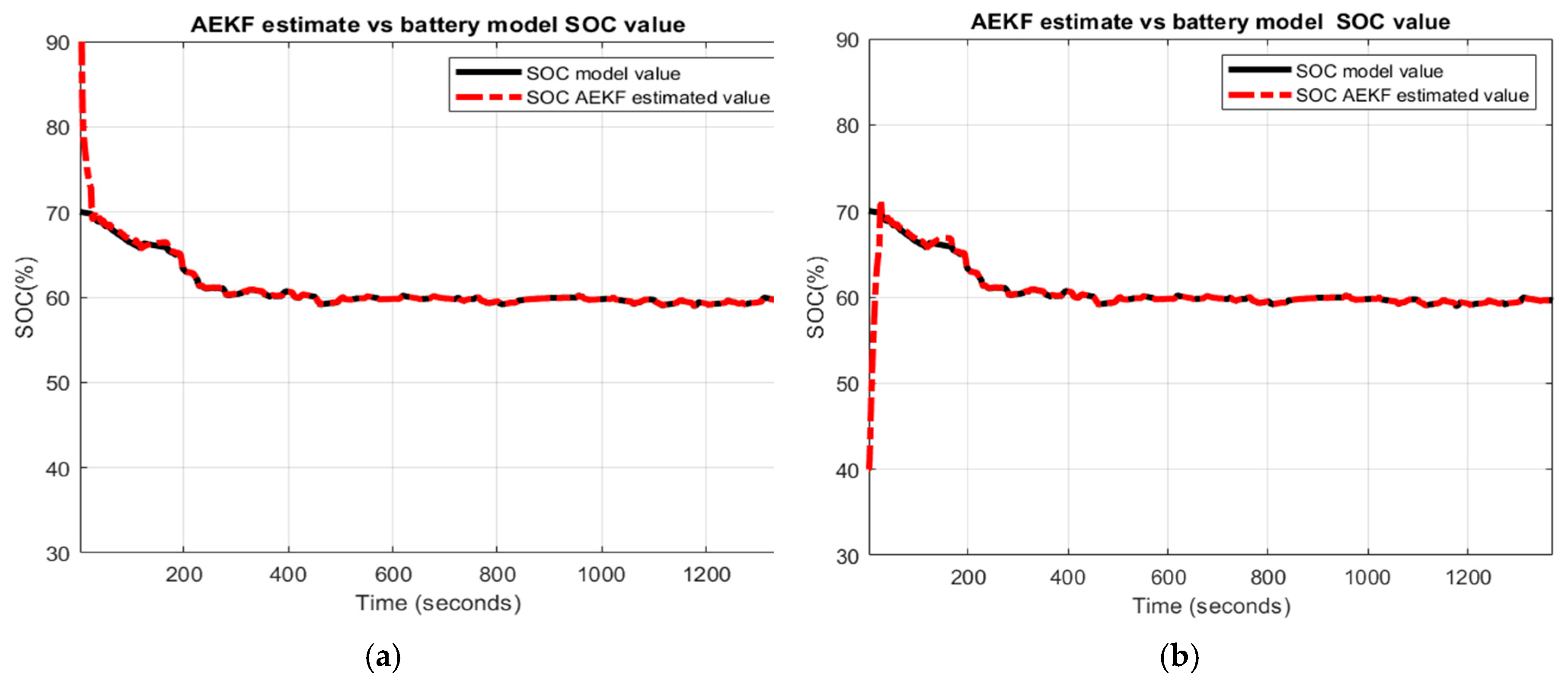
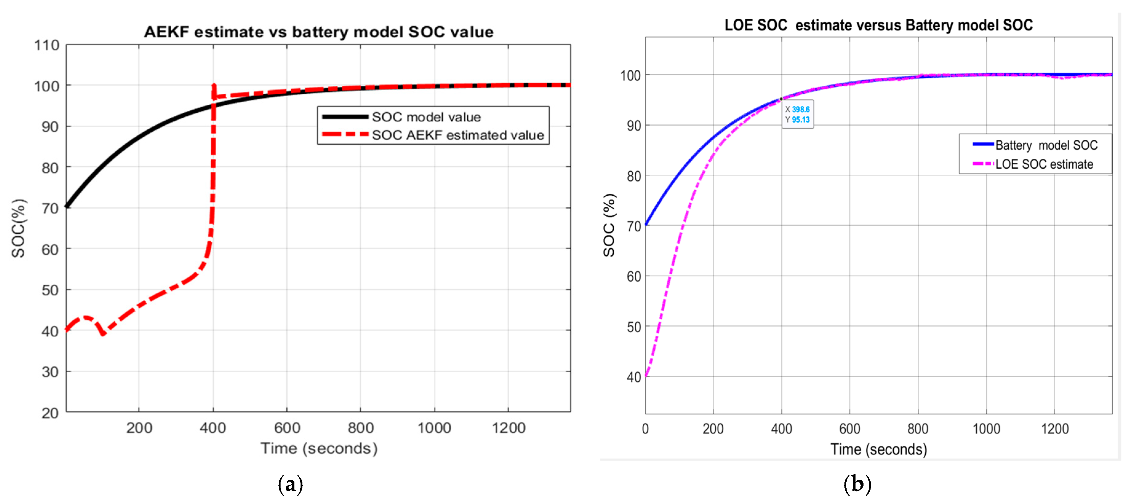
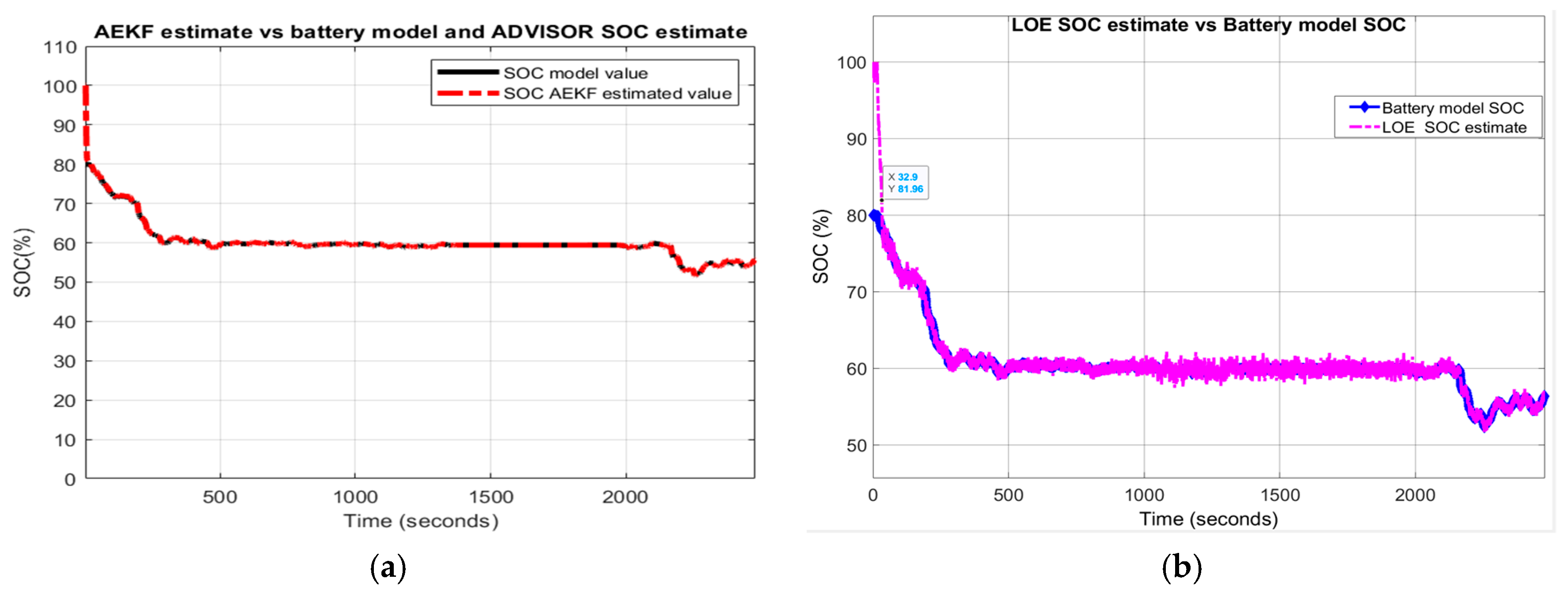
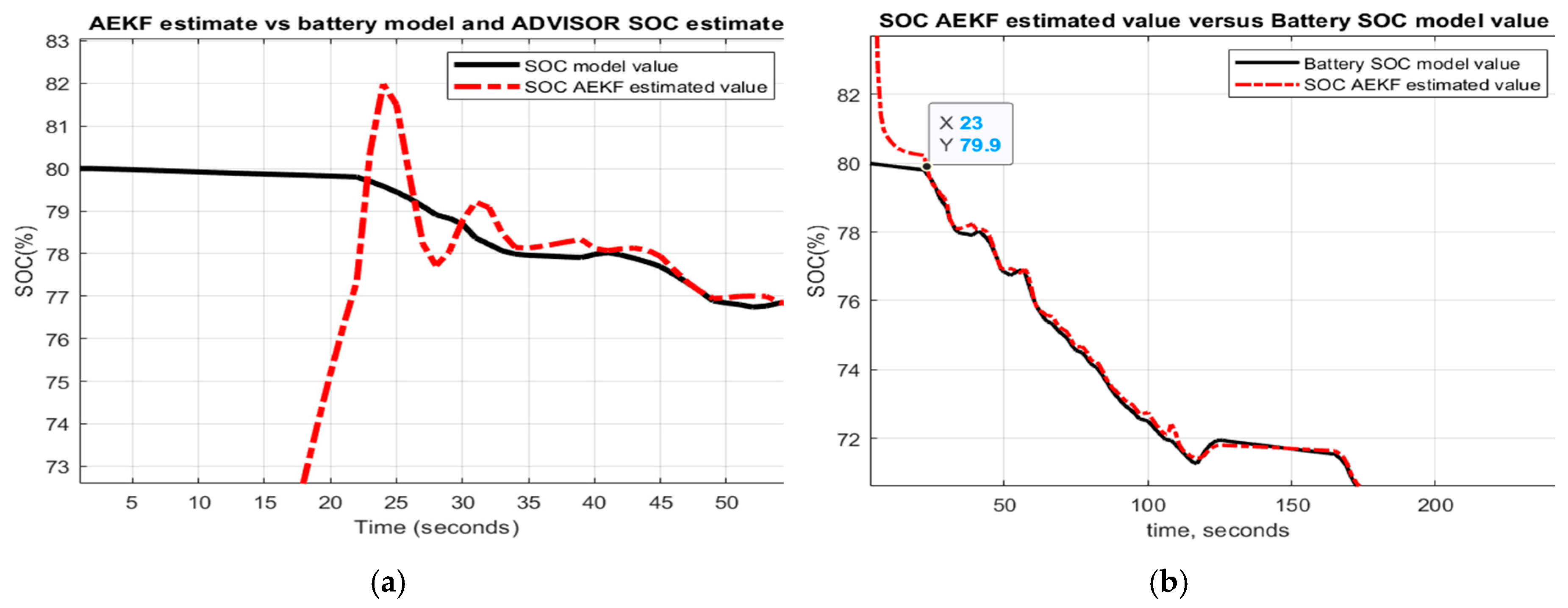
The analysis of the convergence speed performance of both SOC estimators can be done visually by examining the graphs strictly related to SOC. In almost all the graphs, the AEKF SOC estimate reaches the true value of Cobalt Li-ion battery model SOC after 40–190 s, when decreasing the SOC initial value from 80% to 40% or 16–150 s for an increase from 80% to 100%, as shown in Figure 31a,b by zooming at the beginning of the transient, which obviously is a rapid convergence speed.
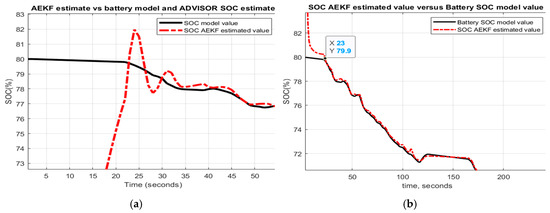
Figure 31.
AEKF SOC estimation convergence speed; (a) for a decrease SOC initial value; (b) for an increase initial value.
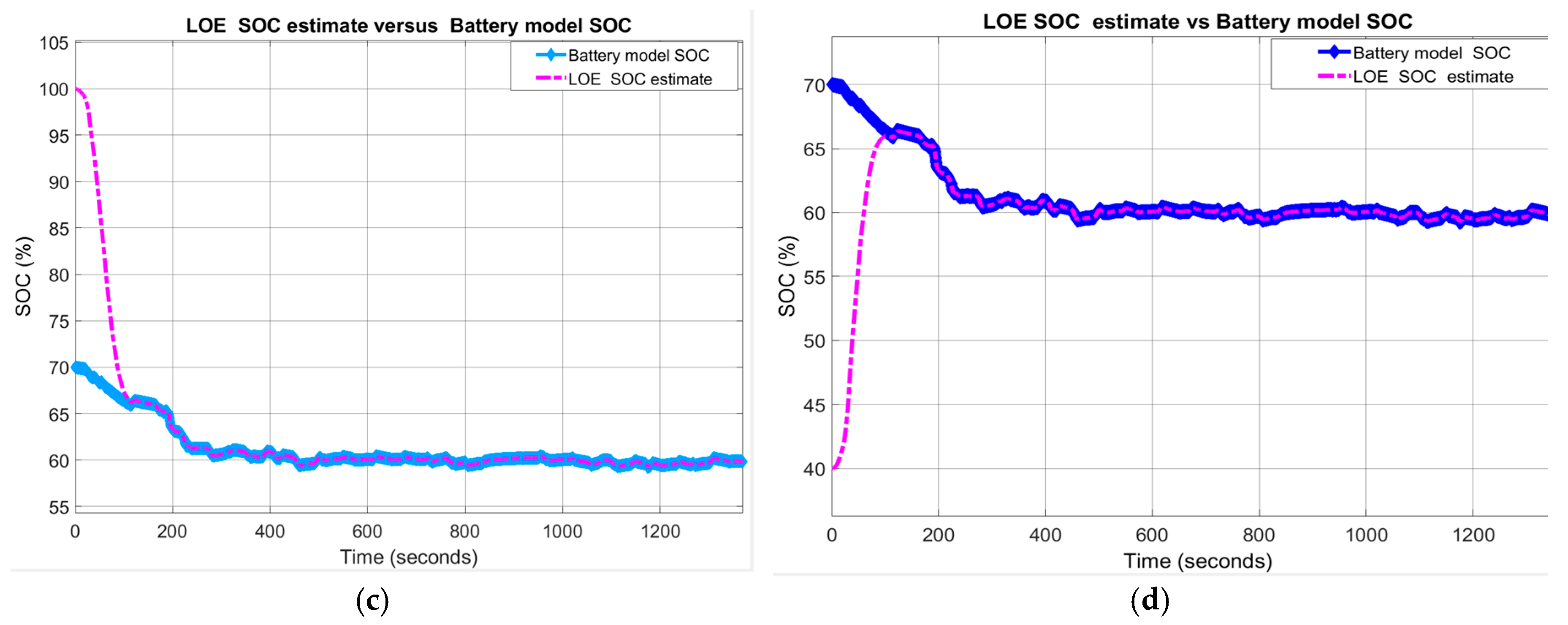
Compared to AEKF SOC estimator, the convergence speed of LOE SOC estimator can be controlled by choosing the most appropriate value for the observer gain. For high gain values, the LOE SOC estimator becomes much faster as can be seen for the FTP driving cycle test, where the observer gain is 100. For the UDDS driving cycle, the observer gain is 10 and, for performance analysis purpose, the observer gain for UDDS-EPA driving cycle is intentionally set to 1. For this case, the LOE SOC estimator reaches the true value of the battery model SOC after 400 s, much higher as compared to AEKF SOC estimator.
4.2. SOC Estimation Accuracy
The MATLAB simulation results shown in the previous section reveal, in most cases, an excellent SOC estimation accuracy of AEKF SOC estimator after the estimate reaches the battery model SOC true value. Still, in some cases, due to unsuitable values for the tuning parameters, the AEKF SOC estimate is biased compared to LOE SOC estimator. On the other hand, the LOE SOC estimator accumulates a significant estimation error during the transient. Regarding the EKF SOC estimator, we observed that the SOC accuracy depends on a “trial and error” empirical adjustment procedure of tuning parameter values. Unfortunately, this procedure takes a lot of time. Moreover, a new readjustment procedure is required when changing the driving conditions and SOC initial value, as well as when aging and temperature effects take place. The adopted version AEKF due to its adaptive features attenuates the tuning procedure of the parameters significantly.
4.3. SOC Estimator-Measurement Noise Filtration
An important aspect that we also observed in this research is the measurement noise filtration by both estimators. Only the AEKF has this ability to filtrate the measurement noise compared to LOE SOC estimator, as you can see, for example, in Figure 30b.
4.4. SOC Estimators-Real Time Implementation
As we mentioned in the previous section due to its “predictor-corrector structure”, the AEKF SOC estimator becomes a recursive algorithm, “more simple to implement in real time and computationally efficient” [10]. Also, the LOE SOC structure is simple and easy to design and implement in real time, in particular due to its linearized structure and having a single parameter needed for adjustment. In addition, the proposed generic lithium-ion cobalt battery model is simple, easy to design and quickly to implement in real time, based directly on the manufacturer’s battery specifications. MATLAB-Simulink software platform provides a valuable and practical Simscape SimPower Systems library, helpful to be used for designing and implementation of different HEVs and EVs powertrains configurations.
4.5. SOC Estimators-Statistical Errors Analysis
The results from the first line (RMSE, MSE, MAE) provide the accuracy of the battery model SOC and ADVISOR estimate, beneficial for Li-ion Co battery model validation performed in Section 2.6.4 for first UDDS driving cycle test and for third one FTP-75. The validation of the battery model for second UDDS-EPA driving cycle test is proved in Section 3.3 based on the MATLAB simulation results shown in Figure 22. The statistical errors from Table 3, Table A1 and Table A2 are valuable to compare the results of both SOC estimators to those obtained in the field literature by similar algorithms SOC estimators, for same driving cycle tests, and same performance error indicators (RMSE, MSE, MAE). In Section 2.5.2 the state of the art analysis focused on adaptive filters SOC estimators reported in the literature is made. For this analysis, Table 3, Table A1 and Table A2 provide valuable information to compare the results obtained by AEKF SOC estimator, in terms of accuracy and robustness performance, developed in actual research work to those obtained in [18,19,20,21,22,23,24] for similar conditions, especially for same input current cycle profiles. Unfortunately, it was possible to make only a partial analysis since many researchers use different input current profiles and different error indicators that do not match with those used in our research. But, for the cases that match with our current profile, the information collected in all three Table 3, Table A1 and Table A2 corresponding to each input current cycle profile can be useful to analyse all similar situations. Thus, the present research work can be a valuable source of inspiration for readers and researchers.
5. Conclusions
In this research paper, among the most relevant contributions the following may be highlighted:
- Model selection—MATLAB Simscape Li-ion cobalt nonlinear model, simple, practical, accurate, easy to implement in real-time (Section 2.6.1)
- Model development in continuous time state-space representation (Section 2.6.2)
- Model development in discrete time state-space representation (Section 2.6.3)
- Model validation based on three different driving cycles tests, using ADVISOR 3.2 software tool (Section 2.6.4)
- Model implementation in MATLAB R 2019b Simulink environment (Simulink diagram from Figure 8 and Figure 9, Section 2.6.4)
- Thermal model design and Simulink implementation (Simulink diagram from Figure 12 Section 2.7)
- Adaptive Extended Kalman Filter SOC estimator with fading feature—Design and MATLAB implementation, Section 3.1)
- Linear observer SOC estimator-Design and Simulink implementation (Simulink model diagram from Figure 16, Section 3.2)
- MATLAB SOC simulations (Section 3.3)
The case study is a 5.4 Ah Li-ion Cobalt battery, of high simplicity and accuracy, easy to be implemented in real-time and to provide beneficial support to build two real-time AEKF and LOE SOC estimators. For a good insight on the realistic battery life environment, the case of the battery internal resistance and polarization coefficient as parameters temperature-dependent is also investigated. Both parameters are updated dynamically through a simplified thermal model designed in Section 2.7. The robustness and accuracy of both SOC estimators is investigated in detail, for three most used driving cycles tests in the automotive industry (UDDS, UDDS-EPA and FTP) and changes in:
- ○
- SOC initial value (“guess” value)
- ○
- SOC initial value and driving conditions
- ○
- SOC initial value, temperature effects on internal resistance and polarization constant, and driving conditions.
- ○
- SOC initial value, nominal value of battery capacity due to aging effects/temperature effects and driving conditions.
Based on the statistical errors calculated for each driving cycle test in terms of RMSE, MSE and MAE, it was possible to choose from both competitors the most suitable SOC estimator. The result of overall performance analysis indicates that the AEKF SOC estimator performs better than LOE SOC estimator.
In the future work, we continue our investigations on lithium batteries regarding an improved modelling approach by “integrating the effect of degradation, temperature and SOC effects” [10], and for possible extensions to more accurate adaptive neural fuzzy logic SOC estimation techniques.
Author Contributions
R.-E.T. has contributed for algorithms conceptualization, manuscript preparation and writing it. N.T. has contributed for battery model validation, performed the MATLAB simulations and analyzed the results. M.Z. has contributed for a formal analysis of the results, for the visualization, the project supervision and administration. All authors have read and agreed to the published version of the manuscript.
Funding
This research received no external funding.
Acknowledgments
Research funding (discovery grant) for this project from the Natural Sciences and Engineering Research Council of Canada (NSERC) is gratefully acknowledged.
Conflicts of Interest
The authors declare no conflict of interest.
Abbreviations
| Ni-Cad | nickel cadmium |
| Ni-MH | nickel metal hydride |
| Li-ion Co | lithium-ion cobalt |
| EV | electric vehicle |
| HEV | hybrid electric vehicle |
| BMS | battery management system |
| ADVISOR | advanced vehicle simulator |
| EPA | environmental protection agency |
| UDDS | urban dynamometer driving schedule |
| FTP-75 | Federal test procedure at 75 F |
| SMO | sliding mode observer |
| LOE | linear observer estimator |
| RMSE | root mean squared error |
| MSE | mean squared error |
| MAE | mean absolute error |
| OCV | open-circuit voltage |
| SOC | state of charge |
| SOE | state of energy |
| SOH | state of health |
| DOD | depth of discharge |
| NREL | National Renewable Energy Laboratory |
| UKF | unscented Kalman filter |
| AUKF | adaptive unscented Kalman filter |
Appendix A
Appendix A.1. Figures
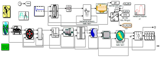
Figure A1.
The Simulink block diagram of a hypothetical midsize town car-the diagram includes the following blocks: differential, clutch, gear, battery system, transmission and accessories
Figure A1.
The Simulink block diagram of a hypothetical midsize town car-the diagram includes the following blocks: differential, clutch, gear, battery system, transmission and accessories
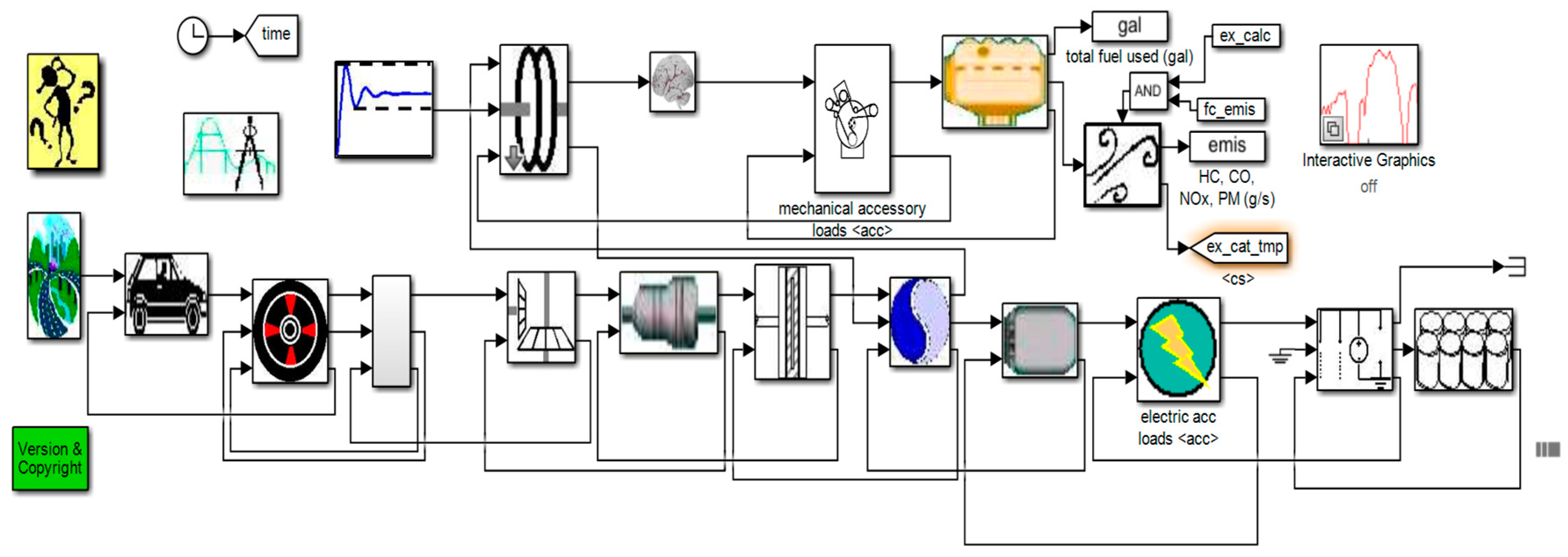
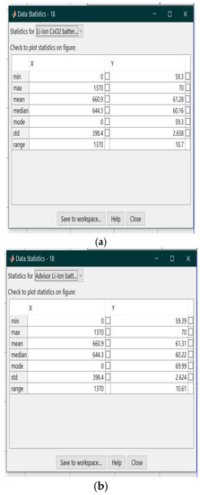
Figure A2.
The UDDS test on the ADVISOR 3.2 integrated MATLAB platform; (a) The plot of statistic errors for Li-Ion CO2 battery model, (b)The plot of the statistic errors for Advisor Li battery Rint model.
Figure A2.
The UDDS test on the ADVISOR 3.2 integrated MATLAB platform; (a) The plot of statistic errors for Li-Ion CO2 battery model, (b)The plot of the statistic errors for Advisor Li battery Rint model.
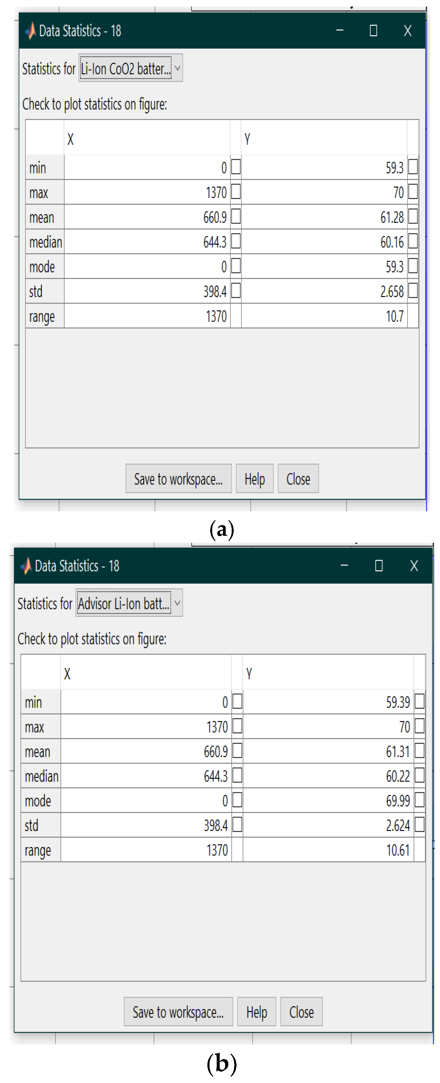
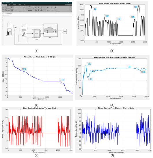
Figure A3.
(a) Electric Vehicle simulation model application. (b) motor speed in RPM; (c) battery SOC (%); (d), US fuel economy; (e) motor torque (Nm); (f) discharge battery current profile.
Figure A3.
(a) Electric Vehicle simulation model application. (b) motor speed in RPM; (c) battery SOC (%); (d), US fuel economy; (e) motor torque (Nm); (f) discharge battery current profile.
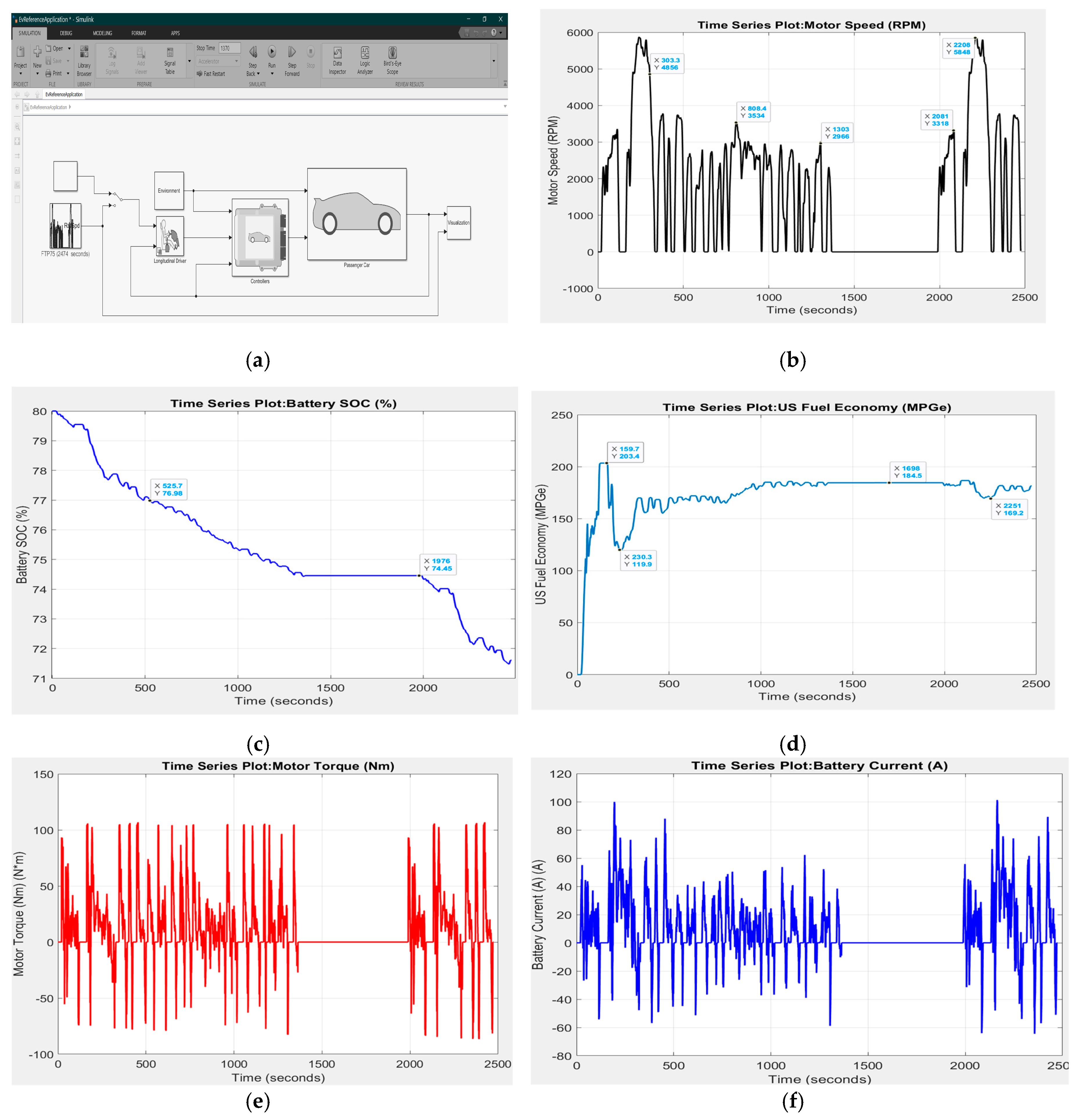
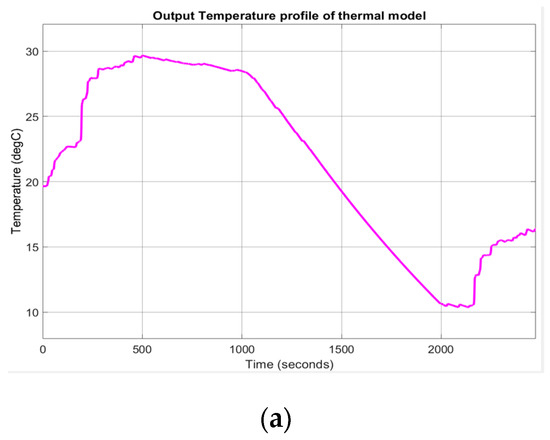
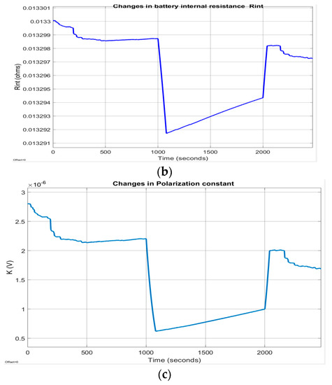
Figure A4.
Temperature effects on Rint and K. (a) output temperature profile; (b) internal battery resistance Rint; (c) polarization constant K.
Figure A4.
Temperature effects on Rint and K. (a) output temperature profile; (b) internal battery resistance Rint; (c) polarization constant K.
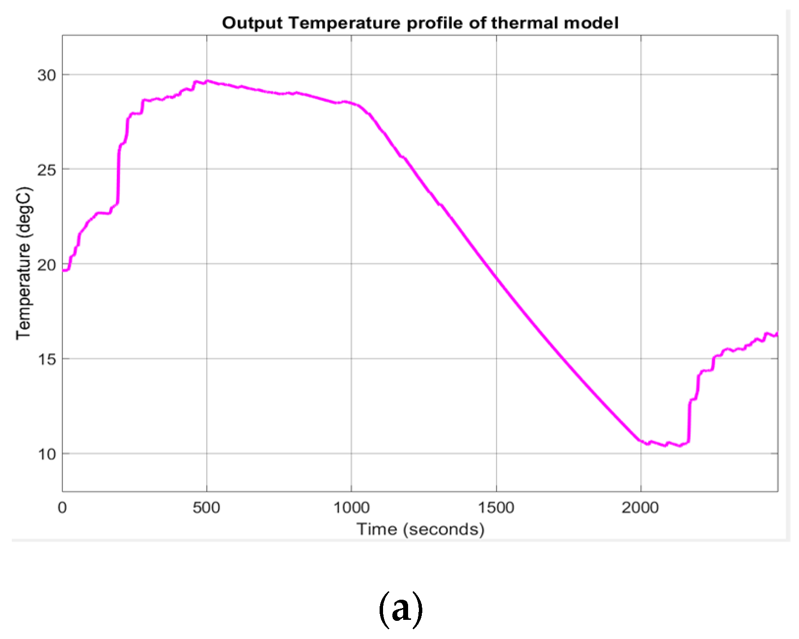
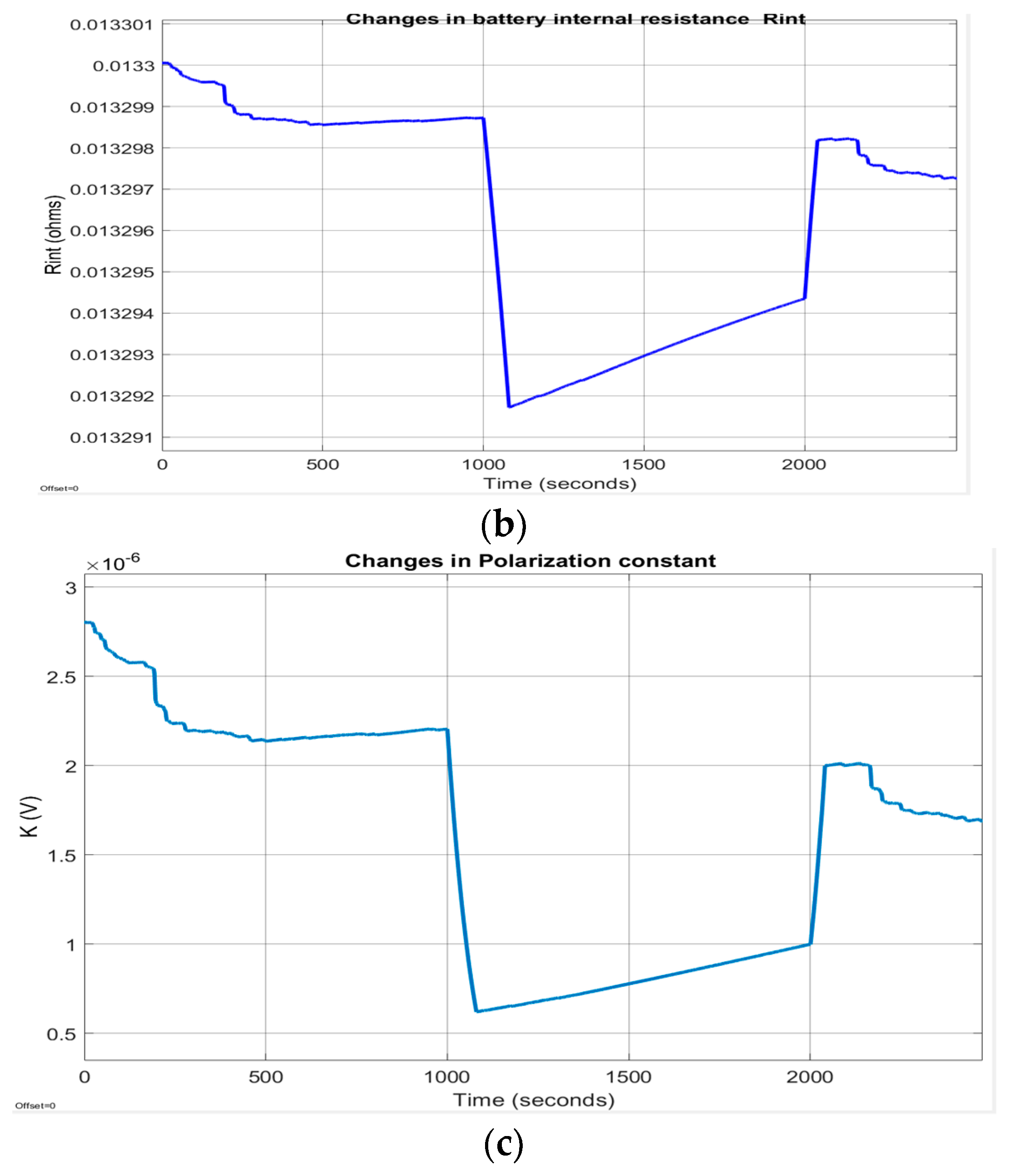
Figure A5.
Robustness performance of AEKF and LOE SOC estimators for R3-scenario; (a) AEKF SOC for R32; (b) LOE SOC for R32.
Figure A5.
Robustness performance of AEKF and LOE SOC estimators for R3-scenario; (a) AEKF SOC for R32; (b) LOE SOC for R32.
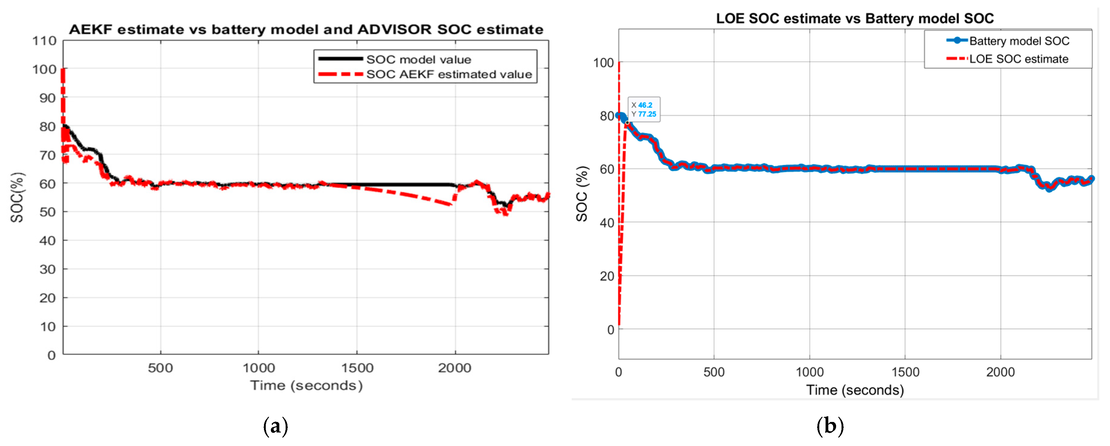
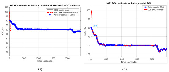
Figure A6.
Robustness of AEKF and LOE SOC estimators for R4-scenario; (a) AEKF SOC for R42; (b) LOE SOC for R42.
Figure A6.
Robustness of AEKF and LOE SOC estimators for R4-scenario; (a) AEKF SOC for R42; (b) LOE SOC for R42.
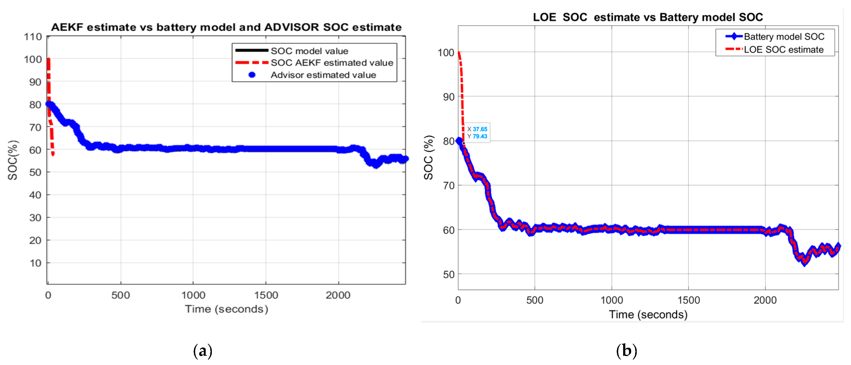
Appendix A.2. Tables

Table A1.
AEKF SOC Estimator—statistic errors.
Table A1.
AEKF SOC Estimator—statistic errors.
| Cycle Test | Accuracy | SOCest Initial Value (%) | Statistic Errors | |||||||
|---|---|---|---|---|---|---|---|---|---|---|
| RMSE AEKF | RMSE LOE | MSE AEKF | MSE LOE | MAE AEKF | MAE LOE | Std AEKF (%) | Std LOE (%) | |||
| UDDS-EPA | Battery model vs. ADVISOR | 70 | 0.2621 | 0.2630 | 0.0173 | 0.0180 | 0.0224 | 0.0285 | 7.22 | 4.29 |
| AEKF/LOE | 70 | 0.0325 | 0.0898 | 0.0000036 | 0.0004 | 0.0018 | 0.000459 | 2.6 | 7.35 | |
| R1-scenario | R12 | 0.2290 | 0.2031 | 0.0212 | 0.4126 | 0.0726 | 0.1896 | 18.8 | 11.14 | |
| R2-scenario | R22 | 0.2289 | 0.2013 | 0.2123 | 0.0405 | 0.0786 | 0.1879 | 18.8 | 11 | |
| R3-scenario | R32 | 0.2290 | 0.2311 | 0.0212 | 0.0534 | 0.0786 | 0.2251 | 18.87 | 7.4 | |
| R4-scenario | R42 | 0.2341 | 0.2041 | 0.0130 | 0.0416 | 0.0792 | 0.1913 | 19.55 | 11 | |

Table A2.
AEKF and LOE SOC Estimators—statistical errors.
Table A2.
AEKF and LOE SOC Estimators—statistical errors.
| Cycle Test | Accuracy | SOCest Initial Value (%) | Statistic Errors | |||||||
|---|---|---|---|---|---|---|---|---|---|---|
| RMSE AEKF | RMSE LOE | MSE AEKF | MSE LOE | MAE AEKF | MAE LOE | Std AEKF (%) | Std LOE (%) | |||
| FTP | Battery model vs. ADVISOR | 70 | 0.0819 | 0.0834 | 0.0028 | 0.0043 | 0.0264 | 0.0235 | 4 | 4.29 |
| AEKF/LOE | 70 | 0.0011 | 0.00063 | 0.00312 | 0.00006 | 0.008627 | 0.00067 | 4.3 | 2.82 | |
| R1-scenario | R12 | 0.2392 | 0.0.0913 | 0.4280 | 0.0083 | 0.0082 | 0.0488 | 4.1 | 10 | |
| R2-scenario | R22 | 0.0753 | 0.1004 | 0.00037 | 0.01 | 0.00169 | 0.0633 | 4.34 | 10.47 | |
| R3-scenario | R32 | 0.0793 | 0.2651 | 0.0006 | 0.0703 | 0.0220 | 0.1297 | 4.27 | 21.3 | |
| R4-scenario | R42 | 0.0683 | 0.0913 | 0.000198 | 0.0083 | 0.0071 | 0.0488 | 5.39 | 10.17 | |
References
- Moshirvaziri, A. Lithium-Ion Battery Modelling for Electric Vehicles and Regenerative Cell Testing Platform. Master’s Thesis, University of Toronto, Toronto, ON, Canada, 2013. [Google Scholar]
- Electric Vehicle Integration into Modern Power Networks; Springer Science and Business Media LLC: Berlin, Germany, 2013; pp. 15–26.
- Xia, B.; Zheng, W.; Zhang, R.; Lao, Z.; Sun, Z. A Novel Observer for Lithium-Ion Battery State of Charge Estimation in Electric Vehicles Based on a Second-Order Equivalent Circuit Model. Energies 2017, 10, 1150. [Google Scholar] [CrossRef]
- Farag, M. Lithium-Ion Batteries, Modeling and State of Charge Estimation. Master’s Thesis, McMaster University of Hamilton, Hamilton, ON, Canada, 2013. [Google Scholar]
- Cui, X.; Shen, W.; Zhang, Y.; Cungang, H. A Novel Active Online State of Charge Based Balancing Approach for Lithium-Ion Battery Packs during Fast Charging Process in Electric Vehicles. Energies 2017, 10, 1766. [Google Scholar] [CrossRef]
- Lowe, M.; Tokuoka, S.; Trigg, T.; Gereffi, G. Li-Ion Batteries for Electric Vehicles. The US Chain. Research Report. Center on Globalization Governance and Competitiveness, 5 October 2010; pp. 1–68. Available online: https://unstats.un.org/unsd/trade/s_geneva2011/refdocs/RDs/Lithium-Ion%20Batteries%20(Gereffi%20-%20May%202010).pdf (accessed on 2 March 2018).
- Plett, G.L. Extended Kalman filtering for battery management systems of LiPB-based HEV battery packs: Part 1. Background. J. Power Sources 2004, 134, 252–261. [Google Scholar] [CrossRef]
- Plett, G.L. Extended Kalman filtering for battery management systems of LiPB-based HEV battery packs: Part 2. Modeling and identification. J. Power Sources 2004, 134, 262–276. [Google Scholar] [CrossRef]
- Plett, G.L. Extended Kalman filtering for battery management systems of LiPB-based HEV battery packs: Part 3. State and parameter estimation. J. Power Sources 2004, 134, 277–292. [Google Scholar] [CrossRef]
- Tudoroiu, R.-E.; Zaheeruddin, M.; Radu, S.M.; Tudoroiu, R.-E. Real-Time Implementation of an Extended Kalman Filter and a PI Observer for State Estimation of Rechargeable Li-Ion Batteries in Hybrid Electric Vehicle Applications—A Case Study. Batteries 2018, 4, 19. [Google Scholar] [CrossRef]
- Tudoroiu, R.-E.; Zaheeruddin, M.; Radu, S.M.; Tudoroiu, N. New Trends in Electrical Vehicle Powertrains. New Trends Electr. Veh. Powertrains 2019, 4. [Google Scholar] [CrossRef]
- Tudoroiu, N.; Radu, S.M.; Tudoroiu, R.-E. Improving Nonlinear State Estimation Techniques by Hybrid. Structures, 1st ed.; LAMBERT Academic Publishing: Saarbrucken, Germany, 2017; p. 56. ISBN 978-3-330-04418-0. [Google Scholar]
- Gonzalez, C. The Future of Electric Hybrid Aviation, Machine Design, Technologies-Batteries/Power Supplies, March 2016. Available online: http://www.machinedesign.com/batteriespower-supplies/future-electric-hybrid-aviation (accessed on 24 March 2018).
- Simon, J.J.; Uhlmann, J.K. A New Extension of the Kalman Filter to Nonlinear Systems. In Proceedings of the SPIE 3068, Signal Processing, Sensor Fusion, and Target Recognition VI, Orlando, FL, USA, 28 July 1997; p. 3068. Available online: https://people.eecs.berkeley.edu/~pabbeel/cs287-fa09/readings/JulierUhlmann-UKF.pdf (accessed on 21 January 2018). [CrossRef]
- Xu, J.; Cao, B. Battery Management System for Electric Drive Vehicles – Modeling, State Estimation and Balancing. In New Applications of Electric Drives; IntechOpen: London, UK, 2015; pp. 87–113. [Google Scholar]
- Javier Muñoz Alvarez, J.M.; Sachenbacher, M.; Ostermeier, D.; Stadlbauer, H.J.; Hummitzsch, U.; Alexeev, A. Analysis of the State of the Art on BMS; Everlasting D6.1 Report; Lion Smart GmbH: Munchen, Germany, 2017. [Google Scholar]
- Zhang, R.; Xia, B.; Li, B.; Cao, L.; Lai, Y.; Zheng, W.; Wang, H.; Wang, W. State of the Art of Lithium-Ion Battery SOC Estimation for Electrical Vehicles. Energies 2018, 11, 1820. [Google Scholar] [CrossRef]
- Chang, W.-Y. The State of Charge Estimating Methods for Battery: A Review. ISRN Appl. Math. 2013, 2013, 1–7. [Google Scholar] [CrossRef]
- Lee, S.J.; Kim, J.H.; Lee, J.M.; Cho, B.H. The state and parameter estimation of an Li-Ion battery using a new OCV-SOC concept. In Proceedings of the 2007 Power Electronics Specialists conference, Orlando, FL, USA, 17–21 June 2007; pp. 2799–2803. [Google Scholar]
- Chen, Z.; Fu, Y.; Mi, C.C. State of Charge Estimation of Lithium-Ion Batteries in Electric Drive Vehicles Using Extended Kalman Filtering. IEEE Trans. Veh. Technol. 2012, 62, 1020–1030. [Google Scholar] [CrossRef]
- He, H.; Liu, Z.; Hua, Y. Adaptive Extended Kalman Filter Based Fault Detection and Isolation for a Lithium-Ion Battery Pack. Energy Procedia 2015, 75, 1950–1955. [Google Scholar] [CrossRef]
- Diab, Y.; Auger, F.; Schaeffer, E.; Wahbeh, M. Estimating Lithium-Ion Battery State of Charge and Parameters Using a Continuous-Discrete Extended Kalman Filter. Energies 2017, 10, 1075. [Google Scholar] [CrossRef]
- Zhao, Y.; Xu, J.; Wang, X.; Mei, X. The Adaptive Fading Extended Kalman Filter SOC Estimation Method for Lithium-ion Batteries. Energy Procedia 2018, 145, 357–362. [Google Scholar] [CrossRef]
- Wang, D.; Bao, Y.; Shi, J. Online Lithium-Ion Battery Internal Resistance Measurement Application in State-of-Charge Estimation Using the Extended Kalman Filter. Energies 2017, 10, 1284. [Google Scholar] [CrossRef]
- Tremblay, O.; Dessaint, L.-A.; Dekkiche, A.-I. A Generic Battery Model. for the Dynamic Simulation of Hybrid. Electric Vehicles; Institute of Electrical and Electronics Engineers (IEEE): New York, NY, USA, 2007; pp. 284–289. [Google Scholar]
- Zhang, Y.; Xiong, R.; He, H.; Shen, W. Lithium-Ion Battery Pack State of Charge and State of Energy Estimation Algorithms Using a Hardware-in-the-Loop Validation. IEEE Trans. Power Electron. 2017, 32, 4421–4431. [Google Scholar] [CrossRef]
- Syed Mahdi, A. Battery Identification, Prediction and Modelling. Master’s Thesis, Colorado State University Fort Collins, Fort Collins, CO, USA, 2018. [Google Scholar]
- DiOrio, N.; Dobos, A.; Janzou, S.; Nelson, A.; Lundstrom, B. Technoeconomic Modeling of Battery Energy Storage in SAM; US NREL Technical Report; NREL/TP-6A20-64641. Contract No. DE-AC36-08GO28308; NREL: Denver, CO, USA, 2015. Available online: https://www.nrel.gov/docs/fy15osti/64641.pdf (accessed on 3 March 2020).
- Song, D.; Sun, C.; Wang, Q.; Jang, D. A Generic Battery Model and Its Parameter Identification. Energy Power Eng. 2018, 10, 10–27. [Google Scholar] [CrossRef]
- Johnson, V. Battery performance models in ADVISOR. J. Power Sources 2002, 110, 321–329. [Google Scholar] [CrossRef]
- Wipke, K.B.; Cuddy, R.M. Using an Advanced Vehicle Simulator (ADVISOR) to Guide Hybrid Vehicle Propulsion System Development. Publisher: Golden, CO: National Renewable Energy Laboratory. August 1996. Research gate net. Available online: https://www.nrel.gov/docs/legosti/fy96/21615.pdf (accessed on 1 March 2020).
- Xing, Y.; Ma, E.W.M.; Tsui, K.-L.; Pecht, M.G. Battery Management Systems in Electric and Hybrid Vehicles. Energies 2011, 4, 1840–1857. [Google Scholar] [CrossRef]
- Jiang, J.; Zhang, C. Fundamentals and Applications of Lithium-ion Batteries in Electric Drive Vehicles; Wiley: Singapore, 2015; p. 300. [Google Scholar]
- Lakkis, M.E.; Sename, O.; Corno, M.; Bresch, P.D. Combined battery SOC/SOH estimation using a nonlinear adaptive observer. European Control Conference 2015, Linz, Austria. In Proceedings of the European Control Conference, Linz, Austria, 15–17 July 2015. [Google Scholar] [CrossRef]
- Battery and Engineering Technologies. Battery Life and Death. Available online: http://www.mpoweruk.com/life.htm (accessed on 18 March 2018).
- Taesic, K. A Hybrid Battery Model Capable of Capturing Dynamic Circuit Characteristics and Nonlinear Capacity Effects. Master’s Thesis, University of Nebraska, Lincoln, NE, USA, July 2012. [Google Scholar]
- Siva, R.; Prasanna, M. Modeling, Simulation & Implementation of Li-Ion Battery Powered Electric and Plug-in Hybrid Vehicles. Master’s Thesis, University of Akron, Akron, OH, USA, August 2011. [Google Scholar]
© 2020 by the authors. Licensee MDPI, Basel, Switzerland. This article is an open access article distributed under the terms and conditions of the Creative Commons Attribution (CC BY) license (http://creativecommons.org/licenses/by/4.0/).

