Article

Heating Performance Characteristics of an Electric Vehicle Heat Pump Air Conditioning System Based on Exergy Analysis

1
State Key Laboratory of Automotive Simulation and Control, Jilin University, Changchun 130025, China
2
College of Automotive Engineering, Jilin University, Changchun 130025, China
3
College of Computer Science and Technology, Jilin University, Changchun 130025, China
4
FAWER Hanon Thermal Systems (Changchun) Company Ltd., Changchun 130011, China
*
Author to whom correspondence should be addressed.
Energies 2020, 13(11), 2868; https://doi.org/10.3390/en13112868
Submission received: 8 May 2020 / Revised: 31 May 2020 / Accepted: 3 June 2020 / Published: 4 June 2020
(This article belongs to the Special Issue Exergy Analysis and Optimization of Energy Systems and Processes)

Abstract

:
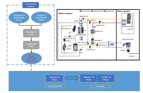
In this paper, a heat pump air conditioning system (HPACS) with refrigerant R134a based on the functional requirements of battery electric vehicle is designed and tested. Experiments were conducted to evaluate the effects of different ambient temperature, air flow rate of internal condenser, expansion valve (EXV) opening and compressor speed. The results demonstrate that air flow rate of internal condenser, EXV opening and compressor speed have important impact on heating capacity, compressor power consumption and coefficient of performance (COP) under several ambient temperatures. To verify the HPACS can also provide the heating capacity required by the battery electric vehicle cabin in cold climate, the system was also tested under a −5 °C ambient temperature, it was found that the heating capacity is 3.6 kW and the COP is 3.2, demonstrating that the system has high energy efficiency. In addition, heating process analysis of the HPACS under lower temperature is studied by exergy principle. The results indicate that compressor is the highest exergy destruction in all components, accounting for 55%. The percentage of exergy destruction in other components is about 28%, 12% and 5% for the expansive valve, condenser, and evaporator. Furthermore, air flow rate of internal condenser, ambient temperature and expansion valve opening have important impact on exergy destruction and exergy efficiency of the HPACS.

Graphical Abstract

1. Introduction

With the development of social economy and improvement of environmental requirements, battery electric vehicles (BEV) are considered as a potential substitute for conventional internal combustion engine automobile [1,2]. Unlike traditional vehicles, there is no enough waste heat from power system to be utilized to warm up the cabin of BEV [3]. Besides, because the battery is the only energy source of BEV, the air conditioning system will reduce the driving mileage of electric vehicle and affect the power performance of the whole vehicle in the winter [4]. In order to adapt these changes, an additional heater is required for cabin heating in the winter. HPACS is a kind of heating device with high efficiency, so the application of HPACS is an irresistible trend for electric vehicle in cold area in the future [5,6,7]. Under the condition of providing the same heating capacity, the electric energy consumed by the HPACS is significantly lower than that of positive temperature coefficient (PTC)heater. The HPACS will greatly reduce the electric vehicle energy consumption.
Although the heating efficiency of the HPACS is higher, its application in electric vehicles is rare at present, and the main technical problems faced are as follows: firstly, the coefficient of performance (COP) of the HPACS is obviously affected by the ambient temperature, when the ambient temperature decreases, the COP will decrease significantly [8]. Secondly, when the HPACS operates in low temperature and high humidity, the external heat exchanger of the HPACS is prone to frost in heating mode and it will cause both blockage of the air channels and increase the overall thermal resistance of the exterior heat exchanger [9,10,11]. Thirdly, when the ambient temperature is lower than −15 °C, the HPACS with refrigerant R134a cannot provide enough heating energy to the cabin [12]. Kim et al. tested heating performances of the HPACS under a wide range of ambient temperature. When the ambient temperature was at 10 °C, the heating capacity and COP were 2.8 kW and 1.76, respectively, while, at −15 °C the heating capacity and COP dropped dramatically to 1.4 kW and 1.29, respectively [13]. Hosoz and Direk investigated the operating characteristics of an air-source heat pump with refrigerant R134a. The system provided sufficient heating performance in mild weather conditions, but its heating capacity dropped rapidly with the decreasing of the outdoor temperature, necessitating the use of a supplemental heating device for proper heating operation [14]. Therefore, it is vital to solve these problems, so as to improve working performance and reliability of HPACS in heating mode for BEV.
In order to make the temperature meet the specific needs, some scholars have conducted research and analysis on types of heat pumps and thermoacoustic refrigerators [15,16,17]. For the HPACS of BEV, Wanyong Li et al. evaluated performances of HPACS with R1234yf refrigerant. The results indicated that the heating performance of with R1234yf refrigerant are very similar to R134a [18]. Jing Wu et al. conducted a comprehensive assessment of refrigerants for cabin heating and cooling on electric vehicles. The results showed that the R290 refrigerant generates the lowest amount of equivalent CO2 emission whereas R744 gives off the highest amount. With a low GWP value and very high heating capacity, R32 is a promising refrigerant for the HPACS in the future [19]. Xu Peng et al. conducted a numerical investigation on the heating performance of the HPACS with CO2 refrigerant. The results showed that the transcritical CO2 vapor-injection heat pump is better than a transcritical CO2 single-stage heat pump system [20].
Exergy is the property defined to describe the energy quality, which represents the maximum theoretical limit that can be converted into useful work in a certain form of energy under certain environmental conditions. For exergy analysis, it can analyze the components of the system separately to identify the main sites and sources of exergy destruction based on both the first and second law of thermodynamics. Dandong Wang et al. analyzed the heating capacity, exergy loss and exergy efficiency of a HPACS with CO2 refrigerant for different ambient temperature. The results showed that the gas cooler has the highest exergy destruction, which takes more than 30% of that of all components. Additionally, ambient temperature has little effect on exergy efficiency [21]. Di Wu et al. studied the system performance of HPACS with R1234ze(Z) refrigerant and a hybrid source HPACS with CO2 and R1234ze(Z) refrigerant based on exergy analysis. The results indicated that the exergy efficiency gradually increased along with the increment of subcooling of R1234ze(Z) in IHE. When the condensing temperature is 10 °C, the exergy efficiency of the hybrid source heat pump system is improved by 27.2% more than HPACS with R1234ze(Z) [22]. Sahar Taslimi et al. evaluate the system performance of a CO2 two-phase ejector for the HPACS based on Grassmann exergy analysis and transiting exergy analysis. It was concluded that transiting exergy analysis is more suitable for a CO2 two-phase ejector compared to Grassmann exergy analysis [23]. Honghyun Cho et al. conducted an advanced exergy analysis on automotive air conditioning systems with R1234yf refrigerant. The results indicated that for the R1234yf system with an internal heat exchanger (IHX), the IHX can improve cooling capacity, thus increasing the system exergy efficiency compared to without the IHX [24]. Jianyong Chen et al. was the first to apply the advanced exergy analysis to ejector refrigeration systems and the system performance can be largely enhanced based this method [25,26].
Some of the above papers have only focused on the heating performance from perspective of the types of the heat pumps. Or others have been paid little attention to the impact of the system performance from the “quality” of energy. The main purpose of this paper is to study the influence of the electrical expansion valve (EXV), air flow rate of the internal heat exchanger, compressor speeds and ambient temperature on heating performance of the HPACS for BEV in a cold area and exergy destruction in depth. Thereby, getting the optimization direction of component of HPACS and enhance the heating performance of HPACS. The ultimate goal is to improve the thermal management performance of BEV and promote the further development of BEV with high efficiency, low energy consumption.

2. Experimental Setup and Test Method

2.1. Experimental Setup

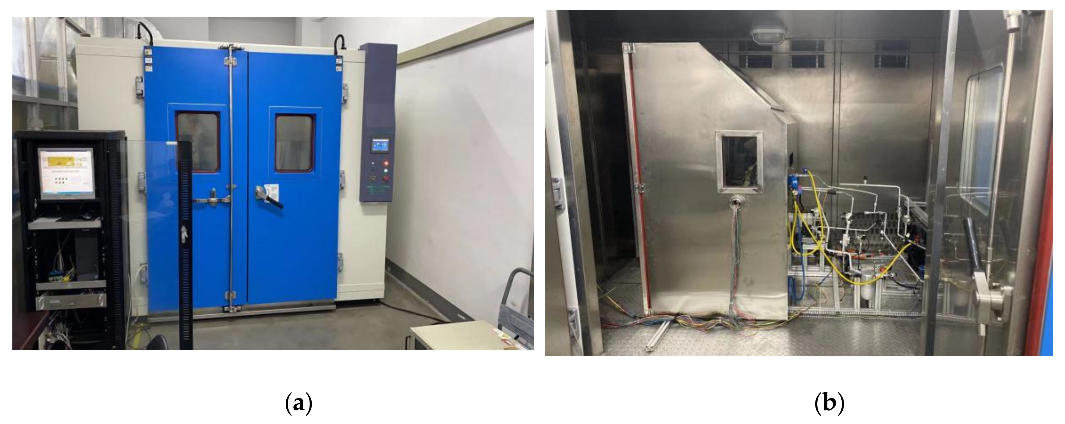
Figure 1 shows a schematic diagram of the test setup for the heating performance of HPACS, which consists of a compressor, internal condenser, external heat exchanger, internal evaporator, EXV, solenoid valves, thermal expansion valve (TXV), accumulator and the air doors. In the heating mode, the high-temperature and high-pressure refrigerant is discharged from the compressor 01, and flows through the solenoid valve 06, enters the internal condenser 04, and the air door 20 is open which rejects heat to the air that flows into cabin, and then passes through the electric expansion valve 08, the refrigerant becomes a low-temperature and low-pressure vapor–liquid mixture, the refrigerant then flows into the external heat exchanger 02, then flows into the accumulator 05, and finally the low-temperature and low-pressure refrigerant flows back to the compressor to complete the heating cycle. In this case, the solenoid valve 07 and solenoid valve 09 are closed. The experiments were conducted in an environmental cabin which can simulate any operating conditions for HPACS. Figure 2 shows the air conditioning test system bench.

2.2. Experimental Conditions and Mehod

In order to verify whether the designed HPACS can provide a suitable temperature for the cabin of BEV in winter. Combined with the thermodynamic cycle process of the HPACS in the heating mode, a system bench experiment was established to explore the effects of different ambient temperature, the air flow rate of the internal condenser, compressor speed, and EXV opening on system performance. The mass flow rate of refrigerant was measured using a micromotion mass flow meter, and the pressure and temperature was measured using an Omega sensor. The types and precision of each sensor are listed in Table 1. It is worth noting that the experiment of the best refrigerant charge was carried out under heating conditions at the start of the experiment. In this system, the best refrigerant charge is 800 g. The detailed operating conditions of HPACS are illustrated in Table 2.

2.3. Exergy Analysis

The research on the heating performance of HPACS is usually based on the heating capacity and heating coefficient COP. This is based on the first law of thermodynamics and analyzes the system performance from the “quantity” of energy.
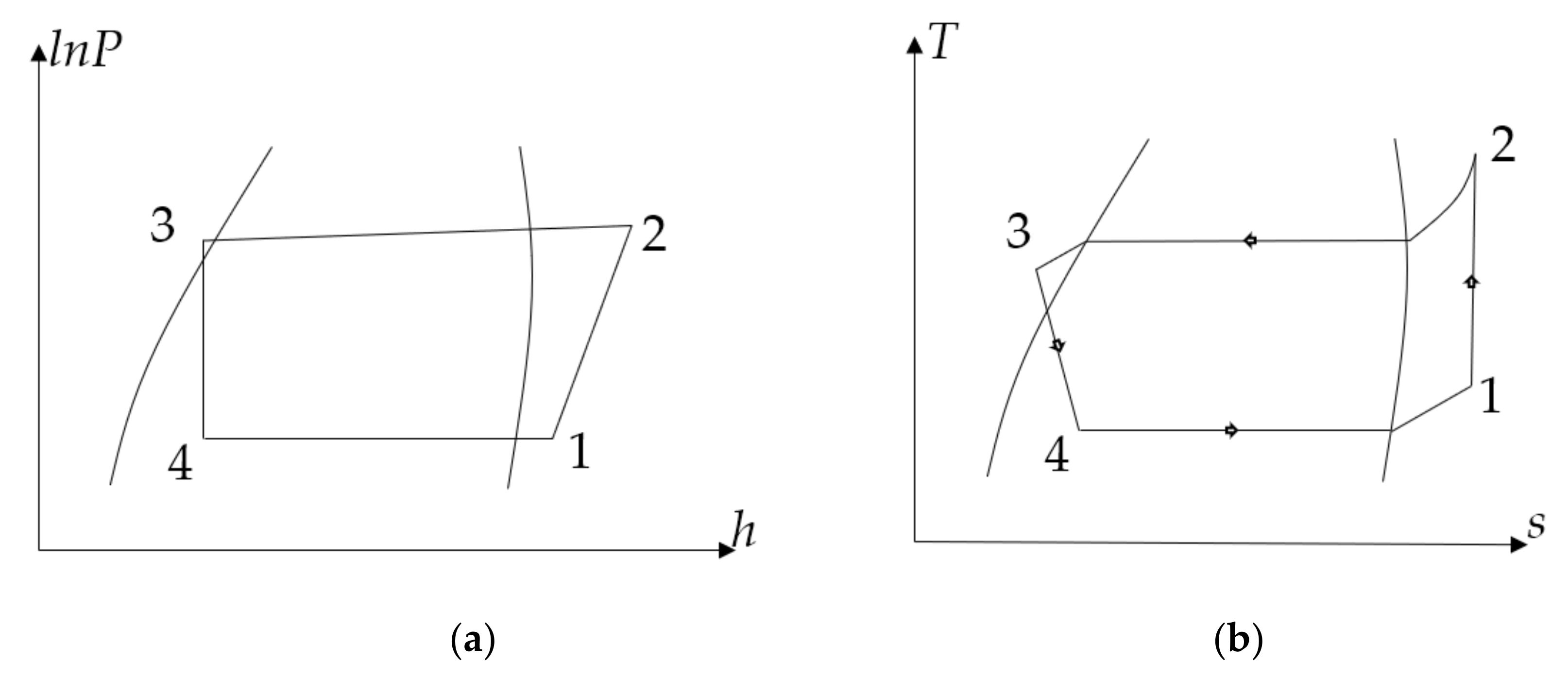
In fact, when the HPACS of BEV works, there is not only the process of energy transfer, but also the process of energy quality degradation. In this paper, the performance of the HPACS is comprehensively considered from the “quantity” and “quality” aspects of energy on the basis of the first and second laws of thermodynamics. The calculation of exergy loss and exergy efficiency is analyzed for each component (compressor, condenser, throttle, evaporator) and the system. The Figure 3 shows the lnP-h and T-s diagram of the HPACS in the theory heating mode. To perform exergy analysis and specify the exergy losses or destructions for each component of the HPACS, the following assumptions are made:
  • The conditions are steady-state.
  • The process in the compressor and expansion valve is adiabatic.
  • The changes in kinetic energy and potential energy are insignificant.
At this time, the specific physical exergy equation [27] of the system is stated as follows Equation (1):
e = h h 0 T 0 ( s s 0 )
where h 0 and s 0 represent the enthalpy and entropy at the ambient environment ( T 0 ).
For exergy analysis of each component, the main cause of exergy loss of the compressor is the non-isentropic property of working medium under compressor compression (it can be quantitatively described by the value of isentropic efficiency of compressor). The exergy destruction of condenser and evaporator is mainly related to the heat transfer of temperature difference. The exergy destruction in the expansion valve is due to the temperature and pressure drop of the working medium caused by the local resistance. The basic Equations (2)–(5) were employed to calculate the exergy losses of components
(1)
Compressor exergy losses
E comp = T 0 ( s comp,i s comp,e ) = T 0 ( s 1 s 2 )
(2)
Internal evaporator exergy losses
E cond = h eva,i h eva,e T 0 ( s eva,i s eva,e ) = h 4 h 1 T 0 ( s 4 s 1 )
(3)
Internal condenser exergy losses
E cond = h cond,i h cond,e T 0 ( s cond,i s cond,e ) ( h cond,i h cond,e ) ( 1 T 0 T cond ) = h 2 h 3 T 0 ( s 2 s 3 ) ( h 2 h 3 ) ( 1 T 0 T cond )
where T cond is condensing temperature.
(4)
Expansion process exergy losses
E val = T 0 ( s val,i s val,e ) = T 0 ( s 3 s 4 )
When the HPACS is in heating mode, the revenue exergy or heating exergy from internal condenser can be written as below with Equation (6):
δ E cond = ( h cond , i h cond , e ) ( 1 T 0 T cond ) = ( h 2 h 3 ) ( 1 T 0 T cond )
To describe the efficiency of energy utilization better in the thermal system, another concept, exergy efficiency, is often used, which refers to the proportion of revenue exergy in expenditure exergy. For the HPACS, the formula for calculating the exergy efficiency of heat pump is as follows Equation (7):
η = δ E cond w comp
where w comp is specific work of the compressor, kJ/kg;
The relationship between the exergy loss coefficients of the components reflects the distribution of the irreversible loss in the whole system. Therefore, the unreasonable structure in the system structure can be determined by exergy analysis so as to make targeted improvement.

3. Results and Discussion

3.1. Effect of Internal Condenser Air Flow Rate

The air flow rate of the internal condenser will directly affect the heat exchange performance of the internal condenser, thereby affecting the heating performance of HPACS. This section attempts to explore the effects of different air flow rates of the internal condenser on system related performance. During the operation of the HPACS, the compressor speed remains constant.
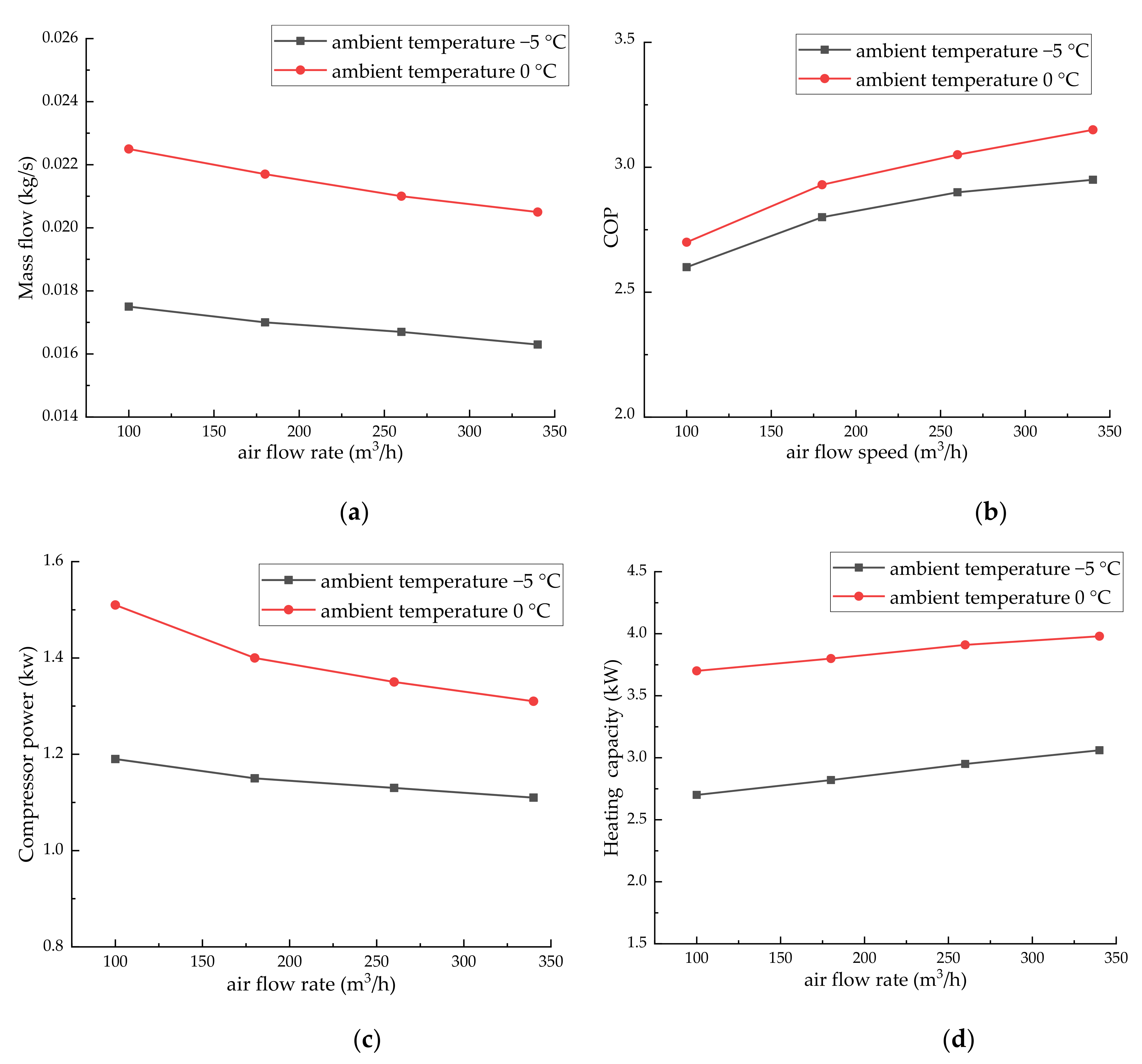
Figure 4 shows the effect of the different air flow rate (100, 180, 260, 340 m3/h) on the performance of the system including system refrigerant flow rate, heating capacity, compressor power consumption and COP. As shown in Figure 4, as the air flow rate of the internal condenser increased from 100 to 340 m3/h, when the ambient temperature is 0 °C, the heating capacity increased from 3.7 to 3.98 kW and the growth rate is 7%, the compressor work decreased from 1.51 to 1.31 kW and the reduction rate is 13.2%, the corresponding COP increased by 14.2%. When the ambient temperature is −5 °C, the heating capacity increased from 2.7 to 3.06 kW and the growth rate is 11.8%, the compressor power decreased from 1.19 to 1.11 kW and the reduction rate is 6.7%, the corresponding COP enhanced by 11.8%. Thus, more than a 10% improvement of COP could be achieved solely by air flow of the internal condenser, which indicates that the enhancement of the air flow rate of the internal condenser contributes to the enhancement of the heating capacity of the HPACS. This is because as the air flow rate of the internal condenser increases, enthalpy difference for the internal condenser will be greater and heat exchange performance becomes better.
Figure 5 focuses on the change of system exergy performance when exergy loss influences the coefficient and the exergy efficiency ratio of each component of the HPACS is calculated at different air flow rate of the internal condenser with the same ambient temperature (0 °C) and the compressor speed is at 4500 rpm.
As shown in Figure 5, the air flow rate of the internal condenser has little effect on the exergy losses of each component. In addition, the higher air flow rate will accelerate the heat exchange between the condenser and the environment, which leads to a much higher exergy efficiency.

3.2. Effect of Compressor Speed

The compressor speeds have an important impact on the power consumption and heating capacity of the HPACS. Figure 6 indicates that the heating capacity of the system enhanced by 1.46 kW and the growth rate is 33.6%, the compressor work increased by 0.64 kW and the growth rate is 44.8%, the corresponding COP decreased by 16.5% as compressor speed increased from 3000 rpm to 5500 rpm, when the ambient temperature is −5 °C. The heating capacity increased by 1.18 kW and the growth rate is 31.4%, the compressor work increased by 0.85 kW and the growth rate is 46.9%, the corresponding COP decreased by 22.6% as compressor speed increased from 3000 to 5500 rpm, when the ambient temperature is 0 °C. The result indicates that the increment of compressor speed contributes to improving the refrigerant flow rate and heating capacity of the system. In fact, this is because as the speed of the compressor increases, the mass flow rate of the refrigerant at the outlet of the compressor, exhaust pressure and temperature will increase, so refrigerant rejects heat capacity in the internal condenser becomes better, and the heat capacity of HPACS will increases.
Exergy loss influence coefficient and exergy efficiency ratio of each component of HPACS is calculated at different compressor speed with same ambient temperature (0 °C), and the air flow rate of the internal condenser is 260 m3/h. Figure 7 describes the result.
As shown in Figure 7, when compressor speed decrease from the highest speed of 5500 to the speed of 3000 rpm, the exergy destruction of compressor decreased by 18.2, the efficiency is increased about 10.9%. When ambient temperature is lower, in view of that there is a positive correlation between the heating performance of the HPACS and the speed of compressor, although lower compressor speed can improve exergy efficiency, it is not a reasonable way to minimize the speed of the compressor. To effectively reduce the exergy destruction of compressor, the compressor internal structure should be considered, for example, the friction loss of inlet and outlet valves should be reduced as much as possible.

3.3. Effect of Ambient Temperature

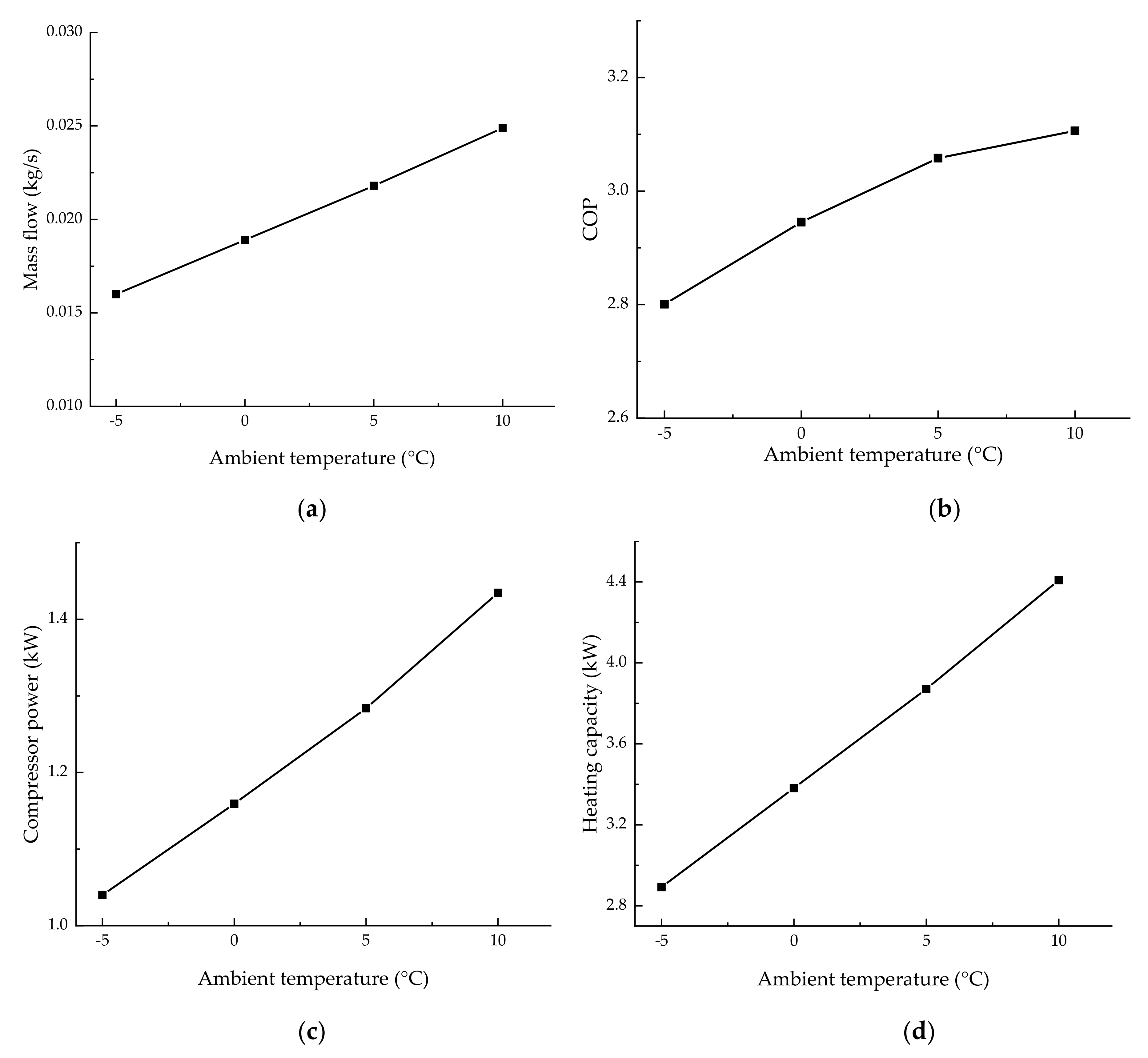
As shown in Figure 8, when the ambient temperature increased from −5 to 10 °C, the mass flow rate of the refrigerant increased from 0.015 to 0.0248 kg/s, the heating capacity increased from 2.9 to 4.4 kW, the compressor work decreased from 1.82 to 1.41 kW, and the corresponding COP increased by 9.7%. This is because that as the ambient temperature increases, the evaporation pressure and the fluid temperature and pressure at the outlet of external evaporator will rise. When the refrigerant enters the compressor, the increment in suction pressure and density causes the compressor discharge pressure and the refrigerant mass flow to increase, so heating capacity in the internal condenser will increase. Therefore, as the ambient temperature increases, heating capacity increases significantly. However, as the ambient temperature increases, the increase in suction pressure is greater than the increase in discharge pressure and refrigerant mass flow increases significantly, so compressor power will increase. Moreover, given that the heating capacity of the system has increased significantly and the power consumption of the compressor has increased slightly, this results in the system COP increasing as the ambient temperature increases.
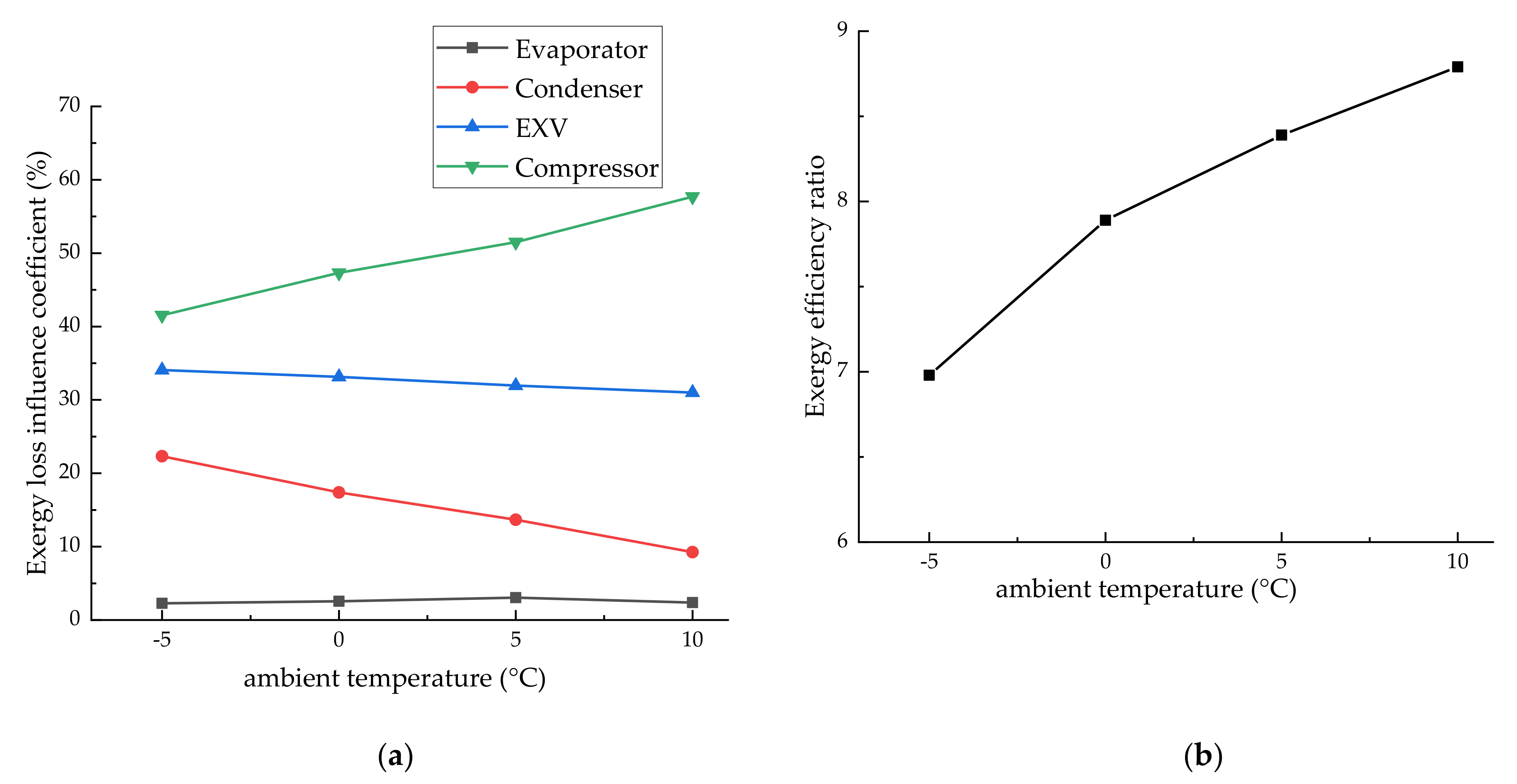
Figure 9 shows that the change of system exergy performance when the compressor speed is kept at 4500 r/min, the air flow rate of the internal condenser is 260 m3/h and the ambient temperature changes within the range of −5 to 10 °C.
As shown in Figure 9a, the evaporator exergy destruction of the evaporator accounts for only 4%, which is the smallest among all components. When the ambient temperature is higher, the exergy destruction of the system is mainly caused by the compressor, which means that in order to minimize system exergy destruction, the compressor should be optimized. In addition, the exergy efficiency of the HPACS is also computed, and the result is shown in Figure 9b, the exergy efficiency increases with the increment of ambient temperature, but the increasing extent is smaller and smaller.

3.4. Effect of EXV Opening

The EXV is one of the important components of the HPACS, and its opening will affect the performance of the HPACS. The operation parameters of the HPACS were measured under different EXV opening (50, 100, 150, 200, 250, 300 steps). Based on the experimental data, when the EXV opening increases from 50 to 300 steps, the system heating capacity and compressor power consumption are reduced, while the reduction in heating capacity is greater than the reduction in compressor power consumption, which accounts for the corresponding system COP slightly increasing, the result is illustrated in Figure 10.
Figure 11 shows that the change of system exergy performance when the compressor speed is at 4500 r/min, the air flow rate of the internal condenser is 260 m3/s and the EXV opening changes within the range of 50–300.
As shown in Figure 11, when the EXV opening increased from 50 to 300 steps, the exergy destruction of the evaporator increases, except the compressor, condenser and EXV and the exergy destruction of the evaporator increased 82%. As the results of the decrement of heating capacity and heating exergy of internal condenser, the exergy efficiency is smaller and smaller.

4. Conclusions

The system performance of HPACS with refrigerant R134a was investigated under different ambient temperature, the air flow rate of the internal condenser, EXV opening and compressor speed. The increment in the air flow rate of the internal condenser contributes to enhancing the heating capacity, which is required by the thermal comfort of the cabin of BEV, but its influence is smaller compared to the increment in compressor speed, when ambient temperature is at 0 °C, as the air flow rate of the internal condenser increases from 100 to 340 m3/h the heating capacity increased 7%, while compressor speed increases from 3000 to 5500 rpm, the heating capacity increased by 31.4%.
In addition, the refrigerant R134a is used as the working fluid in the HPACS, When the ambient temperature is −5 °C, and the HPACS can also provide the heating capacity required by the battery electric vehicle cabin, the heating capacity is 3.6 kW and the COP is 3.2, demonstrating that the system has high energy efficiency.
Furthermore, compressor exergy destruction is the highest among all components, accounting for 55% of the total. The percentage of exergy destruction in other components is about 28%, 12% and 5% for the expansive valve, condenser, and evaporator, respectively. Higher ambient temperature has a positive effect on increasing the exergy efficiency. To effectively improve the exergy performance of the HPACS, it is reasonable to increase the air flow rate of the internal condenser and the friction loss of inlet and outlet valves of compressor should be reduced as much as possible. Under the condition of ensuring heating capacity of the HPACS, when air flow rate of the internal condenser increased from 100 to 340 m3/h, the exergy efficiency ratio can be increased by about 53.7%. For the exergy destruction of heat exchanger components, it can be reduced by decreasing the heat transfer temperature difference. To sum up, in order to make the HPACS function in a high-performance state in heating mode, the compressor exergy destruction should be reduced as much as possible and air flow rate of the internal condenser should be increased on the premise of ensuring the comfort of the cabin, such as increasing the circulation area of the compressor and the air doors opening. In order to make the HPACS meet the requirements of lower temperature (below −10 °C), the supplementary HPACS or HPACS with CO2 refrigerant suitable for lower temperature should be discussed in the future.

Author Contributions

Conceptualization and theory tutor, M.L.; Experimental frame design and operating condition design, Q.G. and X.T.; Experimental data analysis, M.J. and X.T.; writing, X.T. and Q.G. All authors have read and agreed to the published version of the manuscript.

Funding

The authors wish to acknowledge for the financial support from Technology Breakthrough Project of Jilin Province Science and Technology department (Project No.20190302120GX), for the work reported in this paper.

Conflicts of Interest

The authors declare no conflict of interest.

Nomenclature

HPACSHeat Pump Air Conditioning System
COPCoefficient of Performance
BEVBattery Electric Vehicle
EXV Electrical Expansion Valve
TXVThermal expansion valve
IHXInternal Heat Exchanger
PTCPositive Temperature Coefficient
eSpecific exergy (kJ kg−1)
hEnthalpy (kJ kg−1)
sEntropy (kJ kg−1 K−1)
TTemperature (°C)
EExergy losses (kJ kg−1)
wSpecific work (kJ kg−1)
Greek letters
ηEfficiency
Subscript
condCondenser
compCompressor
evaEvaporator
0Ambient
iInlet
eExit
valExpansion Valve

References

  1. Granovskii, M.; Dincer, I.; Rosen, M.A. Economic and environmental comparison of conventional, hybrid, electric and hydrogen fuel cell vehicles. J. Power Sources 2006, 159, 1186–1193. [Google Scholar] [CrossRef]
  2. Yang, F.; Xie, Y.; Deng, Y.; Yuan, C. Predictive modeling of battery degradation and greenhouse gas emissions from U.S. state-level electric vehicle operation. Nat. Commun. 2018, 9, 2429. [Google Scholar] [CrossRef]
  3. Khayyam, H.; Kouzani, A.Z.; Hu, E.J.; Nahavandi, S. Coordinated energy management of vehicle air conditioning system. Appl. Therm. Eng. 2011, 31, 750–764. [Google Scholar] [CrossRef]
  4. Higuchi, Y.; Kobayashi, H.; Shan, Z.; Kuwahara, M.; Endo, Y.; Nakajima, Y. Efficient heat pump system for PHEV/BEV. SAE Int. 2017. [Google Scholar] [CrossRef]
  5. Kumar, V.; Shendge, S.A.; Baskar, S. Underhood thermal simulation of a small passenger vehicle with rear engine compartment to evaluate and enhance radiator performance. SAE World Congr. Exhib. 2010. [Google Scholar] [CrossRef]
  6. Gao, Q.; Qian, Y.; Fei, G.; Yan, Y. Methodology for thermal analysis of multi-system in engine underhood. Automot. Eng. 2012, 2, 8–15. [Google Scholar] [CrossRef]
  7. Yuan, X.; Gu, Z.; Yang, Y.; Yuan, Z.; Jiang, L.; Su, W. Numerical simulation on vehicle underhood cooling. Automot. Eng. 2009, 31, 843–847. [Google Scholar] [CrossRef]
  8. Li, X.; Zhu, L.; Liu, X.; Xiong, F.; Shang, J.; Yang, B. Thermal modeling and sensitivity analysis of a traction motor in a production EV. SAE Tech. Pap. 2019. [Google Scholar] [CrossRef]
  9. Zhou, G.; Li, H.; Liu, E. Experimental study on combined defrosting performance of heat pump air conditioning system for pure electric vehicle in low temperature. Appl. Therm. Eng. 2017, 116, 677–684. [Google Scholar] [CrossRef]
  10. Tan, H.; Zhang, X.; Zhang, L.; Tao, T.; Xu, G. Ultrasonic Guided Wave Phased Array Focusing Technology and Its Application to Defrosting Performance Improvement of Air-Source Heat Pumps. Energies 2019, 12, 3117. [Google Scholar] [CrossRef] [Green Version]
  11. Song, M.; Deng, S.; Dang, C.; Mao, N.; Wang, Z. Review on improvement for air source heat pump units during frosting and defrosting. Appl. Energy 2018, 211, 1150–1170. [Google Scholar] [CrossRef]
  12. Choi, Y.U.; Kim, M.S.; Kim, G.T.; Kim, M.S. Performance analysis of vapor injection heat pump system for electric vehicle in cold startup condition. Int. J. Refrig. 2017, 80, 24–36. [Google Scholar] [CrossRef]
  13. Kim, K.Y.; Kim, S.C.; Kim, M.S. Experimental studies on the heating performance of the PTC heater and heat pump combined system in fuel cells and electric vehicles. Int. J. Automot. Technol. 2012, 13, 971–977. [Google Scholar] [CrossRef]
  14. Hosoz, M.; Direk, M. Performance evaluation of an integrated automotive air conditioning and heat pump system. Energy Convers. Manag. 2006, 47, 545–559. [Google Scholar] [CrossRef]
  15. Piccolo, A.; Siclari, R.; Rando, F.; Cannistraro, M. Comparative Performance of Thermoacoustic Heat Exchangers with Different Pore Geometries in Oscillatory Flow. Implementation of Experimental Techniques. Appl. Sci. 2017, 7, 784. [Google Scholar] [CrossRef] [Green Version]
  16. Cao, J.; Chen, C.; Gao, G.; Yang, H.; Su, Y.; Michele, B.; Mauro, C.; Pei, G. Preliminary evaluation of the energy-saving behavior of a novel household refrigerator. J. Renew. Sustain. Energy 2019, 11, 015102. [Google Scholar] [CrossRef]
  17. Cao, J.; Chen, C.; Hu, M.; Wang, Q.; Mauro, C.; Michael, K.H.L.; Pei, G. Numerical analysis of a novel household refrigerator with controllable loop thermosyphons. Int. J. Refrig. 2019, 104, 134–143. [Google Scholar] [CrossRef]
  18. Li, W.; Liu, R.; Liu, Y.; Wang, D.; Shi, J.; Chen, J. Performance evaluation of R1234yf heat pump system for an electric vehicle in cold climate. Int. J. Refrig. 2020, 115, 117–125. [Google Scholar] [CrossRef]
  19. Wu, J.; Zhou, G.; Wang, M. A comprehensive assessment of refrigerants for cabin heating and cooling on electric vehicles. Appl. Therm. Eng. 2020, 174, 115258. [Google Scholar] [CrossRef]
  20. Peng, X.; Wang, D.; Wang, G.; Yang, Y.; Xiang, S. Numerical investigation on the heating performance of a transcritical CO2 vapor-injection heat pump system. Appl. Therm. Eng. 2020, 166, 114656. [Google Scholar] [CrossRef]
  21. Wang, D.; Yu, B.; Hu, J.; Chen, L.; Shi, J.; Chen, J. Heating performance characteristics of CO2 heat pump system for electrical vehicle in a cold climate. Int. J. Refrig. 2018, 85, 27–41. [Google Scholar] [CrossRef]
  22. Wu, D.; Hu, B.; Wang, R. Performance simulation and exergy analysis of a hybrid source heat pump system with low GWP refrigerants. Renew. Energy 2018, 116, 775–785. [Google Scholar] [CrossRef]
  23. Taslimi Taleghani, S.; Sorin, M.; Poncet, S. Analysis and Optimization of Exergy Flows inside a Transcritical CO2 Ejector for Refrigeration, Air Conditioning and Heat Pump Cycles. Energies 2019, 12, 1686. [Google Scholar] [CrossRef] [Green Version]
  24. Cho, H.; Park, C. Experimental investigation of performance and exergy analysis of automotive air conditioning systems using refrigerant R1234yf at various compressor speeds. Appl. Therm. Eng. 2016, 101, 30–37. [Google Scholar] [CrossRef]
  25. Chen, J.; Havtun, H.; Palm, B. Conventional and advanced exergy analysis of an ejector refrigeration System. Appl. Energy 2015, 14, 139–151. [Google Scholar] [CrossRef]
  26. Chen, J.; Havtun, H.; Palm, B. Investigation of ejectors in refrigeration system: Optimum performance evaluation and ejector area ratios perspectives. Appl. Therm. Eng. 2014, 64, 182–191. [Google Scholar] [CrossRef]
  27. Shen, M.; Gao, Q.; Wang, Y.; Zhang, T. Design and analysis of battery thermal management system for electric vehicle. J. Zhejiang Univ. 2019, 53, 1398–1406. [Google Scholar] [CrossRef]
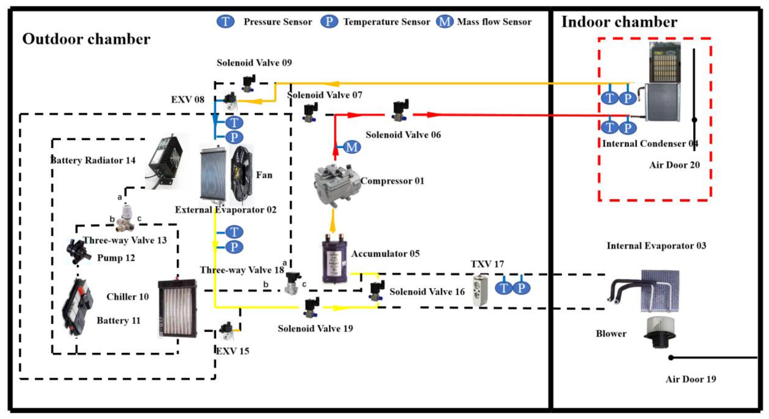
Figure 1. Schematic of the heat pump air conditioning system.
Energies 13 02868 g001
Figure 2. Heat pump air conditioning system (HPACS) test system bench. (a) Control room and environment cabin, (b) Test bench.
Energies 13 02868 g002
Figure 3. lnP-h and T-s diagrams of the heat pump cycles. (a) P-h diagrams, (b) T-s diagrams.
Energies 13 02868 g003
Figure 4. Effects of internal condenser air flow rate on the system performance. (a) Refrigerant flow rate, (b) coefficient of performance (COP), (c) compressor power, (d) heating capacity.
Energies 13 02868 g004
Figure 5. Effects of air flow rate on exergy loss influence coefficient and exergy efficiency. (a) Exergy loss influence coefficient; (b) exergy efficiency.
Energies 13 02868 g005
Figure 6. Effects of compressor speed on the system performance. (a) Refrigerant flow rate, (b) COP, (c) compressor power, (d) heating capacity.
Energies 13 02868 g006
Figure 7. Effects of compressor speed on exergy loss influence coefficient and exergy efficiency. (a) Exergy loss influence coefficient; (b) exergy efficiency.
Energies 13 02868 g007
Figure 8. Effects of ambient temperature on the system performance. (a) Refrigerant flow rate, (b) COP, (c) compressor power, (d) heating capacity.
Energies 13 02868 g008
Figure 9. Effects of ambient temperature on exergy loss influence coefficient and exergy efficiency. (a) Exergy loss influence coefficient, (b) exergy efficiency.
Energies 13 02868 g009
Figure 10. Effects of expansion valve (EXV) opening on the system performance. (a) Refrigerant flow rate, (b) COP, (c) compressor power, (d) heating capacity.
Energies 13 02868 g010
Figure 11. Effects of EXV opening on exergy loss influence coefficient and exergy efficiency. (a) Exergy loss influence coefficient, (b) Exergy efficiency.
Energies 13 02868 g011
Table 1. Sensor type and precision.
Measurement ParameterSensor TypeRangePrecision
Temperature/°COmega temperature sensor−50–200±0.1
Pressure/kPaOmega pressure sensor0–4000±5
Mass flow rate (kg/h)Micromotion mass flow meter0–200±0.5
Table 2. Operating conditions of HPACS.
Ambient Temperature (°C)Compressor Speed (rpm)Air Flow Rate of the Internal Condenser (m3/h)Expansion Valve Opening
103000–5500100–34050–300
53000–5500100–34050–300
03000–5500100–34050–300
−53000–5500100–34050–300