Article

Management and Performance Control Analysis of Hybrid Photovoltaic Energy Storage System under Variable Solar Irradiation

by
Mohamed Louzazni
1,
Daniel Tudor Cotfas
2,* and
Petru Adrian Cotfas
2
1
National School of Applied Science, Abdelmalek Essaâdi University, Tetouan B.P. 2117, Morocco
2
Department of Electronics and Computers, Transilvania University of Brasov, Eroilor 29, 500036 Brasov, Romania
*
Author to whom correspondence should be addressed.
Energies 2020, 13(12), 3043; https://doi.org/10.3390/en13123043
Submission received: 11 May 2020 / Revised: 7 June 2020 / Accepted: 10 June 2020 / Published: 12 June 2020
(This article belongs to the Special Issue Solar Hybrid Power Systems)

Abstract

:
This paper introduces the management control of a microgrid comprising of photovoltaic panels, battery, supercapacitor, and DC load under variable solar irradiation. The battery is used to store the energy from the photovoltaic panels or to supply the load. The supercapacitor is used to reduce stress on batteries, improve their life cycle, and absorb the fluctuations in the energy produced. The generated photovoltaic power is optimized using Perturb and Observe and Incremental Conductance algorithms to extract the maximum power point tracking. The two algorithms are modified by adding an instantaneous step size to change the direction of the power, so as to reach the maximum power point tracking. The currents of the battery and supercapacitor are managed and controlled using the multi-loop proportional integral controllers. The obtained results show that the multi-loop proportionally integral controllers Perturb and Observe are better than the multi-loop proportional integral controllers Incremental Conductance in terms of stability of injected power. The storage system works perfectly for energy supply, system protection, and fluctuation absorption during the transitions in the solar irradiation. The proposed hybrid storage system can be installed in rural areas as an off-grid system for several uses.

Graphical Abstract

1. Introduction

1.1. Background

Recently, the domains of renewable energy sources and particularly photovoltaic systems have undergone rapid development and have become extremely popular. Renewable energy offers a sustainable solution for the production of inexhaustible energy and sustainability for the ecosystem [1]. Due to its lower maintenance costs and low emissions, photovoltaic system electricity production became the primary source of renewable energy and can considerably reduce the system fuel costs. The main challenges are the instability, nonlinearity, and complexity of the photovoltaic characteristics. Moreover, its production is highly dependent on the weather conditions, cable losses, dust accumulation, shading and soiling [2]. Nevertheless, the photovoltaic generator is widely used in various fields to produce the electricity in off-grid or grid connected with storage system. For instance, the photovoltaic system is used with battery and supercapacitor as off-grid hybrid photovoltaic system to store the energy and supply the load when there is no energy produced from the main source of the system as a secondary source [3]. Currently, battery and supercapacitor storage systems present a significant possibility to overcome the problems of load requirement and power generation fluctuations.
The implementation of the photovoltaic system can be classified in two main categories: grid connected and stand alone. The stand alone or off-grid photovoltaic is used for producing the energy for basic electricity needs [4]. In off-grid, the photovoltaic system cannot provide the electricity to the load at night or when a change in the solar irradiation occurs due to the shading or fault. The energy used in grid connected or in off-grid systems from the energy generated by the photovoltaic panels is optimized if the maximum power point tracker (MPPT) algorithms are used.

1.2. Literature Review

Several papers have presented the optimization of the MPPT using different techniques to inject the maximum power to the system [5]. For example, a programmable DC power supplies has been used to control the MPPT [6]. A regression method was presented to analyze and study the photovoltaic system in different weather conditions [7]. The Lagrange multiplier method is an analytical and mathematical method to optimize the current and voltage [8]. Nguyen et al. presented a linearization of the photovoltaic model using the Thevenin equivalent circuit, to optimize the operation point and to reduce the impact of rapid change in solar irradiation [9]. The system control is based on the relationship between the pulse-width modulation (PWM) duty cycle and the output of the photovoltaic using the linearization model. The results show that the linearization model improves the produced power from the photovoltaic system and reduces the impact of any change in the solar irradiation. A geometrical method based on the power–voltage curve of the photovoltaic panel combined with Lagrangian interpolation and quadratic regression was presented to improve the optimization of the current and voltage [10]. The comparison between the Perturbed and Observe (P&O) algorithm and the geometrical method shows that the latter is able to extract a stable MPPT under noise in the measurements. Balato et al. made a review and analysis of the main advantages of the distributed MPPT and reconfigurable photovoltaic system, by combining the two approaches [11]. The study presents that the combination has a positive effect in energy efficiency and increases the reliability of the photovoltaic system mismatch. A combination between fuzzy logic controller and genetic algorithm is presented in order to optimize the performance yield of photovoltaic system using the triangle fuzzy logic rules [12]. Results are compared with the P&O algorithm and show that the hybrid technique can improve the optimization of the tracking operation point in terms of output power and energy yield. Lazaroiu et al. presented the analysis comparison between fixed and sun tracking of low photovoltaic module systems connected to electrochemical battery used as a load [13]. The results presented showed that the sun tracking presents better results in the morning and evening than the fixed photovoltaic module. However, the sun tracking is limited on partially clear sky or on cloudy days, thus the author proposes more research to be conducted so as to overcome the impediment.
The sun tracking assessment has been applied to crystalline silicon photovoltaic module, so as to analyze its performance under variable weather conditions [14]. The results also showed that the tracking system is better than the fixed photovoltaic system by 25%. In the hybrid photovoltaic system, Sahin et al. presented a sensor sun tracking by using an optical design, utilizing fisheye lens with low deviation and high-resolution integrated [15]. The model can be integrated with commercial image sensor array for MPPT. In other works, in High Concentration Photovoltaics, the authors used the optical design conventional fabrication methods [16]. Ju et al. detailed a review and a comparison between the stand-alone photovoltaic system and concentrated solar power [17]. The results proved that the photovoltaic system has several advantages in comparison with the concentrated solar power in terms of better power quality and higher generating efficiency.
The meta-heuristic algorithms, such as cuckoo search algorithm [18] and particle swarm optimization [19], are also used to optimize the output power of the photovoltaic panels in extracting the operation point or to optimize the injected energy from the boost converter. However, any method has limitations and disadvantages, such as slow convergence and perturbation in the operation point. The meta-heuristic algorithm and artificial intelligence approaches are computationally demanding, and their implementation is not easy. Among all the existent techniques, the P&O and Incremental Conductance (INC) algorithms are the most widely used for their simple implementation, few parameters being required and convergence [9]. These two algorithms are still working under several conditions even though they have several disadvantages and researchers are still proposing different modifications to improve them. The simple implementations of the two algorithms offer an easy manipulation and modification in the program to improve the convergence time and the efficiency of the system.
Commonly, the integration of the storage system with renewables energy source has been widely used in several locations under different weather conditions. Jing et al. presented a systematic comprehensive study review of the integration of the battery/supercapacitor and their feasibility for an off-grid photovoltaic system in rural electrification [4]. Jing et al. presented a numerical simulation and the control management of the storage system under varying solar irradiation to analyses the effectiveness in mitigating battery stress. The diesel source can also be added to the hybrid photovoltaic system. This system is controlled and discussed in [20] for Shipboard Microgrids. A proportional integral (PI) controller and low pass filter were used to control the energy management to eliminate the fluctuations. Tofighi et al. presented the management control of the photovoltaic system and battery storage system using the PI and passivity-based controllers [21]. This control manages the power between the components of the hybrid system. In other research, Luta et al. optimized the sizing of the fuel cell to the photovoltaic system and supercapacitor for commercial load [22]. The appropriate design is implemented on the basis of its technological reliability and cost-effectiveness. Usually the hybrid system is connected to load via a DC capacitance, considering that the battery has a high storage capacity and the supercapacitor can provide high levels of power. In this context, an analysis and evaluation management control of the DC voltage is presented, in order to reduce stress on batteries and improve their life cycle [23]. On the other hand, the power management in hybrid system is optimized using Mine-Blast Optimization algorithm to optimally manage the distribution of the energy in the system [24]. However, the integration of a storage system into a photovoltaic system offers an opportunity to improve the responses of voltage and current, particularly during changes in solar irradiance and variations in the demand for energy. Then, the battery and the supercapacitor are used specially to store the unused energy, protect the system, absorb the fluctuation, and provide stable electricity to the loads. Battery is the conventional storage system integrated to the photovoltaic system for its high energy density. However, the battery has several problems, like weak dynamic response and low charge/discharge rate [25]. On the other hand, supercapacitors can provide significantly higher currents than batteries and lower power density [26]. In comparison, the charging and discharging speeds of the supercapacitor are far too high compared to the battery. To overcome the several problems in off-grid hybrid energy systems, such as the nonlinear characteristics of the photovoltaic panel, the variation of solar irradiation, low power density and charging/discharging speed, the integrations of the battery and supercapacitor are suitable to provide the stable electricity to the load [4]. The photovoltaic system is optimized to inject the maximum power to the load and to charge the battery and supercapacitor. The storage system is controlled to manage the use of the energy, and to protect the system from overcharge and over discharge.

1.3. Contributions

Therefore, this paper aims to present a hybrid system by combination of the supercapacitor, battery, and photovoltaic array under varying fluctuation in the solar irradiation. A modification in the P&O and INC algorithms is introduced to optimize the photovoltaic system, by using the instantaneous step size from the slope of the power–voltage curve. A multi-loop control was designed in order to control the current in the battery and supercapacitor, and the voltage of the load. The control is designed and composite from the PI controller connected in series and parallel to minimize the errors and maintain the current and voltage to the desired value. Generally, the objective of this paper can be designed and implemented in the following six conditions:
  • Optimization of the power generated by photovoltaic system,
  • Balancing the voltage of the DC voltage to the appropriate value,
  • Control and management of the currents to their corresponding values in the supercapacitor and battery,
  • Reduce the stress in the battery by using the supercapacitor,
  • Protect the system from charge/discharge or surcharge and maintain it to the global stabilization,
  • Regulate the transfer of the energy between the hybrid system and DC-link.
The energy produced by the photovoltaic array mainly depends on solar irradiation, which introduces several problems in the power transformed to the load. In order to overcome the changes in the solar irradiation, an optimization algorithm is used to extract the maximum power point (MPP) of the photovoltaic array. To reach the operation point without perturbation or fluctuation of the photovoltaic array, an optimization using P&O and INC algorithms is used to inject the maximum power to the storage system and to the load under varying fluctuation of the solar irradiations. The two algorithms are modified in order to improve the fast convergence for finding the operation point around the operation point without oscillation to ensure more stability to the transformed energy. The improvement modification of the P&O algorithm is the use of the small instantaneous perturbation step in the ΔV to perturb the slope dP/dV in order to modify the direction of the ΔP to be around the operation point. The small instantaneous step size with scaling parameter is given based on the value dP/dV taken from the power–voltage curve to modify the perturbation step in ΔV. In addition, the duty cycle is perturbed when the ΔP in the P&O step changes the direction in the power–voltage curve to locate the operating point around the maximum power point. The step instantaneous size with the scaling parameters is automatically adjusted throughout the initialization process at start-up to maintain adequate operation under all initialization conditions. The duty cycle is modified to start with small values for automatic adjustment of the scaling parameter. The scaling parameter is determined in function of ΔV, ΔP from the power–voltage curve of the photovoltaic panel and Δd, the duty cycle of the boost converter.
On the other hand, the INC algorithm is similar to the P&O algorithm, and based on comparing the instantaneous values I/V and the dI/dV from the power–voltage slope by supposing that the second value is zero in the MPP [27,28]. The direction of the operation point is also dependent on the value of dI/dV, which is taken from the derivation of the power where P = V.I. A step size is used based on the scaling parameter in function of power, voltage, and duty cycle of the boost converter to change the direction of the operation point to reach the MPP. The scaling parameter determines the convergence time of the algorithm.
The DC-link voltage and the energy management strategy between the storage system and load are controlled trough a bidirectional converter using the multi-loop using 3-PI controllers. The objective from the multi-controller is to set up the supercapacitor as a complementary energy storage source in order to increase the dynamic charge/discharge stress on the battery. Additionally, the currents of the battery and supercapacitor are controlled to maintain the global system stabilization. The DC voltage is controlled and managed to its desired value. The management control regulates the transfer of the energy between the photovoltaic array, battery, supercapacitor, and the DC-link of the load. This planned control technique uses a supercapacitor throughout rapid changes and avoids the charge/discharge of the battery. The battery is used to store the unused energy from photovoltaic system and to support the load if there is no solar irradiation or the photovoltaic cannot supply the desired energy. This method eliminates the unwanted charge/discharge of the battery, stops the battery from being drained and, as a result, decreases the operating costs of the off-grid photovoltaic system and improves the battery life. As a result, the P&O algorithm is better than the INC algorithm in terms of the efficiency of the injected energy and in the integral absolute error under varying change in solar irradiations. The hybrid system under study can be a solution for the domestic applications in rural areas or for other applications.
The remainder of the paper is structured as follows: Section 2 presents and illustrates the hybrid energy storage (HES) system configuration and modelling of the photovoltaic panel, battery, and supercapacitor. Section 3 presents the optimization of the MPP of the photovoltaic, and demonstrates the control management of the DC-link voltage in the battery and supercapacitor. Section 4 presents the simulation results and comparative analysis of the P&O and INC optimization in terms of the injected energy to the load. Finally, the conclusion has been drawn in Section 5.

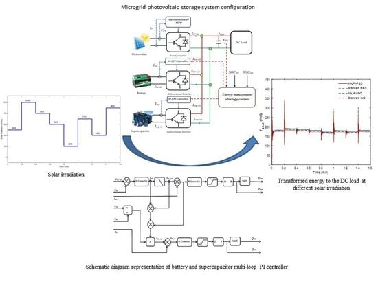
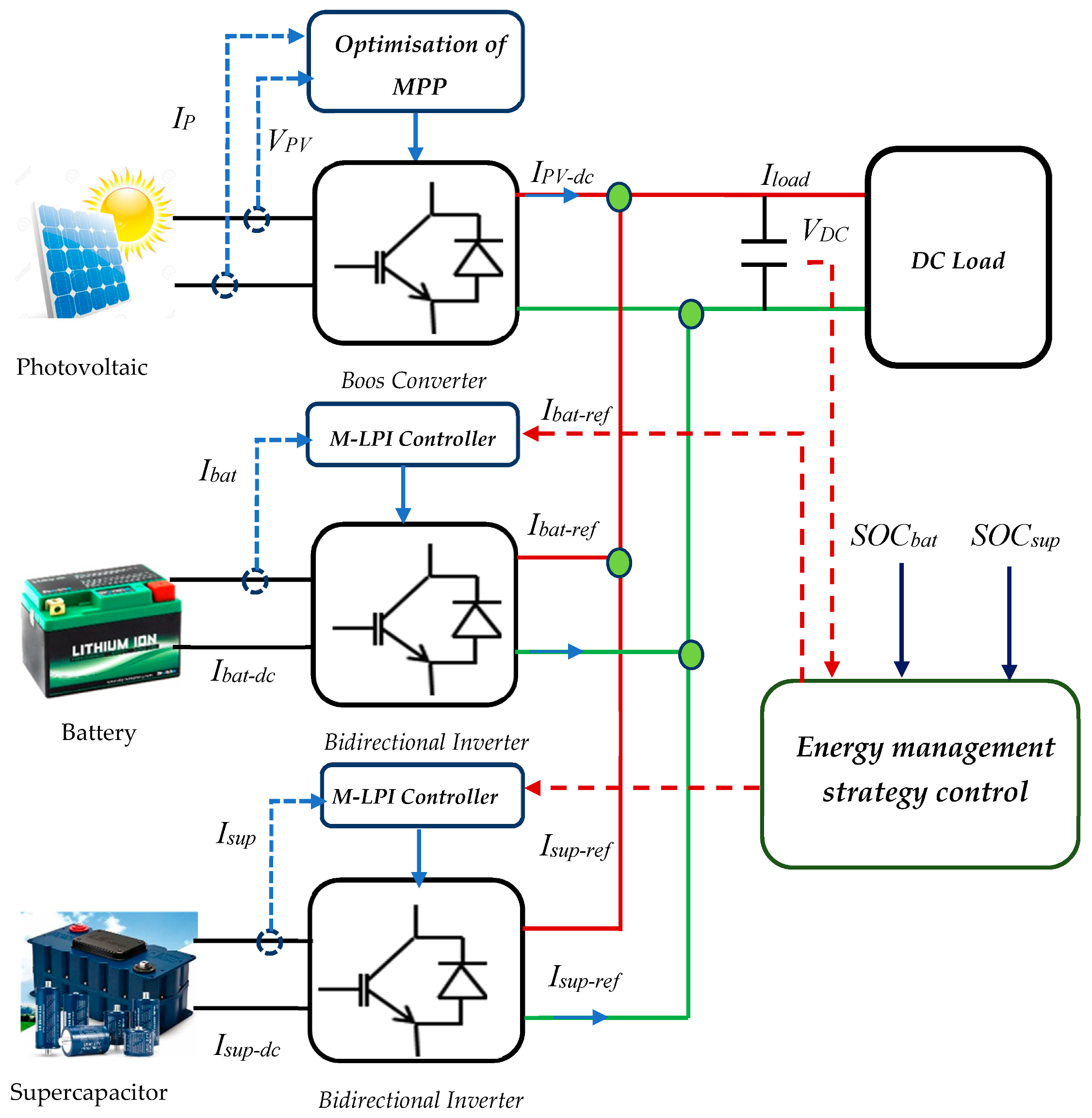
2. Hybrid Energy Storage System Configuration and Modelling

For this study, a DC–DC microgrid configuration is considered. It consists of a photovoltaic system as its main energy source and battery, both interfaced directly at DC-link and connected to the load, as shown in Figure 1. This configuration is considered as the best solution which uses multiple converters using double bidirectional buck converters separately connected to the battery and supercapacitor. The microgrid is supported by a HES comprising a battery and a supercapacitor (SC) directly connected to a DC-link capacitor through bidirectional DC–DC converters. The HES is connected to DC-link capacitor which generates and transfers the energy to a DC load under change in solar irradiation. The photovoltaic system is connected to the boost converter which controls the maximum power point, and the HES supports simultaneously steady-state and intermittent power generation and load demand adjustments. The photovoltaic system generates and delivers variable energy to the load influenced by the weather fluctuation. SC is used to support and absorb the transient/fluctuating as well as oscillatory power shifts, however, according to its limited power capacity. It is unable to supply/absorb continuous power shifts (long-term) because of the low internal resistance and low voltage. SCs are described by their highly particular power. SCs are effective in very rapid charging and discharges and have a very significant number of cycles with great performance and without degradation. The battery is used to store the generated energy from the photovoltaic generator and used later if needed. Additionally, it appears to support the continuous power changes due to its high-power density and supply transient power only under critical conditions [3]. A bidirectional inverter is used to transmit and receive energy from the charging storage system through a DC-bus interface. This source has a substantial mass energy and offers energy storage and weak system dynamics and is considered an important way to reduce the fluctuations in energy.

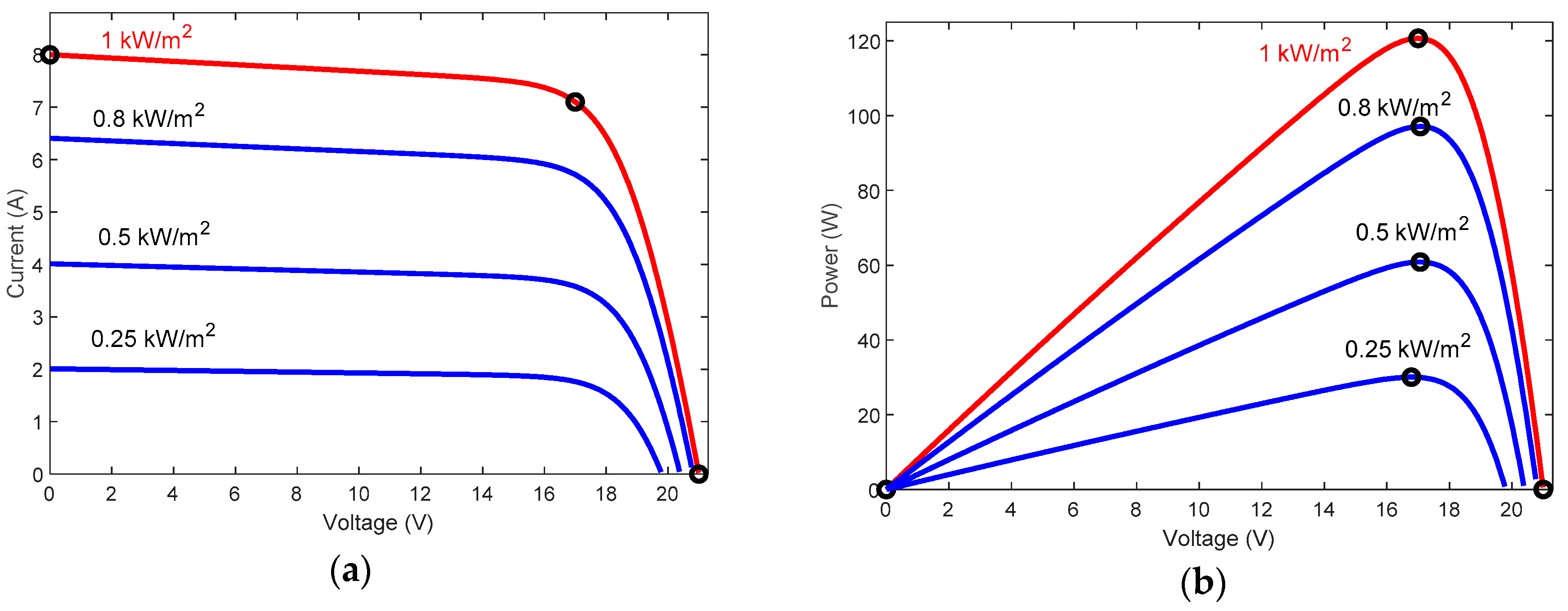
2.1. Photovoltaic Modelling

In this paper, a Waaree energies WU-120 photovoltaic array, manufactured by Waaree Energies Ltd with 6 parallel strings and 2 series-connected modules per string, is utilized as a case study [29]. Each photovoltaic module generates 120.7 W and contains 72 cells per module. Figure 2 presents the electrical characteristics current-voltage and power–voltage curves, which is connected to DC–DC converter to adjust the required DC power based in the load. A DC-link capacitor (CDC) is used to connect the boost converter to the load. The mathematical modelling of solar cell and photovoltaic model is given with detailed description and parameters extraction in [2,30,31,32,33]. Mutarraf et al. implemented the Waaree Energies photovoltaic module connected to diesel, battery, and ultra-capacitor systems for a control management of shipboard microgrids [20]. The current output of the photovoltaic module characteristic of photovoltaic is non-linear and is given as:
I = N p I p h N p I s ( e N p V + N s I R s n N p N s V T 1 ) N p V + N s I R s N s R s h
where, Vpv, and Ipv represent the voltage and current generated by the photovoltaic, Iph is the photo-current, Is is the saturation current of the diode, Rs and Rp are the parallel and series resistors, respectively. The Ns and Np are the number of solar cells connected in series and parallel, respectively, n is the ideality factor of diode and VT is the thermal voltage.
The dynamical behavior of photovoltaic module connected to the boost converter can be modelled as [34]:
d V p v d t = 1 C ( I p v I L )
where C is the input capacitor and IL is the current passing through the load, given as:
d I L d t = 1 L [ V p v V c ( 1 d ) ]
where L is the inductor in the boost converter, Vc is the voltage across the capacitor, and d is the switching duty cycle of the boost converter.
The voltage (Vdc) of DC-link capacitor is given as:
d V d c d t = 1 C d c [ I L V d c R L ( 1 d ) ]
where RL is the resistance of the load.
It is observed that the energy generated from the photovoltaic system depends on the solar irradiance, cell temperature, and efficiency of the system components, so there is always a specific point recognized as MPP (or MPPT if using a tracking method) at which the maximum power is available from photovoltaic system to supply the load with the required energy power. Hence, in certain circumstances, the maximum power must be available. Otherwise, the MPP and MPPT should be controlled via the MPP method (MPPT inverter control) to control the power yield from the photovoltaic array. In particular, the DC–DC boost converter is the most important element of MPP control, as it controls the duty cycle (d).
The equivalent resistance Requ of the boost converter can be written as:
R e q u = R L ( 1 d ) 2
According to Equation (5), the maximum quantity of energy will be delivered to the load when Requ is equal to the Thevenin resistance of the photovoltaic system [6,35].

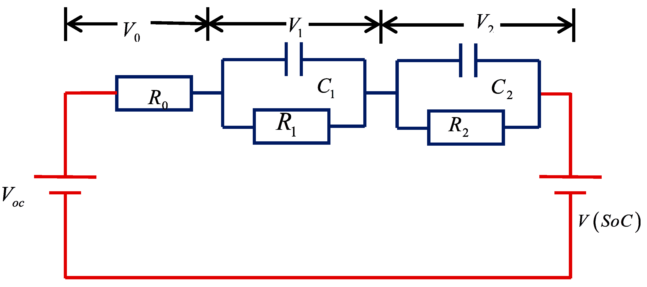
2.2. Lithium–Ion Battery Modelling

The battery banks are electrochemical structures that store the energy for later possible usage from several other AC or DC renewable energy or fossil sources [1]. The battery model is a regulated voltage source with a series resistor and power conditioning system, as presented in Figure 3 [36]. Lithium–ion batteries are widely used for their advantages in comparison to other battery types because they have high capacity of storage, high concentrations of functioning voltage and long cycle life [21]. During the off-peak hours, batteries usually absorb power from the grid and discharge power at peak demand.
The equivalent circuit model depicted in Figure 3 has a main reaction circuit that defines the charging/discharging cycle, and an alternative reaction circuit that is responsible for long-term battery degradation. The resistor R0 presents the ohmic resistance, which includes the resistance of contacts and electrodes. The double pair RC captures the transient battery dynamics such as the charge transfer kinetics and lithium ion diffusion [37]. The VOC is the open circuit voltage which depends mainly on the battery state-of-charge (SOC) [38]. The SOC curve is nonlinear and approximated by VOC = a+b × SOC with a and b are constant in the ith SOC interval.
In addition, the battery SOC ϵ (0%,100%) could be determined using the conventional Coulomb counting method [39].
S O C ( t ) = S O C ( t 0 ) η t 0 t I b a t ( τ ) C n d τ
where, η is the Coulombic efficiency; Cn (Ah) is the battery usable capacity; SOC(t) is the required SOC at time point t based on its initial value SOC(t0).
Whereas the dynamic operation of the battery can be represented by the corresponding interpretation of state-space:
[ d V 1 d t d V 2 d t d s o c ( t ) d t ] = M [ V 1 ( t ) V 2 ( t ) s o c ( t ) ] + N I b a t ( t ) V b a t ( t ) = V o c ( s o c ) V 1 ( t ) V 2 ( t ) R 0 I b a t ( t )
where,
M = [ 1 R 1 C 1 0 0 0 1 R 2 C 2 0 0 0 0 ] , N = [ 1 C 1 1 C 2 η C n ]
where Vbat is the battery output voltage, V1 and V2 are the voltages across the capacitors C1 and C2, respectively; Ibat is the battery input current.
The battery capacity Cbat is the quantity of energy that can be extracted from the battery under specified conditions. Equation (9) presents the expression of the Cbat in function of the accumulator temperature ΔT and the nominal capacity C10 after 10 hours of charging.
C b a t = C 10 1.67 ( 1 + 0.005 Δ T ) 1 + 0.67 ( 10 I b a t C 10 ) 0.9
The value of the state of charge (SOC) can be determined from the quantity of the charge Q = Ibat × t in discharge time t by:
S O C ( % ) = ( 1 Q C b a t ) 100

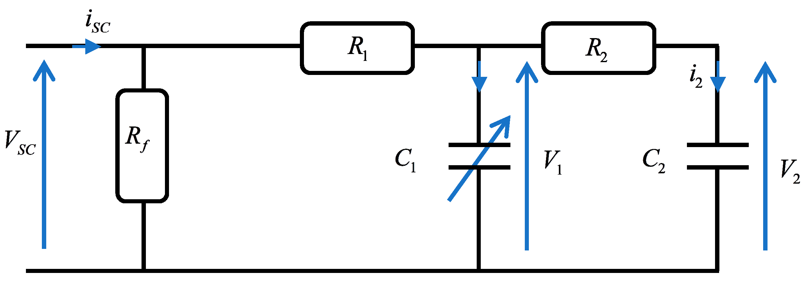
2.3. Supercapacitor Modelling

Supercapacitors (or electric double-layer capacitors, electrochemical double layer capacitors or ultra-capacitors) store the energy on two parallel plates isolated by an insulator [22]. It has a large capacitance, with capacitances of several thousand farads with energy density. In renewable energy technologies, particularly in photovoltaic power systems, the combination of supercapacitor and battery generated an outstanding match which will accommodate a wide variety of renewable energy and energy demands [23]. The supercapacitor is used to reduce and absorb the peak current in the battery when the irradiance is very highly fluctuated [24]. Figure 4 presents the supercapacitor simplified circuit with two-branch model [40]. It has two sections, the first of which is labelled fundamental, in which the energy is accumulated rapidly in a few seconds, and corresponds to a distributed constant model’s first R1C1 cells, and Rf presents the leakage current.
C1 is the main capacitance or differential which depends on the voltage V1 and contain C0 and Cv which represents the constant capacity and parameters, respectively, and is given as:
C 1 = C 0 + C V . V 1
The current and voltage characteristics of the corresponding electrical circuit of the supercapacitor are presented by the following equation, through ignoring the leakage current:
U S C = N S s c V S C = N S s c ( V 1 + R 1 I S C N P s c )
where USC and ISC are the supercapacitor pack voltage and current, respectively, Vsc is the elementary supercapacitor voltage. NPsc and NSsc are the numbers of parallel and series branches of the supercapacitor connections, respectively.
The voltage V2 is presented as:
V 2 = 1 C 2 i 2 d t = 1 C 2 1 R 2 ( V 1 V 2 ) d t
The current through the main capacitor is given in function of the instantaneous charge Q1 in the following equation:
i 1 = d Q 1 d t = ( C 0 + C V . V 1 ) d V 1 d t
The charge Q1 is determined from Equation (13) and then the voltage V1, the two equations being given as:
{ Q 1 = C 0 . V 1 + 1 2 C v . V 1 2 V 1 = C 0 + C 0 2 + 2 C V Q 1 C V

3. Operation Point Optimization

The control management of the hybrid system is meant to control the photovoltaic panels, battery, and supercapacitor. The energy generated by the photovoltaic module mainly depends on weather conditions, which introduce several problems in the power transformed to the load. According to various research papers and experimental studies, the photovoltaic module has a single maximum point [41]. Two algorithms, P&O and INC, are modified and used to ensure that the photovoltaic generator provides the maximum of power to the load. Battery storage was designed under conditions where the loading power approaches the photovoltaic system’s producing power. In addition, the multi-loop PI controllers are used in the bidirectional converter to control the current of the battery and supercapacitor. In the DC-link side, the voltage is controlled and maintained to the reference voltage by three PI controllers.

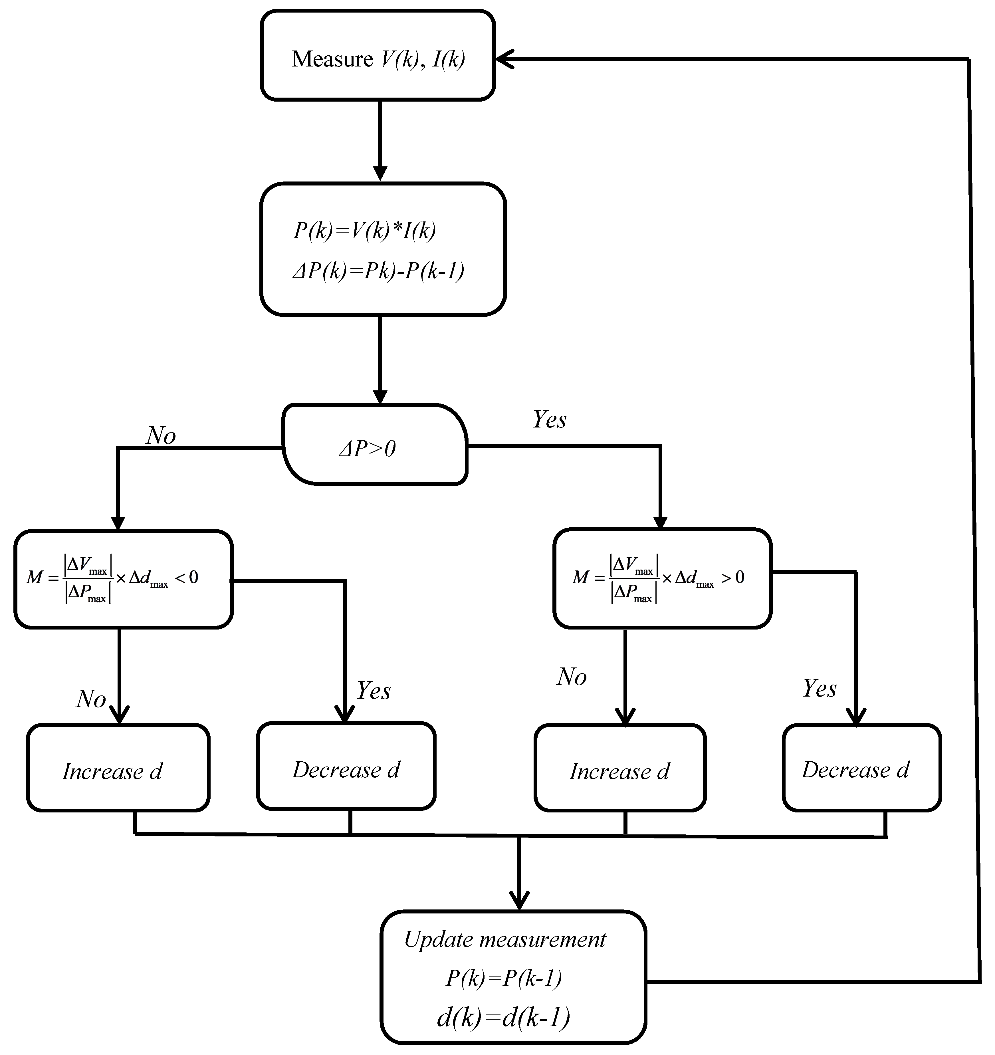
3.1. Perturb and Observe (P&O) Formulation

In this section, we propose the improvement of the P&O algorithm to track the maximum power from the photovoltaic array under varying solar irradiation. The P&O is the best and most widely used algorithm to track the MPP of the photovoltaic panel under varying dynamic conditions [9]. This algorithm is centered on their comparative perturbation parameter of voltage by ΔV based on the change of power (P) by the following rules [42].
{ V n e w = V o l d + Δ V × d P d V i f P > P o l d V n e w = V o l d Δ V × d P d V i f P < P o l d
The equation indicates the orientation of the perturbation, and the size of the ΔV is crucial to determine the convergence of the algorithm. The orientation of new perturbation depends on the value of the calculated power; if higher power is calculated at new voltage, the perturbation might go in the same direction, otherwise it will move in the opposite direction, as seen in Figure 5. The convergence speed depends highly on the perturbation sizes. In the high and low perturbation, the operating point oscillates around MPP and differs in the speed of convergence.
The operating voltage will be perturbed by small increment only if the operating point is far from the maximum power point of the photovoltaic array and then the change in ΔP is noticed. Generally, the steps of the P&O algorithm to finding the operating point can be summarized in four operations depending on the value of the perturbed voltage, as shown in Table 1 [42].
When ΔP is positive, it indicates that the operation point moves towards MPP, then, in order to drive it near MPP, the voltage will be perturbed in the same direction. Otherwise, when ΔP is negative, meaning that the MPP is far from the operating point and the voltage needs a perturbation in the reverse direction so as to move the operating point much nearer to the MPP.
In this paper, we use a small instantaneous perturbation step in the delta P&O algorithm in the slope dP/dV in order to modify the direction of the ΔP to be around the MPP. In delta P&O step, the duty cycle is perturbed to locate the operating point around to the MPP. The value dP/dV is used in order to evaluate the variable step size with scaling parameter, as given in the following equation:
d ( k + 1 ) = d ( k ) ± M | P ( k ) P ( k 1 ) | | V ( k ) V ( k 1 ) |
The parameter M is essential to decide the performance of the MPP system. It is necessary that M is automatically adjusted throughout the initialization process at start-up to maintain adequate operation under all initialization conditions. The Duty cycle dstart is configured to a small value for automatically adjusting parameter M. Eventually, the duty cycle is modified by adjusting the maximum safe step ∆dmax and the resulting values of generalized ∆Pmax and ∆Vmax are determined. The value of the parameter M is determined from Equation (17) and given as:
M = | Δ V max | | Δ P max | × Δ d max
The flowchart of P&O is presented in Figure 6.

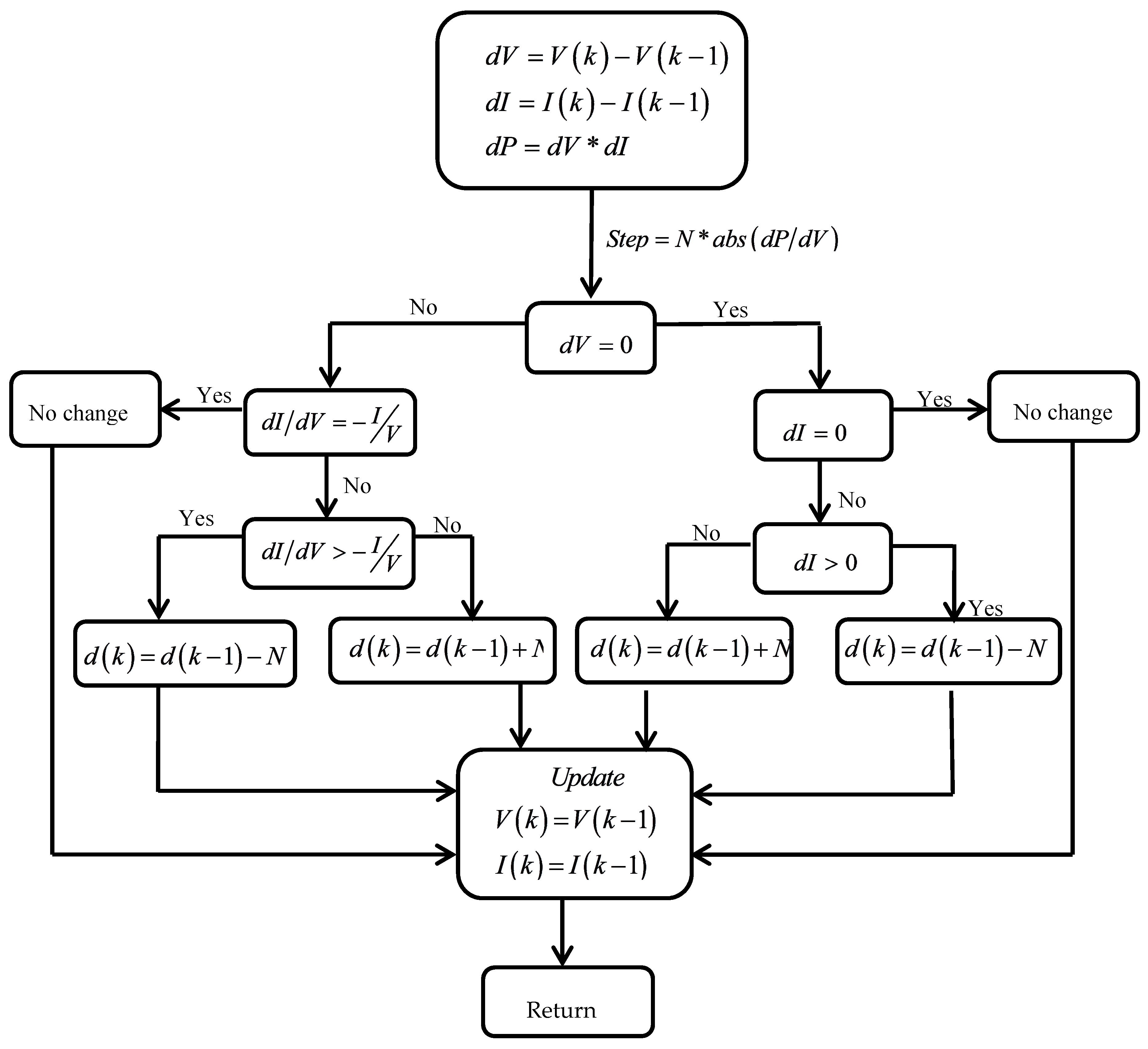
3.2. Incremental Conductance (INC) Formulation

The proposed technique in this section is using the INC algorithm to generate the maximum power from the photovoltaic array. The INC is an extension of the Hill-Climbing method, with the same principle of use and implementation as the P&O [27]. It is based on comparing the instantaneous conductance I/V and the incremental conductance dI/dV to identify the operation point of the photovoltaic in power–voltage curve, assuming that the incremental conductance at MPP is zero [28]. INC controls and tracks the maximum power rapidly under dynamic change in the solar irradiation or temperature. From the power–voltage curve of the photovoltaic, the INC tracks the operating point when the dP/dV is zero. The direction of the operating point depends on the value of dI/dV, as given in the following equation:
d I d V = I V
In the varying solar irradiation, the operating point needs to be controlled by a powerful algorithm. However, the INC can be modified depending on the situation and working conditions of the photovoltaic array. A step size is used in the INC algorithm, as proposed in [27], which is able to increase the tracking speed of the operating point in order to move around the MPP. Equation (20) presents the used variable step size adopted to track the MPP, where N is the scaling factor.
d ( k ) = d ( k 1 ) ± N × | d P d V |
The parameter N is essential to determine the performance of the MPP of the photovoltaic array. According to several research papers, a high value of ∆dmax is chosen for fixed step size in an attempt to ensure the convergences of the algorithm [43]. Around MPP, the value of the dP/dV is the lowest. In order to ensure the fast convergence of the MPP, the parameter N of variable step rule must obey the following:
Δ d max > N × | d P d V | f i x e d s t e p = Δ d max
where dP/dV at fixed step ∆dmax is the dP|/|dV| at fixed step size operation of ∆dmax, and the scaling factor N is given as:
N < Δ d max / | d P d V | f i x e d s t e p = Δ d max
The flowchart of the INC is illustrated in Figure 7.

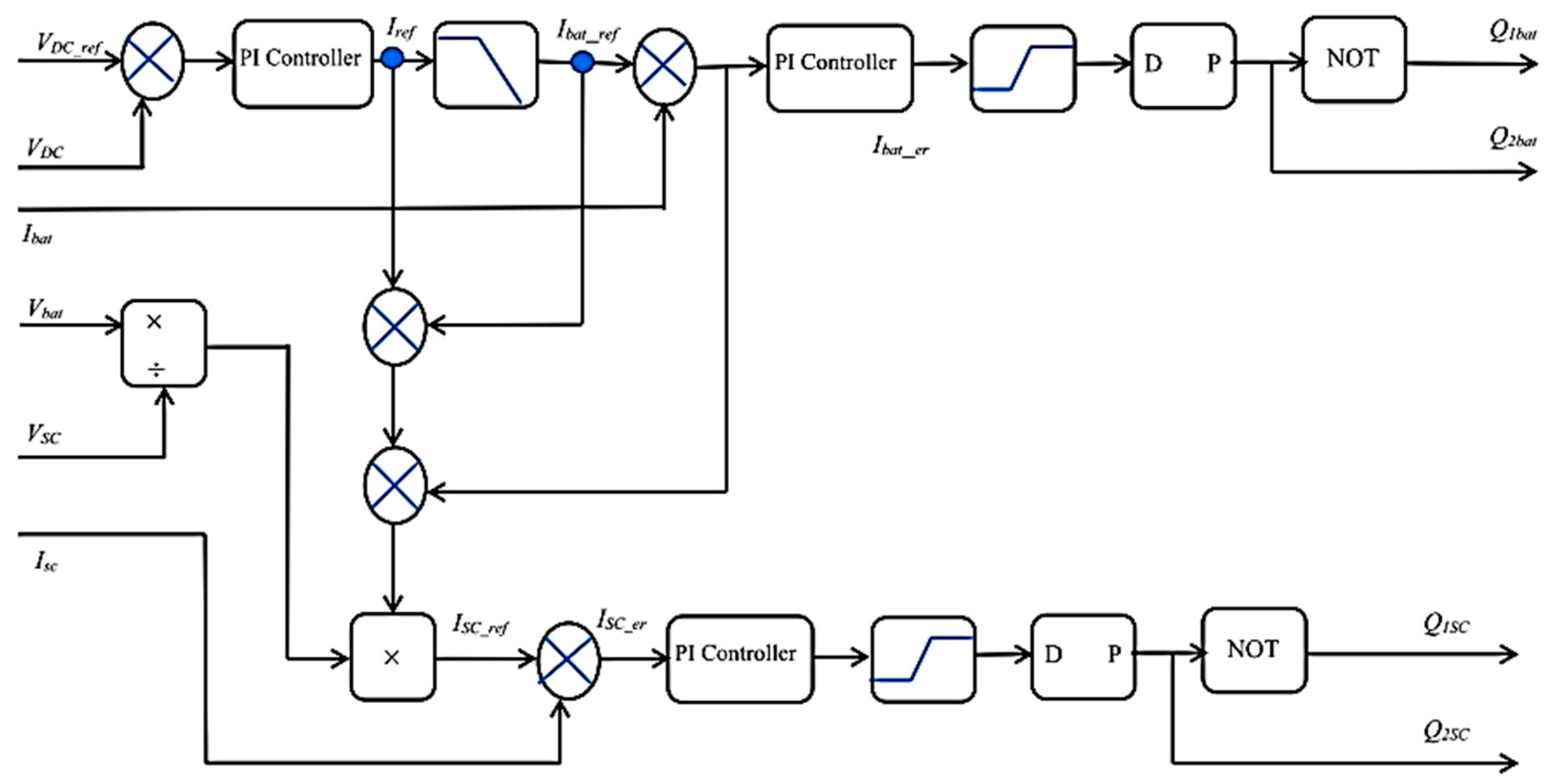
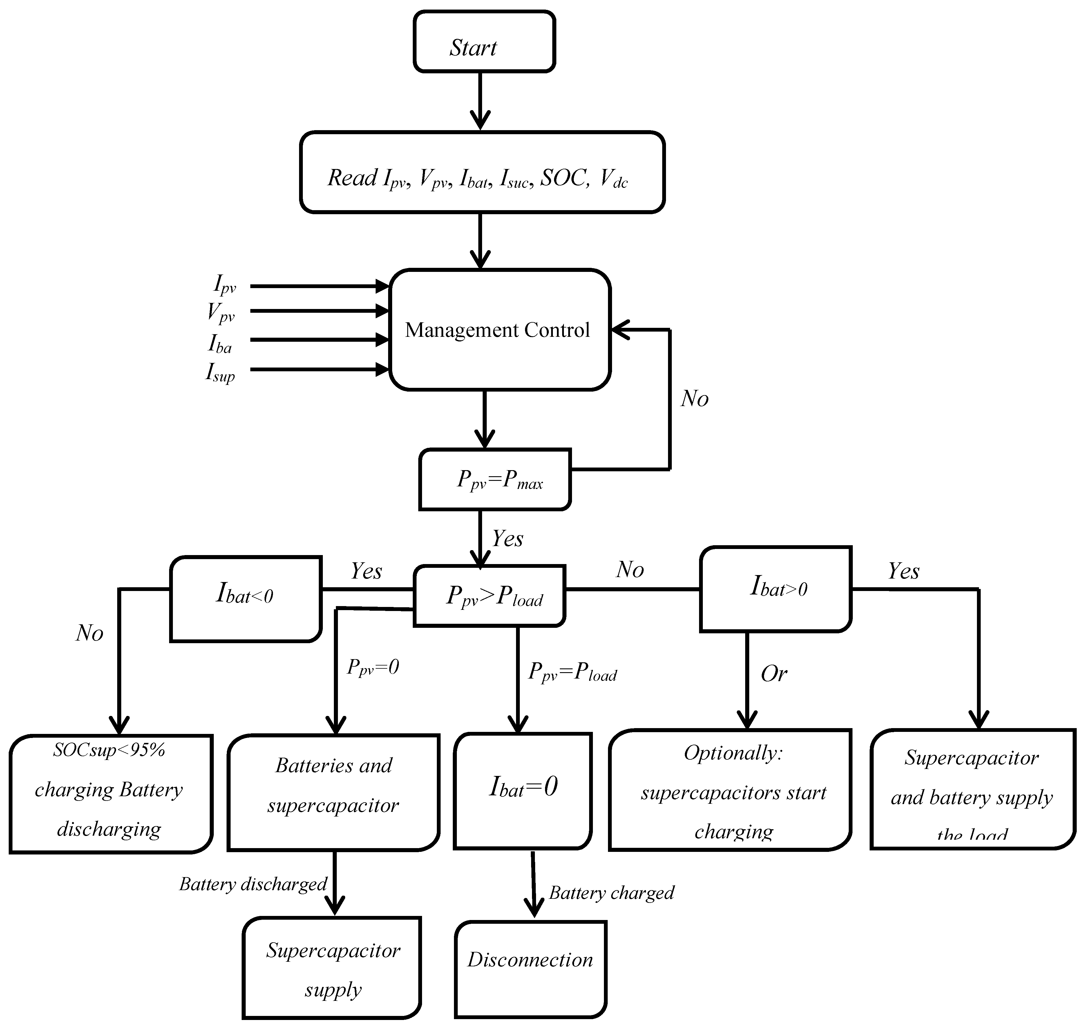
3.3. Control and Management of Storage System

This section is dedicated to controlling DC-link voltage, and current of the battery and supercapacitor, respectively. DC-link voltage is commonly included as a balancing power indicator for DC microgrids. Droop control method is the standard technique to managing the common DC-link voltage to the desired value. The DC-link voltage in controlled dynamic load depends on the power absorbed by the load and given as Pload = VDC-link.Iload. However, for controlling the overall system, a multi-loop PI control was designed, which consists of a first current loop and second voltage loop corresponding to the battery, supercapacitor, and to the DC voltage of the load. The first PI loop most the DC voltage loop set the VDC-ref corresponding to the load input DC link voltage. The second loop sets the Ibat-ref and Isc-ref for the faster inner PI loop which finally controls the current of the battery and supercapacitor and the DC link voltage with respect to the references. Generally, the controller has been structured in this segment in order to achieve the following control strategic objectives:
  • Balancing the voltage of the DC link voltage to the appropriate value,
  • Controlling the battery and supercapacitor currents to their corresponding values,
  • Maintaining global system stabilization.
The main control aim is to manage the voltage of the DC bus to its required value. The multi-loop PI controller estimates the reference current Idcref at the designated voltage Vref to maintain the DC-link voltage. This control technique regulates the transfer of the energy between the hybrid system and DC-link. In addition, the multi-loop PI controller regulates the energy between the supercapacitor and the DC-link and between the DC-link and the battery by employing a switch attached to them. It also decides when to deliver energy to the load, or when to charge the battery and supercapacitor.
Figure 8 presents the block diagram of the used control strategy in the DC-link. The DC-link voltage Vdc-link is correlated to the voltage Vref and the error is given to the multi-loop PI controller. The multi-loop PI controller determines the required cumulative current Iref from the microgrid.
The DC-link voltage can be modelled by:
C d c d V D C d t = I s c + I b a t + I P V I l o a d
Both currents of the battery Ibat and supercapacitor Isc are delivered by a multi-loop PI controller. These currents guarantee DC-link voltage permanence irrespectively of the load behavior and the nature of the power generated from the photovoltaic array. When a problem occurs on an element, the batteries and/or supercapacitors maintain that the DC-link voltage is controlled. Figure 9 presents the multi-loop control of the battery and supercapacitor.
Generally, and by definition, the charging and discharging mode mainly depends on the reference storage current. The battery is charging if the reference current is positive and discharging if it is negative. Figure 10 describes the functionality of the energy management strategy by supplying the batteries and supercapacitors with comparison currents for various charging conditions.
During the control, the DC-link voltage is compared to the DC voltage of the photovoltaic array, and then transformed to an external loop voltage PI controller to produce the error. The controller minimizes the error to generate the current reference Iref. The reference current should be regulated by the operation of battery current regulating to the maximum appropriate charging and discharging currents [Ibatmin, Ibatmax]. The present limitations are based on the ratings of the batteries. The existing comparison is related to the real battery existing Ibat and the error can be adjusted again. On the other side, the supercapacitor is renowned for its higher power density and faster reaction.
The photovoltaic hybrid system has several possible modes of operation depending on the switches that are operated:
Mode 1: If the photovoltaic array provides energy more than requested, then the current of the battery is negative and the state of charge (SOC) of the supercapacitor is more than 95%. Otherwise, the SOC is less than 95%.
Mode 2: If the photovoltaic array cannot provide the requested energy, then the current of the battery is positive, and the SOC of the supercapacitor is less than 95%. Optionally, the supercapacitors start charging. The battery and the supercapacitor supply the needed energy to the load.
Mode 3: If the photovoltaic array generates and supplies exactly the requested energy to the load, then the received current of the battery bus must be equal to zero.
Mode 4: If the photovoltaic array does not supply any energy (at night or the photovoltaic disconnected by any fault shading), that means the batteries and supercapacitor supply the requested energy to the load.
Mode 5: If the photovoltaic array provides enough energy and the batteries are completely charged, the battery should be disconnected for their protection.
Mode 6: If the photovoltaic array does not generate any energy and the batteries are discharged, the supercapacitor supplies the load until discharging and then the load will be turned off.

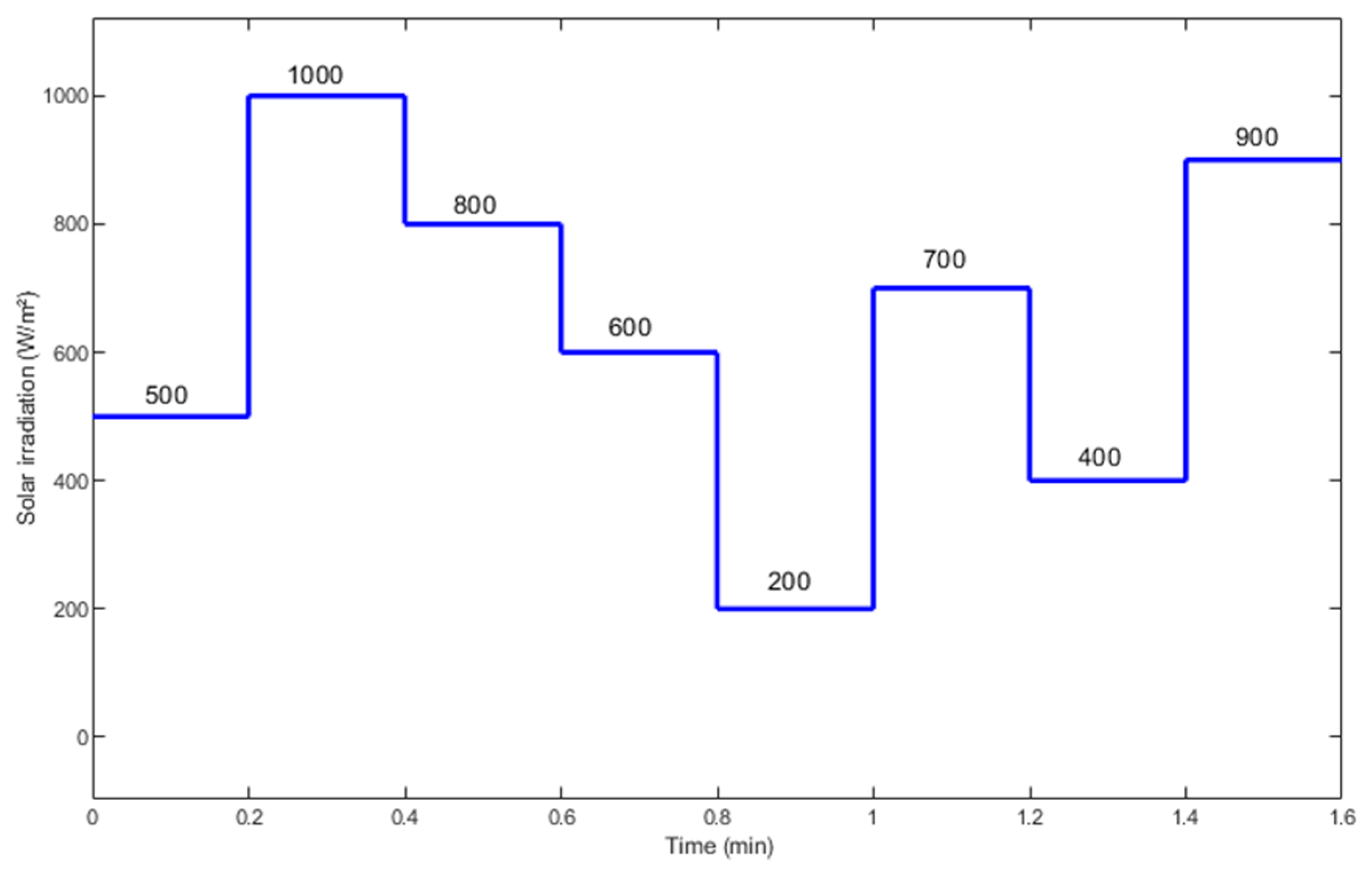
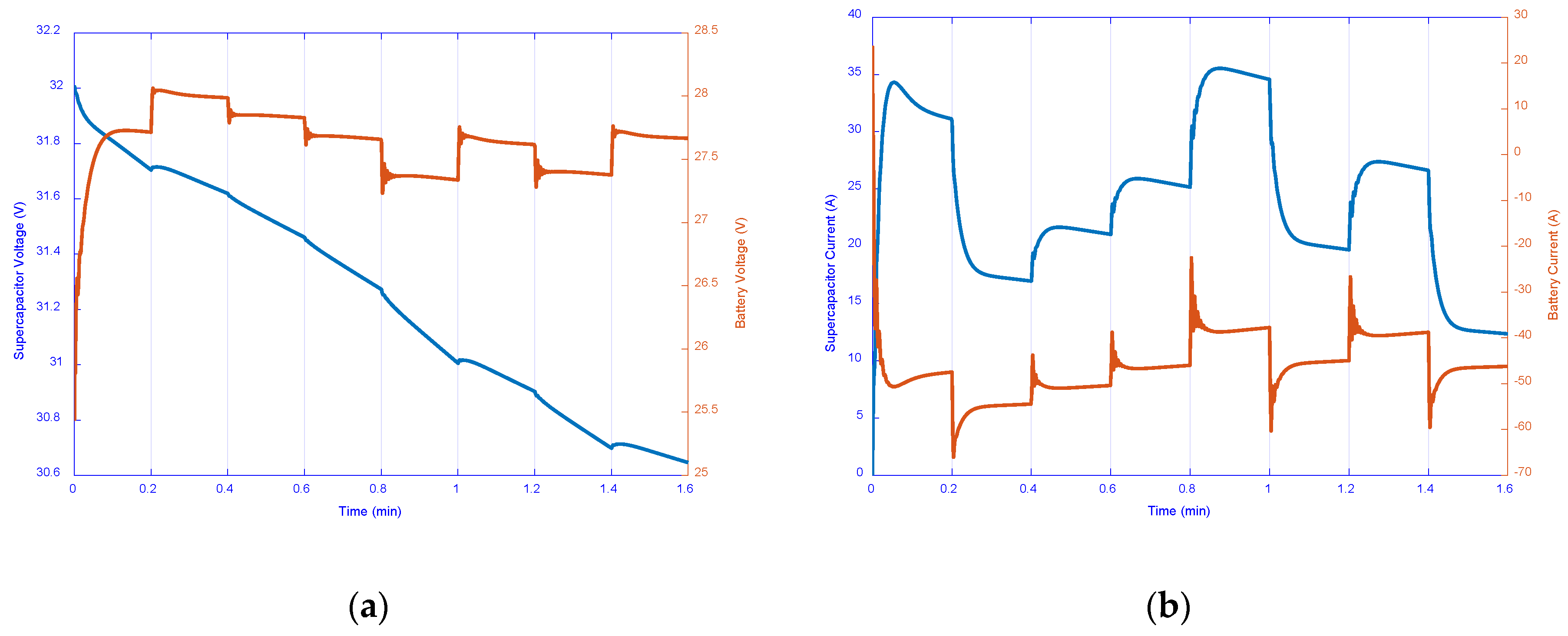
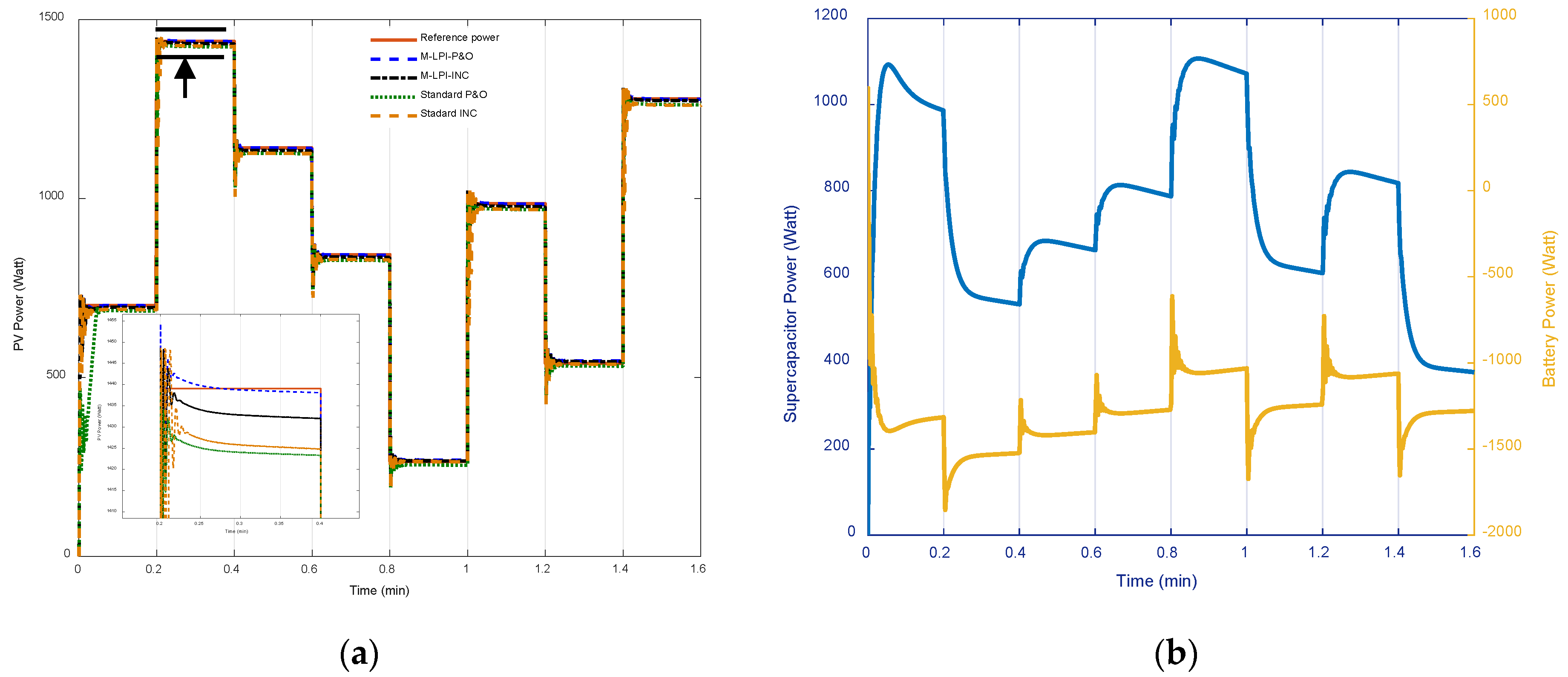
4. Simulation Results and Analysis

In order to evaluate the performance of the proposed hybrid storage system and validate the used algorithm and the multi-loop control, the simulation measurements are implemented for various solar irradiation and constant temperature in the MATLAB/Simulink.(2019a, MathWorks, Natick, MA, USA) The simulation is done using the Waaree Energies array, the battery and supercapacitor supposed charging at 50% and 100%, respectively, at the beginning of the simulation. In the proposed hybrid system, the lead–acid battery type is used and sized to supply the load in the absence of the sunlight radiation.
Figure 11 shows the solar irradiation received by the photovoltaic array during the simulation, each value of the solar irradiation being simulated for a step size 0.2 second from 0 seconds to 1.6 seconds. Further, the power production of the photovoltaic array mainly depends on the total solar irradiation received by the surface of the module and solar cells, meaning that any change in the power implies that solar irradiation changes. The change in solar irradiation during partially cloudy situations was found to cause a significant oscillation in system current, especially battery and supercapacitor current. This oscillation affects the lifetime of the storage system and can infect it by surcharge or a discharge in the photovoltaic.
Firstly, the photovoltaic is optimized to track the maximum power point using modified step size instantaneous P&O and INC algorithms compared to standard algorithms. Then the generated energy is injected in the boost converter and transformed to the load through the DC-link voltage. Figure 12 presents the comparison between the generated voltage and current from the photovoltaic array, using the modified P&O and INC algorithms. This current/voltage is transformed to the DC load through boost converter and DC-link voltage. A management control using the multi-loop PI controller is used to control the current of the battery and supercapacitor, while in the load side a voltage is controlled.
Figure 13 and Figure 14 present the variation of the voltage, current and power of the photovoltaic supercapacitor and battery, respectively. The first simulation starts at 500 W/m² solar irradiation and the supercapacitor is fully charged at 100%, while the battery is at 50%. The variation in the current, voltage and power (of the photovoltaic array, supercapacitor, and battery) are related to the solar irradiation variation, as given in Figure 11.
The negative energy in the battery indicated that the photovoltaic array generated enough energy to the load to charge the battery. This leads to say that the DC load is supplied only by the photovoltaic array and disconnected from the battery. During the battery charging, the voltage increases to its nominal value depending on the solar irradiation variation (Figure 13a). Given that the photovoltaic array generated enough energy, the control of the command module goes into power compensator mode which is explained by a negative current to protect the battery.
The generated energy from the renewable energy source is stable and shows a small fluctuation when the solar irradiation changes from one value to another only at the beginning. This fluctuation is eliminated by the supercapacitor discharge.
Figure 13a shows the evolution of the battery and supercapacitor voltage versus time. It is observed that the voltage of the supercapacitor drops from an initial value of 32 V to a final value of 30.6 V, while the voltage of the battery starts from 25.5 V to the final value of 28 V.
However, the battery and the supercapacitor power waveforms represented in Figure 14b show that the power delivered by the battery has transient peaks during all the backup time. Additionally, it is observed that the storage system charge and discharge follow the solar irradiation and depend on the injected energy by photovoltaic system. Furthermore, if the battery discharges, that means power is supplied to the load, then the supercapacitor discharges for the protection of the system and it absorbs the fluctuation.
The SOC of the supercapacitor and battery are presented in Figure 15. The supercapacitor discharges, and the battery immediately starts charging. The supercapacitor absorbs the fluctuation in the transformed energy to the load, when the battery supplies sufficient power to the DC load depending on its desired need. The SOC of the supercapacitor discharge is stopped at 95% and the battery more than 50%. That means the photovoltaic array is able to provide the requested energy from the solar irradiation to the DC load, and another part is stored in the battery for use when there is no solar irradiation or if the photovoltaic is not able to provide the desired energy.
In this work the photovoltaic array generates more energy than requested for the load, and thus the management control and distribution of the energy can be:
  • The photovoltaic panel supplies the load with Pload and the other power is stored in the battery as presented in Figure 15.
  • The discharge in the supercapacitor presented in Figure 15 is explained by the protection of the system and absorption of the fluctuation.
Figure 16 illustrates the provided and managed energy from the photovoltaic array, supercapacitor, and battery to the DC load. As shown in the modified P&O algorithm, it is better than the modified INC algorithm in terms of stability and eliminating the fluctuation. The hybrid system under instantaneous step size modified in the P&O algorithm generates more stable energy than the system which uses the INC algorithm. Moreover, the multi-loop PI controllers manage the elements current of the battery and supercapacitor and managed DC load voltage in the desired value.
The efficiency (ηpv) and the dynamic performance using the integral absolute error (IAE) are calculated using Equations (24) and (25) in order to evaluate the quality of the injected power by the photovoltaic array by the proposed algorithms.
η P V = 0 t P P V ( t ) d t 0 t P Re f ( t ) d t 100
I A E = 0 t | P P V ( t ) P Re f ( t ) | d t
Figure 17a illustrates the efficiency of the modified P&O and INC algorithms compared to the standard algorithms. Figure 17b presents the error in the power efficiency.
From Figure 17a, the efficiency of the photovoltaic is approximately 98% at 0.2 seconds and from 0.4 seconds it reaches more than 99% for the modified P&O algorithm. From the efficiency, it is clear that the photovoltaic array generated the maximum power from the solar irradiation. This energy is transformed to the load or stored at the storage system according to the need. Moreover, the dynamic performance of the instantaneous step size modified P&O algorithm is compared to the instantaneous step size modified INC algorithm using the integral error as shown in Figure 17b. The instantaneous step size modified P&O algorithm shows a lower error during the simulation time at different solar irradiation and better dynamic response. The standard and modified INC algorithm shows a high error at 200 W/m² and 400 W/m² (low solar irradiation) and low error at high irradiation, while the P&O algorithm shows a small error value for different solar irradiation. The P&O algorithm is the best algorithm to track the maximum power at dynamic change in weather conditions. However, the quality of the extracted energy from photovoltaic array plays a vital rule in the stability of the grid or any second load. The obtained simulation results for the proposed hybrid system demonstrate that the integration of the supercapacitor in the photovoltaic storage system leads to low rates of charge and discharge current of the battery (charge from 50% to 50.15%) and reduces the current stress levels on battery. This integration can protect the life cycle of the battery and absorbs the fluctuation in the injected energy and supplies the load as a second storage source if any fault has appeared.

5. Conclusions

Energy management and control of a battery and supercapacitor for a renewable energy source are presented. The photovoltaic array is optimized using two algorithms to track the maximum of the generated energy power, and the DC-link voltage is controlled to supply the DC load by the desired energy power. The planned HES is evaluated by simulation at constant temperature and under varying solar irradiation. The importance of using the storage system to manage the energy power transfer between the hybrid system and the load is discussed. The battery and supercapacitor are also utilized to absorb the fluctuation in the energy, provided by hybrid system to the load. The proposed two algorithms are modified by using the instantaneous step size in the voltage/current inductance, to reach the operation point when solar irradiation changes. The control management shows that when the battery charges, the supercapacitor discharges and vice versa. Therefore, the supercapacitor absorbs the fluctuation and protects the system when the battery discharges/supplies the load or when the load absorbs the energy. Moreover, when the battery charges, in turn the supercapacitor discharges, ensuring a protection of the system, and supplying the load to protect the lifetime of the battery.
The comparison of the results shows that the instantaneous step size P&O algorithm is better and provides more stable energy to the load without fluctuation, than instantaneous step size INC algorithm, and it is also better than the standard P&O and INC algorithms. The controlled and corrected energy from the storage system to the load is presented during the working photovoltaic array under varying solar irradiation. SOC characteristics of the supercapacitor and battery are illustrated to demonstrate the effectiveness of the controller. The simulation results prove the importance of the battery and the supercapacitor use for the photovoltaic array under different values of solar irradiation and prove the effectiveness of the proposed control and energy optimization management strategy. For high and low irradiance levels, the efficiency of the transformed energy from photovoltaic array achieves more than 99%.
The presented simulation results showed that the battery charges slowly from 50% to 50.15 while in parallel the supercapacitor discharges from 100% to 95%. Further, the modified P&O algorithms using the instantaneous step size optimize the power with error under 0.01 (approximately 0.005). The proposed hybrid system injects 200 watts to the load, which can be installed in the rural area for domestic applications or for other applications, such as telecommunication station antenna or water pumping system.

Author Contributions

Conceptualization, M.L.; methodology, M.L.; software, M.L.; validation, M.L., D.T.C. and P.A.C.; formal analysis, M.L., D.T.C. and P.A.C.; investigation, M.L., D.T.C. and P.A.C.; writing-original draft preparation, M.L.; writing-review and editing, M.L., D.T.C. and P.A.C; visualization, M.L., D.T.C. and P.A.C.; supervision, M.L., D.T.C. and P.A.C.; project administration, M.L., D.T.C. and P.A.C. All authors have read and agreed to the published version of the manuscript.

Funding

This research received no external funding.

Acknowledgments

The authors are highly acknowledging the “Agence Universitaire de la Francophonie”, and the first author is thankful to the Faculty of Electrical Engineering and Computer Science, Transilvania University of Brașov, Brașov, Romania, for support this work.

Conflicts of Interest

The authors declare no conflict of interest.

References

  1. Subramani, G.; Vigna, K.R.; Sanjeevikumar, P.; Jens, B.H.; Frede, B.; Leonowicz, Z.; Pawel, K. Techno-Economic Optimization of Grid-Connected Photovoltaic (PV) and Battery Systems Based on Maximum Demand Reduction (MDRed) Modelling in Malaysia. Energies 2019, 12, 3531. [Google Scholar] [CrossRef] [Green Version]
  2. Louzazni, M.; Khouya, A.; Amechnoue, K.; Gandelli, A.; Mussetta, M.; Crăciunescu, A. Metaheuristic Algorithm for Photovoltaic Parameters: Comparative Study and Prediction with a Firefly Algorithm. Appl. Sci. 2018, 8, 339. [Google Scholar] [CrossRef] [Green Version]
  3. Vyas, M.; Jain, M.; Pareek, K.; Garg, A. Multivariate optimization for maximum capacity of lead acid battery through Taguchi method. Measurement 2019, 148, 106904. [Google Scholar] [CrossRef]
  4. Jing, W.; Lai, C.H.; Wong, W.S.H.; Wong, M.L.D. A comprehensive study of battery-supercapacitor hybrid energy storage system for standalone PV power system in rural electrification. Appl. Energy 2018, 224, 340–356. [Google Scholar] [CrossRef]
  5. Jiang, L.L.; Srivatsan, R.; Maskell, D.L. Computational intelligence techniques for maximum power point tracking in PV systems: A review. Renew. Sustain. Energy Rev. 2018, 85, 14–45. [Google Scholar] [CrossRef]
  6. Mukerjee, A.K.; Dasgupta, N. DC power supply used as photovoltaic simulator for testing MPPT algorithms. Renew. Energy 2007, 32, 587–592. [Google Scholar] [CrossRef]
  7. Chantana, J.; Kawano, Y.; Kamei, A.; Minemoto, T. Description of degradation of output performance for photovoltaic modules by multiple regression analysis based on environmental factors. Optik (Stuttg) 2019, 179, 1063–1070. [Google Scholar] [CrossRef]
  8. Louzazni, M.; Khouya, A.; Al-Dahidi, S.; Mussetta, M.; Amechnoue, K. Analytical Optimization of Photovoltaic Output with Lagrange Multiplier Method. Optik (Stuttg) 2019, 199, 163379. [Google Scholar] [CrossRef]
  9. Nguyen, B.N.; Nguyen, V.T.; Duong, M.Q.; Le, K.H.; Nguyen, H.H.; Doan, A.T. Propose a MPPT Algorithm Based on Thevenin Equivalent Circuit for Improving Photovoltaic System Operation. Front. Energy Res. 2020, 8, 14. [Google Scholar] [CrossRef] [Green Version]
  10. Kumar, G.; Trivedi, M.B.; Panchal, A.K. Innovative and precise MPP estimation using P–V curve geometry for photovoltaics. Appl. Energy 2015, 138, 640–647. [Google Scholar] [CrossRef]
  11. Balato, M.; Petrarca, C. The Impact of Reconfiguration on the Energy Performance of the Distributed Maximum Power Point Tracking Approach in PV Plants. Energies 2020, 13, 1511. [Google Scholar] [CrossRef] [Green Version]
  12. Al-Gizi, A.; Al-Chlaihawi, S.; Louzazni, M.; Craciunescu, A. Genetically optimization of an asymmetrical fuzzy logic based photovoltaic maximum power point tracking controller. Adv. Electr. Comput. Eng. 2017, 17, 69–76. [Google Scholar] [CrossRef]
  13. Lazaroiu, G.C.; Longo, M.; Roscia, M.; Pagano, M. Comparative analysis of fixed and sun tracking low power PV systems considering energy consumption. Energy Convers. Manag. 2015, 92, 143–148. [Google Scholar] [CrossRef]
  14. Tchakounté, H.; Fapi, C.B.N.; Kamta, M.; Djalo, H.; Woafo, P. Experimental Assessment of a Smart Sun Tracking System Consumption for the Improvement of a Crystalline Silicon Photovoltaic Module Performance under Variable Weather Conditions. Appl. Sol. Energy 2019, 55, 385–396. [Google Scholar] [CrossRef]
  15. Sahin, F.E. Fisheye lens design for sun tracking cameras and photovoltaic energy systems. J. Photonics Energy 2018, 8. [Google Scholar] [CrossRef]
  16. Sahin, F.E.; Yılmaz, M. High Concentration Photovoltaics (HCPV) with Diffractive Secondary Optical Elements. Photonics 2019, 6, 68. [Google Scholar] [CrossRef] [Green Version]
  17. Ju, X.; Xu, C.; Hu, Y.; Han, X.; Wei, G.; Du, X. A review on the development of photovoltaic/concentrated solar power (PV-CSP) hybrid systems. Sol. Energy Mater. Sol. Cells 2017, 161, 305–327. [Google Scholar] [CrossRef]
  18. Ahmed, J.; Salam, Z. A Maximum Power Point Tracking (MPPT) for PV system using Cuckoo Search with partial shading capability. Appl. Energy 2014, 119, 118–130. [Google Scholar] [CrossRef]
  19. Chao, K.-H.; Lin, Y.-S.; Lai, U.-D. Improved particle swarm optimization for maximum power point tracking in photovoltaic module arrays. Appl. Energy 2015, 158, 609–618. [Google Scholar] [CrossRef]
  20. Mutarraf, M.U.; Terriche, Y.; Niazi, K.A.K.; Khan, F.; Vasquez, J.C.; Guerrero, J.M. Control of Hybrid Diesel/PV/Battery/Ultra-Capacitor Systems for Future Shipboard Microgrids. Energies 2019, 12, 3460. [Google Scholar] [CrossRef] [Green Version]
  21. Tofighi, A.; Kalantar, M. Power management of PV/battery hybrid power source via passivity-based control. Renew. Energy 2011, 36, 2440–2450. [Google Scholar] [CrossRef]
  22. Luta, D.N.; Raji, A.K. Optimal sizing of hybrid fuel cell-supercapacitor storage system for off-grid renewable applications. Energy 2019, 166, 530–540. [Google Scholar] [CrossRef]
  23. Cabrane, Z.; Ouassaid, M.; Maaroufi, M. Analysis and evaluation of battery-supercapacitor hybrid energy storage system for photovoltaic installation. Int. J. Hydrogen Energy 2016, 41, 20897–20907. [Google Scholar] [CrossRef]
  24. Nassef, A.M.; Fathy, A.; Rezk, H. An Effective Energy Management Strategy Based on Mine-Blast Optimization Technique Applied to Hybrid PEMFC/Supercapacitor/Batteries System. Energies 2019, 12, 3796. [Google Scholar] [CrossRef] [Green Version]
  25. Mendis, N.; Muttaqi, K.M.; Perera, S. Management of low- and high-frequency power components in demand-generation fluctuations of a DFIG-based wind-dominated RAPS system using hybrid energy storage. IEEE Trans. Ind. Appl. 2014, 50, 2258–2268. [Google Scholar] [CrossRef]
  26. Bambang, R.T.; Rohman, A.S.; Dronkers, C.J.; Ortega, R.; Sasongko, A. Energy management of fuel cell/battery/supercapacitor hybrid power sources using model predictive control. IEEE Trans. Ind. Inform. 2014, 10, 1992–2002. [Google Scholar] [CrossRef]
  27. Tey, K.S.; Mekhilef, S. Modified incremental conductance MPPT algorithm to mitigate inaccurate responses under fast-changing solar irradiation level. Sol. Energy 2014, 101, 333–342. [Google Scholar] [CrossRef]
  28. Li, C.; Chen, Y.; Zhou, D.; Liu, J.; Zeng, J. A High-Performance Adaptive Incremental Conductance MPPT Algorithm for Photovoltaic Systems. Energies 2016, 9, 288. [Google Scholar] [CrossRef] [Green Version]
  29. “Waaree Energies | WS-250 to WS-275 | Fiche Technique Panneau Solaire | Annuaire Panneau ENF”. Available online: https://fr.enfsolar.com/pv/panel-datasheet/crystalline/25814 (accessed on 17 April 2020).
  30. Louzazni, M.; Khouya, A.; Amechnoue, K.; Mussetta, M.; Crăciunescu, A. Comparison and evaluation of statistical criteria in the solar cell and photovoltaic module parameters’ extraction. Int. J. Ambient Energy 2018, 17, 1–13. [Google Scholar] [CrossRef]
  31. Cotfas, D.T.; Deaconu, A.M.; Cotfas, P.A. Application of successive discretization algorithm for determining photovoltaic cells parameters. Energy Convers. Manag. 2019, 196, 545–556. [Google Scholar] [CrossRef]
  32. Louzazni, M.; Craciunescu, A.; Dumitrache, A. Identification of Solar Cell Parameters with Firefly Algorithm. In Proceedings of the 2nd International Conference on Mathematics and Computers in Sciences and in Industry, Sliema, Malta, 3 March 2016. [Google Scholar] [CrossRef]
  33. Louzazni, M. An analytical mathematical modeling to extract the parameters of solar cell from implicit equation to explicit form. Appl. Sol. Energy 2015, 51, 165–171. [Google Scholar] [CrossRef]
  34. Rezaei, M.M.; Asadi, H. A Modified perturb-and-observe-based Maximum Power Point Tracking Technique for Photovoltaic Energy Conversion Systems. J. Control Autom. Electr. Syst. 2019, 30, 822–831. [Google Scholar] [CrossRef]
  35. Li, C.H.; Zhu, X.J.; Cao, G.Y.; Hu, W.Q.; Sui, S.; Hu, M.R. A maximum power point tracker for photovoltaic energy systems based on fuzzy neural networks. J. Zhejiang Univ. Sci. A 2009, 10, 263–270. [Google Scholar] [CrossRef]
  36. Wei, Z.; Leng, F.; He, Z.; Zhang, W.; Li, K. Online State of Charge and State of Health Estimation for a Lithium-Ion Battery Based on a Data–Model Fusion Method. Energies 2018, 11, 1810. [Google Scholar] [CrossRef] [Green Version]
  37. Meng, J.; Boukhnifer, M.; Diallo, D.; Wang, T. A New Cascaded Framework for Lithium-Ion Battery State and Parameter Estimation. Appl. Sci. 2020, 10, 1009. [Google Scholar] [CrossRef] [Green Version]
  38. Lin, X. Theoretical Analysis of Battery SOC Estimation Errors under Sensor Bias and Variance. IEEE Trans. Ind. Electron. 2018, 65, 7138–7148. [Google Scholar] [CrossRef]
  39. Chen, Z.; Fu, Y.; Mi, C.C. State of charge estimation of lithium-ion batteries in electric drive vehicles using extended Kalman filtering. IEEE Trans. Veh. Technol. 2013, 62, 1020–1030. [Google Scholar] [CrossRef]
  40. Gualous, H.; Bouquain, D.; Berthon, A.; Kauffmann, J.M. Experimental study of supercapacitor serial resistance and capacitance variations with temperature. J. Power Sources 2003, 123, 86–93. [Google Scholar] [CrossRef]
  41. Tiwari, G.N.; Dubey, S. Fundamentals of Photovoltaic Modules and Their Applications; Royal Society of Chemistry: Cambridge, UK, 2009. [Google Scholar] [CrossRef]
  42. Al-Gizi, A.; Louzazni, M.; Fadel, M.A.; Craciunescu, A. Critical constant illumination time in comparison of two photovoltaic maximum power point tracking algorithms. UPB Sci. Bull. Ser. C Electr. Eng. Comput. Sci. 2018, 80, 201–216. [Google Scholar]
  43. Liu, F.; Duan, S.; Liu, F.; Liu, B.; Kang, Y. A variable step size INC MPPT method for PV systems. IEEE Trans. Ind. Electron. 2008, 55, 2622–2628. [Google Scholar] [CrossRef] [Green Version]
Figure 1. Microgrid photovoltaic storage system configuration.
Energies 13 03043 g001
Figure 2. (a) Current-voltage and (b) power–voltage characteristics of photovoltaic module (Waaree Energies WU-120).
Energies 13 03043 g002
Figure 3. Battery equivalent circuit model with the double RC network.
Energies 13 03043 g003
Figure 4. Supercapacitor simplified circuit: two-branch model.
Energies 13 03043 g004
Figure 5. Operating point according to the sign of dP/dV.
Energies 13 03043 g005
Figure 6. Flowchart of perturb and observe (P&O) algorithm.
Energies 13 03043 g006
Figure 7. Flowchart of incremental conductance (INC) algorithm.
Energies 13 03043 g007
Figure 8. Schematic diagram of the proposed multi-loop proportional integral (PI) controller of VDC.
Energies 13 03043 g008
Figure 9. Schematic diagram representation of battery and supercapacitor multi-loop PI controller.
Energies 13 03043 g009
Figure 10. Overview in the energy management flowchart.
Energies 13 03043 g010
Figure 11. Solar irradiation.
Energies 13 03043 g011
Figure 12. Photovoltaic (a) voltage and (b) current.
Energies 13 03043 g012
Figure 13. (a) Voltage and (b) Current the supercapacitor and battery.
Energies 13 03043 g013
Figure 14. Generated power, (a) photovoltaic module, (b) Supercapacitor and Battery.
Energies 13 03043 g014
Figure 15. State of charge (SOC) of supercapacitor and battery.
Energies 13 03043 g015
Figure 16. Transformed energy to the DC load at different solar irradiation.
Energies 13 03043 g016
Figure 17. (a) Efficiency of the modified P&O and INC algorithm, (b) error.
Energies 13 03043 g017
Table 1. P&O techniques [42].
Old Perturbation VoltageSlope of PowerNew Perturbation
PositivePositivePositive
PositiveNegativeNegative
NegativePositiveNegative
NegativeNegativePositive

