Article

Evaluation of a Modified Equivalent Fuel-Consumption Minimization Strategy Considering Engine Start Frequency and Battery Parameters for a Plugin Hybrid Two-Wheeler

WMG, University of Warwick, Coventry CV4 7AL, UK
*
Author to whom correspondence should be addressed.
Energies 2020, 13(12), 3122; https://doi.org/10.3390/en13123122
Submission received: 27 April 2020 / Revised: 6 June 2020 / Accepted: 11 June 2020 / Published: 16 June 2020
(This article belongs to the Special Issue Alternative Energy Sources)

Abstract

:
An appropriate energy management strategy is essential to enhance the performance of hybrid electric vehicles. A novel modified equivalent fuel-consumption minimization strategy (ECMS) is developed considering the engine operating point deviation from the optimum operating line. This paper focuses on an all-inclusive evaluation of this modified ECMS with other state-of-art energy management strategies concerning battery ageing, engine switching along with fuel economy and charge sustenance. The simulation-based results of a hybrid two-wheeler concept are analysed, which shows that the modified ECMS offers the highest benefit compared to rule-based controllers concerning fuel economy and reduction in engine switching events. However, the improvement in fuel economy using modified ECMS has significant negative potential effects on critical battery parameters influencing battery ageing. The results are analysed and found consistent for two different drive cycles and three different powertrain component configurations. The results show a significant reduction in fuel consumption of up to 21.18% and a reduction in engine switching events of up to 55% with modified ECMS when compared with rule-based strategies. However, there is a significant increase in battery temperature by 31% and battery throughput by 378%, which plays a major role in accelerating battery ageing. This paper emphasizes the need to consider battery-ageing parameters along with other control objectives for a robust assessment of energy management strategies. This study helps in laying down a foundation for future improvements in energy management development and it also aids in establishing a basis for comparing energy management controllers.

1. Introduction

Concerns over climate change, constraints on energy resources, stringent regulations on emissions and poor energy efficiency are all pushing the transportation industry to focus more on alternative technologies, such as Hybrid Electric Vehicles (HEVs) [1]. Plugin HEVs (PHEVs) have become the prime focus in recent times. However, battery cost is one of the major hurdles in a PHEV to limit its prevalence in the automotive industry [2]. The key point in using the full potential of hybridization is by designing a proper supervisory control strategy, which manages the split of demanded power between energy sources in the most efficient and optimum way. One of the important aspects of PHEVs is to optimize the performance of the hybrid energy system by developing an intelligent battery ageing-conscious energy management strategy.
Studies [3,4,5] suggested that hybrid electric controllers can be divided into rule-based controllers and optimization-based controllers. Rule-based controllers are based on predefined rules based on experience, calibration and tuning of controllers for the desired output without prior knowledge of the trip [6,7]. Optimization controllers overcome the inherent rigidity of rule-based controllers by using the optimal control strategy that minimizes a cost function [8,9]. The most powerful optimal control used for optimization controller is equivalent fuel-consumption minimization strategy (ECMS) and it is generally accepted to be a promising real-time controller because of its feasibility and optimality [5,10,11]. In [12], Paganelli et al. have developed optimal control for a parallel hybrid and compared the fuel consumption with a rule-based conventional strategy; the fuel consumption reduced by 17.5% for the test cycle considered. Similarly, in [10,11,12,13,14,15], the authors C. Sun et al., J. Han et al., G. Paganelli et al., C. Musardo et al., L. Serrao et al. and L. Namwook et al. have implemented ECMS and compared the results of fuel consumption and charge sustainability with rule-based strategies. In all these references considered, ECMS shows significant improvement in fuel economy along with charge sustenance when compared to rule-based strategies. However, the control objectives in these references remained limited to fuel economy, tailpipe emissions and charge sustainability. The fuel economy of any type of HEV is highly dependent on the energy capacity of the on-board energy storage system [2]. Battery replacement cost is one of the critical factors to be explored in depth in PHEVs concerning energy management strategies. Therefore, it is very important to estimate the effect of energy management on battery health alongside with fuel economy and other control objectives. The assessment of energy management strategies should always include an exclusive study of all the powertrain components and their critical parameters. However, in the considered literature, there is no all-inclusive study exploring the connection or real tradeoff between battery ageing, engine switching and fuel economy.
Batteries are the most dominant choice of an energy storage system in road transport. Nonetheless, batteries experience an irreversible degradation processes while in use, which affects the energy capacity and the internal resistance of the storage system [9]. Battery capacity loss is due to many factors, which include various environmental and operating conditions. High C rate operation, a low or high state of charge (SOC), high battery temperature and the excessive depth of discharge are a few critical factors contributing to battery health degradation [16,17,18,19]. Batteries represent a large part of vehicle cost in a PHEV [2]. Hence, studying the effect of energy management on battery ageing is an important criterion to consider. In [20], the authors proposed a multiobjective optimal control problem, which considered both fuel consumption and battery ageing by converting the battery pack replacement cost to an equivalent fuel cost. However, the limitation of [20] is that they have not exclusively studied the effect of energy management on battery parameters influencing battery ageing: battery temperature, battery throughput and charge/discharge C rate.
HEVs have multiple power sources, and their fuel economy and emissions can be optimized by energy management strategy. As a result, under the influence of the energy management strategy, HEVs frequently make transitions between different pre-defined modes to achieve an optimal instantaneous power distribution. However, HEVs tend to suffer from issues such as drivability, starting system reliability and excessive clutch wear during mode transition [21,22]. Unlike four-wheelers, two-wheelers are an inherently unstable vehicle. The vehicle drivability and safety are linked to each other in two-wheelers, especially during the vehicle cornering phases [23]. Thus, it becomes even more important to develop an energy management strategy considering engine switching events along with battery ageing for a hybrid two-wheeler.
None of the references considered have done a stipulated comprehensive assessment of energy management strategies considering the battery ageing effects, engine switching events along with fuel economy. All the studies in the considered references were limited to fuel economy and tailpipe emissions. The evaluation and comparison of energy management strategies are incomplete without exclusively studying the effect of energy management strategies on all the critical battery parameters influencing battery degradation. This paper emphasizes the assessment of rule-based and optimal control-based strategies by thoroughly studying their effect on battery ageing parameters, engine switching events along with fuel economy and charge sustenance.
The four controllers considered for this study are:
(1)
The conventional Basic rule-based Energy Management Strategy (BEMS);
(2)
The Modified rule-based Energy Management Strategy (MEMS);
(3)
The conventional Equivalent fuel Consumption Minimization Strategy (ECMS);
(4)
The Modified ECMS named as ECMS_LL.
Apart from the conventional BEMS and ECMS, modified rule-based MEMS and Modified ECMS-ECMS_LL are considered for studying the effect these energy management strategies on fuel optimality, engine switching frequency and battery parameters. These modified energy management strategies improve the engine’s efficiency and thereby increase the fuel optimality by utilizing the electric path favourably over the conventional strategies BEMS and ECMS. However, the increased engine efficiency has a negative impact on battery parameters and this is one of the key focus of this study. The study is performed for two different drive cycles—Worldwide Motorcycle Test Cycle (WMTC) and Indian Drive Cycle (IDC) and three different vehicle configurations for the reliability of the results. Based on the respective simulation results, conclusions are drawn as to which directs a reciprocal relation between the battery parameters and the fuel economy in energy management.
The main contributions of this study are:
  • To design and develop a novel modified ECMS for a plugin hybrid concept two-wheeler, which enhances the fuel optimality further when compared to traditional ECMS.
  • Evaluation and assessment of modified ECMS with traditional ECMS and other rule-based strategies.
  • To perform an all-inclusive study and evaluation of energy management strategies considering battery parameters influencing battery ageing (battery temperature, battery Ah throughput, SOC and charge/discharge C rate), engine switching events and charge sustenance along with fuel economy.
This study helps in laying down a foundation for future improvements in energy management development and it also aids in establishing a basis for comparing energy management controllers.
The paper is organized as follows: In Section 2, the vehicle model of the full parallel two-wheeler HEV is explained. In Section 3, the HEV energy management control problem is formulated. In Section 4, the rule-based and optimal control-based controllers are designed and developed. Along with this, a novel modified ECMS (ECMS_LL) is developed and implemented. In Section 5, the simulation results of the controllers are investigated in detail for two different drive cycle and three different vehicle configurations. The results are analyzed and thereby the conclusions are discussed in Section 6 along with the future direction of the study.

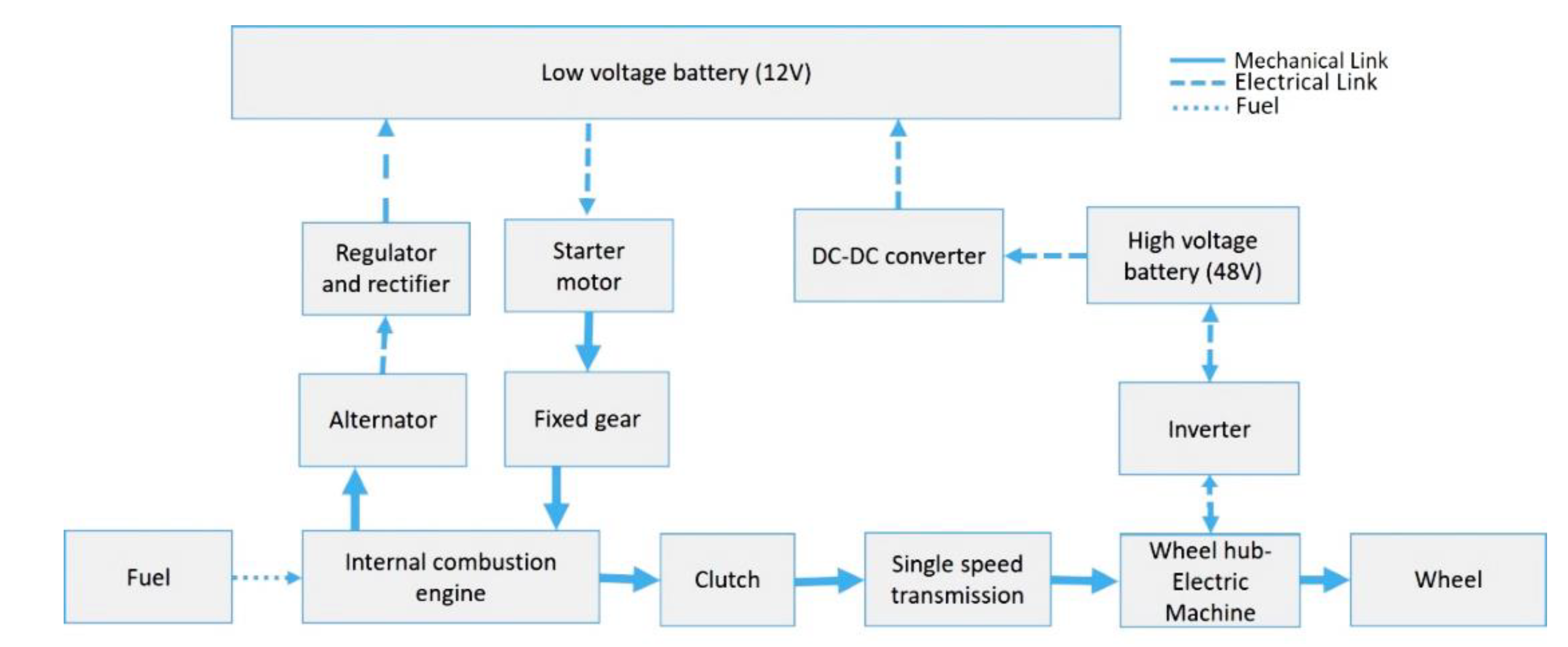
2. Vehicle Model and System Configuration

Two different approaches to HEV modelling can be adopted: backward or forward-facing modelling concerning the physical causality principles [24]. The former assumes that the vehicle meets the target performance so that the vehicle speed is known and the power request is calculated using the kinematical relationships imposed by the drivetrain. Forward-facing modelling takes, as inputs, the driver commands, and simulating the physical behaviours of each component generates the vehicle performance as an output. The powertrain data for the two-wheeler hybrid considered drives this study use a simplified appropriate backwards-facing model for this purpose [24,25]. A backward model developed by sourcing the detailed technical specifications and experimental data of engine, electric machine and battery from the hybrid two-wheeler concept is considered for this study. The power sources, transmission, and control system are developed using MATLAB/Simulink/State flow environment. Since the vehicle is a concept two-wheeler and not production-ready, the actual technical details of the powertrain components are not disclosed. In turn, the normalised values are displayed wherever necessary.

2.1. System Configuration

The vehicle considered for this study is a full parallel plugin hybrid concept two-wheeler and the powertrain architecture for the vehicle is as shown in Figure 1. The system is composed of an engine, a centrifugal clutch, an electric machine, mechanical transmission and an energy storage device (high voltage battery).
Figure 1 shows the mechanical and electrical power flow between the powertrain components. The electric machine is capable of power assist and charging from the engine along with pure electric drive depending on the wheel power requirement and the battery SOC. Hard constraints corresponding to the physical limits of the powertrain components are applied to the control input. The high voltage battery is used for vehicle propulsion and the low voltage battery is used for small dc loads and in starting the engine using a starter motor.

2.1.1. Vehicle Model

The plant model developed is a backwards-facing vehicle model. The longitudinal dynamics of the vehicle are described by [26]:
d V ( t ) d t = 1 m v . ( T w ( t ) r w 1 2 ρ a i r C d A V 2 ( t ) C r m v g )
where V denotes the vehicle speed; T w denotes the wheel torque; r w denotes the wheel radius; ρ a i r denotes the air density; C d denotes the aerodynamic drag coefficient; A denotes the frontal area of the vehicle; C r denotes the rolling friction coefficient; m v denotes the nominal weight; and g denotes the gravitational acceleration. The vehicle is assumed to operate on a flat road. Rolling resistance is considered as one single coefficient. The road material is taken to be hard asphalt (urban Indian roads), the absence of liquid, nominal tyre pressure, nominal tyre temperature and tyre material of rubber.

2.1.2. Engine

The engine model developed is established using steady-state maps based on experimental data from the hybrid two-wheeler concept vehicle. The model of the gasoline engine considered specifies the fuel consumption in (g/kWh) as a function of its operating point, defined by the engine speed (rad/s) and the engine torque (Nm). The engine’s fuel energy is used for charging the high and the low voltage batteries along with vehicle propulsion as shown in Figure 1.
The fuel flow rate m ˙ f of the engine is given by a steady-state map, which is a function of engine torque T i c e and engine speed ω i c e , i.e., m ˙ f = f ( ω i c e ,   T i c e ) .
The power consumption of the engine can be described by the following equation:
P f u e l   = Q l h v · m ˙ f
where Q l h v is the lower heating value of the fuel.

2.1.3. Electric Machine

The electric machine model is established using static maps derived from the experimental data. The efficiency of the electric machine η e m is given by a steady-state map, which is a function of both torque T e m and speed ω e m . Therefore, the power request of the electric machine is given by:
P e m = T e m · ω e m · η e m   ( T e m ,   ω e m )

2.1.4. Transmission

The transmission considered here is the single speed with constant efficiency of ‘0.90’. The clutch used here is centrifugal clutch and is modelled as a simple switch. Regenerative braking is not considered in this study as it can harm the stability of two-wheelers.

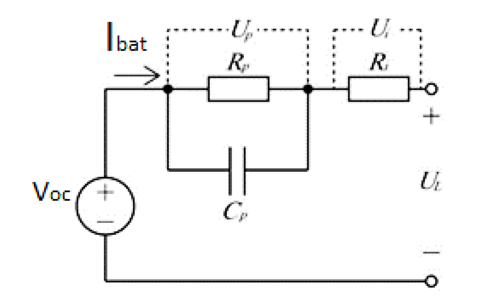
2.1.5. Battery Model

The battery is a non-linear system. The battery changes its properties based on many external and internal factors, such as ambient temperature, internal battery temperature, state of charge operation and the depth of discharge [9]. Electrochemical models for a Li-Ion battery as proposed by [27,28,29] are suitable for battery-level simulation. However, these models are not suitable for optimal control design because they involve a discontinuous mathematical function. Thus, a simple first-order equivalent circuit model is used for this study. Figure 2 shows the typical first-order equivalent circuit model of the battery. The battery can be represented as DC source VOC, RC network (Cp and Rp) and internal resistance Ri.
The battery internal resistance is a very important factor to calculate the SOC [30]. The battery internal resistance changes with SOC, battery cell temperature and battery ageing. In the battery model developed, the effect of SOC, C rate and battery cell temperature on internal cell resistance are considered [31].
The equation for calculating the battery current is as follows [32].
I b a t = V O C V O C 2 4 · R e q · P b a t 2 · R e q
where Ibat is the battery current, VOC is the open-circuit voltage, R e q is the equivalent battery resistance, and P b a t is the power in and out of the battery.
The Joule heating and the entropy effects are the major contributors for heat generation within the battery pack. For automobile applications, where C-rate of operation is high due to varying acceleration from the rider, the Joule heating effect dominates the entropy effect [33,34]. Hence, for the temperature prediction model, only heat generation due to the Joule heating effect is considered. The heat generation through the Joule heating effect is calculated using the relation Q = Ibat2Req, where Q is the heat generated, Ibat is the current and Req is the internal resistance. The battery is assumed to be a homogeneous body with uniform temperature distribution, the temperature difference between the core and the surface of the battery is not considered. The effect of ageing and state of health of the battery is not considered in this model.
A 3D lookup table is created based on experiments results [33], which computes the internal resistance of the battery at every time instant, based on instantaneous SOC, battery temperature, C-rate and the direction of the current flow. The resultant resistance is used in the model for the battery temperature rise calculation and as well for SOC calculation. The rise in the temperature calculated by equating the heat energy in joules against heat capacity equation: Q = MCΔT, where Q is the heat energy in joules; M is mass of the battery in kg; C is the specific heat capacity of the battery (J/kg °C); ΔT temperature rise in °C [33].
The battery considered in the study is air-cooled. A cooling study has been done on the same type of cells and has been found that cooling constant plays a major role while predicting temperature rise in cells during the vehicle run condition [33]. The average cooling rate °C/hour is calculated from the experiment results [31] conducted on the same cells and implemented in the battery Simulink model.
The powertrain model consisting of power train components are modelled using the experimental data from the hybrid concept two-wheeler. The engine maps, electric machine maps and battery model are based on the experimental data of the concept vehicle. Detailed technical specification of the powertrain components is restricted for publishing as the vehicle is a concept vehicle and is not production ready. However, the normalized data of the powertrain components are shared wherever necessary.

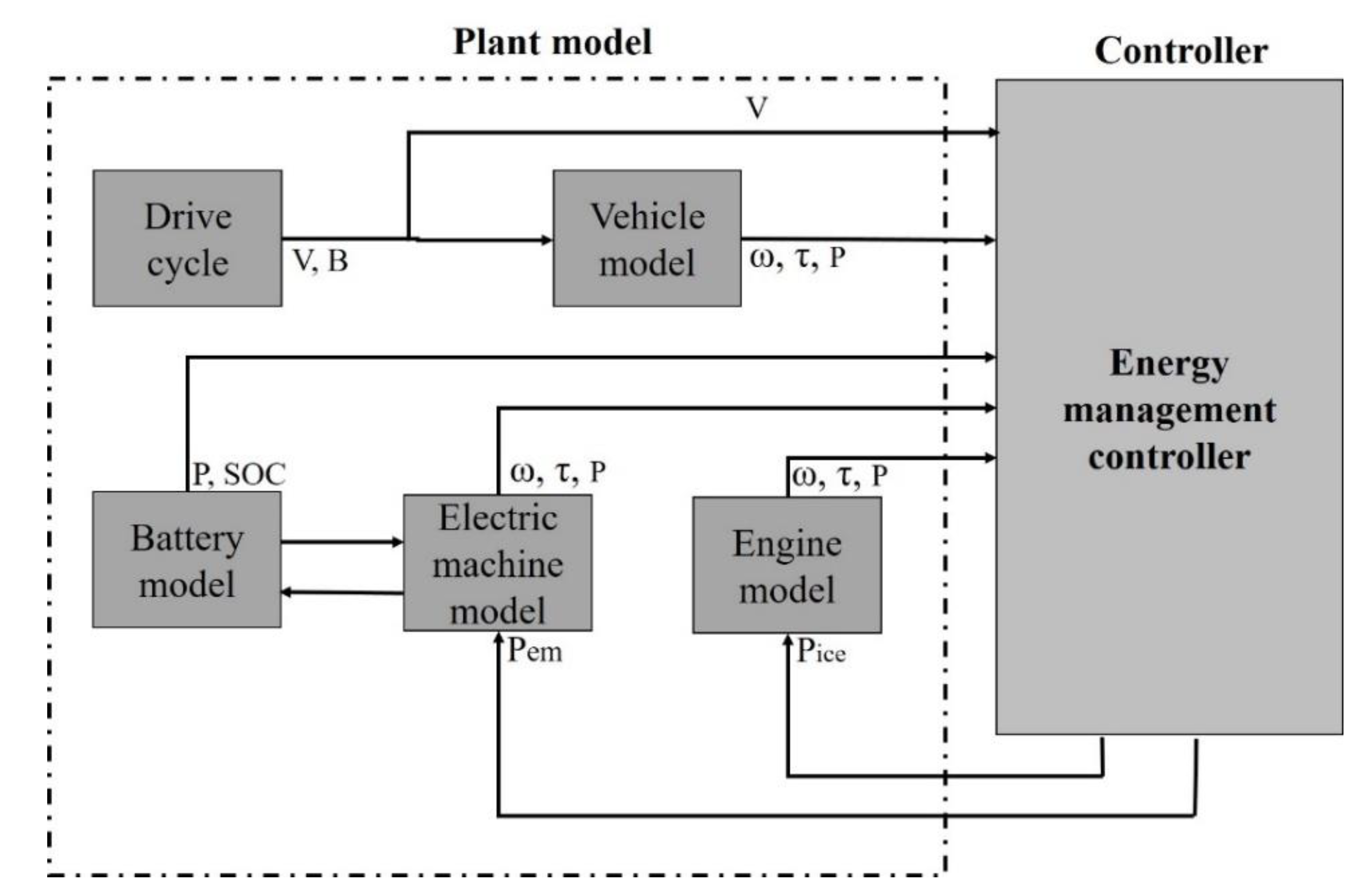
3. HEV Energy Management Control Formulation

For an HEV following a specific driving cycle, the system state equation can be described as [35]:
x ˙ ( t ) = f ( x , u , t ) = 1 Q b a t I b a t ( x , u , t )
where I b a t is denoted as battery current and Q b a t is denoted as battery charge capacity.
The control variable u ( t ) represents the control output, the power split between the engine fuel and battery. The optimal control problem to be solved by energy management is to minimize the following performance index [35]:
J ( u ) = 0 t f L ( u , t ) d t
The main optimization objective is to minimize the fuel consumption and therefore the instantaneous cost here is the fuel flow rate or the power equivalent to it [35]:
L ( u , t ) = P f u e l ( u , t ) = Q l h v m ˙ f ( u , t )
where Q l h v is the fuel energy density and is a constant.
This optimization problem is extended for a time interval [ 0 , t f ] constrained to various local and global constraints, which include:
Local constraints [35]:
u m i n ( t ) u ( t ) u m a x ( t )   t [ 0 , t f ]
1 u ( t ) + 1
where u ( t ) is the power split that ranges from ‘−1’ to ‘+1’. ‘−1’ means full regeneration by engine and vehicle traction power completely supported by engine, and ‘+1’ means full motor mode, the vehicle traction power is fully supported by the motor.
x m i n x ( t ) x max   t [ 0 , t f ]
where x ( t ) is the SOC, which has a minimum and maximum limit of charge-sustaining mode.
Global constraints [35]:
x ( t f ) = x f
x f is the final SOC target set for charge sustenance.
Initial conditions:
x ( 0 ) = x 0
x 0 is the initial SOC value set for the test.
x ˙ ( t ) = f ( x , u , t )

4. Energy Management Strategy Development

4.1. Energy Management Overview
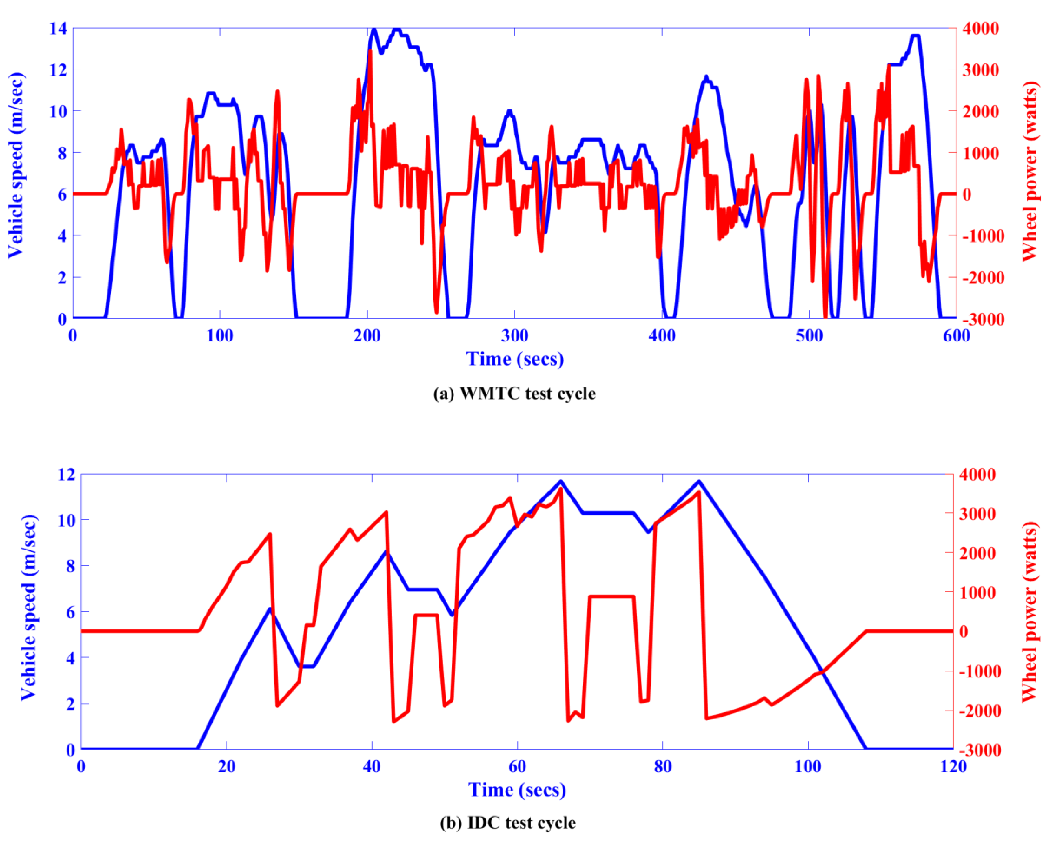
A supervisory energy management controller sets the power split between the electric machine and the internal combustion engine for all the input conditions.
Figure 3 shows the data flow between the energy management controller and the plant model, where P is the power, ω is the rotational speed; τ is the torque; V is the vehicle velocity and B is the brake information. The system constraints considered for the energy management controller are derived from the key powertrain components (engine—torque, power and speed; battery—power and SOC; electric machine—torque, power and speed). The power-split of (Pice and Pem) is the key control output.

4.2. Drive Cycles

For this study, two drive cycles are considered; Worldwide-Motorcycle Test Cycle (WMTC) [36] and an Indian Drive Cycle (IDC) [36], for testing and evaluating the consistency of the energy management control operation.
The WMTC is used as one of the reference drive cycles. This drive cycle is used for the small engine vehicle level tests in many countries (USA, Europe, China, and Japan). It replicates an urban drive cycle, with frequent acceleration, deceleration and start-stop conditions. The second drive cycle considered is IDC, which is a typical Indian urban drive cycle used for testing. According to UN-ECE regulation 168, for L category vehicle (with engine capacity < 150 cm3) with off-board charge capability, the legislative fuel economy test that considers WMTC is done in the following steps. The C O 2 is calculated as follows.
Condition A: Test with the fully charged electrical system. Condition B: Test with the fully discharged electrical system. Combining conditions A and B results in the following formula:
C O 2 ( g / km ) = ( E V R a n g e × C o n d i t i o n   A   C O 2 ) + ( D A V × C o n d i t i o n   B   C O 2 ) ( E V R a n g e + D A V )
where D A V is the distance between recharges: 4 km for L category vehicle and EVRange is the distance covered by the vehicle in electric-only mode from full charge to SOCLowlimit = 20% SOC.
The condition A test was simulated using the two-wheeler plant model, the simulation result shows the vehicle with fully charged battery takes around 4600 s (24 km), which is the EVRange and D AV : the distance between recharges considered is 4 km (from the UN-ECE regulation). The total drive time considered for test cases is therefore 28 km, which corresponds to 5200 s of the drive cycle. For this study, the WMTC and IDC drive cycles are therefore extended to 1.4 h. (5200 s) with the repetition of the cycle. The velocity and wheel power data of WMTC and IDC for a single test cycle of 600 s and 120 s are shown in Figure 4a,b, respectively.

4.3. Engine Switching Event

Engine switching is an important criterion to analyze when it comes to two-wheelers. During the engine cranking phase, once the ignition key is turned to initiate an engine start event, electric power from the low voltage battery is applied to the starter motor terminals to activate the starter solenoid and energize the DC starter motor engage the gear to the flywheel and thereby the engine is started. Every time the starter is cycled, it is subjected to wear and tear resulting from metal-on-metal contact on the gears and heat build-up within the electronics. Extreme environmental conditions and extreme usage of starter motor can lead to rapid degradation of life of starting system. According to warranty data gathered from a conventional two-wheeler of similar vehicle specifications considered, starter motors are designed for 50,000 cycles (estimated to correspond 3 years of use). However, the life of the starter motor also depends on the ambient conditions, engine condition (crank time required), and the time between starts (heat build-up) [37]. For this study, it is assumed that the engine starts at the first crank and hence the number of engine start events is equal to the number of starter system cycles.
Every time the engine switches on, it consumes a certain amount of fuel and electric power. From the experimental data, the fuel required for a warm engine-start, including the fuel required to chargeback the low voltage battery, is considered. The number of engine switching events is taken as a metric for comparing the controllers and can be directly related to the starting system life.

4.4. Energy Management Objectives

The problem considered in this paper is the energy management for a full parallel plugin hybrid two-wheeler. The essence of HEV control is the instantaneous management of the power flow from the ICE and the EM. The HEV control strategy aims to minimize the vehicle fuel consumption whilst maintaining the SOC, and meeting the driver demand and respecting the component limitations. The optimization objective considered in this work is to minimize fuel consumption during a trip, and the constraints are:
(1)
Charge sustainability: the battery SOC should remain at the defined SOC target reference at the end of the trip.
(2)
The satisfaction of driver demand: at each instant, the total torque output of the powertrain should be equal to the driver’s demand.
(3)
Actuator limitations: at each instant, the output of each powertrain component (engine and electric machine) is within its maximum torque/power rating; similarly, the total battery power is within acceptable limits in both charge and discharge operation.
For the consistency in operation of energy management controllers, different drive cycles and vehicle configurations are considered. Thus, along with different drive cycles, WMTC and IDC, three different system configuration are considered, as shown in Table 1. Table 1 shows the three different vehicle configuration taken into consideration for this study. The engine sizing is taken based on the availability of the engine models available in the production shelf. The three values of uniformly distributed charge C rate values from a minimum limit of 1C to a maximum limit of 5C is considered for the study.

4.5. Basic Rule-Based Energy Management Strategy (BEMS)

The rule-based controllers (BEMS and MEMS) are static controllers and the operating point of the components; engine and electric machine are chosen using rule tables as shown in Table 2 to meet the requirements of the driver and other components (electrical loads and battery) based on prior experience and testing as it is typical for rule-based controllers [6]. This table is formulated based on the rule-based controller used in the hybrid concept two-wheeler. A basic rule-based control strategy (BEMS) implements heuristic knowledge to develop a set of event-triggered rules. This strategy is implemented using Matlab State Flow. The five states are described as launch, electric-only, engine-only, combined (electric and engine) and braking states.

4.6. Modified Rule-Based Energy Management Strategy (MEMS)

The second control strategy is MEMS, which uses Load-Levelling Control (LLC). In LLC, the Internal Combustion Engine (ICE) is operated as close as possible to a predetermined value known as the optimal operating point for every instant in time during the vehicle operation [4]. The engine Optimum Operating Line (OOL) is the curve that connects the minimum BSFC for each given power. In actual practice, it is difficult to operate on the optimum operating line as the operating points are based on the wheel torque demand. Therefore, the ICE is operated as much as possible in the optimum operating region near the optimum operating line. The resulting power difference between the ICE and vehicle demand is either used or contributed by an electric machine. The maximum contribution of the electric machine is limited by the state of charge of the battery and its torque and power limitations.

4.7. Optimal Control Solution

Equation (7), which is subjected to Equations (8)–(12), is reduced to the instantaneous minimization problem of the Hamiltonian function H [14]. The global optimal energy management control problem for an HEV is reduced to the instantaneous minimization problem of Hamilton function by Pontryagin’s minimum principle, which is explained in detail in the literature [14].
The Hamilton is written as [14]:
H ( x , u , t ) = P f u e l ( u , t ) λ ( t ) · 1 Q b a t I b a t ( x , u , t )
The term λ ( t ) can be decoupled as [35]:
λ ( t ) = E b a t s ( t ) = V o c , m a x Q b a t s ( t )
where E b a t is the battery total energy and s ( t ) is a dimensionless term. The Hamiltonian function can be further interpreted as equivalent power and the expression is as follows [35]:
H ( x , u , t ) = P f u e l ( u , t ) + s ( t ) · P b a t ( x , u , t )
where s(t) is called the equivalence factor, which is the weighting factor that transforms the battery power into equivalent fuel power. In charge sustaining, HEV is the ultimate energy is from the fuel. The battery charge and discharge are translated into equivalent fuel consumption. Equation (16) was derived from intuitive considerations on energy balance by Paganelli [26], which resulted in the Equivalent Consumption Minimization Strategy.

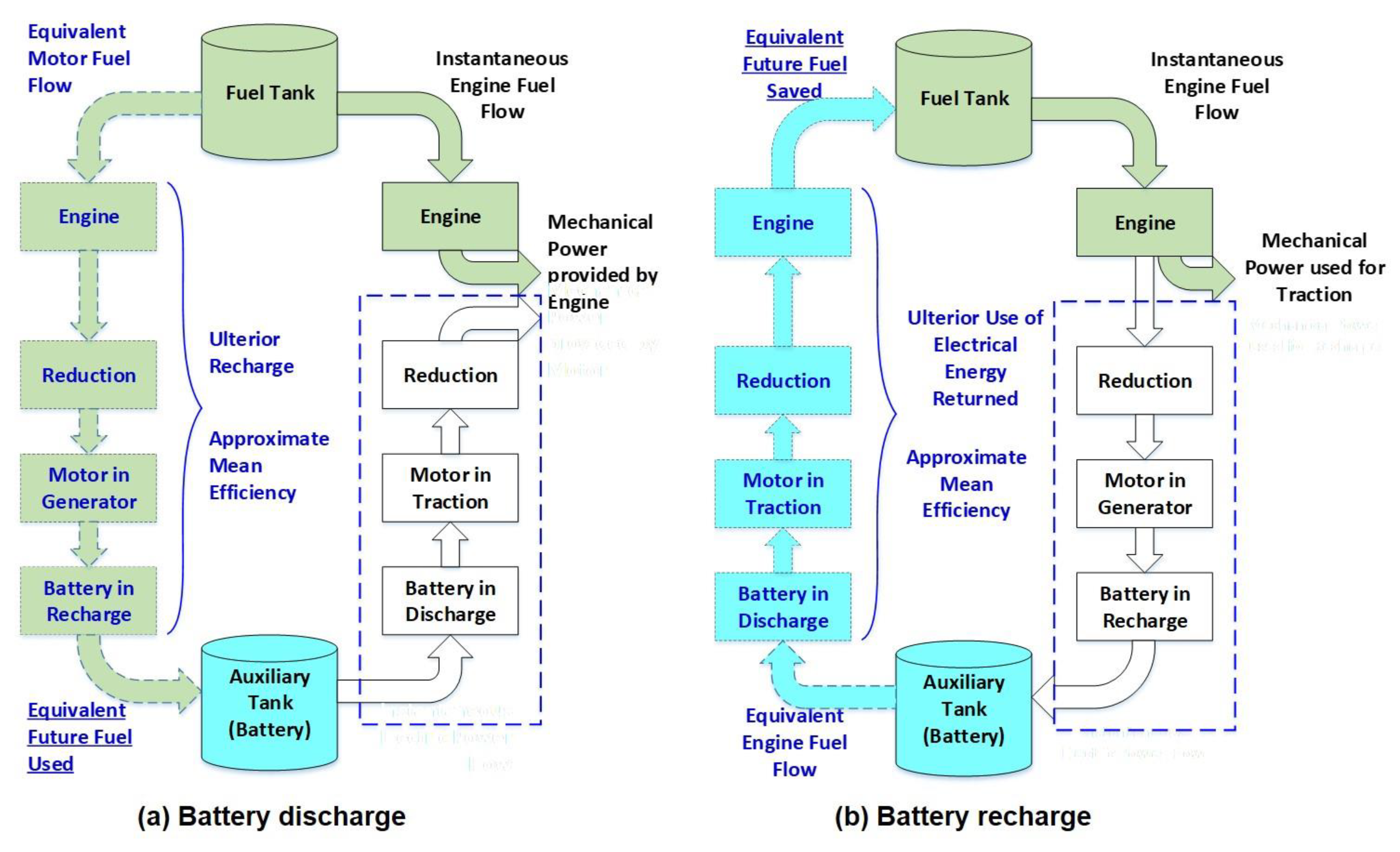
4.7.1. Equivalent Fuel-Consumption Minimization Strategy (ECMS)

The third strategy is based on the Equivalent fuel Consumption Minimization Strategy (ECMS), which is an instantaneous approach derived from Pontryagin’s Minimum Principle (PMP) [14,15,26]. It is well known that Pontryagin’s minimum principle can be applied to the HEV energy management problem to derive an optimal solution in the form of ECMS [38]. While heuristic control strategies such as BEMS and MEMS do not seek to optimize energy consumption or emissions, in contrast, the ECMS explicitly formulates a cost function for the equivalent fuel consumption to be optimized [12,13,35]. In a hybrid vehicle, a global optimization strategy usually sees the minimization of fuel consumption, or emissions, as the main goal. Paganelli [39] used an instantaneous optimization strategy to simplify the global optimization problem into a local optimization problem using minimum instantaneous equivalent fuel for each time cycle as an optimization objective. The instantaneous equivalent fuel consumption is equal to the engine’s instantaneous fuel consumption and the electric motor power that can be converted to fuel consumption [39]. ECMS was first proposed by Paganelli and applied to hybrid vehicle energy management strategies; to minimize the instantaneous fuel consumption, the concept of the equivalent factor was introduced [12].
ECMS sees the battery as an energy buffer, and all the energy consumption is equated to the engine’s fuel consumption. The battery can be viewed as a reversible energy conversion tank. For a particular parallel hybrid system, there can be two circumstances, which are as follows:
If the power of the battery is positive, as in discharging state, the battery is charged using extra fuel of the engine in future, as shown in Figure 5a.
If the power of the battery is negative, as in charging state, the battery energy is being stored, which can be utilized to reduce the load on the engine, thereby saving part of the fuel as shown in Figure 5b.
In both cases, the electric power is equated to fuel consumption in the future and the actual fuel consumption by the engine. The instantaneous fuel consumption can be calculated as follows [14]:
m ˙ e q v f u e l ( t ) = m ˙ I C E f u e l ( t ) + m ˙ B A T f u e l ( t ) = m ˙ I C E f u e l ( t ) + S Q l h v P B A T ( t )
where m ˙ e q v instantaneous equivalent fuel consumption m ˙ I C E is the instantaneous fuel consumption from the engine, m ˙ B A T is the instantaneous equivalent fuel consumption from the battery power (both in charging and discharging), s is the equivalence factor, which represents the conversion of electric power into fuel consumption and P B A T is the battery power, Q l h v is the low heating value of the fuel.
The cost function for equivalent fuel minimization is:
J ( x t , u t ) = m ˙ e q v f u e l ( t ) = ( m ˙ I C E f u e l ( t ) + m ˙ B A T f u e l ( t ) ) = ( m ˙ I C E f u e l ( t ) + s Q l h v P B A T ( t ) ) m i n
where control input u t [ 1.0 : 0.1 : 1.0 ] .
Subject to the following constraints:
P r e q ( t ) = P i c e ( t ) + P e m ( t ) S O C m i n < S O C ( t ) < S O C m a x     t   0 P i c e ( t ) P i c e , m a x ( t )   P e m , m i n ( t ) P e m ( t ) P e m , m a x ( t ) ω i c e , m i n ( t ) ω i c e ( t ) ω i c e , m a x ( t ) ω e m , m i n ( t ) ω e m ( t ) ω e m , m a x ( t )
ECMS strongly depends on the definition of the equivalence factor [39]. In the conventional ECMS formulation, the equivalence factor represents the chain of efficiencies through which fuel is transformed into electrical power and vice-versa, and it changes for each operating condition of the powertrain. The equivalence factor is tuned for both charging (schg) and discharging (sdchg) in charge-sustaining mode for a particular test cycle so that it minimizes the absolute fuel consumption for a given test cycle. The overall fuel consumption can be considered a function of the equivalence factors and a systematic optimization is used to find the equivalence factors that minimize the overall fuel consumption constrained to the SOC sustainability, i.e., final SOC equals pre-defined SOCref. The value of SOCref is taken as 0.30 in this study.
Along with the equivalence factor, to impose the SOC constraint, an SOC correction factor is used to shift the optimal power split up or down according to the difference between the actual state-of-charge and the target state-of-charge at every time instant. A non-linear ‘‘penalty function’’, p(SOC), as depicted in Figure 6 is used to represent the desired characteristics [39]. This function is used to sustain the charge about the SOC set point-SOCref. This is required avoiding the under or overcharging of the battery regardless of the vehicle demand.
The ECMS is only functional in the charge-sustaining mode where both power from the engine and electric machine is optimally split, to provide optimal fuel benefit with [26] minimum SOC deviation from the target. The equivalence factors schg and sdchg can be calculated as follows [14]:
S c h g = α 1 ( 1 β 1 ( S O C S O C r e f ) )
S d c h g = α 2 ( 1 + β 2 ( S O C S O C r e f ) )
α 1 > 0 , α 2 > 0
β 1 0 ,   β 2 0
S O C r e f = ( S O C H + S O C L 2 )
where α 1 and α 2 are the weighting factors (constant), β 1 and β 2 are penalty factors derived from the battery characteristics, S O C H   and   S O C L are higher and lower SOC limits and are calibrated based on the requirement, and S O C r e f is the target SOC, as shown in Figure 6.
The battery fuel component can be revised as follows [14]:
m ˙ B A T f u e l ( t ) = S c h g Q l h v P B A T ( t ) ,   f o r   I b a t 0
m ˙ B A T f u e l ( t ) = S d c h g Q l h v P B A T ( t ) ,   f o r   I b a t > 0

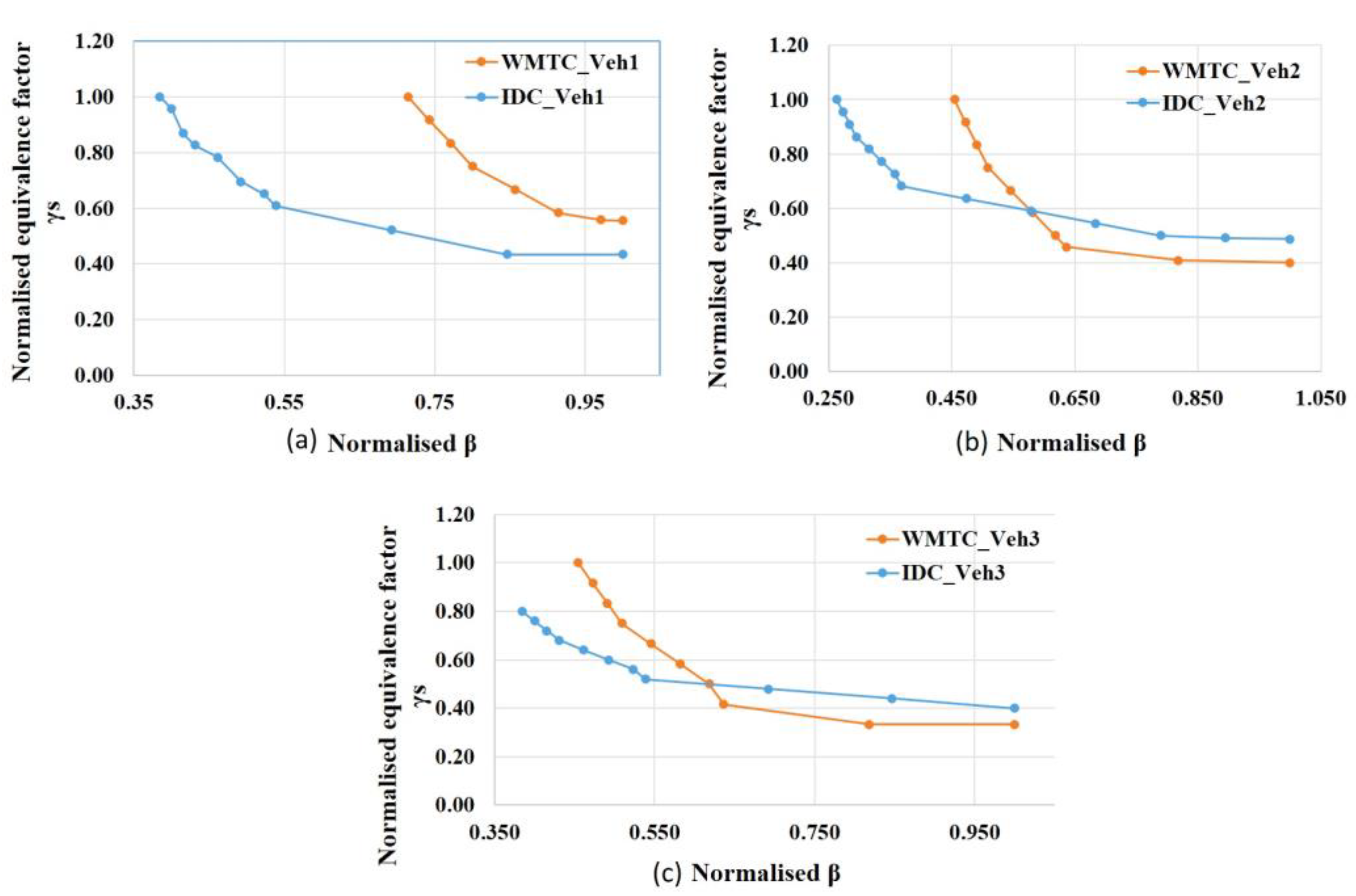
4.7.2. Proposed Equivalent Fuel Consumption Minimization Strategy (ECMS_LL)

The fourth controller, a modified conventional ECMS, is developed in this work and considered for the comparison. In the ECMS_LL, a new penalty function is introduced to the conventional ECMS control in the instantaneous cost function calculation. The original formulation of ECMS derived from impressive engineering intuition and was proved to work well, even without formal proof of optimality [32]. The derivation from the minimum principle includes a method, proposed and implemented in the earlier section, which introduces a penalty weight p(SOC) based on the deviation of SOC from the target SOC. This correction function adjusts the value of the equivalence factor when the SOC is close to its maximum or minimum acceptable levels to avoid the over-charging or over-discharging of the battery and thereby helps in the charge-sustaining approach. In fact, in the original ECMS formulation, the equivalence factor represents the chain of efficiencies through which fuel is transformed into electrical power and vice-versa, and it changes for each operating condition of the powertrain. The equivalence factor is considered an optimization variable that acts as a single tuning parameter for the required charge-sustained operation. This method improves the robustness of the strategy; however, it does not adopt the equivalence factor for exploiting engine to operate in the engine optimum region in most of its operational time throughout the drive cycle. The additional penalty function added to the cost function is the cost of engine optimum operating point deviation.
The penalty cost for the deviation from engine optimum operating point improves the optimality and increases the robustness of the strategy for a better fuel economy compared to the conventional ECMS. However, the inclusion of the new penalty factor does affect the equivalence factor tuned for conventional ECMS, which is tested and analyzed further.
The proposed modified ECMS attempts its maximum possibility to bring the engine operating points towards the engine optimum operating region by deriving a penalty function and implementing it into the cost function evaluation. The penalty function depends on engine operating points and its deviation from the engine optimum operating line at every time instant. The addition of this penalty function enhances the engine operating towards the engine optimum operating line, thereby improving the mean engine efficiency for the particular drive cycle considered.
J ( x t , u t ) = m ˙ e q v f u e l ( t ) = ( m ˙ I C E f u e l ( t ) + γ S Q l h v P B A T ( t ) + β ( I C E O P f u e l e f f I C E O O P f u e l e f f ( t ) ) ) m i n
where β ( I C E O P f u e l e f f I C E O O P f u e l e f f ( t ) ) is the new penalty cost function based on optimum operating point deviation. I C E O P f u e l e f f is the fuel efficiency of the engine operating point at that time instant, and I C E O O P f u e l e f f is the fuel efficiency of engine optimum operating point at that time instant. The addition of β ( I C E O P f u e l e f f I C E O O P f u e l e f f ( t ) ) affects the equivalence factor of conventional ECMS for the charge-sustained requirement and therefore a multiplier term γ is introduced in the function for the electric path. The value of the gain β is based on systematic testing for a particular drive cycle for charge-sustained SOC values. The main objective of the charge-sustained approach is to keep the SOC to the required reference value at the end of the trip. A range of β values is used and varied until the fuel benefit saturates under charge-sustained operation. For different β , the change in the equivalence factor ‘γs’ for the charge-sustained operation S O C r e f is calculated. Figure 7 shows the relationship between β and γs for WMTC and IDC for three different vehicle configurations considered.
Figure 7 shows the characteristic plot of the equivalence factor and the gain β of the new penalty function added to cost function for the minimization of fuel consumption. The characteristic plot is similar and consistent for different drive cycles and system configurations considered. By adding this penalty function, the mean engine efficiency for a particular drive cycle and system configuration can increase compared to the conventional ECMS. However, the percentage increase in the engine’s efficiency depends on the vehicle torque requirement (drive cycle dependent), different component sizing and charge C rate limits considered while formulating the control law.

5. Simulation Results and Discussion

An all-inclusive evaluation of rule-based and optimal based energy management strategies concerning battery ageing, engine switching, fuel economy along with charge sustenance is accomplished. To further check the reliability and consistency of the results, two different drive cycles (WMTC and IDC) and three different vehicle configuration (Veh 1, Veh 2 and Veh 3) are studied. All the cycles replicated to fulfil the distance of 28 km, which is defined as one-day driving. The simulation results of the optimization-based controllers (ECMS and ECMS_LL) are presented and compared with rule-based controllers (BEMS and MEMS).

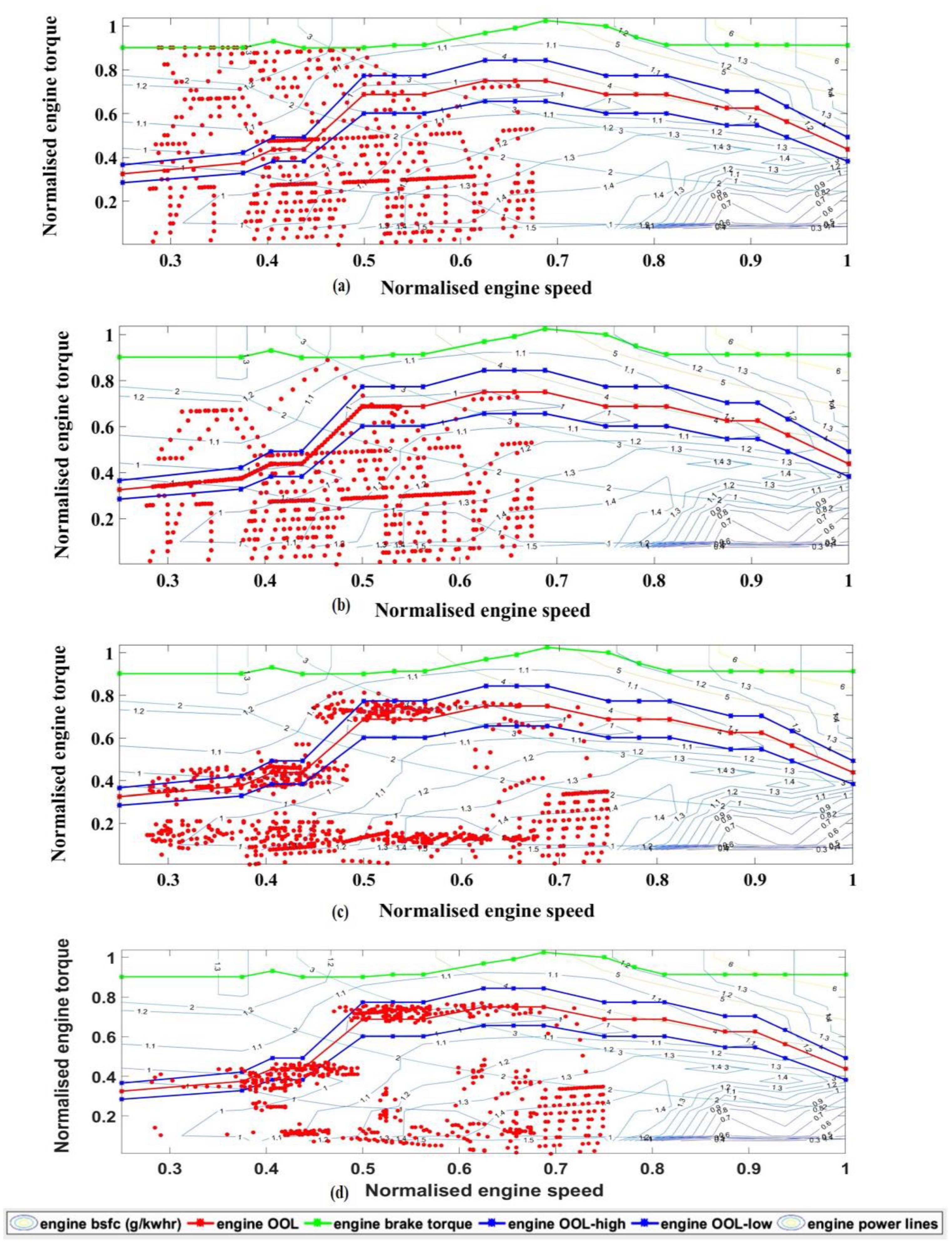
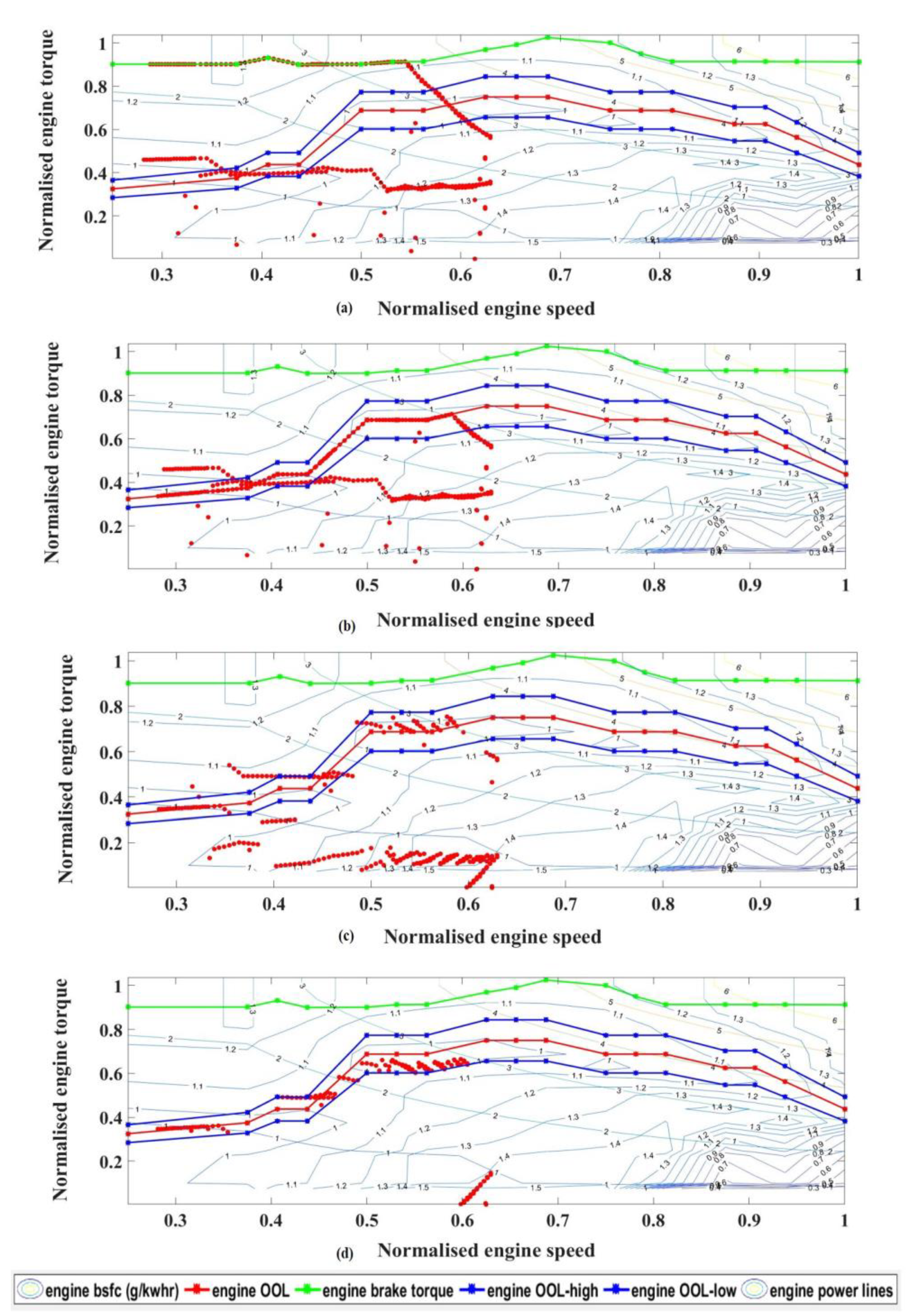
5.1. Engine Operating Points and Fuel Economy

Figure 8 and Figure 9 show the distribution of engine operating points for Veh 1 with BEMS, MEMS, ECMS and ECMS_LL controllers for the WMTC and IDC test cycles, respectively. From the figures, it is clear that irrespective of the drive cycles, the engine operating points clearly show that the engine efficiency is highest with ECMS_LL followed by ECMS, MEMS and BEMS. A similar trend is seen with Veh 2 and Veh 3 configurations. This is because the cost function calculated with optimal control ECMS and ECMS_LL is designed to minimize the fuel consumption at every time instant by choosing the best optimum power split. As discussed in the earlier session, ECMS_LL is designed by adding an extra penalty (based on the deviation of engine operating point from the engine optimum line) function to the cost function of ECMS, which improves the engine efficiency further and thereby fuel economy. When it comes to rule-based strategies and optimal control-based strategies, the latter is the clear winner when it comes to fuel economy. The optimal control strategies evaluate the best power split by prioritizing the ICE operating points near to OOL. This is done by using the resultant power difference between the ICE and vehicle demand being used or contributed by an electric machine and battery. This gives the optimal control strategies an advantage of better fuel economy, over the rule-based strategies. The rigid rules of the rule-based controllers constrain the possibility of the use of load levelling in certain conditions.
When implemented with optimal control, the ECMS_LL tries to choose the operating point that minimizes the total equivalent consumption by placing the engine operating point in and around the region of engine OOL. However, the ECMS has to select the engine operating point that has the minimum fuel consumption and yet satisfies the best SOC correction to display the necessary charge sustainability. Similar trends are observed with other vehicle configurations for WMTC and IDC drive cycles.
Table 3 shows the absolute fuel consumption (FC) and percentage FC reduction of the considered controllers. The fuel consumption improvement of optimal control ECMS and ECMS_LL over BEMS and MEMS is quite significant because of the engine operating in the best efficient regions. It shows consistent positive results with both drive cycle for all the three-vehicle configurations considered. A maximum fuel benefit of 21.18% is seen with ECMS_LL controller for vehicle configuration Veh 1 when tested for IDC drive cycle. A fuel benefit of 11.36% is seen with ECMS_LL controller for vehicle configuration Veh 1 when tested for WMTC drive cycle. The percentage of fuel benefit varies with drive cycle and vehicle configuration and the same is seen in Table 3. This is because of the engine sizing considered, charge C rate limits, wheel torque requirement from the drive cycles and other system constraints. However, they all show similar trends in fuel consumption reduction, with ECMS_LL displaying the highest benefit. The engine is made to operate near the optimum operating zone in most of the times by utilizing the electric path wherever applicable. Thus, here, the battery and electric machine are operated conveniently for increasing the engine’s efficiency.

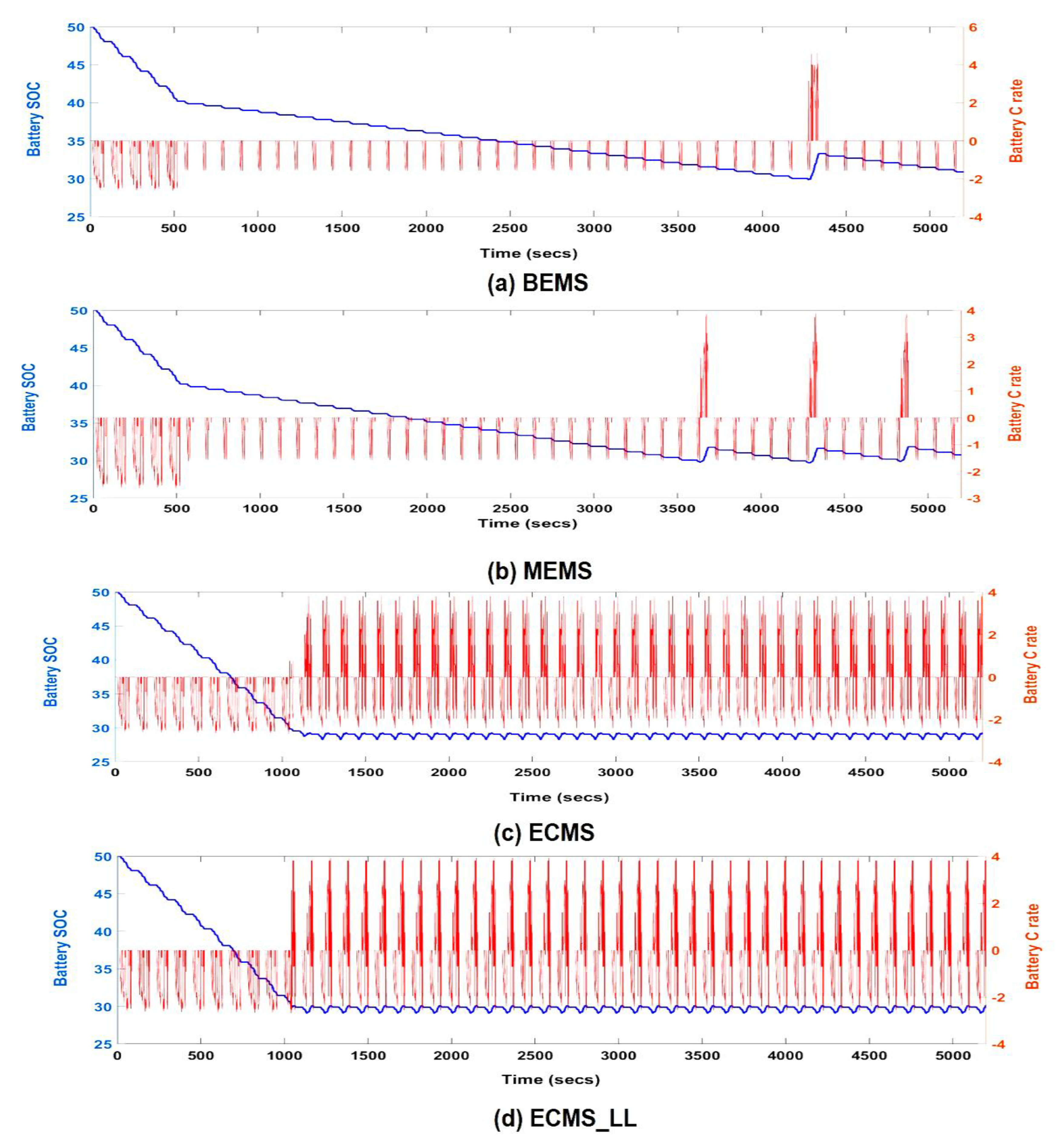
5.2. Charge Sustainability

One of the control objective considered during the formulation of energy management strategy is charge sustainability along with the minimization of fuel consumption. For a fair trade-off, the absolute fuel consumption is calculated by considering the equivalent fuel value of the difference of final SOC and final target SOCref (0.30). Table 4 shows the final SOC values for the controllers with WMTC and IDC test cycles for different vehicle configurations. The final SOC for the optimal controllers is within the stringent bandwidth of ±1% of the SOC target (SOC = 0.30) when compared to rule-based controllers. The optimal controllers ECMS and ECMS_LL satisfy the control objective of charge sustainability. In the case of rule-based strategies, the final SOC depends on the rules defined and varies with the vehicle power demand and torque requirement demand from test cycles considered. Nevertheless, the final SOC values with rule-based controllers achieve the SOC target like optimal controllers.

5.3. Engine Switching Events

Table 5 shows the engine switching events (ESE), for the considered controllers for different vehicle configurations and test cycles. With the rule-based controllers, the engine switching depends on the rules that are based on SOC limits considered and the drive cycle requirements for the wheel power and torque. It is seen that, with optimal control, the engine switching events consistently show lower numbers when compared to rule-based strategies. The engine-switching event is reduced by 23% and 55% for WMTC and IDC, respectively, using optimal control when compared to rule-based controllers. One of the important objectives of energy management control is to keep the rider comfort, safety and reliability of starting system in mind while evaluating the control strategies for a vehicle.
The starting system life of a typical conventional vehicle of a similar vehicle is 50,000 cycles/3 years. The one-day travel is defined as 28 Kms. If 50,000 cycles are distributed equally across 365 days/year, the per-day switching limit would be = (50,000/(3 × 365)) ~ approx. 46 switching events per day. Assuming that the engine switches in the first very cranking event, the number of engine switching events can be equated to the number of starting system cycles.
The optimal controllers fare better in reducing the engine switching events when compared to rule-based strategies. The rule-based controllers show almost double the switching events of those allowed for a normal life span of the starting system. Irrespective of the vehicle configurations and the test cycles considered, the rule-based strategies reduce the life span of the starting system by approximately 50%. Since the engine switching depends on the rules, which are based on defined SOC limits, the engine is switched on/off accordingly, which increases the number of ESE.

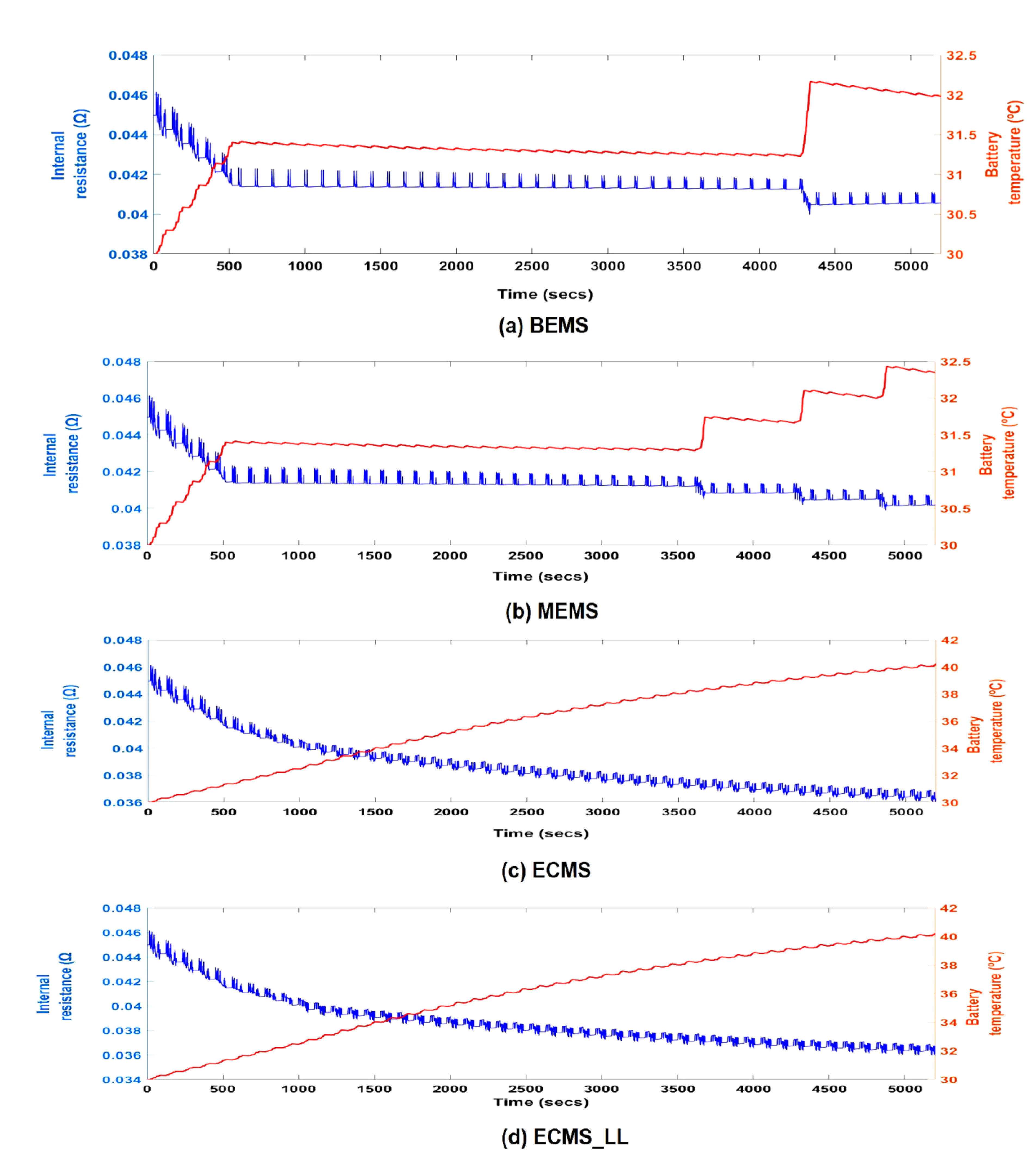
5.4. Battery Temperature

Table 6 shows the absolute battery temperature and battery temperature rise for the respective controllers considered for WMTC and IDC test cycles for the considered vehicle configuration. From Table 6, it is seen that the rise in battery temperature is found higher in the optimal controllers compared to rule-based strategies. The lithium-ion batteries are capable of operating from −20 to 60 °C [40]. Lithium-ion batteries have maximum efficiency when operated between 10 and 35 °C; this is called the optimum temperature range [40].
Figure 10 shows the variation of battery internal resistance along with the battery temperature for all the controllers tested for IDC test cycle with vehicle configuration Veh 1. With ECMS_LL and ECMS optimal controllers, the battery temperatures for all the test cases (irrespective of vehicle configuration and drive cycle) rise above 35 °C, which is the upper limit of the optimum temperature range. Increase in battery temperatures increases the degradation rates of the battery components, which includes maximum charge/discharge capacity, the effectiveness of the electrode in storing Li-ions, charge transfer rate constant, the total resistance of electrode resistance and electrode/electrolyte resistance [41]. The battery temperature rise with optimal controllers increases approximately up to five times when compared to rule-based strategies. It is seen that the optimal controllers provide a significant increase in the battery temperatures and it is known that higher battery temperature results in a faster battery degradation process [9,33]. Optimal controllers are designed to prioritize fuel economy and in the process, they exploit the battery operation, which leads to faster battery degradation when compared to rule-based controllers. The battery temperature is one of the key factors influencing the battery ageing. Using optimal control, the fuel economy benefit is achieved at the cost of increased battery temperature, which would accelerate the process of battery ageing.

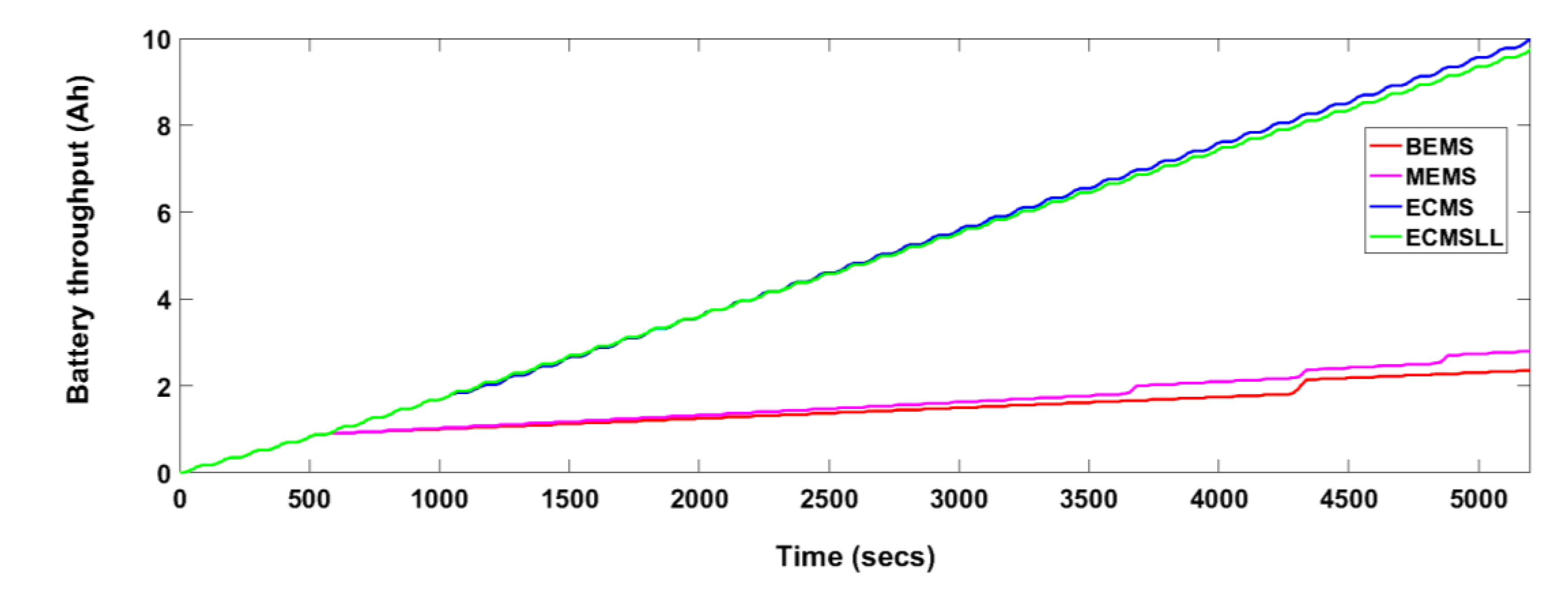
5.5. Battery Throughput

Figure 11 and Table 7 show the trends of battery throughput, for optimal based and rule-based controllers for different drive cycle and vehicle configuration considered. It is seen that optimal controllers ECMS and ECMS_LL show increased battery throughput when compared to rule-based BEMS and MEMS. Increased battery throughput is one of the potential factors affecting battery ageing [9,33,41]. Higher effective battery throughput increases the heat generation and thereby accelerating the battery ageing process [34,41]. The increased levels of battery throughput indicate faster battery ageing process with optimal controllers when compared to rule-based controllers.
The main objective of the cost function design was limited to improvement in fuel economy through improvement in the engine’s efficiency and appropriate power split during the vehicle run. To increase the engine’s efficiency, the battery is exploited to its fullest operation. In this process, the battery throughput increases to a maximum of five times when compared to the rule-based strategies. Frequent charging and discharging to accommodate the engine running in its optimum region increases the overall battery throughput for the journey. Battery throughput is a critical factor influencing the process of battery ageing [40].

5.6. Battery Charge and Dis-Charge C Rates
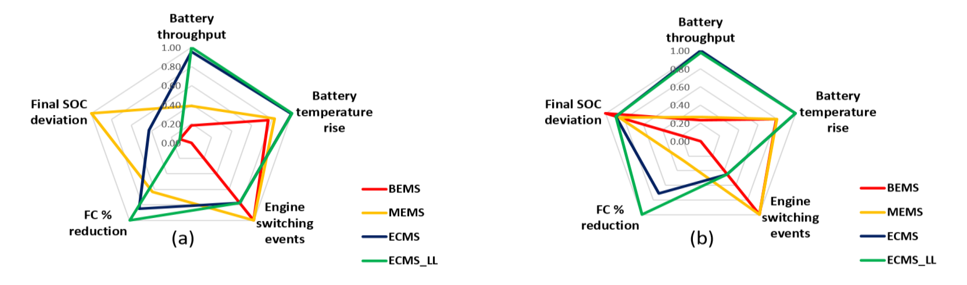
The distribution of charge and discharge C rate for rule-based and optimal control-based controllers tested for IDC test cycles and vehicle configuration Veh 1 is shown in Figure 12. The maximum charge rate limit for vehicle configuration Veh 1 is fixed to 5 C.
The figure clearly shows that the optimal controllers exhibit higher frequency and peaks of charge/discharge C rates when compared to rule-based strategies. A similar trend is found with the other vehicle configurations. Higher peaks of C rates, contribute to higher Joule heating, which in turn increases the internal temperature of the battery [34]. The higher C rates and higher frequency of charge and discharge cycles increase the battery temperature as well as battery throughput, thereby affecting the battery’s health and accelerating the ageing process [41]. The cost function designed in optimal controllers improves fuel economy by running the engine around the optimum region by employing the electric path wherever applicable. This, in turn, exploits the battery parameters which accelerates the battery ageing.

5.7. Discussion

Very limited work has been done on energy management control for two-wheeler HEVs. Most of the studies of energy management strategies on PHEVs were focussed on fuel economy, tailpipe emissions and charge sustenance. This study focuses on the aspect that optimal control-based energy management strategies with a desire to minimize fuel consumption display potential negative effects on the battery parameters influencing battery ageing. To study this an optimal based and a rule-based strategy was developed for parallel plugin hybrid two-wheeler. The study analysed all the critical battery parameters (battery temperature, charge/discharge C rate and battery throughput) along with engine switching and fuel economy and thereby evaluate the rule-based control strategies and optimal based control strategies. To display consistency and reliability of the results, the controllers were tested for two drive cycles and three different vehicle configurations. Two basic rule-based controllers, (a) BEMS and (b) MEMS, and two optimal control-based strategies, (c) ECMS and (d) ECMS_LL, were developed and considered for the evaluation.
The simulation results highlight that the optimal controllers considerably reduces the fuel consumption and engine-switching events when compared to rule-based controllers, irrespective of the drive cycles and vehicle configurations considered. The IDC test cycle results show a significant reduction in fuel consumption of up to 21.18% and a reduction in engine switching events of up to 55% with ECMS_LL when compared with rule-based strategy BEMS. However, the benefit of fuel consumption and engine switching showed significant adverse effects on the battery parameters influencing battery ageing. The battery temperature and battery throughput increased by 31% and 378% respectively.
Similarly, with the WMTC drive cycle, fuel consumption is reduced by 11.4% and ESE by 22.5%. However, there was a significant increase in battery temperature and battery throughput by 39% and 515%, respectively. Similar results are observed with other vehicle configurations. The optimal controller utilizes the electric path favourably to operate the engine in the most optimal region wherever possible. Thus, it reduces overall fuel consumption. Using the electric path for keeping the engine operation in the optimum region exploits battery usage, thus increasing the battery temperature, battery throughput and high peaks of charge/discharge C rates. These battery parameters, in turn, affect battery ageing.
The simulation results show that optimal controllers fare better when it comes to reducing the engine switching events. Unlike rule-based energy management strategies, ECMS cost function is designed to minimize fuel consumption at every instant of vehicle running. In ECMS cost function, the energy required for the operation of the starting system and extra fuel required to crank and start the engine is taken into account in the cost function. Thus, it inhibits unnecessary engine switching on/off. A benefit of 55% and a 22% reduction in engine switching events with IDC and WMTC drive cycles are noticed, respectively, for Veh 1 configuration. A similar trend of engine switching events has been observed with other vehicle configurations. This reduction in engine switching events helps in improving the starting system life and also the reliability of engine operation.
Figure 13 shows consolidated simulation results in the form of a radar chart for WMTC and IDC test cycles for vehicle 1 configuration. The normalized results of controllers (BEMS, MEMS, ECMS and ECMS_LL) for fuel consumption reduction, engine switching events, battery temperature rise, final SOC and battery throughput for WMTC and IDC test cycles are shown in Figure 13. The maximum and minimum are represented as ‘1’ and ‘0’, respectively, while comparing the controllers. The ‘1.0’ is defined as the maximum battery throughput, the maximum SOC deviation from target SOC, the maximum number of engine switching events, the maximum reduction of fuel consumption and the maximum rise in battery temperature and ‘0’ is defined as the minimum most.
It is evident from the simulation results that the optimal controllers have been able to provide the best fuel economy, minimal engine switching events and better SOC sustainability. However, the improvement in fuel consumption and engine switching has significant adverse effects on the battery health and the battery ageing factors (effective battery throughput, charge/discharge C rates and battery temperature). The battery temperature and battery throughput increased by a maximum of five times and the frequency and peaks of charge/discharge C rate have increased substantially. Similar results are observed with different vehicle configurations, as discussed in the results section. The benefit of fuel economy with energy management strategy is partially at the cost of battery health and ageing. Thus, consideration of battery parameters is a must in the evaluation of energy management strategies.
It can thus be suggested that optimal controllers, which are primarily designed for reducing fuel consumption, engine switching and charge sustenance for the particular test cycles display promising results for the control objectives considered. However, the simulation results show with optimal control-based strategies there is an increased negative effect on the battery ageing factors. This study emphasizes that the assessment of energy management strategy for HEV would be incomplete without considering the study of battery parameters influencing ageing and engine switching along with fuel economy. The comparison of controllers presented in this paper provides insights into the interdependency between fuel consumption, engine switching and battery parameters influencing the battery ageing.

6. Conclusions and Future Work

For an appropriate evaluation of energy management strategies, it is necessary to capture all the important factors related to the critical powertrain components. Battery replacement cost is one of the major hurdles in a PHEV that limit its prevalence in the automotive industry. Therefore, without consideration of the battery parameters influencing the battery ageing, the evaluation of energy management strategies remains incomplete.
This paper has analyzed an optimal control-based ECMS for a parallel plugin HEV two-wheeler. The paper presents an evaluation of rule-based and optimal control-based controllers for the HEV two-wheeler. A modified ECMS strategy, ECMS_LL, was proposed and developed. The ECMS_LL further improves fuel economy when compared to conventional ECMS by maximizing the convergence of the engine operating points to the optimum working region of the engine. This is done by exploiting the electric path favourably wherever necessary. From the simulation results, it is evident that the improvement in fuel economy is partly on the cost of battery health degradation.
This study emphasizes the need for an all-inclusive evaluation for the HEV energy management strategy. The work presented in this paper forms the basis for the future study of the optimal behaviour of energy management strategies, which would include battery ageing and engine switching events along with fuel economy and charge sustainability. The work emphasizes the requirement of an appropriate battery ageing-conscious energy management strategy to enhance the overall performance of PHEVs.
Designing an optimal control energy management with a consideration of battery parameters in the cost function formulation is taken as future work. The further development of a simple battery-ageing model to evaluate the battery capacity loss is under study. As a next step, the simulation results in this study are planned to be validated using HIL testing and then on the actual vehicle.

Author Contributions

Conceptualization, Methodology, Validation, and Writing—Original Draft Preparation: N.K.K.; Supervision: A.M. and A.A., Writing—Review & Editing: A.M., A.A. and D.Q.T. All authors have read and agreed to the published version of the manuscript.

Funding

This research received no external funding.

Conflicts of Interest

The authors declare no conflict of interest.

References

  1. Chan, C.C. The State of the Art of Electric and Hybrid Vehicles; IEEE: Piscataway, NJ, USA, 2002; Volume 90, pp. 247–275. [Google Scholar]
  2. Markel, T.; Simpson, A. Cost-benefit analysis of plug-in hybrid electric vehicle technology. World Electr. Veh. J. 2007, 1, 294–301. [Google Scholar] [CrossRef] [Green Version]
  3. Wirasingha, S.G.; Emadi, A. Classification and review of control strategies for plug-in hybrid electric vehicles. Trans. Veh. Technol. 2010, 60, 111–122. [Google Scholar] [CrossRef]
  4. Salmasi, F.R. Control strategies for hybrid electric vehicles: Evolution, classification, comparison, and future trends. Trans. Veh. Technol. 2007, 56, 2393–2404. [Google Scholar] [CrossRef]
  5. Zeng, Y.; Cai, Y.; Kou, G.; Gao, W.; Qin, D. Energy management for plug-in hybrid electric vehicle based on adaptive simplified-ECMS. Sustainability 2018, 10, 2060. [Google Scholar] [CrossRef] [Green Version]
  6. Huang, Y.J.; Yin, C.L.; Zhang, J.W. Design of an energy management strategy for parallel hybrid electric vehicles using a logic threshold and instantaneous optimization method. Int. J. Automot. Technol. 2009, 10, 513–521. [Google Scholar] [CrossRef]
  7. Škugor, B.; Deur, J.; Cipek, M.; Pavković, D. Design of a power-split hybrid electric vehicle control system utilizing a rule-based controller and an equivalent consumption minimization strategy. Proc. Inst. Mech. Eng. Part J. Automob. Eng. 2014, 228, 631–648. [Google Scholar]
  8. Chen, B.C.; Wu, Y.Y.; Wu, Y.L.; Lin, C.C. Adaptive power split control for a hybrid electric two-wheeler. IEEE Trans. Veh. Technol. 2011, 60, 1430–1437. [Google Scholar] [CrossRef]
  9. Tang, L.; Rizzoni, G.; Onori, S. Energy management strategy for HEVs including battery life optimization. Trans. Transp. Electrif. 2015, 1, 211–222. [Google Scholar] [CrossRef]
  10. Sun, C.; He, H.; Sun, F. The role of velocity forecasting in adaptive-ECMS for hybrid electric vehicles. Energy Procedia 2015, 75, 1907–1912. [Google Scholar] [CrossRef] [Green Version]
  11. Han, J.; Kum, D.; Park, Y. Synthesis of predictive equivalent consumption minimization strategy for hybrid electric vehicles based on closed-form solution of optimal equivalence factor. Trans. Veh. Technol. 2017, 66, 5604–5616. [Google Scholar] [CrossRef]
  12. Paganelli, G.; Delprat, S.; Guerra, T.M.; Rimaux, J.; Santin, J.J. Equivalent consumption minimization strategy for parallel hybrid powertrains. In Proceedings of the Vehicular Technology Conference. IEEE 55th Vehicular Technology Conference, Birmingham, AL, USA, 6–9 May 2002; Volume 4, pp. 2076–2081. [Google Scholar]
  13. Musardo, C.; Rizzoni, G.; Guezennec, Y.; Staccia, B. A-ECMS: An adaptive algorithm for hybrid electric vehicle energy management. Eur. J. Control 2005, 11, 509–524. [Google Scholar] [CrossRef]
  14. Serrao, L.; Onori, S.; Rizzoni, G. ECMS as a realization of Pontryagin’s minimum principle for HEV control. In Proceedings of the 2009 American Control Conference, St. Louis, MO, USA, 10–12 June 2009; pp. 3964–3969. [Google Scholar]
  15. Kim, N.; Cha, S.; Peng, H. Optimal control of hybrid electric vehicles based on Pontryagin’s minimum principle. Trans. Control Syst. Technol. 2010, 19, 1279–1287. [Google Scholar]
  16. Choi, S.S.; Lim, H.S. Factors that affect cycle-life and possible degradation mechanisms of a Li-ion cell based on LiCoO2. J. Power Sources 2002, 111, 130–136. [Google Scholar] [CrossRef]
  17. Vetter, J.; Novák, P.; Wagner, M.R.; Veit, C.; Möller, K.C.; Besenhard, J.O.; Hammouche, A. Ageing mechanisms in lithium-ion batteries. J. Power Sources 2005, 147, 269–281. [Google Scholar] [CrossRef]
  18. Broussely, M.; Biensan, P.; Bonhomme, F.; Blanchard, P.; Herreyre, S.; Nechev, K.; Staniewicz, R.J. Main aging mechanisms in Li ion batteries. J. Power Sources 2005, 146, 90–96. [Google Scholar] [CrossRef]
  19. Belt, J.R.; Ho, C.D.; Miller, T.J.; Habib, M.A.; Duong, T.Q. The effect of temperature on capacity and power in cycled lithium ion batteries. J. Power Sources 2005, 142, 354–360. [Google Scholar] [CrossRef]
  20. Serrao, L.; Onori, S.; Sciarretta, A.; Guezennec, Y.; Rizzoni, G. Optimal energy management of hybrid electric vehicles including battery aging. In Proceedings of the 2011 American Control Conference, San Francisco, CA, USA, 29 June–1 July 2011; pp. 2125–2130. [Google Scholar]
  21. Kum, D.; Peng, H.; Bucknor, N.K. Control of engine-starts for optimal drivability of parallel hybrid electric vehicles. J. Dyn. Syst. Meas. Control 2013, 2, 135. [Google Scholar] [CrossRef]
  22. Kim, H.; Kim, J.; Lee, H. Mode transition control using disturbance compensation for a parallel hybrid electric vehicle. Proc. Inst. Mech. Eng. Part J. Automob. Eng. 2011, 225, 150–166. [Google Scholar] [CrossRef]
  23. Babu, D.S.; Raj, S.S.; Malsoor, B. Stability Enhancement of A Powered Two Wheeler Vehicle Under Curve Negotiation. Int. Refereed. J. Eng. Sci. 2016, 5, 62–71. [Google Scholar]
  24. Delavaux, M.; Lhomme, W.; McGordon, A. Comparison between forward and backward approaches for the simulation of an electric vehicle. In Proceedings of the IEEE Vehicle Power and Propulsion Conference (VPPC2010), Lille, France, 3–5 September 2010. [Google Scholar]
  25. Dixon, G.; Stobart, R.; Steffen, T. Unified Backwards Facing and Forwards Facing Simulation of a Hybrid Electric Vehicle using MATLAB Simscape. SAE Tech. Paper 2015. [Google Scholar] [CrossRef] [Green Version]
  26. Paganelli, G.; Guerra, T.M.; Delprat, S.; Santin, J.J.; Delhom, M.; Combes, E. Simulation and assessment of power control strategies for a parallel hybrid car. Proc. Inst. Mech. Eng. Part J. Automob. Eng. 2000, 214, 705–717. [Google Scholar] [CrossRef]
  27. Tremblay, O.; Dessaint, L.A. Experimental validation of a battery dynamic model for EV applications. World Electr. Veh. J. 2009, 3, 289–298. [Google Scholar] [CrossRef] [Green Version]
  28. Tremblay, O.; Dessaint, L.A.; Dekkiche, A.I. A generic battery model for the dynamic simulation of hybrid electric vehicles. In Proceedings of the 2007 IEEE Vehicle Power and Propulsion Conference, Arlington, TX, USA, 9–12 September 2007; pp. 284–289. [Google Scholar]
  29. Hussein, A.A.H.; Batarseh, I. An overview of generic battery models. In Proceedings of the 2011 IEEE Power and Energy Society General Meeting, At Detroit, Michigan, USA, 24–29 July 2011; pp. 1–6. [Google Scholar]
  30. Wang, D.; Bao, Y.; Shi, J. Online lithium-ion battery internal resistance measurement application in state-of-charge estimation using the extended Kalman filter. Energies 2017, 10, 1284. [Google Scholar] [CrossRef] [Green Version]
  31. Vignesh, B.R.; Grandjean, T.; McGordon, A.; Greenwood, D. Thermal modeling of lithium ion batteries for temperature rise predictions in hybrid vehicle application. In Proceedings of the 2018 Thirteenth International Conference on Ecological Vehicles and Renewable Energies (EVER), Monte Carlo, Monacco, 10–12 April 2018; pp. 1–7. [Google Scholar]
  32. Onori, S.; Serrao, L.; Rizzoni, G. Adaptive equivalent consumption minimization strategy for hybrid electric vehicles. In Proceedings of the ASME 2010 dynamic systems and control conference, Cambridge, MA, USA, 13–15 September 2010; pp. 499–505. [Google Scholar]
  33. Vignesh, B.R. Parametric Modelling, Simulation and Validation of Lithium Ion Batteries for Temperature Rise Prediction in Hybrid Two-Wheelers. Ph.D. Thesis, University of Warwick, Coventry, UK, 2016. [Google Scholar]
  34. Srinivasan, R.; Baisden, A.C.; Carkhuff, B.G.; Butler, M.H. The five modes of heat generation in a Li-ion cell under discharge. J. Power Sources 2014, 262, 93–103. [Google Scholar] [CrossRef]
  35. Onori, S.; Serrao, L. On Adaptive-ECMS strategies for hybrid electric vehicles. In Proceedings of the International Scientific Conference on Hybrid and Electric Vehicles, RHEVE 2011, Malmaison, France, 6–7 December 2011; Volume 67. [Google Scholar]
  36. Urdhwaresh, R. Limits, Regulations, Measurement of Exhaust Emissions and Calculation of Fuel Consumption. In Indian Emissions Regulations; Automotive Research Association of India: Pune, India, 2017. [Google Scholar]
  37. Windover, P.R.; Owens, R.J.; Levinson, T.M.; Laughlin, M.; Gaines, L. Stop and Restart Effects on Modern Vehicle Starting System Components; Argonne National Lab. (ANL): Argonne, IL, USA, 2015. [Google Scholar]
  38. Sciarretta, A.; Guzzella, L. Control of hybrid electric vehicles. Ieee Control Syst. Mag. 2007, 27, 60–70. [Google Scholar]
  39. Paganelli, G.; Ercole, G.; Brahma, A.; Guezennec, Y.; Rizzoni, G. General supervisory control policy for the energy optimization of charge-sustaining hybrid electric vehicles. JSAE Rev. 2010, 22, 511–518. [Google Scholar] [CrossRef]
  40. Warner, J.T. The Handbook of Lithium-ion Battery Pack Design: Chemistry, Components, Types and Terminology; Elsevier: Amsterdam, The Netherlands, 2005. [Google Scholar]
  41. Leng, F.; Tan, C.M.; Pecht, M. Effect of temperature on the aging rate of Li ion battery operating above room temperature. Sci. Rep. 2015, 5, 12967. [Google Scholar] [CrossRef] [Green Version]
Figure 1. Vehicle powertrain architecture of the hybrid two-wheeler considered.
Energies 13 03122 g001
Figure 2. Equivalent circuit model of the battery.
Energies 13 03122 g002
Figure 3. Control data flow block.
Energies 13 03122 g003
Figure 4. Vehicle speed and wheel power for (a) Worldwide Motorcycle Test Cycle (WMTC) and (b) Indian Drive Cycle (IDC).
Energies 13 03122 g004
Figure 5. Energy flow diagram of a PHEV during (a) Battery charging and (b) Battery recharging through engine [26].
Energies 13 03122 g005
Figure 6. An example of state of charge (SOC) penalty weight used in ECMS [39].
Energies 13 03122 g006
Figure 7. Relationship between the new equivalence factor ‘γs’ and gain ‘ β ’ for 3 different system configurations: (a) Veh1, (b) Veh2 and (c) Veh3 tested for WMTC and IDC test cycles
Energies 13 03122 g007
Figure 8. Veh1 engine operating points for different controllers tested for the WMTC test cycle: (a) (BEMS), (b) MEMS, (c) ECMS and (d) ECMS_LL.
Energies 13 03122 g008
Figure 9. Veh1 engine operating points for different controllers tested for the IDC test cycle: (a) BEMS, (b) MEMS, (c) ECMS and (d) ECMS_LL.
Energies 13 03122 g009
Figure 10. Battery internal resistance and temperature profiles for Veh 1 configuration tested for the IDC test cycle: (a) BEMS, (b) MEMS, (c) ECMS and (d) ECMS_LL.
Energies 13 03122 g010
Figure 11. Battery throughput profile for the IDC test cycle.
Energies 13 03122 g011
Figure 12. Battery SOC and charge C rate for Veh 1 configuration for different controllers tested for IDC test cycle: (a) BEMS, (b) MEMS, (c) ECMS and (d) ECMS_LL.
Energies 13 03122 g012
Figure 13. Simulation results for the Veh 1 configuration considered: (a) WMTC test cycle and (b) IDC test cycle.
Energies 13 03122 g013
Table 1. Vehicle configuration table.
Vehicle ConfigurationEngine SizingBattery Charge C Rate
Veh 180%5 C
Veh 2100%3 C
Veh 370%1 C
Table 2. Basic rules used in rule-based strategy existing in the hybrid two-wheeler considered.
ModeStateBatteryVehicle ConditionsEngMotGenDescriptions
Launch modeVehicle launchSOC > SOCLowlimitV > 0, DT < MmtOffOnOffVehicle start condition with motor alone providing the drive torque
Vehicle launchSOC > SOCLowlimitV > 0, DT > MmtOnOnOffVehicle start condition with motor and ICE providing the drive torque
Vehicle launchSOC < SOCLowlimitV > 0OnOffOffVehicle start condition with engine alone providing the drive torque
Pure EV-modeEV stateSOC > SOCLowlimitMmn > V > 0 and DT < MmtOffOnOffVehicle run condition with motor providing the drive torque
ICE-modeCharging stateSOC < SOCLowlimit 0 < V < Mmn,
DT < Met
OnOffOnDrive torque provided by ICE alone and battery charged by engine
ICE only stateSOC < SOCLowlimit V > Mmn or DT > MetOnOffOffDrive torque provided by ICE alone
Combined modeHigh power demandSOC > SOCLowlimit V < Mmn,
DT > Mmt
OnOnOffDrive torque provided by both motor and ICE
Regeneration modeBraking stateSOC < SOCHighlimitDT < 0, V > MgnOffOffOffNo regenerative braking
Braking stateSOC < SOCHighlimitDT < 0, V < MgnOffOffOnRegenerative braking
Braking stateSOC > SOCHighlimitDT < 0OffOffOffNo regenerative braking
where V = vehicle velocity; Mmn = maximum speed limit of the motor/generator; Mmt = maximum motor torque limit; Met = maximum engine torque limit; Men = maximum engine speed limit; Mcn = minimum clutch engage speed; DT = demand torque; SOCLowlimit = lower SOC limit (20% SOC) and SOCHighlimit = higher limit SOC limit (80% SOC).
Table 3. Absolute fuel consumption and fuel consumption reduction percentage for different controllers tested with the WMTC and IDC test cycle for Veh 1, Veh 2 and Veh 3.
ControllersVeh 1Veh 2Veh 3
WMTCIDCWMTCIDCWMTCIDC
Abs FC (gms)FC Red (%)Abs FC (gms)FC Red (%)Abs FC (gms)FC Red (%)Abs FC (gms)FC Red (%)Abs FC (gms)FC Red (%)Abs FC (gms)FC Red (%)
BEMS146.70.0142.80.0148.10.0148.00.0145.70.0141.10.0
MEMS138.15.9139.12.6146.31.3145.31.8144.11.1138.12.1
ECMS137.16.5129.39.4144.02.8139.06.0143.21.7133.05.7
ECMS_LL130.011.4112.621.2136.57.9121.817.7140.03.9128.29.1
Table 4. Final SOC values for different vehicle configuration and drive cycles.
ControllersVeh 1Veh 2Veh 3
WMTCIDCWMTCIDCWMTCIDC
BEMS0.300.310.310.310.310.32
MEMS0.330.310.320.310.310.31
ECMS0.300.300.300.300.300.30
ECMS_LL0.300.300.300.300.300.30
Table 5. Engine switching event for different controllers tested for different vehicle configurations (Veh1, Veh2 and Veh3) and test cycles (WMTC and IDC).
ControllersVeh 1Veh 2Veh 3
WMTCIDCWMTCIDCWMTCIDC
BEMS899689968996
MEMS899689968996
ECMS694369436943
ECMS_LL694369436943
Table 6. Battery temperature and battery temperature rise for different vehicle configurations tested for WMTC (W) and IDC (I) test cycles.
ControllersAbsolute Battery Temperature (°C)Battery Temperature Rise (°C)
Veh 1Veh 2Veh 3Veh 1Veh 2Veh 3
WIWIWIWIWIWI
BEMS31.432.031.431.931.731.81.42.01.41.91.71.8
MEMS33.932.333.232.133.332.33.92.33.22.13.32.3
ECMS41.741.241.041.439.338.411.711.211.011.49.38.4
ECMS_LL43.841.944.342.042.738.413.811.914.312.012.78.4
Initial battery temperature considered for the study = 30 °C.
Table 7. Absolute battery throughput and battery throughput rise in percentage for different vehicle configurations tested for WMTC (W) and IDC (I) test cycles.
ControllersBattery throughput in AhBattery throughput Rise in %
Veh 1Veh 2Veh 3Veh 1Veh 2Veh 3
WIWIWIWIWIWI
BEMS1.82.31.72.32.02.4000000
MEMS3.72.73.02.53.73.152137468429
ECMS9.510.59.410.79.09.5437350446357349290
ECMS_LL10.911.211.511.211.09.5516378566381451291

