Article

A Piston-Swiveling-Cylinder Pair in a High Water-Based Hydraulic Motor with Self-Balanced Distribution Valves

1
School of Mechatronic Engineering, China University of Mining and Technology, Xuzhou 221116, China
2
Center for Hypergravity Experimental and Interdisciplinary Research, Zhejiang University, Hangzhou 310058, China
*
Author to whom correspondence should be addressed.
Energies 2020, 13(12), 3175; https://doi.org/10.3390/en13123175
Submission received: 14 May 2020 / Revised: 13 June 2020 / Accepted: 15 June 2020 / Published: 19 June 2020
(This article belongs to the Special Issue Intelligent Fluid Power Drive Technology)

Abstract

:
To improve the low viscosity and poor lubrication characteristics of high-water-based hydraulic liquid, the abrasion and leakage problems in hydraulic components need to be addressed. In a high water-based hydraulic motor with self-balanced distribution valve (HWBHM-SDV), there are two key friction pairs: the piston-crankshaft pair and piston-swivelling-cylinder (PSC) pair. To study the working performance of the PSC pair in HWBHM-SDV, we firstly designed the structural parameters. We found that, within the working speed 0–100 rpm, the leakage in the PSC pair is mainly caused by pressure-gradient flow, and the influence of the seal will not be significant when the seal length is 24 mm. Then, the friction coefficients of different matching materials were tested. It was found that the friction coefficient of 316L stainless steel with OVINO-GIC (OVINO-graphite intercalated compound) coating (316L-GIC)/PEEK reinforced with 30% carbon fibre (PEEK-30CF) is about 0.02~0.04, and the friction coefficient of 316L-GIC/316L-GIC is about 0.05–0.07. Finally, the influences of factors (clearance, temperature, pressure, and material) on leakage performance were analysed based on an orthogonal test method considering fluid-structure interaction. It was found that clearance has the most significant influence on leakage, followed by pressure and liquid temperature, and the difference between matching materials 316L-GIC/316L-GIC and 316L-GIC/PEEK-30CF is insignificant when the clearance is less than 8 μm and the working pressure is less than 10 MPa. Moreover, the difference in volume efficiency loss between theoretical analysis and calculated result considering fluid-structure interaction increases with the increase of working pressure and working speed. To ensure good working performance of a PSC pair, matching materials 316L-GIC/PEEK-30CF could be selected for pressures below 15 MPa, while 316L-GIC/316L-GIC could be used at 28 MPa.

Graphical Abstract

1. Introduction

A high water-based hydraulic system (HWBHS) has better fire-resistance, lower environmental impact, lower operating cost, greater rigidity, and more accurate positioning ability compared with oil hydraulic systems. Since the 1980s, HWBHS has been widely used in food processing, ocean engineering, and mining engineering [1,2,3,4].
As the key actuating component, HWBHM has been studied for use in HWBHS [5,6,7,8,9,10,11,12]. An HWBHM with low speed and large torque has the advantages of compact structure and convenient layout. It has special benefits that can be used in limited spaces where low speed and high torque output is required but there no space for a reduction device. In contrast, HWBHM need reduction devices to get low speed and high torque. HWBHM with low speed and high torque has wide application prospects, e.g., in tunnel boring machines, hydraulic winches, and hand-held emulsion drilling machines, etc. In traditional axial/radial pump/motors working with high water-based hydraulic liquid (HWBHL), the flow distribution mechanism is usually a valve plate, and most HWBHMs operate at high speed due to the characteristics of the valve plate. To improve the volume efficiency and abrasive resistance of friction pairs in an HWBHM, the key wear and lubrication problems of the valve plate in a high water-based hydraulic motor/pump have been studied. The structure of the valve plate has significant influence on the volumetric efficiency of a traditional hydraulic pump (Marning [13], Seeniraj [14], Wang [15], and Yang [16]), and numerical simulation of the relationship between leakage flow and clearance in flow distribution pair was implemented by Wang [17]. In addition, a satellite motor that can be fed with various liquids was designed by Śliwiński, and the flow of liquids (including oil and emulsion) in flat gaps was analysed [18]. The low viscosity and poor lubrication characteristics of HWBHL directly limited the development of HWBHMs, especially HWBHMs working with low speed and high torque. Anyhow, leakage caused by the valve plate in a HWBHM is inevitable. Thus, to promote the volume efficiency and working life of HWBHM working at low speed (less than 100 rpm), an HWBHM with a self-balanced valve (SDV) distribution mechanism has been introduced in our previous work [19]. For the SDV distribution mechanism, a cone valve has strong self-compensation capability and is leak-proof. Thus, the leakage caused by the valve plate in HWBHM could be alleviated.
In addition, to improve the working efficiency and working life of HWBHM, the friction and leakage problems of a piston-cylinder pair with lubrication of HWBHL still need to be addressed. As shown by Wang, based on hydraulic oil film theory, with the same clearance, the leakage caused by a piston-cylinder pair is larger than other friction pairs such as the distribution pair and slipper pair in construction machinery remanufactured piston motors [20]. Analogue experiments involving the piston-cylinder pair in internal a curved radial piston motor were implemented by Olsson [21]: the experimental results showed that the effects of abrasion would be greater when the motor is working with water-glycol at low speed. An optimal clearance formula of a piston friction pair for water hydraulic pump based on thermal balance principle was proposed by Huang [22,23]. The analysis showed that a minimum thermal clearance exists in each piston friction pair, and the factors of friction coefficient, matching materials and piston diameter, etc., should be considered. Cao [24] studied the stress state and leakage in a piston-cylinder pair in hydraulic axial piston pump, pointing out that proper clearance and materials should be considered to solve the friction performance in a water hydraulic pump. Experimental research on materials used for both a piston and cylinder in a water hydraulic pump has been implemented by Yang [25]. The results of this study indicated that it is more suitable to use stainless steel matched with plastics as the materials of piston and cylinder in a water hydraulic axial piston pump. Several materials (metal, engineering ceramics, and plastics) and engineering technologies for the main friction pairs in a water hydraulic piston pump were tested: the result showed that a hard-to-soft scheme forms a feasible matching pair with water lubrication [26,27,28]. To improve the load bearing of, and reduce leakage from a piston-cylinder pair in axial piston machine at high pressure with water as the hydraulic liquid, Ernst [29,30] investigated the influences of different surface shapes on pressure build-up, leakage, and torque loss. The previous research laid a foundation for the further study of hydraulic elements with lubrication of HWBHL.
To deal with the friction and leakage problems, and study the influences of various factors (seal length, clearance, temperature and materials) on leakage performance of PSC pair in HWBHM with SDV, it is necessary to provide guidance regarding the design of and materials chosen for the PSC pair in HWBHM with SDV. Firstly, the basic structure and motion performance of a PSC pair were analysed, and the structure of the PSC was designed. Then, a friction experiment was applied to analyse the frictional characteristics of the matching pairs, namely (1) a hard-to-soft matching scheme of 316L stainless steel with OVINO-GIC coating (316L-GIC) and PEEK reinforced with 30% carbon fibre (PEEK-30CF), (2) a hard-to-hard matching scheme of 316L-GIC and 316L-GIC. Finally, the influences of various factors (clearance, temperature, pressure, and materials) on the leakage performance of PSC pair in HWBHM were analysed based on an orthogonal test design considering fluid-structure interaction, and the feasibility of clearance sealing for PSC pair in HWNHM working at low speed was studied.

2. Model of PSC Pair in HWBHM with SDV

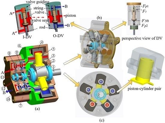
The proposed new type HWBHM with SDV [18] is shown in Figure 1. The HWBHM mainly consists of two parts: the SDV groups are shown in Figure 1b and the piston pairs are shown in Figure 1c. As shown in Figure 1, there are five pistons in the HWBHM, and the distribution of each piston is realised through one inlet distribution valve (I-DV) and one outlet distribution valve (O-DV). The I-DV and O-DV have the same structures, the DVs all consist of five parts: a valve guiding, spring, valve, valve seat, and rod. When I-DV and O-DV are in on or off states, the hydraulic force upon the valve Fp1 is equal to the hydraulic force under the valve Fp2. The support force from valve seat FN0 is equal to the spring force Ft in an off state. The motion of the valve in DV is controlled by a rod, while the force exerted by the rod is decided by the spring force and hydrodynamic force, and the spring force and hydrodynamic force are very small at low working speeds. For the applied valve seal, the proposed SDV could reduce the significant volume efficiency loss problem caused by the valve plate distribution mechanism. Besides, unlike the case in an axial piston motor, the lateral force for PSC pair in HWBHM is relatively small. The wear seen in PSC pairs could be alleviated, but leakage and friction between piston and swivelling cylinder still need to be addressed.
The conflicts between lubrication and wear, sealing and leakage are common challenges in the engineering of friction pairs. For a PSC pair in HWBHM with SDVs, there are mainly two kinds of sealing mode: non-contact sealing (a clearance seal) and contact sealing mode (using a sealing ring). For a clearance seal, the friction pairs are under lubricated conditions most of the time, which has the advantage of minor abrasion between friction pair components. Thus, the working life of a friction pair with clearance seal mode would be longer than that in contact seal mode (the clearance would, however, affect the volume efficiency of the HWBHM).
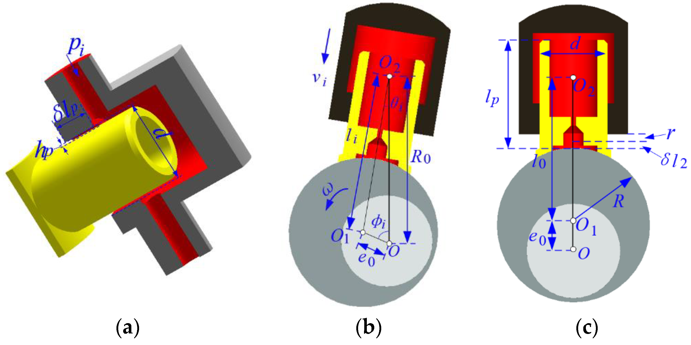
The basic structure of a PSC pair is shown in Figure 2a: it consists of a piston and a swivelling cylinder. The diameter of the piston is d, the seal length in the PSC pair is δlp, and the clearance between piston and swivelling cylinder is hp.
The motion of a piston in its cylinder at an arbitrary position is shown in Figure 2b, O represents the centre of rotation of the crankshaft, O1 represents the eccentricity of the structure on the crankshaft, O2 represents the centre of rotation of the cylinder, e0 represents the distance between O and O1, R0 is the distance between O and O2, θi represents the angle of rotation of the cylinder, φi denotes the angle of rotation of the crankshaft, ω represents the angular velocity of the crankshaft, and li is the distance between O1 and O2. A PSC pair at position φi = 0 is shown in Figure 2c. For the proposed HWBHM with SDV, the designed displacement q is 189 mL/r, the rated rotation speed is 60 rpm, and maximum rotation speed is 100 rpm. The corresponding basic parameters in Figure 2 are listed in Table 1.
As shown in Figure 2b, when the crankshaft is at position φi, the relative velocity vi between the piston and swivelling cylinder can be expressed as [18]:
v i = ω R 0 sin θ i = ω R 0 e 0 sin ϕ i / l i
In Equation (1), li is calculated as: l i = e 0 2 + R 0 2 2 e 0 R 0 cos ϕ i .
Thus, the variation of velocity vi with angular position φi can be obtained (Figure 3). The maximum relative velocity vi between piston and swivelling cylinder will be less than 0.2 m/s when the working speed of HWBHM is no more than 100 rpm.

3. Leakage Analysis and Initial Design for a PSC Pair

3.1. Seal Length and Fit Tolerance

Leakage and abrasion are two important indices used to measure the performance of friction pairs. For the designed PSC pair, sealing length and clearance are two main design parameters, considered simultaneously with the matching materials. The leakage in clearance could be divided into two parts: leakage caused by the working pressure and that caused by relative motion between the piston and swivelling cylinder. Since the lateral force for the PSC pair in an HWBHM is relatively small, or zero, in some working states, the leakage in the PSC pair in an HWBHM is assumed to be the leakage from a concentric circular annulus. The flow in the clearance is influenced by many factors, such as liquid performance, Renolds number, clearance size, temperature, etc. Because the clearance of the PSC pair is quite small, the liquid is assumed to be laminar at the initial analysis. Without consideration of structural deformation, the pressure-flow relationship caused by the pressure-gradient flow for one PSC pair in laminar status can be expressed as [31]:
δ q h p = π d h p 3 12 μ δ l p Δ p i
where, δqhp is the leakage caused by the pressure in the PSC pair, Δpi is the differential pressure across the clearance, and μ is the dynamic viscosity of the HWBHL.
In the HWBHM-SDV, an emulsion with 95% water is selected as the transmission medium. For water accounts for a large proportion of emulsion, the performance of emulsion is close to water. Thus, water was used in the simulation instead of emulsion to investigate the worst working state in this study.
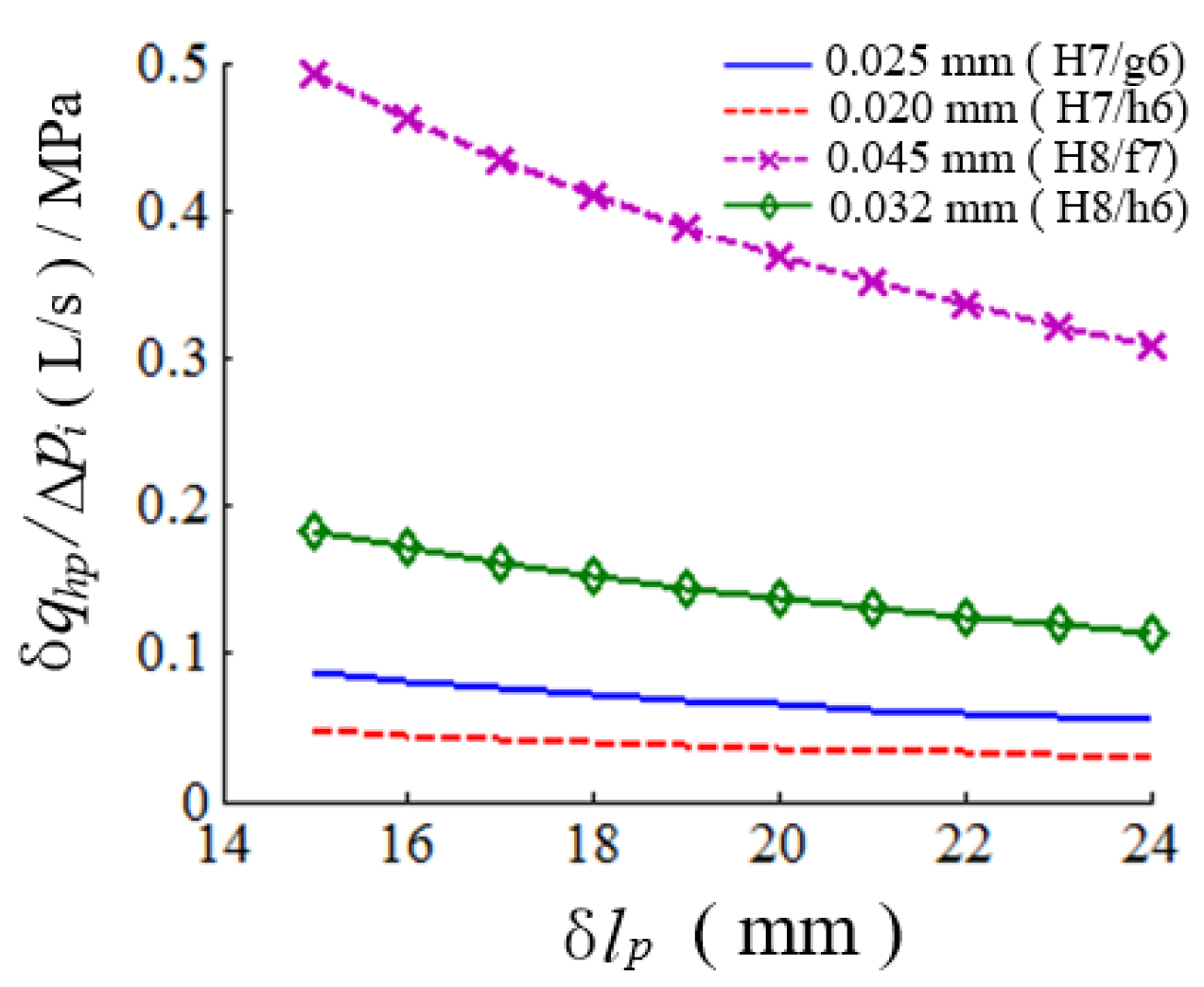
For the fit tolerance usually used in a PSC pair, the variations of δqhppi with sealing length δlp under the maximum clearance of fit tolerance H7/g6, H7/h6, H8/f7, H8/h7 are shown in Figure 4. The clearance leakage δqhp decreases with the increase of sealing length δlp, and the change in leakage is insignificant when δlp reaches 24 mm. Thus, simultaneously considering the structure limitation for PSC pair, the value of δlp could be set to be 24 mm.
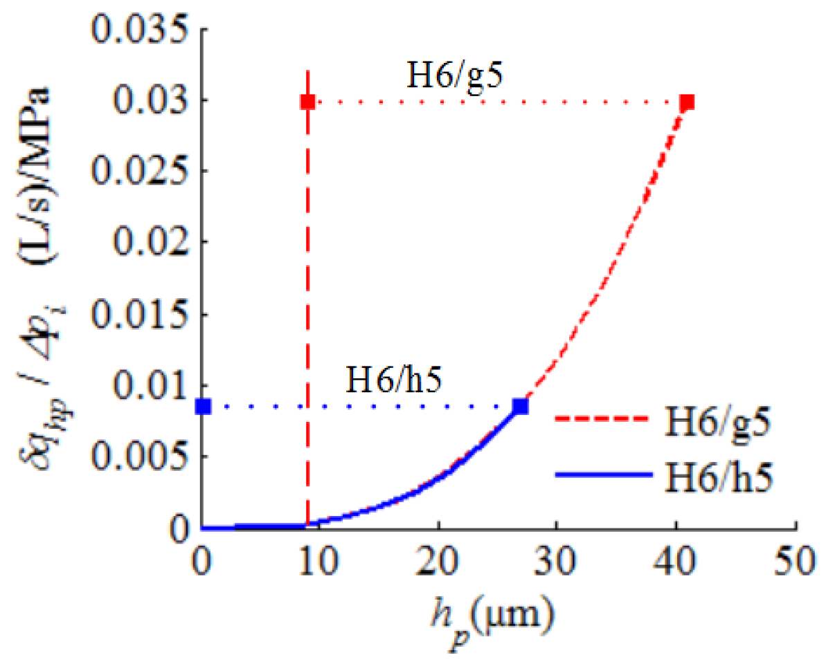
To improve the working efficiency of an HWBHM working under low-speed, high-pressure conditions, the accuracy of fit tolerance should be improved. With the seal length of 24 mm, the variations of δqhppi under higher fit tolerance H6/h5 and H6/g5 are shown in Figure 5, the leakage problem can be improved by improving the fit precision. It also can be concluded that the leakage would be very low when the clearance in the PSC pair is less than 10 μm.
Simultaneously, the leakage δqτ caused by shear flow in piston and swivelling cylinder clearance can be expressed as:
δ q τ = π d h p v i / 2
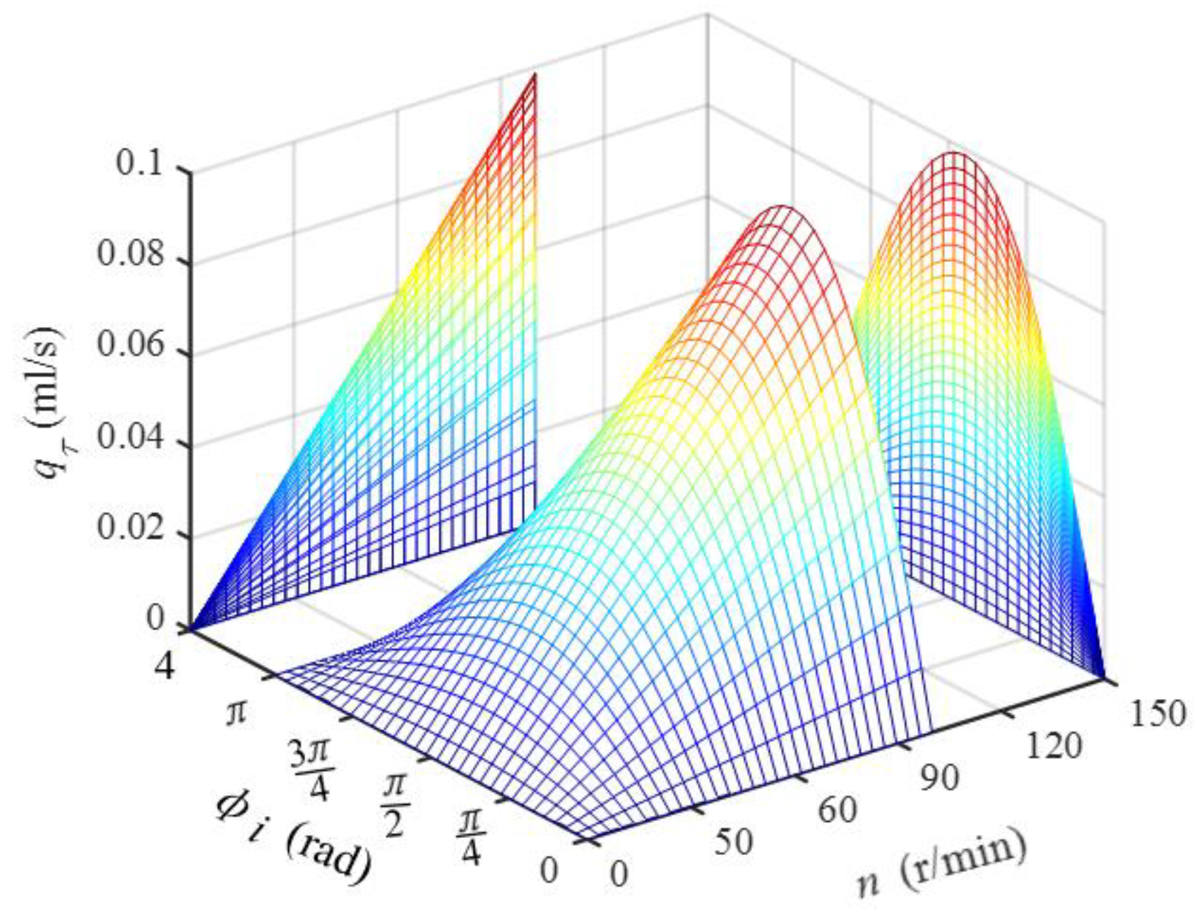
Thus, the leakage δqτ caused by Couette flow can be calculated through the combination of Equations (1) and (3) when considering the motion of a PSC pair. The variation of leakage δqτ with rotation speed n and angular position φi of the crankshaft with design parameters (hp, δlp) = (10 μm, 24 mm) are shown in Figure 6. It can be concluded that the leakage δqτ caused by shear flow increases with the increase of rotation speed n, and the maximum leakage δqτ is less than 0.1 mL/s. Hence, the leakage caused by the motion of the PSC could be ignored compared with the leakage caused by the pressure difference.

3.2. Temperature

The energy loss caused by leakage causes a temperature rise in a PSC pair. Energy loss Ehp caused by pressure-gradient flow Ehp can be expressed by Equation (4):
E h p = Δ p i δ q h p = π d h p 3 12 μ δ l p Δ p i 2
With the assumptions that the energy loss is all converted heat to increase the temperature of HWBHL, and the energy dissipation is ignored, the temperature rise ΔTp caused by energy loss Ehp can be expressed by Equation (5):
Δ T p = E h p / ρ C δ q h p
where, C is the specific heat capacity of HWBHL, and ρ is the density thereof.
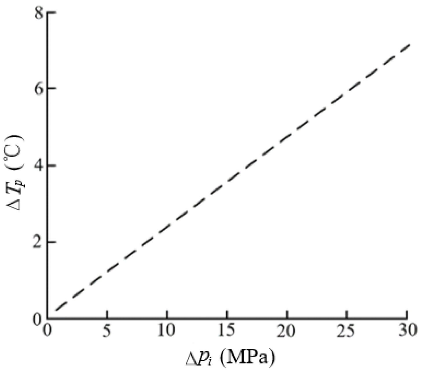
The variation in temperature increase based on Equation (6) is shown in Figure 7 with parameters ρ = 103 Kg/m3 and C = 4.2 × 10³ J/(Kg·°C): the temperature increase caused by pressure-gradient flow increases with the increase of working pressure Δpi, the value of ΔTp is about 7 °C when the working pressure is 30 MPa.
Compared with the influence of pressure, the viscosity of HWBHL would be more significantly influenced by temperature [32]. The relationship between dynamic viscosity μ and temperature T of water is shown in Table 2 [33].

3.3. Fluid-Structure Interaction

At the actual working state, when the pressure p in the cylinder chamber is high, there would form a lubrication film between cylinder and piston. Then the pressure distribution in the lubrication film and pressure p acting on cylinder chamber and piston would lead to the deformations of cylinder Δhps and piston Δhpp. Thus, the deformations of cylinder and piston would lead to the pressure redistribution in the lubrication film. Simultaneously, the leakage in the lubrication film would cause the liquid temperature to rise, thus changing the viscosity of HWBHL, directly influencing the influencing the leakage, pressure distribution in the lubrication film, and causing deformation of the structure. Without considering the deformation of cylinder and piston that is caused by the temperature rise, and assuming that the temperature of liquid is constant, interactions between structures (cylinder and piston) and lubrication film are shown in Figure 8.
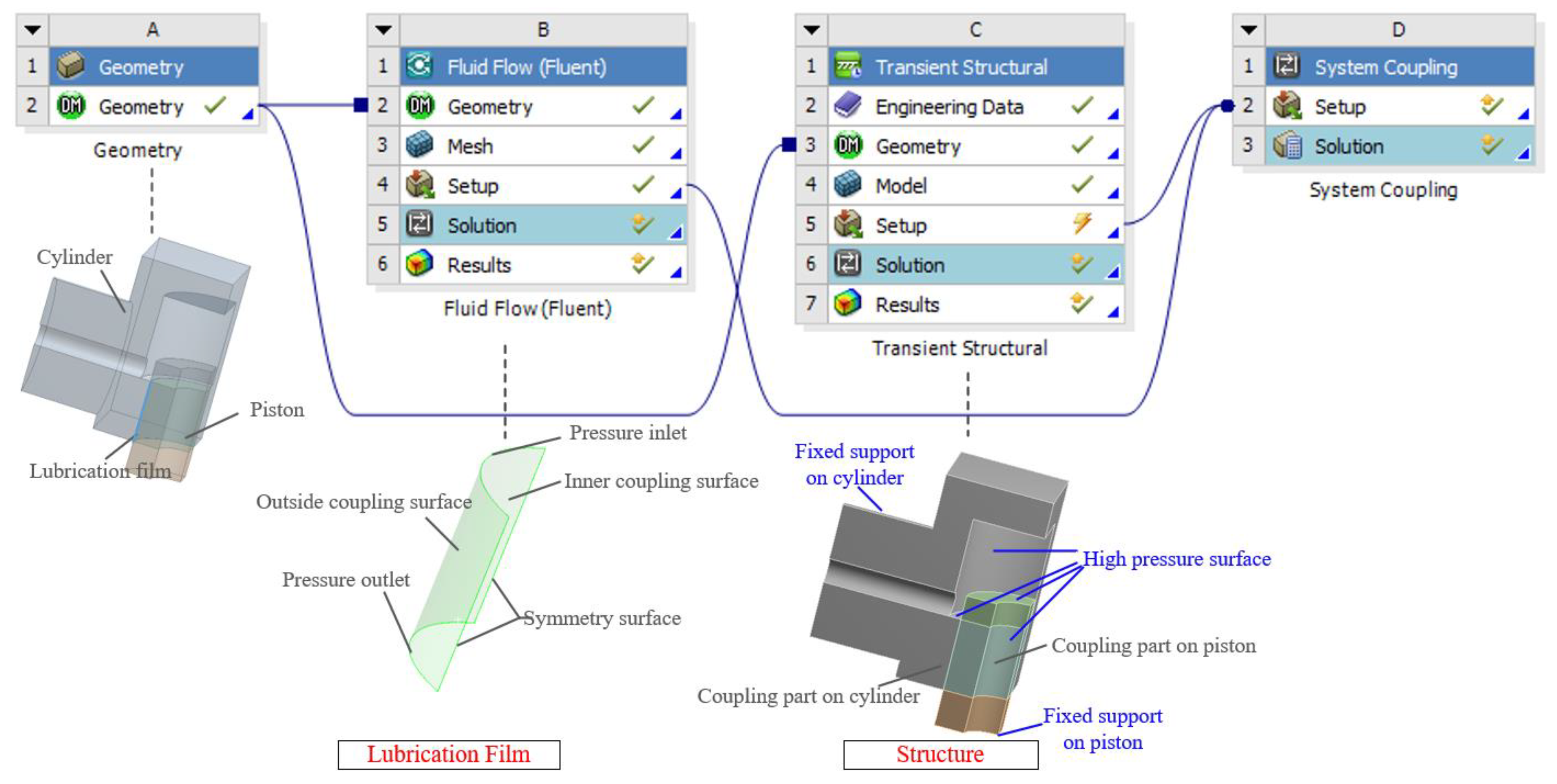
To investigate the influence of fluid-structure interaction on leakage in PSC pair, the method of fluid-structure coupling analysis was implemented through commercial software ANSYS 15.0 (version 15.0.0, ANSYS, south of Pittsburgh in Canonsburg, PA, USA). The simulation was conducted by the combination of a Fluid Flow (Fluent) module and Transient Structure module. There are two pairs of coupling surfaces: one is the outside coupling surface on the lubrication film and coupling part on the cylinder, the other is inner coupling surface on the lubrication film and coupling part on the piston. Considering the symmetry characteristic of the structure, a ¼-scale model is established to simulate the fluid-structure interaction. The analysis model is shown in Figure 9. In the setting, temperature is set to be constant.
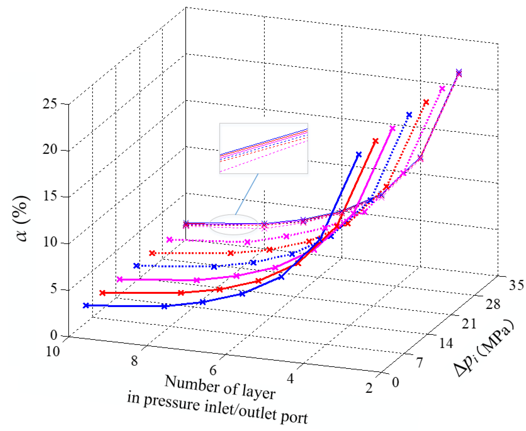
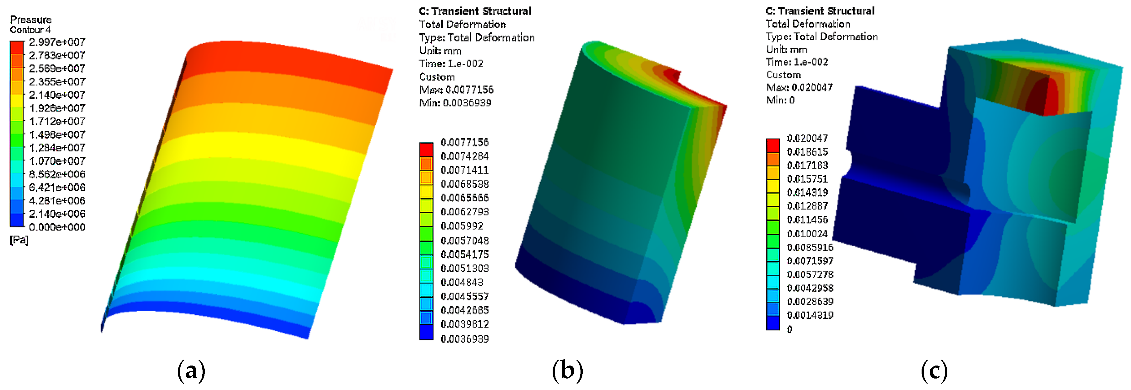
The grid number might have significant influence on the simulation result. Firstly, in order to ensure the reliability of simulation, the influence of layer grid’s number of lubrication film in pressure inlet/outlet port on leakage difference between simulation result and theoretical calculation (based on Equation (2)) is analysed. Index α = (δqc0δqhp)/δqhp is established, where δqc0 is the leakage in pressure outlet port simulated in Fluid Flow (Fluent) module. With parameters δlp = 24 mm, hp = 10 μm and T = 20 °C, the variation of α with pressure Δpi and layer number is shown in Figure 10, the convergence residual is set to be 0.0001. It can be seen that with the increase of layer grid’s numbers, the difference between simulation result and theoretical calculation result decreases, the influence of pressure on difference could be omitted. When the layer grid’s number is set to be 10, the influence of grid numbers on simulation result can be ignored. Thus, a fluid-structure interaction coupling analysis is based on the process in Figure 9, with a 10 layer-grid for pressure inlet/outlet port, δlp = 24 mm, hp = 10 μm, T = 20 °C. The pressure of the inlet port is set to be 30 MPa, and materials for cylinder and piston are set to be 316L. The simulation result is shown in Figure 11. It can be seen that pressure caused a large deformation on the coupling surface of piston and cylinder; the maximum clearance increase is about 10 μm at the pressure input port of the lubrication film.

4. Friction Experiment for Matching Materials

Since the viscosity of HWBHL is very low, friction pairs in a motor/pump combination always work under insufficient lubrication, which would cause abrasion that directly affects the operating life of the HWBHM. In the case of lateral force caused by other friction pairs such as the friction force in a piston slipper and crankshaft pair, abrasion could occur under HWBHL lubrication conditions when the piston and swivelling cylinder make contact. Thus, the selection of matching materials is an important part of their engineering design and specification.
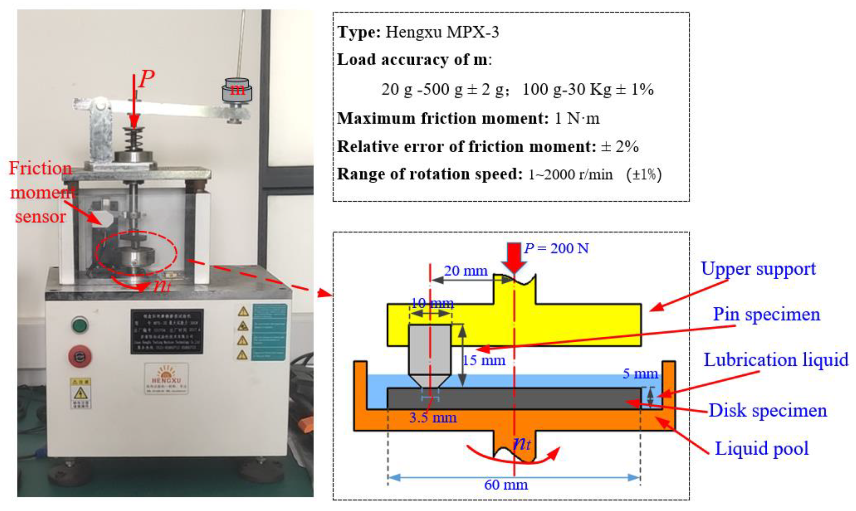
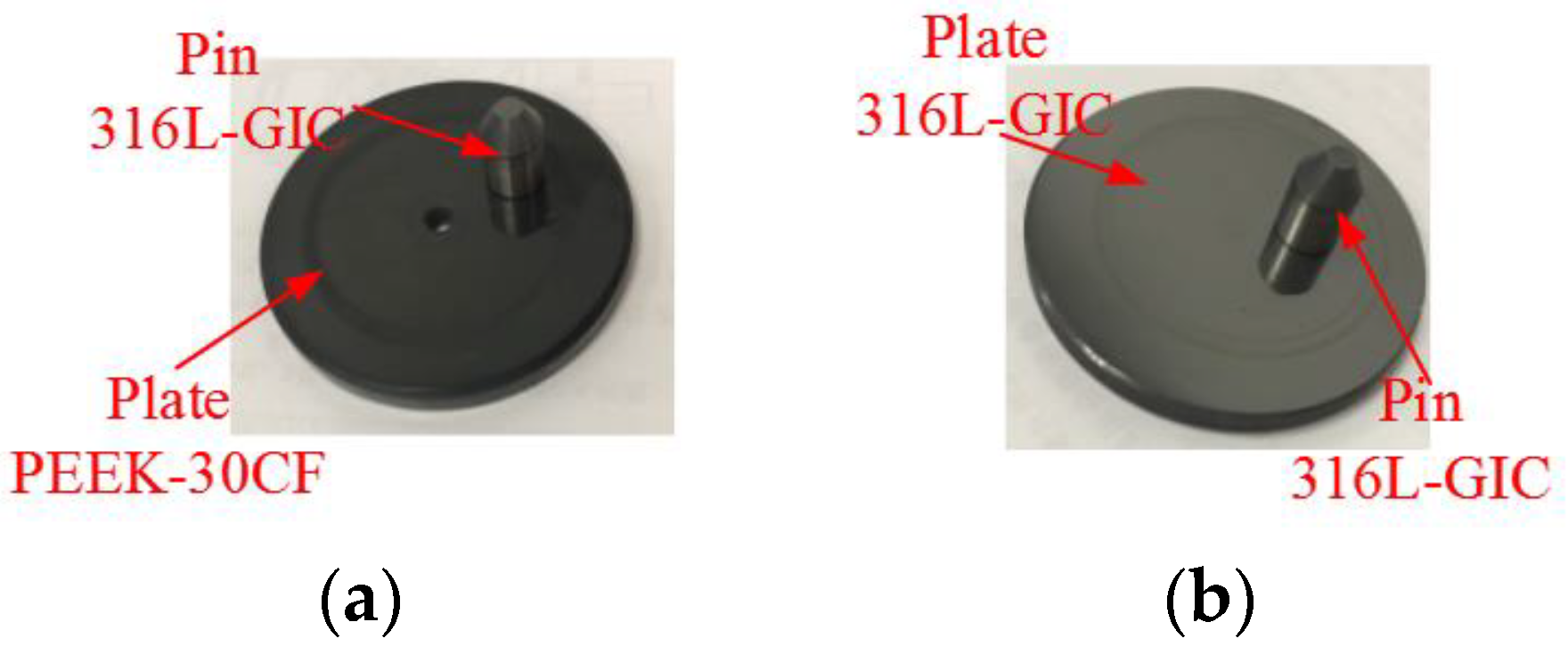
As shown by the friction test of different matching materials on the pin-disk friction machine (Figure 12) in reference [34], for a test speed of nt =15 rpm (corresponding to a linear velocity of 0.0314 m/s) with load P = 200 N (corresponding to a contact pressure of about 21 MPa for the friction pair), 316L-GIC (OVINO-graphite intercalated compound) /PEEK-30CF (polyetheretherketone reinforced with 30 per cent carbon fiber) has the optimal friction characteristics. This is followed by matching materials 316L-GIC/316L-GIC. The abrasion would be severe if both matching materials were made of stainless steel. According to the relative motion between the piston and cylinder as shown in Figure 3, friction coefficients at 15 rpm and 90 rpm (corresponding to a linear velocity of 0.1884 m/s) were analysed to reveal the friction performance of the two matching materials within the rotation scope of the HWBHM-SDV. The pin specimen and disk specimen for test are shown in Figure 13.
The friction test for each matching group will last for 10 h, while the abrasion and friction coefficient for each matching pair would be observed every 2 h to check the abrasion surface of specimens after friction. Thus, the specimens will be taken from the test machine, and then cleaned through an ultrasound cleaner and dried. During the test, specimens will be taken from the test machine every 2 h and then reinstalled on the test machine for the next test period. Thus, the reinstallation error would inevitably influence the surface contact of matching materials, which could also cause the discontinuity of CoF (coefficient of friction) between the end of the previous test period and the beginning of the subsequent test period. In this study, the influence of reinstallation error on matching pairs would not be considered.
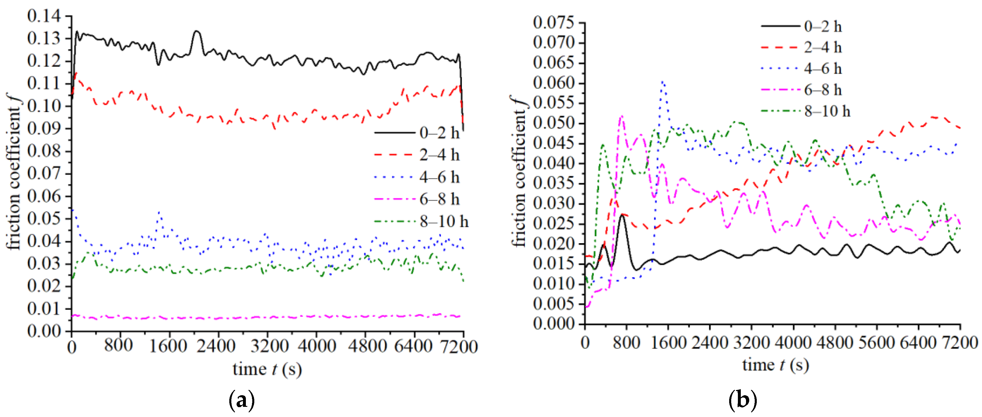
The friction coefficients of matching materials 316L-GIC and PEEK-30CF under different test speeds are shown in Figure 14. At 15 rpm (Figure 14a), the friction coefficient decreases with the increase of test time, and the friction coefficient reaches a stable value of 0.01 at 6 h to 8 h. At 8 h to 10 h, the friction coefficient is about 0.03. At 90 rpm (Figure 14b), the friction coefficient is smaller than that at 15 rpm, and the friction coefficient of 316L-GIC and PEEK-30CF is about 0.02 after an abrasion time of 6 h. The sharp increase in friction coefficient is caused by the centripetal effect, because of the insufficient lubrication of liquid at the touch surface between pin and disk specimen. It could be concluded that the increase of speed of relative motion between the friction pairs is conducive to enhanced lubrication, and could decrease the friction coefficient.
The friction coefficients of matching materials 316L-GIC and 316L-GIC under different test speeds are shown in Figure 15. At 15 rpm (Figure 15a), the friction coefficient of 316L-GIC is stable throughout the test, and the friction coefficient is about 0.065 after 10 h abrasion. At 90 rpm (Figure 15b), the friction coefficient is lowest from 0 h to 2 h, and then reaches a stable value of about 0.06. The sudden change in friction coefficient from 2 h to 4 h and 8 h to 10 h is mainly caused by the abnormal stopping and starting of the abrasion machine during the test.
Due to the running-in between the pin specimen and disk specimen being conducive to reducing the surface roughness of PEEK-30CF, the friction coefficient of hard-to-soft matching materials 316L-GIC and PEEK-30CF decreases over time at test speeds 15 rpm and 90 rpm, while for hard-to-hard matching materials 316L-GIC/316L-GIC, the friction coefficient is more stable during the 10 h abrasion test. The increased speed would increase the lubrication between the pin and disk specimens.

5. Influence of Factors on Leakage Performance of PSC Pair in HWBHM with SDV Based on Orthogonal Test

The analysis of friction coefficients for the two group matching materials shows that they all have good friction performance within the relative motion speed of the piston and swing cylinder. In addition to the abrasion performance, leakage performance is another important indicator. Especially under HWBHL lubrication, the leakage in friction pairs is always a severe problem. Many factors (such as structure parameters, working pressure, temperature, material properties, etc.) would affect the leakage in the PSC pair. There might exist complex interact effect among the factors [35,36]. To analysis the coupling influences of factors (including clearance, temperature, and working pressure) on leakage performance for the two kinds of matching materials as shown in Figure 16, the bidirectional fluid-structure coupling analysis is applied. Because the influence of working speed is very small, it will not be considered in this study.
To investigate the influence of fluid-structure interaction on leakage in a PSC pair, the method of fluid-structure coupling analysis was implemented through commercial software ANSYS 15.0. The simulation was conducted by the combination of a Fluent module and Transient Structure module. There are two pairs of coupling surfaces: one is the outside coupling surface on the lubrication film and coupling part on the cylinder, the other is inside the coupling surface on the lubrication film and coupling part on the piston. After repeated coupling calculations, the leakage δqhpc at the pressure outlet port for the lubrication film was recorded.
An orthogonal test was used to study the effects of the main influencing factors. The result can also provide guidance on the structural design of the PSC pair: based on the above analysis, clearance, temperature, and working pressure were selected as three test factors, and because each factor contains three levels, a type L9 (33) orthogonal test table was established (Table 3). The value of leakage in the clearance was calculated as shown in Table 4, where δqp is the leakage from a PSC pair with matching materials 316L-GIC/peek-30CF, and δqs is the leakage from a PSC pair with matching materials 316L-GIC/316L-GIC.
To determine the importance of factors affecting leakage, the averages of factors at each level and the ranges are shown in Table 5 where xqpi represents the mean of δqp for each factor at level i (i = 1, 2, 3), and Rqp represents the range of xqpi for each factor with matching materials 316L-GIC/PEEK-30CF. xqsi denotes the mean of δqs for each factor at level i (i = 1, 2, 3), and Rqs represents the range of xqsi for each factor with matching materials 316L-GIC/316L-GIC. The effect of factors will increase with the increase of Rqp or Rqs.
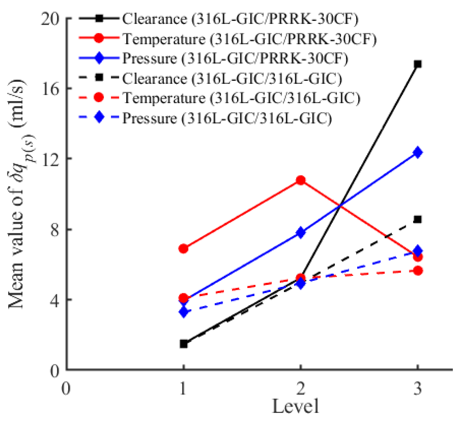
Thus, under the analysis of bi-direction fluid-structure coupling analysis, the degree of influence on Rqp(s) is: A > C > B for the matching materials 316L-GIC/316L-GIC and 316L-GIC/PEEK-30CF. To reflect the influence of each factor intuitively, the effects of all factors on means of δqp(s) for different matching materials are described in Figure 17. It can be concluded that the influence difference of clearance on leakage is not significant between matching materials 316L-GIC/316L-GIC and 316L-GIC/PEEK-30CF at Levels 1 and 2. The influence of pressure increases with the increase of clearance, causing larger deformation of materials with an increase of pressure. For the temperature, the difference between the two matching pairs is significant at low levels (T = 10 and T = 20), but the difference is not significant at Level 3 given the influence of pressure distribution under fluid-structure coupling analysis. For the influence of pressure, the difference between the two matching pairs increases with the increase of pressure.
During the operation of an HWBHM, there are about 2.5 PSC pairs under high pressure conditions, the theoretical volume efficiency loss ηhpv caused by PSC pairs can be expressed by Equation (6):
η h p v = 1 q × n 2.5 δ q h p + q × n
To compare the difference in volume efficiency loss between the calculation considering fluid-structure interaction analysis and theoretical analysis shown by Equation (7), parameter kct was established, where, ηhpvc is the volume efficiency loss caused by leakage δqhpc considering fluid-structure interaction:
{ k c t = ( η h p v c η h p v ) / η h p v η h p v c = 1 q × n 2.5 δ q h p c + q × n
Considering the influences of surface roughness and machining error, the clearance is set to be 10 μm in this analysis. With the assumption that the temperature of HWBHL is set to be constant at 20 °C, the deformation of structure caused by temperature is ignored.
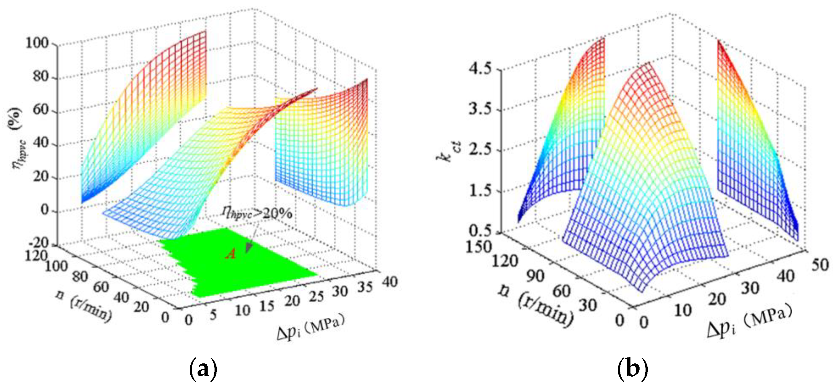
When considering the matching materials 316L-GIC and PEEK-30CF, the variation of volume efficiency loss and difference between fluid-structure interaction and theoretical analysis is shown in Figure 18. For matching materials 316L-GIC/PEEK-30CF, the volume efficiency loss could be very high when the working pressure exceeds 15 MPa, and the difference increases with the increase of working speed at working pressures exceeding 10 MPa and working speeds exceeding 30 rpm. In addition, the volume efficiency loss would increase by about 450 % at 100 rpm and a working pressure of 30 MPa, thus, limited by the material properties of matching materials, the maximum working pressure should be less than 15 MPa when the working speed is less than 100 rpm.
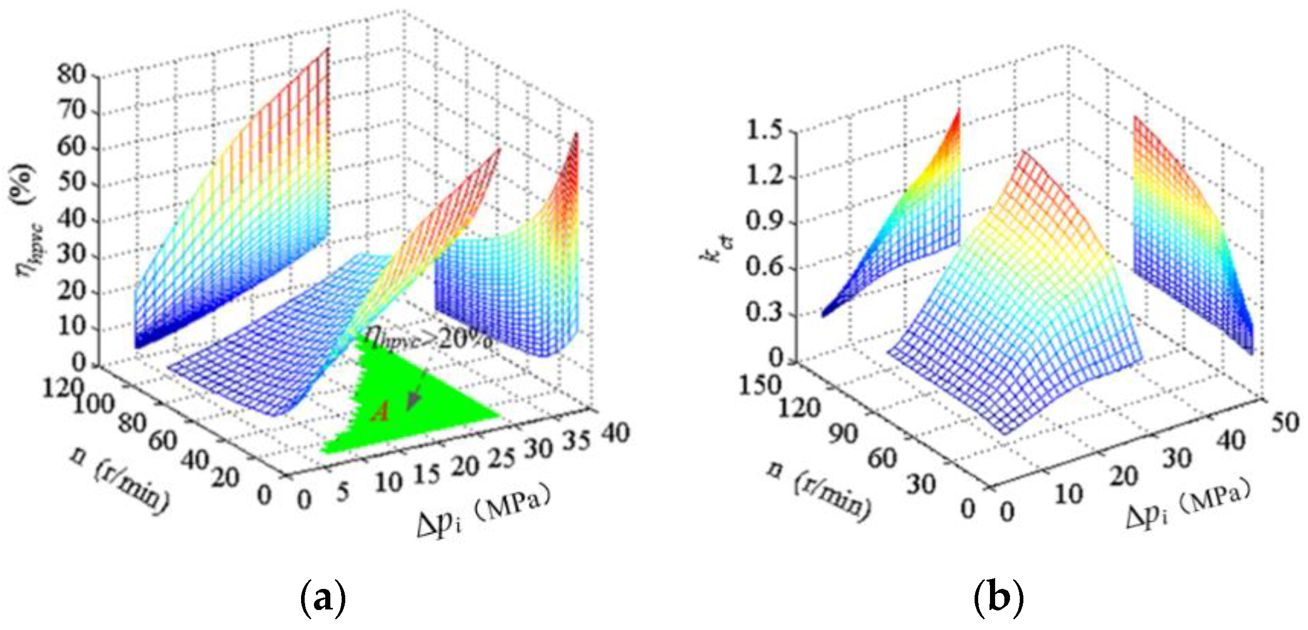
For matching materials 316L-GIC and 316L-GIC, the variation of volume efficiency loss, and difference between fluid-structure interaction and theoretical analysis are shown in Figure 19. For the small deformation of stainless steel, it can be seen that the working pressure should be limited to less than 28 MPa at a working speed of 100 rpm to obtain a high volume efficiency, while the working pressure should be limited to less than 20 MPa at a working speed of 40 rpm; however, the feasible scopes of working pressure and working speed are much wider than that of matching materials 316L-GIC and PEEK-30CF. Parameter kct increases with the increase of working pressure and working speed. The variation of kct is more stable under lower working speeds and lower working pressures. The volume efficiency loss will increase by more than 120% at a working pressure of 30 MPa and a working speed of 100 rpm.
To improve the working performance of PSC pair in the HWBHM-SDV, and improve the working scope of matching materials, an automatic compensation structure could be considered to compensate the clearance caused by structure deformation.

6. Conclusions

To reduce the leakage in traditional HWBHMs, an HWBHM with SDV distribution mechanism was proposed. In this research, to study the leakage and abrasion problems of a PSC pair in the proposed HWBHM-SDV, the friction performance of two matching materials within the working speed was tested, and the influences of factors on leakage performance considering fluid-structure interaction were studied by orthogonal test method. The following conclusions could be drawn:
  • Because the motion speed of PSC pair is very low when HWBHM-SDV is working within 0 to 100 rpm, the leakage from the PSC pair is mainly caused by pressure-gradient flow. The influence of seal length on leakage is insignificant at a seal length of 24 mm (Figure 4).
  • Within the working speed of 100 rpm, the matching materials 316L-GIC/PEEK-30CF and 316L-GIC/316L-GIC have good friction performance, the friction coefficient for 316L-GIC/PEEK-30CF is about 0.02 to 0.04, and the friction coefficient for 316L-GIC/316L-GIC is about 0.05 to 0.07. The friction coefficient of 316L-GIC/316L-GIC is much more stable than that of 316L-GIC/PEEK-30CF.
  • Based on the orthogonal test, it can be concluded that when considering the influence of bi-directional coupling of lubrication film and structure, clearance has the most significant influence on leakage, followed by pressure and temperature. The difference in leakage between matching materials 316L-GIC/316L-GIC and 316L-GIC/PEEK-30CF is insignificant when the clearance is less than 8 μm and at a working pressure of less than 10 MPa.
  • With a clearance of 10 μm at a temperature 20 °C, the operating scopes of working speed and working pressure are significantly influenced by the matching materials used in the PSC pair. For the soft-to-hard matching materials 316L-GIC with PEEK-30CF, the range of application is small: the working pressure should be less than 15 MPa to ensure a higher volume efficiency loss. For hard-to-hard matching materials 316L-GIC with 316L-GIC, the working scope is much wider than matching materials 316L-GIC with PEEK-30CF: the working pressure can be as high as 28 MPa when the working speed exceeds 80 rpm. Besides, for the two groups of matching materials, the rate of change of the ratio in volume efficiency loss caused by fluid-structure interaction increases with the increases in working pressure and working speed.

Author Contributions

Conceptualization, J.Z. and B.Q.; methodology, J.Z. and B.Q.; software, B.Q.; validation, J.Z., B.Q. and J.M.; formal analysis, B.Q. and J.M.; investigation, B.Q. and J.M.; resources, B.Q.; data curation, J.Z., B.Q.; writing—original draft preparation, B.Q.; writing—review and editing, B.Q.; visualization, B.Q. and J.M.; supervision, J.Z.; project administration, J.Z.; funding acquisition, J.Z. All authors have read and agreed to the published version of the manuscript.

Funding

This research was funded by the National Science Foundation of China, grant number 51675519.

Conflicts of Interest

The authors declare no conflict of interest.

Abbreviation

[C]the specific heat capacity of high water-based hydraulic liquid
[d]the diameter of piston
[d0]the diameter of pin specimen
[d1]the contact diameter between pin specimen and disk specimen
[d2]the diameter of disk specimen
[e0]the distance between O and O1
[Ehp]power loss caused by pressure-gradient flow
[Fp1]the hydraulic force upon valve
[Fp2]the hydraulic force under valve
[FN0]the support force from valve seat
[Ft]the spring force
[h1]the height of pin specimen
[h2]the height of disk specimen
[hp]the annular clearance of PSC pair
[kct]the difference between volume efficiency loss caused by fluid structure interaction and theoretical calculation
[li]the distance of O1 and O2
[lp]the total length of piston
[n]the rotation speed of HWBHM
[nt]the rotation speed of plate specimen
[O]the rotation center of crankshaft
[O1]eccentric distance of eccentric structure on crankshaft
[O2]the rotation center of cylinder
[P]the load applied on pin specimen and plate specimen
[q]the designed displacement of HWBHM
[rf]the average friction radius
[R0]the distance of O and O2
[Rqs]the range of xqsi for each factor with matching materials 316L-GIC/316L-GIC
[Rqp]the range of xqpi for each factor with matching materials 316L-GIC/PEEK-30CF
[vi]the maximum value of relative velocity between piston and cylinder
[xqpi]the mean of δqp for each factor at level i (i = 1, 2, 3)
[xqsi]the mean of δqs for each factor at level i (i = 1, 2, 3)
[ρ]the density of high water based hydraulic liquid
[μ]the dynamic viscosity of high water-based hydraulic liquid
[θi]the rotation angle of cylinder
[φi]the rotation angle of crankshaft
[ω]the rotation speed of crankshaft
[δlp]the seal length for piston and swiveling cylinder
[δqhp]the leakage caused by the pressure in PSC pair
[δqp]the leakage in PSC pair caused by fluid-structure interaction with materials 316L-GIC/PEEK-30CF
[δqs]the leakage in PSC pair caused by fluid-structure interaction with materials 316L-GIC/316l-GIC
[δqτ]the leakage caused by shear flow in PSC clearance
pi]the differential pressure of clearance in PSC pair
Tp]the temperature raise caused by energy loss Ehp
hpv]the volume efficiency loss caused by PSC pairs based on theoretical analysis
hpvc]the volume efficiency loss caused by fluid-structure interaction

References

  1. Striker, S. Advances make tap water hydraulics more practical. Hydraul. Pneum. 1996, 49, 29–32. [Google Scholar] [CrossRef]
  2. Conrad, F. Why use tap water hydraulic systems? It’s a natural approach. In Proceedings of the International Workshop on Water Hydraulic Systems and Applications, Lyngby, Denmark, 3–4 September 1998. [Google Scholar]
  3. Conrad, F.; Hibrecht, B.; Jepsen, H. Design of low-pressure and high-pressure tap water hydraulic systems for various industrial applications. SAE Trans. 2000, 109, 316–330. [Google Scholar]
  4. Liu, Y.S. Applications of seawater hydraulics in deep-sea equipment. Chin. J. Mech. Eng. 2014, 50, 28–35. [Google Scholar] [CrossRef]
  5. Westinghouse, E.C.; Oceanoc, D. Development of a Seawater Hydraulic Vane Motor for Driver Tools; Civil Engineering Laboratory Naval Construction Battalion Center: Port Hueneme, CA, USA, 1980; pp. 1–119. [Google Scholar]
  6. Wolfhart Industires. Seawater Hydraulic Motor and High Pressure Water Pump. Available online: http://www.wolfhartindustries.com/wolfhart.htm (accessed on 15 April 2020).
  7. Water Hydraulics. Water Hydraulics Janus Motor. Available online: http://www.waterhydraulics.co.uk/new/PDF/motors.pdf (accessed on 15 April 2020).
  8. HytarOy. HytarOy APM. Available online: http://www.hytar.fi/sites/default/files/pdf/apm_datasheet_0 (accessed on 15 December 2019).
  9. Tsukagoshi, H.; Nozaki, S.; Kitagawa, A. Versatile water hydraulic motor by tap water. In Proceedings of the 2000 IEEE/RSJ International Conference on Intelligent Robots and Systems, Takamatsu, Japan, 31 October–5 November 2000; Volume 3, pp. 1949–1954. [Google Scholar] [CrossRef]
  10. Shinoda, M.; Yamashina, C.; Miyakawa, S. Development of low-pressure water hydraulic motor. In Proceedings of the Sixth Scandinavian International Conference on Fluid Power, Tampere, Finland, 26–28 May 1999; pp. 243–254. [Google Scholar] [CrossRef] [Green Version]
  11. Nie, S.L. SEWHAPM: Development of a water hydraulic axial piston motor for underwater tool systems. Proc. Inst. Mech. Eng. Part C J. Mech. Eng. Sci. 2005, 219, 639–656. [Google Scholar] [CrossRef]
  12. Shigeru, H. Takuya. Investigation for output torque of a low pressure water hydraulic planetary gear motor. Vonda Hidravl. 2012, 18, 26–35. [Google Scholar]
  13. Manring, N.D. Valve-plate design for an axial piston pump operating at low displacements. ASME J. Mech. Des. 2003, 125, 200–205. [Google Scholar] [CrossRef]
  14. Seeniraj, G.K.; Ivantysynova, M. Impact of valve plate design on noise, volumetric efficiency and control effort in an axial piston pump. In Proceedings of the ASME 2006 International Mechanical Engineering Congress and Exposition, Fluid Power Systems and Technology, Chicago, IL, USA, 5–10 November 2006; pp. 77–84. [Google Scholar] [CrossRef]
  15. Wang, S. Improving the volumetric efficiency of axial piston pump. ASME J. Mech. Des. 2012, 134, 111001. [Google Scholar] [CrossRef]
  16. Yang, L.J. Numerical and experimental investigation on torque characteristics of seawater hydraulic axial piston motor for underwater tool system. Ocean. Eng. 2015, 104, 168–184. [Google Scholar] [CrossRef]
  17. Wang, Z.Q.; Gao, D.R.; Fei, J.H. Analysis and numerical simulation of leakage flow speed high torque water hydraulic motor’s plain flow distribution pair. Appl. Mech. Mater. 2012, 233, 204–207. [Google Scholar] [CrossRef]
  18. Sliwiński, P. Flow of liquid in flat gaps of the satellite motor working mechanism. Pol. Marit. Res. 2014, 21, 50–57. [Google Scholar] [CrossRef] [Green Version]
  19. Qiu, B.J.; Zhao, J.Y.; Zhao, L. Characterization and performance analysis of a new type of a high water-based hydraulic motor with a self-balanced distribution valve mode. Proc. Inst. Mech. Eng. Part C J. Mech. Eng. Sci. 2017, 231, 4655–4669. [Google Scholar] [CrossRef]
  20. Wang, C.; Han, S.S.; Li, K.; Chen, L.X. Study on leakage characteristics of friction pairs in construction machinery remanufacturing piston motor. Mach. Tools Hydraul. 2018, 46, 83–85. [Google Scholar] [CrossRef]
  21. Olsson, H.; Ukonsaari, J. Wear test and specification of hydraulic fluid in industrial applications. Tribol. Int. 2003, 36, 835–841. [Google Scholar] [CrossRef]
  22. Huang, G.Q.; He, X.F.; Zhu, Y.Q. Analysis on optimal clearance of piston friction pair and its influence factors for water hydraulic pump. Chin. Mech. Eng. 2011, 22, 1668–1672. [Google Scholar] [CrossRef] [Green Version]
  23. Huang, G.Q.; Yu, J.; Pu, H.L. Optimal design on clearance of piston friction pair for water hydraulic pump. Adv. Mater. Res. 2011, 287, 3056–3060. [Google Scholar] [CrossRef]
  24. Cao, W.B.; Dong, J.C. Stress and wear leakage analysis of piston in hydraulic axial piston pump. J. Gansu Sci. 2018, 30, 103–107. [Google Scholar] [CrossRef]
  25. Yang, H.Y.; Yang, J.; Zhou, H. Research on materials of piston and cylinder of water hydraulic pump. Ind. Lubr. Tribol. 2003, 55, 38–43. [Google Scholar] [CrossRef]
  26. Liu, Y.S.; Wu, D.F.; Wu, X.F. Material screening of matching pairs in a water hydraulic piston pump. Ind. Lubr. Tribol. 2009, 61, 173–178. [Google Scholar] [CrossRef]
  27. Dong, W.T.; Nie, S.L.; Zhang, A.Q. Tribological behavior of PEEK filled with CF/PTFE/graphite sliding against stainless steel surface under water lubrication. Proc. Inst. Mech. Eng. Part J J. Eng. Tribol. 2013, 227, 1129–1137. [Google Scholar] [CrossRef]
  28. Zhang, A.Q.; Nie, S.L.; Yang, L.J. Evaluation of tribological properties on PEEK + CA30 sliding against 17-4PH for water hydraulic axial piston motor. Proc. Inst. Mech. Eng. Part C J. Mech. Eng. Sci. 2014, 228, 2253–2265. [Google Scholar] [CrossRef]
  29. Ernst, M.H.; Ivantysynova, M. Cylinder bore micro-surface shaping for high pressure axial piston machine operation using water as hydraulic fluid. In Proceedings of the ASME/BATH 2017 Symposium on Fluid Power and Motion Control (FPMC 2017), Sarasota, FL, USA, 16–19 October 2017; p. 20180204625600. [Google Scholar] [CrossRef]
  30. Ernst, M.H.; Ivantysynova, M. Micro surface shaping for the high-pressure operation of piston machines with water as a working fluid. In Proceedings of the ASME/BATH 2015 Symposium on Fluid Power and Motion Control (FPMC 2015), Chicago, IL, USA, 12–14 October 2015; p. 20161702302083. [Google Scholar] [CrossRef]
  31. Yang, Z. The analysis of piston-barrel leakage in a superhigh pressure water hydraulic piston pump. Hydromechatron. Eng. 2012, 40, 39–42. [Google Scholar] [CrossRef]
  32. Gary, W.K.; Chua Patrick, S.K. Water hydraulics-theory and applications 2004. workshop on water hydraulics. In Proceedings of the Agricultural Equipment Technology Conference (AETC’04), Louisville, Kentucky, 8–10 February 2004; pp. 1–33. [Google Scholar]
  33. Ma, Q.F. Handbook of Practical Thermophysical Properties; China Agricultural Machinery Press: Beijing, China, 1986; p. 809. ISBN 15216.141. (In Chinese) [Google Scholar]
  34. Qiu, B.J.; Zhao, J.Y.; Man, J.X. Comparative study of materials for friction pairs in a new high water-based hydraulic motor with low speed and high pressure. Ind. Lubr. Tribol. 2019, 71, 164–172. [Google Scholar] [CrossRef]
  35. Shang, L.Z.; Ivantysynova, M. A temperature adaptive piston design for swash plate type axial piston machines. Int. J. Fluid Power 2017, 18, 38–48. [Google Scholar] [CrossRef]
  36. Mizell, D.; Ivantysynova, M. Material combinations for the piston-cylinder interface of axial piston machines: A simulation study. In Proceedings of the 8th FPNI Ph.D Symposium on Fluid Power (FPNI 2014), Lappeenranta, Finland, 11–13 June 2014; p. 20144900271287. [Google Scholar] [CrossRef]
Figure 1. Schematic diagram of configuration of a high water-based hydraulic motor (HWBHM) with a self-balanced distribution valve (SDV). (a) The schematic diagram of the HWBHM with SDV, (b) The schematic of driving structure, (c) The schematic of distribution structure; 1-crankshaft, 2-thrust bearing, 3-outer shell, 4-swiveling cylinder, 5-piston, 6-inner shell,.7-distribution block, 8-inlet distribution valve (I-DV), 9-outlet distribution valve (O-DV), 10-end cover, 11-distribution crankshaft, 12-distribution bearing, A-inlet port, B-outlet port.
Energies 13 03175 g001
Figure 2. Schematic of a piston-swivelling-cylinder (PSC) pair in HWBHM with SDV: (a) Basic structure of the PSC pair; (b) PSC pair at an arbitrary position; (c) PSC pair at position φi = 0.
Energies 13 03175 g002
Figure 3. Variation of vi with φi.
Energies 13 03175 g003
Figure 4. Variations of δqhppi with sealing length under the maximum clearance of fit tolerance in common use.
Energies 13 03175 g004
Figure 5. Variations of δqhppi with high accuracy fit tolerance at sealing length δlp = 24 mm.
Energies 13 03175 g005
Figure 6. Variation of leakage δqτ with rotation speed n and angular position φi of the crankshaft.
Energies 13 03175 g006
Figure 7. The variations of temperature raise ΔTp with parameters (ρ, C) = (103 Kg/m3, 4.2 × 10³ J/(Kg. °C)).
Energies 13 03175 g007
Figure 8. Interaction of pressure distribution and clearance size in a PSC pair.
Energies 13 03175 g008
Figure 9. Fluid-structure interaction simulation of ¼-scale model for the PSC pair.
Energies 13 03175 g009
Figure 10. Influences of layer grid’s number and pressure on leakage difference between simulation result and theoretical result.
Energies 13 03175 g010
Figure 11. The pressure distribution of lubrication result and deformations of structures in the PSC pair: (a) pressure distribution in the lubrication film; (b) deformation of the coupling part on the piston; (c) deformation of the cylinder.
Energies 13 03175 g011
Figure 12. Schematic diagram of pin-disk friction abrasion machine.
Energies 13 03175 g012
Figure 13. Two groups of matching materials for friction test: (a) 316L-GIC with PEEK-30CF; (b) 316L-GIC with 316L-GIC.
Energies 13 03175 g013
Figure 14. Friction coefficient of 316L-GIC with PEEK-30CF under different test speed: (a) Variation curve of friction coefficient under 15 r/min; (b) Variation curve of friction coefficient under 90 r/min.
Energies 13 03175 g014
Figure 15. Friction coefficient of 316L-GIC with 316L-GIC under different test speeds: (a) Variation curve of friction coefficient at 15 r/min; (b) Variation curve of friction coefficient at 90 r/min.
Energies 13 03175 g015
Figure 16. The structures of the PSC pair with different matching materials: (a) PSC pair with 316L-GIC and PEEK-30CF; (b) PSC pair with 316L-GIC and 316L-GIC.
Energies 13 03175 g016
Figure 17. Influence of factors on leakage.
Energies 13 03175 g017
Figure 18. The variations of volume efficiency loss and parameter kct for matching materials 316L-GIC and PEEK-30CF with consideration of fluid-structure interaction: (a) The variation of volume efficiency loss; (b) The variation of kct.
Energies 13 03175 g018
Figure 19. The variations of volume efficiency loss and parameter kct for matching materials 316L-GIC and 316L-GIC with consideration of fluid-structure interaction: (a) the variation of efficiency loss with consideration of the fluid-structure interaction; (b) the difference between coupling analysis and theoretical analysis.
Energies 13 03175 g019
Table 1. Basic parameters of main structures in designed HWBHM with SDV.
ParameterValue
diameter of piston: d (mm)40
eccentric of crankshaft: e0 (mm)15
diameter of eccentric structure on crankshaft: R (mm)45
distance of O and O2: R0 (mm)90
designed clearance: r (mm)5
thickness of piston slipper: δl2 (mm)3.8
total length of piston: lp (mm)65.6
Table 2. Relation of dynamic viscosity and temperature for water.
ParameterValue
T (°C)10203040
μ (×10−3 Pa·s)1.3061.0060.8050.659
Table 3. The design of the orthogonal test.
LevelA Clearance (μm)B Temperature (°C)C Pressure (MPa)
151010
282020
3104030
Table 4. Orthogonal experimental table for type L9 (33).
GroupABCδqp (mL/s)δqs (mL/s)
1510100.468681800.46468416
2520201.205739921.19679212
3540302.842619122.76074932
4810305.625559605.37024000
5820102.495256002.36276800
6840207.59242287.15616000
710102014.6056806.46020000
810203028.64092012.1094800
91040108.85992007.04848000
Table 5. Range analysis for δqp and δqs.
FactorABC
xqp11.5056800006.8999738003.941285933
xqp25.23774613310.780638647.801280907
xqp317.368840006.43165397312.36969957
Rqp15.863159724.3489846678.428413640
xqs11.4740750004.0983747203.291977387
xqs24.9630560005.2230133734.937717373
xqs38.5393866675.6551297736.746823107
Rqs7.0653116671.5567550533.454845720