Article

A Bidirectional Electrical Vehicle Charger and Grid Interface for Grid Voltage Dip Mitigation

Department of Energy Engineering, German Jordanian University, Amman 11180, Jordan
*
Author to whom correspondence should be addressed.
Energies 2020, 13(15), 3784; https://doi.org/10.3390/en13153784
Submission received: 25 May 2020 / Revised: 19 July 2020 / Accepted: 21 July 2020 / Published: 23 July 2020
(This article belongs to the Section E: Electric Vehicles)

Abstract

:
Power quality issues have recently become a source of major concern due to the large increase in load demand and the addition of various sources of disturbance at the distribution level. Power quality mainly refers to voltage quality. Sudden load variations can lead to a fall in the line voltage magnitude, creating what is called a voltage sag. Many solutions have been proposed and implemented for voltage sag compensation. Power electronics-based solutions such as grid-connected converters and AC/DC schemes are considered basic units for transient voltage fault ride-through capability. This paper describes a multifunctional intelligent bidirectional electrical vehicle (EV) charger that is able to charge the EV battery at different power ratings in addition to voltage sag compensation. The performance of the proposed system is verified and validated through MATLAB/Simulink simulations (R2020A). The proposed solution can effectively meet three main requirements: charging the EV battery at different power ratings, detecting the voltage sag event, and providing the required active and reactive power compensation for voltage sag compensation.

1. Introduction

Electric vehicles (EVs) have proven to be a feasible solution to meet emission regulations that are driven by environmental concerns. Moreover, they provide the capability to fulfill any power grid storage needs by transferring power from connected vehicles to the grid [1]. The increased market penetration of EVs, the recent advances in energy storage technologies, the power conversion capability of power electronics and the need to produce and deliver energy more efficiently are enabling factors leading to the exponential growth of EVs in the transportation sector.
“Smart Grid” is a term used to define an electric grid that has increased intelligence. It envisions upgrading and expanding the current electrical grid in order to accommodate renewable resources and microgrids and more penetration of information technology enabling real time digital control of energy sources and current flow based on actual data. It is therefore an enabler of system-wide solutions in the areas of network operations, asset management, distributed generation management, advanced metering, enterprise data access and public and private transportation [2]. However, these system-wide solutions can only be achieved by smart integration of renewable energy systems, distributed generation, storage and demand side integration. Therefore, designing a smart grid compatible with EVs is one of the main goals of the transportation industry [2].
Vehicle-to-grid (V2G) is becoming a mainstream concept that can be utilized to support the power grid. It can provide several ancillary services such as peak power shaving and spinning reserves, in addition to voltage and frequency regulation. The most beneficial feature of V2G technology for voltage regulation is its capability to respond to grid disturbances in a very short time. This is possible as EVs are coupled to the grid through power electronics interfaces, which enables a fast response in the order of milliseconds.
Short duration voltage disturbance (voltage sag, swell and interruption), long duration voltage disturbances (over-voltage and under-voltage), harmonics, voltage unbalance and voltage flicker are the major power quality issues at the distribution level. Developing a system that can provide a fast response and accurate compensation in order to reduce these problems is becoming possible with the recent advancements in power electronic devices and energy storage units.
The distribution system frequently suffers from voltage sag, which is defined as a drop in RMS voltage magnitude between 0.1 and 0.9 per unit (P.U.) for a short duration of time, which ranges between 0.5 cycles and one minute. It is mainly caused by faults on adjacent feeders, variation in the load conditions, lightning or induction motor starting [3].
It is essential to compensate the voltage sag by either the injection of reactive current or a series voltage with the line. In order to improve the compensation capability, an energy storage unit is essential to supply the power during the voltage compensation. In this research, the focus will be on using a power electronic-based circuit with an EV battery as a source to compensate voltage sags.
Over the past decade, research on voltage sag compensation, grid connected converters and control strategies have advanced the state of the art. The authors in [4] proposed a new configuration for the grid connected converter (GCC). This configuration enables the GCC to be connected either in parallel or in series according to defined modes of operation. The controller will use measured line voltage and current to trigger switches accordingly to engage the suitable operating mode. The same authors in [5] propose a shunt-series switched GCC to mitigate voltage sag and swell. It was shown that this configuration has superior performance in reducing the effect of the unbalanced sag problem. Both these papers deal with the converters, but not the energy source or overall system integration scheme.
In [6] the authors used a hybrid control strategy to obtain the reference reactive power values and power reference set-points that are sent from the management system to control the active power injection, where the effect of voltage sag was decreased using reactive power control in a small distribution system.
The authors in [7] proposed a grid voltage sag control strategy that uses traditional dual voltage and current loop control, based on the sag depth for the positive sequence of grid voltage, while the authors in [8] proposed a voltage regulation reactive power control of the GCC when connected to an EV for voltage regulation. This control sends active power commands to charge the EV when there is no sag, while when a sag is detected, it determines the optimal angle of compensation according to the sag depth. The authors in [9] proposed advanced control for a PV plant that has the ability to ride through balanced and unbalanced faults, ensuring that the system stays connected. A controller based on a positive sinusoidal sequence regulator (PSSR) was used with fuzzy logic in a series active filter for load voltage compensation in [10]. The PSSR was used to eliminate control error when the fundamental voltage is calculated by the fuzzy logic based controller. The authors in [11] addressed the use of an EV battery in a bidirectional charging system for voltage regulation during transients using the conventional double closed control with a PI fuzzy controller.
EVs may be considered as energy sources that are able to provide many benefits to the grid under the V2G concept as long as the support infrastructure exists and proper control is implemented. One important enabling component is the EV bidirectional battery charger. With bidirectional functionality, the battery charger performs several functions in addition to the charging operation. Much research has proposed a variety of bidirectional topologies, algorithms, control strategies, battery modeling, charging and discharging methodologies for EV battery chargers as a distributed energy source.
The authors in [12] conducted a review regarding three aspects: GCC topologies, the battery energy storage system, and V2G applications and their benefits for grid support. The main challenges in each of these three aspects were illustrated. The bidirectional topologies that enable EVs to discharge providing grid support, battery technologies, and charger design have been reviewed by the authors of [13], considering the effect of EVs on the power system stability and how they can impact the power system parameters. As the EV charger is a nonlinear power electronic equipment, a power quality characterization of EV chargers was performed by the authors in [14] through an effective control system that responds to adverse impacts on the power quality of the grid.
The authors in [1] addressed the capability for reactive power support using off-board charger stations, considering the limitations of line current harmonic contents and the battery charging current. The controller uses two outer control loops to track the active and reactive power commands, which results in reference values for active and reactive current. Two inner loops are used to compare these reference values with actual line current. In [15] the authors examined a single phase on-board charger topology with its control for reactive power support, which was able to charge the battery while providing reactive power support. This was done without degrading the lifetime of the battery. In [16] the authors focused on a three phase on-board charger with bidirectional capability for reactive power compensation, in which the charging profiles were obtained experimentally to examine the reactive power support capability during charging.
Finally, in [6] the authors used a hybrid control strategy of the droop method to get the reference reactive power values and power reference set points sent from the management system to control active power injection, whereby the effect of voltage sag was decreased using reactive power control in the system, which consisted of a plug-in hybrid electric vehicle (PHEV), grid, house and power management system.
The authors in [17] proposed a coordinated control strategy in a fast charging station equipped with a flywheel energy storage system, which is able to charge electric vehicles and give active and reactive power support to the grid when requested. This control method is based on distributed bus signaling (DBS) so the communication between the charging station and the grid operator can be avoided.
The authors in [18] proposed an energy management scheme (EMS) that employs an off-board EV smart charger to charge the EV, which also supports the grid during short-term variance of renewables and voltage regulation by means of reactive power compensation for shallow voltage sags and swells and achieved the goal of the aggregating the EVs at the charger level to support the grid. A controllable EV charger is designed and tested by the authors in [19] that enables charging and discharging at different power levels provided by the EV’s EMS, through which numerous benefits can be obtained for both consumers and the electric grid.
The authors in [20] presented a sag compensation system based on a dynamic voltage restorer (DVR) that injects a series voltage in order to investigate the possibility of exploiting battery electric vehicles (BEV) or PHEVs for grid ancillary services, particularly voltage sag compensation based on the concept of V2G, showing that the compensation service can be considered sustainable if the requested amount of power is less than the capacity of the EV battery.
The deployment of battery technologies is becoming more significant with the recent advancement in battery technologies and with the increased utilization of batteries in various technologies such as renewables, EVs and portable electronic devices. EVs are expected to grow rapidly in the near future as they offer the most popular alternative energy option in the reduction of oil consumption.
Battery modelling serves as a basis for efficient design and control, so it is important to establish an accurate battery model to represent the characteristics of the EV battery. EV batteries have complex charging and discharging characteristics, and there are many factors that affect their performance. In order to accurately predict the performance of batteries, there are three ways to model the EV battery that differ in objectives and complexity: the electrochemical based model, the thermal based model, and the electric circuit-based model.
Electrochemical-based models are suitable for battery design purpose and are very accurate in representing the electrochemical processes occurring in batteries. These models require a variety of cell parameters and complex numerical computational methods that need in-depth knowledge of the battery chemical structure and properties [21]. Although high accuracy can be achieved using these models, they are unsuitable to use in simulations where the electrical terminal behavior of the battery and the state of charge (SOC) need to be determined with reasonable computing times.
Recently, thermal based models have gained researchers’ interest due to the increased use of Li-ion batteries in EVs, so understanding the thermal behavior of Li-ion batteries is essential for both the battery operating life requirements and safety considerations [21]. The authors in [22] proposed a novel battery charging control strategy based on a newly developed coupled thermoelectric model that applies the constrained generalized predictive control to maintain the battery health and longer lifetime while fast charging without causing temperature rise during charging, while the authors in [23] attempted to improve battery performance by enabling effective self-heating for Li-ion batteries at low temperatures. However, these models are also characterized by many parameters and complex calculations.
Electric circuit-based models are used to describe the electrical performance of the EV battery by using equivalent circuits composed of passive components such as resistors and capacitors, possibly inductors and a voltage source. Therefore, they are particularly suitable and can be easily incorporated into circuit simulations [21]. The accuracy that is achievable with these models can be maximized by modifying these models to address the dynamic behavior by adding the effects of, for example, state of health (SOH), temperature and capacity fading on battery output characteristics.
Among all the models, the electric circuit-based Shepherd’s model is used in this study; it is represented by a controlled voltage source in series with internal resistance.
It is important to establish charging and discharging methodology to control and regulate power transfer between the EV and the grid and that can be possible by utilizing battery current as a control parameter. DC/DC converter control is very straightforward as this controller operates at DC quantities, so zero steady state error and fast response can be achieved.
Among various charging strategies, the combined constant current constant voltage (CC–CV) control strategy is commonly used for Li-ion batteries, and it is suitable for fast charging, as it enables complete charging without overcharging [24]. An alternative to the conventional CC–CV method, is the multistage constant current (MSCC) charge method for fast charging along with higher charge efficiency and an increased life cycle of the battery compared to the CC–CV method [25]. MSCC is composed of several CC mode stages with different amplitudes, so the method for selecting the current amplitude at each stage is very important, as it would affect its performance. Hence, finding the optimal charge pattern (OCP) in order to optimize the charge performance with the MSCC charge method is essential [24,25]. The constant current–constant voltage (CC–CV) and multistage (CC–CV) charging strategies are optimized in [26] by finding the optimal tuning parameters for CC–CV and MCC–CV charging patterns to ensure a healthy, efficient fast charging of Li-ion batteries. The authors in [27] proposed a novel multi-objective optimization framework to optimize the multistage constant-current (MCC) charging profile of the Li-ion battery to achieve economic fast charging for Li-ion batteries.
The current research in literature addresses converters, converter control, EV charging or sag compensation, but none deal with a complete system. In this paper, a complete system that detects the sag event, determines the compensation energy requirement, evaluates if enough energy from willing grid-connected EVs is available and initiates one of several compensation techniques based on the above information. The system may even continue charging vehicles during compensation under certain scenarios.
The core theme of the work presented in this paper is that even though research on individual components or circuits is extremely valuable to the advancement of the collective knowledge in literature, application-based system integration is just as important. Designing a voltage sag detection technique that does not determine required mitigation energy, a bidirectional charger that does not consider individual V2G user participation preferences or a system controller that cannot distinguish between different reactive power needs are not applicable in such practical applications. The overall system operational requirements are set, and the individual components and subsystems are tailored to meet the system’s objective, while being scalable and repeatable.

2. System Configuration

2.1. System Topology

The proposed topology is based on a V2G application, which is applied to an off-board DC fast charging infrastructure. The capability of the AC/DC converters usually used in V2G applications is not enough to support the grid when it is shunt connected, due to the limited power and current ratings [4]. Thus, the proposed topology enables the connection in either parallel or a series configuration, according to grid conditions. The complete circuit of the proposed topology for the V2G battery intelligent charger is shown in Figure 1. The power circuit is composed of the power grid, the load and two converter stages. The converter stages consist of a shunt converter whose input voltage is filtered by a third-order LCL filter and a series converter and whose input voltage is filtered by a second-order LC filter. These two converters share the same DC-link capacitor and are connected to an EV battery through the DC/DC converter.
The control system consists of three main sub-controllers. (1) A bidirectional AC/DC converter controller to charge the EV battery, provide reactive power support whenever a small voltage sag is detected and respond to any reactive power request. (2) A series AC/DC converter controller that only operates if there is a need to introduce a series voltage when a deep voltage sag is detected. (3) A DC/DC converter controller that controls both the charging and the discharging of the EV battery.
The controllers generate the necessary switching pattern to satisfy the objective of the proposed topology, to provide or consume active and reactive power, serving both grid-to-vehicle (G2V) and V2G applications. To accomplish this, two bypass switches, S1 and S2, are used to enable the connection of either the shunt or the series converter.
In a practical application, several EVs will be connected to the system. Each EV will be connected to its own DC/DC converter for charging, and the DC link is the coupling point between the different EV chargers and the shunt/series converters. Single EVs may choose to participate or not in the intervention, but if any EV is willing to participate, then it will contribute to the DC link and not the sag directly. The system level controller will decide, based on available energy and sag mitigation requirements, which converter (series/shunt) to initiate, which is independent of the EV charging circuit. There is decoupling between the individual chargers and the sag mitigation hardware.

2.2. System Operation

In order to control the off-board EV battery charger effectively, the operation of the proposed topology should be well defined. The DC off-board charger, shown previously in Figure 1, is designed to meet the bidirectional active and reactive power exchange requirements, in addition to the EV battery charge requirements.
Since the EV battery charger does not directly interact with the grid, an algorithm that decides the charging and discharging modes of operation for the EV battery charger is needed, which is done by the local controller. It has to combine the previous individual controls in such a way that the power electronic interface is capable of charging the EV and can effectively utilize the EV battery to provide active and reactive power support for voltage sag mitigation. It should be noted that in this study, a small voltage sag is defined as system voltage that is between 85–90% of its nominal value, while a deep voltage sag is between 30–85%.
As shown in Figure 2, two AC/DC converters share the same DC-link capacitor, which is sufficiently sized for reactive power operation even when the EV battery is not connected, enabling the stationary charger to provide reactive power support in all conditions [15]. One converter is shunt connected to the grid to fulfill the charging power command from the EV user while also supplying reactive power to support the grid. The second converter will be connected in series with the grid through an injection transformer, in order to supply the compensating voltage and only operate according to grid conditions. It should be noted that using two converters is to simplify the control system and to be able to effectively utilize the capacity of the EV charger for voltage regulation in the least amount of time. An energy storage element is needed to compensate for the voltage sag, and the Li-ion battery of the EV is proposed as the energy storage unit, which is connected to the DC-link of the AC/DC converters through a bidirectional DC-DC converter.

3. Control Strategy

It is essential to establish a charging and discharging methodology to control the energy flow to and from the EV battery. This section explains the control of each individual converter and the overall control strategy that is proposed.

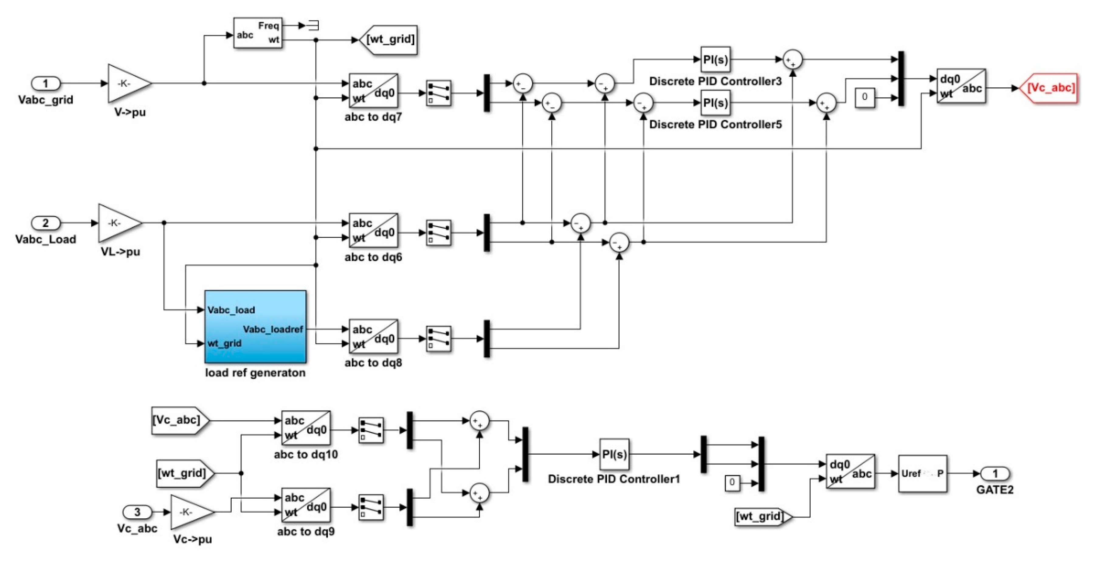
3.1. Shunt Converter Control

The bidirectional charger offers the capability to discharge the battery to support the grid. Four-quadrant operation enhances its ability to provide or absorb active and reactive power, as it can operate at any point on the P-Q plane. This is possible as weight and size are not significant constrains for off-board charging stations [15,18].
For the shunt-connected converter used in this study, the charger current ( i c ( t ) ) and its phase angle (θ) are used as control variables. The active and reactive power can both be controlled by adjusting the magnitude and phase of the output current of the converter.
The control action is generated by transforming the current and voltage time varying quantities to time invariant quantities so that linear control may be performed without introducing any steady state error. This can be done by d-q reference frame transformation using the park transformation technique. The d-q frame voltage and current are used to compute the active and reactive power. It is possible to independently control the flow of active (P) and reactive (Q) power components by decoupling the two components of current (d and q components). Therefore, (id) and (iq) are the variables used to control (P) and (Q). The controller developed in this study can operate in three modes as follows.

3.1.1. Voltage Mode

When there is no power command, the grid converter regulates the DC-link voltage employing the V-I double closed control scheme using a PI controller, as described in the equations below [17].
i d * = k p ( V DC , ref V DC ) + k i ( V DC , ref V DC ) dt
i q * = 0
where ( V DC , ref ) is the desired DC-link voltage, ( V DC ) is the measured DC-link voltage, ( k p ) is the proportional constant and ( k i ) is the integral constant of the PI controller.

3.1.2. Power Mode

If there is an active or reactive power request from the EV user or the electric grid, the controller must track these commands. The active power command can be satisfied by comparing the requested active power from the grid with the desired reference power and setting ( i d * ) , whereas the reactive power command is satisfied by setting ( i q * ) , which is obtained by comparing the requested reactive power form the grid with the desired reference reactive power. In this study, both the active and reactive power can be requested by the EV user or the electric grid. Two PI control loops are utilized to generate both the active ( i d * ) and reactive ( i q * ) current references.
When there is no reactive power request from the grid, i d * and i q * references are given by [6]:
i d * = k pp ( P ref P ) + k ip ( P ref P ) dt
i q * = 0
If there is a reactive power request from the grid, the controller will follow the reactive power commands by setting ( i q * ) , which is obtained from the desired ( Q ref ) , which is compared with the requested (Q) as follows [17]:
i q * =   k pq ( Q ref Q ) + k iq ( Q ref Q ) dt
In both the voltage and power modes, the same inner current loop is used. The obtained current references, i d * and i q * , are then compared to the measured current components of the charger current, ( i c ) which then passes through a PI controller.

3.1.3. Compensation Mode

If there is small voltage sag, it can be effectively compensated. In this compensation technique, the load current, point of common coupling (PCC) voltage and the DC-link voltage are measured as feedback signals [28]. In this study, to be able to respond to an active power command for charging the EV battery, while supplying the required reactive power compensation, the active power is also measured as a feedback signal. Two PI controllers are employed for the outer and the inner control loops, and by appropriate tuning, the pulse width modulation (PWM) control signals for the AC/DC converter will be generated. The outer voltage loop of the reference active current component ( i d * ) is satisfied either by regulating   ( V DC ) or an active power command. The inner loop regulates the measured grid current ( i s ) at the PCC.
When there is no power command, the grid converter regulates the DC link voltage, whereas the reference active current component ( i d * ) is satisfied by adding the active current component of load current to the active current component that is obtained by comparing the measured DC voltage with its reference [28]:
i d * = i dL + k p ( V DC , ref V DC ) + k i ( V DC , ref V DC ) dt
If there is an active command from the EV user, the reference active current component ( i d * ) is satisfied by adding the active current component of the load current ( i dL ) and active current component that is obtained from comparing the measured active power with the desired reference power:
i d * = i dL +   k pp ( P ref P ) + k ip ( P ref P ) dt
On the other hand, the reactive current component ( i q * ) is satisfied by adding the reactive current component of the load current ( i qL ) and reactive current component that results from comparing the measured amplitude ( V mag ) at the PCC voltage with the desired reference voltage ( V mag , ref ) [6]:
i q * = i qL + k p ( V mag , ref V mag ) + k i ( V mag , ref V mag ) dt
For the compensation mode, the inner loop controls the sensed active and reactive grid current components ( i s ) . Two PI controllers are employed for this purpose. The resultant components from the PI controllers, e d   and e q , are first summed with decoupling terms and are then normalized by the DC-link voltage ( V dc ) to get the duty ratios in the d-q frame ( d d , d q ) , as shown in the following matrix [1]:
[ d d d q ] = 1 V dc [ e d + v d + 3 ω L × i q e q + v q 3 ω L × i d ]
where ( v d ,   v q ) and ( i d ,   i q ) are the charger d-q voltages and currents respectively. It was assumed that the total impedance between the grid and the charger is pure inductive and lumped together as (L). However, to get duty ratios in the a-b-c frame of reference ( D a ,   D b ,   and   D c ) , an inverse matrix transformation technique is utilized, as shown below [1]:
[ D a D b D c ] = 2 3 [ sin ( ω t ) cos ( ω t ) sin ( ω t 2 π 3 ) cos ( ω t 2 π 3 ) sin ( ω t + 2 π 3 ) cos ( ω t + 2 π 3 ) ] × [ d d d q ]
Figure 3 shows the system controller diagram of the shunt converter. Simulink was used to realize the mathematical operation described in the equations. The controller has six inputs: charger input voltage and current, DC-link voltage, active power command, reactive power command, mode of operation and the magnitude of the load voltage.

3.2. Series Converter Control

According to the phase angle of the load voltage there are different methods that may be used to realize voltage injection [4,5]. In this study, the in-phase injection method is used to minimize converter rating. The disadvantage of this method is that active power must be injected into the load, which depends on the EV battery size and amount of energy stored [29].
The control action used for the series converter in this study is based on the estimation of the injected voltage and the reference load voltage for power quality improvement. The injection of the voltage can be directly controlled by estimating the reference injected voltage. However, in order to find the reference injected voltage, the reference load voltage, the sensed load voltage and the sensed voltage at PCC are estimated for an indirect voltage control. The converter voltage is sensed to derive the IGBT gate signals. The reference load voltages are extracted using the derived unit vectors [28,30]. The amplitude of the load voltage is calculated as [28,30]
V L = 2 3   ( v La 2 + v Lb 2 + v Lc 2 )
In addition, the unit vectors are calculated as
u a u b u c = 1 V L [ v La v Lb v Lc ]
Hence, the reference load voltages are estimated as
[ v La * v Lb * v Lc * ] = V L * u a u b u c
( V L * ) is the reference value of amplitude of the load terminal voltage. The load voltages are converted into the d-q rotating reference frame using Park’s transformation with unit vectors (sin θ, cos θ), which are derived using a phase locked loop (PLL) as
[ v Ld v Lq v L 0 ] = 2 3 [ cos θ sin θ 1 2 cos ( θ 2 π 3 ) sin ( θ 2 π 3 ) 1 2 cos θ ( θ + 2 π 3 ) sin θ ( θ + 2 π 3 ) 1 2 ] [ v La v Lb v Lc ]
Similarly, the reference load voltages and the supply voltages are also converted into the rotating reference d-q frame. Then, the series converter voltages are obtained in the rotating reference frame as
v Cd = v Sd v Ld
v Cq = v Sq v Lq
where ( v Sd and v Sq ) are the d-q frame supply voltages, ( v Ld and v Lq ) are the d-q frame load voltages, and ( v Cd and v Cq ) are the d-q frame series converter voltages. Now, the error between the reference and actual voltages in the rotating reference frame are regulated using two PI controllers:
v * Cd = v * Ld v Ld
v * Cq = v * Lq v Lq
Reference compensating voltages in the a-b-c frame are obtained from a reverse Park’s transformation taking ( v * Cd ) and ( v * Cq ) from the equations below and ( v * C 0 ) as zero:
[ v * Ca v * Cb v * Cc ] = 2 3 [ cos θ sin θ 1 cos ( θ 2 π 3 ) sin ( θ 2 π 3 ) 1 cos θ ( θ + 2 π 3 ) sin θ ( θ + 2 π 3 ) 1 ] [ v * Cd v * Cq v * C 0 ]
The reference series converter controller voltages and the sensed series converter controller voltages are first compared and then passed through a PI controller in order to generate a modulating signal that is used in a PWM controller unit to generate gate pulses for the series connected converter. Figure 4 shows the control system of the series converter used in the study.

3.3. DC/DC Converter Control

Among various charging strategies, the constant-current constant-voltage (CC-CV) control strategy is commonly used for Li-ion batteries, and it is suitable for fast charging, as it enables complete charging without overcharging. However, in this study the CC-CV based charging control is not the best choice, since the power is not constant as the voltage increases during the constant-current (CC) mode and the current decreases during the constant voltage (CV) mode. Furthermore, there is no control of the DC-link voltage with this mode of operation. Moreover, it does not account for the power loss in the converter as the measured values are taken from the battery side and not from the grid interface [31]. For these reasons, the constant power charging control strategy is adopted in this study. It has simple control and enables charging at constant power levels. The power will be calculated at the point of common coupling (PCC) and then used to dictate the charging current.
At first, the control strategy must decide the mode of operation according to the direction of power flow. In charging mode, the error between the reference and measured battery current is computed and passes through the PI controller to tune the output used to generate pulses to trigger the buck switch, whereas in the discharging mode, it is used to trigger the boost switch.
In this control, the ( P command )   , which is the power commanded for charging or discharging, is divided by the battery voltage ( V bat ) to determine the battery current reference ( I bat , ref ) . Then, the measured battery current ( I bat ) is compared with the reference current ( I bat , ref ) , the error is then sent to the PI current controller and its output produces the duty ratio. The PWM then produces gate pulses to trigger the switches of the DC/DC converter. During the V2G mode of operation, the EV battery is discharged to supply power in the reverse direction, to deliver the desired amount of power from the battery. Figure 5 shows the control system of the DC/DC converter used in this study.

3.4. Local Controller

The local controller is a control algorithm implemented to function as the system’s operator, in order to detect for voltage sag occurrence and to arrange the power transfer control mechanism between EV batteries and the power grid. Figure 6 shows the local controller mask block.
The local controller needs to define the G2V and V2G power requirements and distribute them accordingly. It must also define the process through which it drives the references and then send these reference signals to the grid side converter and EV side controllers. The local controller initiates by monitoring the grid voltage to detect any voltage sag events. Reduced fast Fourier transform (RFFT) has proven to be an advanced method based on fast Fourier transform (FFT) that works well in grid connected applications [32]. The RFFT code is created using Python 2.3, which outputs the needed equations that may be adapted for any simulation tool [33]. A voltage sag of depth 0.5 was created from 0.2–0.4 s of simulation time, as shown in Figure 7a, to examine the working ability of this method when applied to the proposed system. At the beginning and at the end of the voltage sag, there was a significant increase in the harmonic content, especially the low order components, which serves as an indication that a fault has happened in the system. Hence, at this time the total harmonic distortion (THD) exceeded the acceptable limit of 5%, and the control system outputs a “1”, as shown in Figure 7b.
Once a voltage sag event is detected, the local controller determines the depth of voltage sag by calculating the sag factor, which is then used to select the mode of operation and engage the appropriate switches. The sag factor is calculated as follows [34]:
X = V V N
where (X) is the voltage sag factor, (V) is the RMS voltage at PCC when a sag occurs and ( V N ) is the RMS voltage at PCC during normal operation.
The active and reactive power requirements are then determined by calculating how much power is required to charge the EV battery and how much active and reactive power is available to support V2G operation during voltage sag. The available energy in the EV battery can be calculated using its initial SOC, as given below [18]:
E ava = E cap × SOC 0
  ( E cap , E ava ) are the rated capacity and the available energy in the EV battery respectively; ( SOC 0 ) is the initial state of charge. The energy required ( E req ) for a full charge can be calculated as [16]
E req = E cap   E ava
Thus, the required power ( P req * ) to charge the EV according to the required power to fully charge during G2V mode is given as [18]
P req * = E req E cap   P rated
where ( P rated ) is the rated power of the charging station. Now, based on the rated power for the charging station, the rated capacity of EV battery and available energy in the EV battery can be determined. For discharging during V2G mode, the power available in the EV battery is calculated by first considering the time it takes to charge/discharge the battery:
t = E cap P rated
Hence, the available power in the EV battery is
P ava * = E ava t
It should be noted that during the G2V mode of operation, the power reference signal is determined based on the EV user’s desire for fast charging in order to charge and go or full charge in order to charge and park. In the first case, the rated power of the charger is set as a reference power for controllers, and if the power commanded from the EV user is the power required for a full charge, then it can be calculated according to SOC, and the power reference is sent to controllers as ( P command ) .
P command = { P rated                                               Fast   Charging     P req *                                       Required   to   Full   Charge  
Once deep voltage sag is detected, it calculates the amount of power available that can be extracted from the EV battery and the required active power ( P cont ) that needs to be discharged for zero phase angle jump as follows [34]:
P cont = 3   [ 1 V ] × P Load
where ( V ) is the RMS voltage at PCC when the sag occurs in (PU), and ( P Load ) is the load active power. Based on the available active power that can be extracted, the following logic can then be applied to assess if the available power ( P ava ) in the battery matches the required active power to compensate for the voltage sag, and the power reference is sent to controller as ( P command * ) :
P command * = { P cont      P cont < P ava     P ava        P cont > P ava  
The reactive power demand is continuously monitored, and whenever it’s needed, the local controller responds immediately. The reactive power reference ( Q ref ) is requested directly from the grid. The maximum reactive power capability of the off-board charger is calculated using
Q max = S 2 P ref 2
where ( S ) is the apparent power rating of the charger, and ( P ref ) is the requested active power for charging the EV’s battery. The full reactive power support that can be provided by the charger when active power equals to zero is
Q ref = S
These calculations can now be coordinated with the conditional statements given below, where it is forwarded to the shunt converter controller as ( Q command * ) :
Q command * = { 0 No   Q   requests Q ref   Q ref   Q max       S 2 P 2     Q ref > Q max   S P ref = 0  
It should be noted that when a small voltage sag is detected, with a sag factor between 0.85–0.9, the controller will automatically send the required amount of reactive current to compensate, even while charging the EV battery. On the other hand, when a deep voltage sag is detected, the local controller responds by first checking the state of charge (SOC) of the battery, which is defined as the remaining capacity of the battery, and if it is above 20%, active power support can be provided through discharging of the EV battery. The local controller employs an algorithm to drive the off-board charger operation. The algorithm first acquires values from the input signals, and then the calculations are done in real time to determine the appropriate mode of operation at which it satisfies both the EV user and the electric grid. Figure 8 shows the flow chart of the proposed algorithm.

4. Results

In order to verify the performance, validate the operation and prove the proposed charger’s capability to effectively work in the mentioned operation modes, a simulation model is implemented in MATLAB/Simulink. The proposed system in Figure 1 is simulated as shown in the model of Figure 9; the grid is modelled as a 120 kV three-phase programmable voltage source with variable amplitude, so it can be programmed in order to create voltage sags with different depths. The grid model includes an internal step-down transformer to reduce the voltage to the distribution level shown in Figure 9. The load chosen for this study is 20 kVA with a 0.95 lagging power factor. The EV battery was modelled using a SimPowerSystems rechargeable battery block. The system components and parameters that are used in the model are listed in Table 1. It should be noted that the positive sign refers to EV battery charging while the negative sign refers to power being injected into the grid.
First, the charger’s capability to work in each of the four quadrants, in addition to the borders of the P-Q plane, is examined and verified. Eight simulation scenarios were run for eight active and reactive power values, taking into account that these values will be varied while keeping S fixed at 53 kVA. For these simulations, the charger voltage and current were investigated. The simulation results of the charger voltage and current for each P and Q requested value where the current either leads or lags the voltage is shown in Figure 10. The results demonstrate that the charger is perfectly capable of the four-quadrant operation under steady state operation. It should be noted that when the active power command arrives, the power requires time to reach the steady state value Therefore, the current waveform changes with the change in the active power in order to keep the voltage constant.
In order to validate the proposed charger’s capability in effectively responding to the charging and discharging power commands, several simulation scenarios were considered. The DC-link capacitor is capable of reactive power operation for small voltage sag compensation even if the EV is not connected. Figure 11a shows the sagged voltage waveform of a depth of 0.85 pu and the compensated load voltage waveform to nearly 0.93 pu, as shown in Figure 11b.
It was also found that the shunt converter successfully provided the necessary reactive power compensation for small voltage sags of depths in the range of 0.85–0.9 pu while charging the EV battery, as shown in Figure 11c. Where a small voltage sag of a depth of 0.86 pu was created, as shown in Figure 11d, while charging the EV, the charger was able to charge the electric vehicle at the commanded power, while providing reactive power compensation to the voltage at PCC and raise it to 0.92 pu, as in Figure 11e.
The series converter was able to compensate for deep voltage sags with a depth of 0.7 pu. In this case, the series converter was triggered and the charging process was stopped and the battery started to discharge, as shown in Figure 11f, to provide a series voltage to compensate for this sag, as shown in the Figure 11g. However, although the detection technique was perfectly able to detect voltage sag in a very short time, there was a delay in compensating for deep voltage sags of about 0.015 s. This delay was introduced by the time the DC/DC converter control needs to move from charging to discharging, as when this compensation technique was tested alone, before being integrated into the whole system, it showed a perfect voltage compensation with no delay in the compensation process.
In order to validate the charger’s ability to respond to both inductive and capacitive requested reactive power operation, reactive power was requested by the grid while the EV battery was charging. The control system was able to track the commands values, as shown in Figure 12, with relatively low error in following the commanded values.
The grid may request that the system transitions from capacitive to inductive reactive power operation or vice versa. Figure 13 validates that the system can smoothly transition from one reactive power state to the other.
In this control algorithm, the charging process and the user choice for supporting the grid or not, is always a priority. Therefore, a deep voltage sag with a depth of 0.6 was created, but the EV user is not willing to support the grid. Therefore, the control system will continue the charging process of EV battery as shown in Figure 14.

5. Discussion

The goal of this study was to design and develop a “smart” or “intelligent” grid-vehicle interface system. The term intelligent refers to the charger’s ability to control the charging and discharging of the EV battery according to grid conditions, available stored energy and user desire. This is done bidirectionally, allowing power flow from the grid to the EV battery and vice versa. To achieve this goal, this study explored all area of the design and control procedures.
In this study, charging the EV at different power levels was taken in consideration in addition to the flexibility that allows the EV user to choose whether or not to participate in electric grid support, facilitating V2G-based applications in a smart grid environment through mitigating power quality issues. Moreover, the individual control scheme for each converter for charging and discharging EVs and the overall control strategy for the whole system was presented.
Simulations were conducted to validate the three main requirements of the intelligent charger. First, it was shown that the charger is capable of working in all four quadrants of the P-Q plane. Next, the system was validated for its ability to detect voltage sags as part of the control system. Finally, the control system is able to offer completely decoupled active and reactive power command control. It was shown that the system is able to track the references with a relatively low error and respond to sudden changes in the modes of operation according to grid and user conditions without losing system stability. The developed control algorithm can efficiently manage the grid/user input signals to determine the required modes of operation in order to output the required active and reactive power references, to drive the operation of each converter, which allows the charging and discharging of EVs.
From the results obtained, it was shown that the DC-link capacitor is capable of reactive power operation for small voltage sag compensation, even if the EV is not connected. It was also found that the shunt converter was able to successfully provide reactive power compensation for small voltage sags of depths in the range of 0.85–0.9 pu, while the series converter was able to compensate deep voltage sags. However, although the detection technique was perfectly able to detect voltage sag in a very short time, there was a delay in compensating for deep voltage sags by about 0.015 s. This delay was introduced due to the time the DC/DC converter control needs to move from charging to discharging. The system was also shown to be able to smoothly transition operation from inductive to capacitive reactive power operation, based on grid and EV request.

6. Conclusions

In this paper a multifunctional intelligent bidirectional electrical vehicle (EV) charger able to provide voltage sag compensation was described, designed and validated through MATLAB/Simulink simulations. A detailed description of the design of the power and control subsystems, in addition to the simulation parameters, was discussed. The proposed solution was shown to effectively meet three main requirements: charging the EV battery at different power ratings, detecting the voltage sag event and, finally, providing the required active and reactive power compensation for voltage sag compensation.

Author Contributions

Conceptualization, O.S. and Z.D.; methodology, O.S.; software, A.A.N.; validation, O.S., Z.D. and A.A.N.; formal analysis, A.A.N.; investigation, A.A.N.; resources, O.S.; data curation, Z.D.; writing—original draft preparation, A.A.N.; writing—review and editing, O.S.; visualization, Z.D.; supervision, O.S.; project administration, Z.D.; funding acquisition, O.S. All authors have read and agreed to the published version of the manuscript.

Funding

This research received no external funding.

Acknowledgments

This work is supported by the deanship of scientific research at the German Jordanian University.

Conflicts of Interest

The authors declare no conflicts of interest.

References

  1. Kesler, M.; Kisacikoglu, M.C.; Tolbert, L.M. Vehicle-to-grid reactive power operation using plug-in electric vehicle bidirectional off board charger. IEEE Trans. Ind. Electron. 2014, 61, 6778–6784. [Google Scholar] [CrossRef]
  2. Borlease, S. Smart Grids: Infrastructure, Technology and Solutions; CRC Press: Boca Raton, FL, USA, 2013. [Google Scholar]
  3. Feilat, E.A. Voltage dip estimation techniques, an overview. In Proceedings of the 7th Regional Conference of CIGRE National Committees in Arab Countries, Amman, Jordan, 3–5 November 2007; pp. 1–14. [Google Scholar]
  4. Choi, W.L.; Han, D.; Sarlioglu, B. New configuration of multi-functional grid-connected inverter to improve both current-based and voltage-based power quality. In Proceedings of the 2016 IEEE Energy Conversion Congress and Exposition (ECCE), Milwaukee, WI, USA, 18–22 September 2016; pp. 1–8. [Google Scholar]
  5. Choi, W.; Lee, W.; Sarlioglu, B. Performance evaluation of shunt-series switched multi-functional grid-connected inverter for voltage regulation. In Proceedings of the 2017 IEEE Energy Conversion Congress and Exposition (ECCE), Cincinnati, OH, USA, 1–5 October 2017; pp. 2996–3003. [Google Scholar]
  6. Ashourpouri, A.; Dargahi, M.; Nabavi Niaki, S. Residential voltage dip and swell mitigation using plug-in hybrid electric vehicle in smart grid. In Proceedings of the 2013 Australasian Universities Power Engineering Conference (AUPEC), Hobart, Australia, 29 September–3 October 2013; pp. 1–5. [Google Scholar]
  7. Zhang, X.; Zheng, F.; Zhang, J.; Huang, J. Grid voltage sags control strategy for photovoltaic inverter based on adaptive dynamic reactive power compensation. In Proceedings of the International Conference on Renewable Power Generation, Beijing, China, 17–18 October 2015; pp. 1–5. [Google Scholar]
  8. Choi, W.; Lee, W.; Sarlioglu, B. Reactive power control of grid-connected inverter in vehicle-to-grid application for voltage regulation. In Proceedings of the 2016 IEEE Transportation Electrification Conference and Expo (ITEC), Dearborn, MI, USA, 27–29 June 2016; pp. 1–7. [Google Scholar]
  9. Hossain, M.; Ali, M. Fuzzy logic controlled power balancing for low voltage ride-through capability enhancement of large-scale grid-connected pv plants. In Proceedings of the 2017 IEEE Texas Power and Energy Conference (TPEC), College Station, TX, USA, 9–10 February 2017; pp. 1–6. [Google Scholar]
  10. Jayasankar, V.; Kumar, N.; Vinatha, U. Enhancement of load voltage compensation using positive sinusoidal sequence regulator in fuzzy logic controlled three phase series active filter. In Proceedings of the 2017 International Conference on Technological Advancements in Power and Energy (TAP Energy), Kollam, India, 21–23 December 2017; pp. 1–6. Available online: https://www.semanticscholar.org/paper/Enhancement-of-load-voltage-compensation-using-in-Jayasankar-Kumar/55f92cbf5df02896dbd37f15e479267e46641859 (accessed on 22 July 2020).
  11. Kubragyi, S.; Luk, P.; Economou, J. Sugeno—PI fuzzy controller for battery bidirectional charging in the electric vehicle to support voltage stability in V2G distribution grids. In Proceedings of the 7th International Conference on Power Electronics Systems and Applications—Smart Mobility, Power Transfer & Security (PESA), Hong Kong, China, 12–14 December 2017; pp. 1–8. [Google Scholar]
  12. Choi, W.; Wu, Y.; Han, D.; Joseph, G.; Palavicino, P.; Lee, W.; Sarlioglu, B. Reviews on grid-connected inverter, utility-scaled battery energy storage system, and vehicle-to-grid application—Challenges and opportunities. In Proceedings of the 2017 IEEE Transportation Electrification Conference and Expo (ITEC), Chicago, IL, USA, 22–24 June 2017; pp. 203–210. [Google Scholar]
  13. Painuli, S.; Rawat, M.S.; Rayudu, D.R. A comprehensive review on electric vehicles operation, development and grid stability. In Proceedings of the 2018 International Conference on Power Energy, Environment and Intelligent Control (PEEIC), Greater Noida, India, 13–14 April 2018; pp. 807–814. [Google Scholar]
  14. Trovão, J.P.; Pereirinha, P.G.; Trovão, L.; Jorge, H.M. Electric vehicles chargers characterization: Load demand and harmonic distortion. In Proceedings of the 11th International Conference on Electrical Power Quality and Utilisation, Lisbon, Portugal, 17–19 October 2011; pp. 1–7. [Google Scholar]
  15. Kisacikoglu, M.C.; Ozpineci, B.; Tolbert, L.M. Examination of a PHEV bidirectional charger for V2G reactive power compensation. In Proceedings of the IEEE Applied Power Electronics Conference and Exposition (APEC), Palm Springs, CA, USA, 21–25 February 2010; pp. 458–465. [Google Scholar]
  16. Kisacikoglu, M.C.; Ozpineci, B.; Tolbert, L.M. EV/PHEV bidirectional charger assessment for V2G reactive power operation. IEEE Trans. Power Electron. 2013, 28, 5717–5727. [Google Scholar] [CrossRef]
  17. Sun, B.O.; Dragicevic, T.; Savaghebi, M.; Vasquez, J.C.; Guerrero, J.M. Reactive power support of electrical vehicle charging station upgraded with flywheel energy storage system. In Proceedings of the 2015 IEEE Eindhoven PowerTech, Eindhoven, The Netherlands, 29 June–2 July 2015; pp. 1–6. [Google Scholar]
  18. Khan, S.U.; Mehmood, K.K.; Haider, Z.M.; Bukhari, S.B.A.; Lee, S.-J.; Rafique, M.K.; Kim, C.-H. Energy management scheme for an ev smart charger V2G/G2V application with an ev power allocation technique and voltage regulation. Appl. Sci. 2018, 8, 648. [Google Scholar] [CrossRef] [Green Version]
  19. de Melo, H.N.; Trovão, J.P.F.; Pereirinha, P.G.; Jorge, H.M.; Antunes, C.H. A controllable bidirectional battery charger for electric vehicles with vehicle-to-grid capability. IEEE Trans. Veh. Technol. 2018, 67, 114–123. [Google Scholar] [CrossRef]
  20. Brenna, M.; Foiadelli, F.; Zaninelli, D. Voltage sags compensation through a DVR supplied by V2G vehicles charging stations. In Proceedings of the 2013 IEEE PES ISGT Europe, Lyngby, Denmark, 6–9 October 2013; pp. 1–5. [Google Scholar]
  21. Hinz, H. Comparison of Lithium-Ion battery models for simulating storage systems in distributed power generation. Inventions 2019, 4, 41. [Google Scholar] [CrossRef] [Green Version]
  22. Liu, K.; Li, K.; Zhang, C. Constrained generalized predictive control of battery charging process based on a coupled thermoelectric model. J. Power Sources 2017, 347, 145–158. [Google Scholar] [CrossRef] [Green Version]
  23. Shang, Y.; Liu, K.; Cui, N.; Wang, N.; Li, K.; Zhang, C. A compact resonant switched-capacitor heater for lithium-ion battery self-heating at low temperatures. IEEE Trans. Power Electron. 2020, 35, 7134–7144. [Google Scholar] [CrossRef]
  24. Shen, W.; Vo, T.; Kapoor, A. charging algorithms of lithium-ion batteries: An overview. In Proceedings of the 7th IEEE Conference on Industrial Electronics and Applications (ICIEA), Singapore, 18–20 July 2012; pp. 1567–1572. [Google Scholar]
  25. Khan, A.B.; Choi, W. Optimal charge pattern for the high-performance multistage constant current charge method for the li-ion batteries. IEEE Trans. Energy Conv. 2018, 33, 1132–1140. [Google Scholar] [CrossRef]
  26. Liu, K.; Zou, C.; Li, K.; Wik, T. Charging pattern optimization for lithium-ion batteries with an electrothermal-aging model. IEEE Trans. Ind. Inform. 2018, 14, 5463–5474. [Google Scholar] [CrossRef]
  27. Liu, K.; Hu, X.; Yang, Z.; Xie, Y.; Feng, S. Lithium-ion battery charging management considering economic costs of electrical energy loss and battery degradation. Energy Convers. Manag. 2019, 195, 167–179. [Google Scholar] [CrossRef]
  28. Singh, B.; Chandra, K.; Al-Haddad, K. Power Quality Problems and Mitigation Techniques, 1st ed.; John Wiley and Sons Ltd.: Chichester, UK, 2015. [Google Scholar]
  29. Remya, V.K.; Parthiban, P.; Nandakumar, A. Phase advance compensation of voltage sags using full bridge inverter based dvr. In Proceedings of the 2017 International Conference on Technological Advancements in Power and Energy, Kollam, India, 21–23 December 2017; pp. 1–6. Available online: https://www.semanticscholar.org/paper/Phase-advance-compensation-of-voltage-sags-using-Remya-Parthiban/55bc46affb2e76eb9bf05213bae151772799b2f9 (accessed on 22 July 2020).
  30. Mukundan, C.M.N.; Mithun, K.; Jayaprakash, P. Modular five-level inverter with binary sources based dvr for power quality improvement. In Proceedings of the 2017 International Conference on Technological Advancements in Power and Energy, Kollam, India, 21–23 December 2017; pp. 1–6. Available online: https://www.semanticscholar.org/paper/Modular-five-level-inverter-with-binary-sources-DVR-Mukundan-Mithun/fc18f9844a3a0d45777e1a84b9f0168588a84fd9 (accessed on 22 July 2020).
  31. Morris, J. Design and Testing of a Bidirectional Smart Charger Prototype. Master’s Thesis, University of Waterloo, Waterloo, ON, Canada, 2015. [Google Scholar]
  32. Stanisavljević, A.M.; Katić, V.A.; Dumnić, B.P.; Popadić, B.P. Overview of voltage dips detection analysis methods. In Proceedings of the 2017 International Symposium on Power Electronics, NoviSad, Serbia, 19–21 October 2017; pp. 1–6. [Google Scholar]
  33. Stanisavljević, A.M.; Katić, V.A.; Popadić, B.P.; Dumnić, B.P.; Radišić, R.J.; Kovačević, I.M. Reduced fft algorithm for network voltage disturbances detection. In Proceedings of the 2016 International Symposium on Industrial Electronics, Banja Luka, Bosnia Herzegovina, 3–5 November 2016; pp. 1–6. [Google Scholar]
  34. Bollen, M. Understanding Power Quality Problems—Voltage Sags and Interruptions; John Wiley and Sons: Piscataway, NJ, USA, 2000. [Google Scholar]
Figure 1. Proposed system topology.
Energies 13 03784 g001
Figure 2. Proposed system control block diagram.
Energies 13 03784 g002
Figure 3. Shunt converter control system.
Energies 13 03784 g003
Figure 4. Series converter control system.
Energies 13 03784 g004
Figure 5. DC/DC converter control system.
Energies 13 03784 g005
Figure 6. Local controller mask block.
Energies 13 03784 g006
Figure 7. Voltage sag detection simulation results: (a) voltage sag waveform depth of 0.5 pu; (b) detection output signal.
Energies 13 03784 g007
Figure 8. Complete system control algorithm flowchart.
Energies 13 03784 g008
Figure 9. Simulated model schematic.
Energies 13 03784 g009
Figure 10. Per unit charger voltage (blue) and charger current (red) simulation results for: (a) P = 53 kW & Q = 0 kVar; (b) P = 37.4 kW & Q = 37.4 kVar; (c) P = 0 kW & Q = 53 kVar; (d) P = −37.4 kW & Q = 37.4 kVar; (e) P = −53 kW & Q = 0 kVar; (f) P = −37.4 kW & Q = −37.4 kVar; (g) P = 0 kW & Q= −53 kVar; (h) P = 37.4 kW & Q = −37.4 kVar.
Energies 13 03784 g010aEnergies 13 03784 g010b
Figure 11. Voltage sag compensation simulation results. (a) Grid voltage with sag depth of 0.85 pu. (b) Compensated load voltage when no charging command. (c) State of Charge (SOC) of electric vehicle (EV) battery when small voltage sag occurs. (d) Grid voltage of sag of depth of 0.86 pu. (e) Compensated load voltage during small voltage sag event. (f) SOC of EV battery during deep voltage sag compensation. (g) Compensated load voltage during deep voltage sag event.
Energies 13 03784 g011
Figure 12. Charger’s response (red) to reactive power request (blue): (a) inductive reactive power and (b) capacitive reactive power.
Energies 13 03784 g012
Figure 13. Charger’s response: (a) transition from inductive to capacitive operation and (b) transition from capacitive to inductive operation.
Energies 13 03784 g013
Figure 14. SOC of EV battery.
Energies 13 03784 g014
Table 1. Simulation system parameters.
ComponentParameterValue
Distribution SystemPhase voltage220 V
frequency, f50 Hz
AC/DC Shunt ConverterRated apparent power, S 62 kVA
Switching Frequency, f s , s 5 kHz
LCL Input FilterConverter side inductance, L conv 2 mH
Grid side inductance,   L grid 3 mH
Filter capacitor, C f 100 μF
Damping resistance, R d 2.5 ohm
AC/DC Series ConverterRated apparent power, P16 kVA
Switching Frequency, f s 10 kHz
LC Output FilterInductance, L r 6 mH
Capacitor, C r 300 μF
Damping resistance, R r 6 ohm
DC LinkDC link capacitance, C DC 1.3 mF
DC link voltage, V DC 700 V
DC/DC ConverterRated power, P48 kW
Switching Frequency, f5 kHz
DC/DC Output FilterBattery side capacitance, C bat 150 μF
Battery side inductor, L bat 2 mH
LoadPhase voltage,220 V
Grid frequency, f50 Hz

