1. Introduction
With the increase of wearable devices, we can obtain our sports condition, physical condition, or change our perception in real time, making our lives smarter. For example, smart glasses can be used to guide various on-site operations remotely, smart watches can monitor sleep quality and smart shoes can track the wearer’s movement trajectory. These electronic devices are powered by battery, which also has limited limited endurance, especially in outdoor environment. There are three methods that can improve the endurance of wearable devices: new battery technology to make the battery smaller and higher battery capacity; reduce power consumption of wearable devices; and, harvesting energy from human motion to power the wearable devices.
Generally speaking, EH technology has a wide range of uses and can overcome the shortcomings of the current limited battery capacity. EH device could recharge batteries to extend the endurance in real time [
1,
2,
3,
4,
5,
6]. For example, the EH device can power the wireless sensors of the exoskeleton system, which can extend the working hour of the system.
A complete EH system is composed of energy source, energy transducers, transformer, rectifying circuit, electronic filters, voltage stabilizing circuit, storage, and load. A block diagram of system is shown in
Figure 1. Energy transducers convert thermal, vibration, light, and radiation energy from environment into electrical energy. Meanwhile, it also adjusts the voltage level to the rated voltage of the load through transformer. The task of the rectifying circuit is to rectify the AC voltage to a pulsating DC voltage. The electronic filters adjust the pulsating DC circuit into a smooth DC circuit, and the voltage stabilizing circuit outputs a stable voltage. The output electricity is stored in the storage or directly powers to the load. According to the source of energy, researchers have developed different EH device.
Table 1 shows the comparison of harvested power from different energy sources [
3].
There have been many thermal electric generators developed by researchers, which utilize temperature difference between the human body and the environment to generate electricity through thermoelectric materials. When the ambient temperature is 0 °C, according to the Carnot‘s equation, the maximum efficiency of thermoelectric generator is calculated to be 12% [
7]. Therefore, it is feasible to use human body thermal energy to generate electricity. The thermoelectric converters of human temperature developed by Leonov, et al., can generate 250
W of electricity to power wireless sensors [
8]. The thermal electric generator invented by Tom Torfs, et al. can generate 23
W of electricity in a 23
C environment to power the wireless two-channel EEG system [
9].
The harvested power from vibration is the more than the others, so EH devices that convert vibration energy into electrical energy is studied the most, as shown in the
Table 1. Various materials and transduction mechanisms have been developed to convert vibratory energy to electrical energy, such as piezoelectric, electromagnetic, and triboelectric generators [
10,
11]. Generally speaking, the vibration energy source includes energy of the sole of the foot, inertial energy and movement of joints, etc. A cantilever structured piezoelectric energy harvester is designed and generates average output powers about 50
W from the hand-arm motion [
12]. Rome L C and his colleagues develop a suspended backpack to generate electricity, which converts the mechanical energy of vertical movement into electrical energy (up to 7.4 W) [
13]. Hayashida and his colleagues design an electromagnetic rotating device installed at the heel of the shoe. The maximum power generated by the shoe during a heel strike is 1.61 W, and the average power of the entire gait was 58.1 mW [
14]. Donelan and his colleagues design a biomechanical knee energy harvester installed at the knee joint and selectively participated in power generation at the end of the swing phase, to generate an average of 5 W of electricity when subjects walk [
15]. The triboelectric generator that is able to generate an output voltage of up to 3.3 V is designed by Zhonglin Wang and his colleagues [
16].
Photovoltaic based on the photovoltaic effect to convert luminous energy into electrical energy, and flexible solar panels can be conveniently applied to wearable devices for energy harvesting. Magno and his colleagues combine solar cells and thermoelectric generators to design a new EH device that can generate 550 mW of energy under indoor light intensity and 98
W and 250
W with 3
C and 5
C temperature gradient, the energy is able to power multiple sensors continuously [
17].
Radio Frequency (RF) EH devices are able to harvest the RF energy transmitted by mobile communication device, WiFi and Base Station to power low-power wearable devices. The indoor 2.45 GHz WiFi energy harvester designed by Ermeey et al. outputs 1.62 mW of electrical energy for driving external low-power devices [
18]. Presently, the RF energy harvester is facing the urgent problems of antenna, sensitivity, and conversion efficiency.
Nanogenerator (NG), which is a new type of generator different from traditional EH, is designed based on nanomaterials. NG is divided into piezoelectric NG, triboelectric NG, and thermoelectric NG according to the energy source. Piezoelectric NG converts the mechanical energy of bending and compression into electrical energy based on the piezoelectric properties and semiconductor properties of special nanomaterials [
19]. Triboelectric NG designed by Zhonglin Wang converts tiny mechanical energy into electrical energy based on the coupling of triboelectric effect and electrostatic induction effect [
19,
20]. Thermoelectric NG converts external thermal energy into electrical energy with nano-structured pyroelectric materials [
21].
A linear vibration generator is used in this paper. When the human body is walking and running, the linear vibration generator is shaken when lower limbs swing. The device has the characteristics of small size, light weight, and wide range of use. This paper is composed of the following four parts: first, we review the significance and research progress of exploring EH device; second, we elaborate the design guidelines of EH device; then, we introduce the working principle of the power generation system we adopt; and finally, we carry out more groups of experiment testing the efficiency of the device.
2. Design Guidelines of Energy Harvesting Device
It is necessary to consider the following issues when designing the EH device: the conversion efficiency of the system, the applicability of the system, the effect of the additional weight of the device on the wearer’s metabolic energy consumption, and the effect of the EH device on the natural movement of the human.
It is necessary to consider the efficiency of EH device. Theoretical basic research on energy recovery from human movement shows that: the average energy consumption of one person is about
J, which is equivalent to 20 kg of battery energy. A large amount of human energy is released from the body in the form of heat and motion. Therefore, it is possible to harvest this energy to power wearable devices [
7]. The energy that is released by the human body is limited, the higher the energy conversion efficiency of EH device, the more energy can be harvested, which can power more equipments at the same time. Raziel Riemer points out that the efficiency of human energy harvesting devices is more important than the total amount energy harvested [
7]. There are two dimensionless quantities (COH and TCOH) evaluating a EH device efficiency. The cost of harvesting (COH) is evaluation of the additional metabolic power required to generate 1W of electrical power [
15]
where
refers to the difference between walking while harvesting energy and walking while carrying the device, but without harvesting energy. In order to consider the effect of the EH devices’ weight on metabolic power, the total cost of harvesting (TCOH) is proposed to evaluate the additional metabolic power required to generate 1 W of electrical power in comparison with normal walking [
22]
Therefore, to improve the efficiency of the energy harvesting device, we can either increase the efficiency of the system power generation (improve the conversion efficiency of the system circuit, the conversion efficiency of mechanical motion, etc.), or reduce the increased metabolic consumption (reducing the weight of the equipment and more rationally arranging the installation location of the EH device). In this paper, we propose a method to calculate the TCOH by calculating the net work that was done by the muscle in a gait cycle.
where
refers to the additional work done by the muscle at joints.
The application scope of EH device also needs to be considered. The larger the application scope, the more energy can be harvested in more scenarios. The suspended-load backpack can generate up to 7.4 W of electricity [
13]. However, the suspended-load backpack is limited by the load. It stops generating electricity if the load is insufficient. In daily life, one cannot always carry so much weight, so its scenarios of application is limited. Therefore, the EH device should not be restricted by the wearer’s movement speed, terrain, or other additional conditions.
The EH device should be as light as possible. If the weight of the device is too large, then it will increase the wearer’s metabolic energy consumption, and the efficiency of the electricity generation. The rotary electromagnetic generators generally work at high speeds (1000–10000 rpm), and the speed of the human body’s joints is generally 20 rpm. In order to obtain high speeds, a reducer with a high transmission ratio is required. The higher ratio, the higher the energy loss is caused by friction between teeth. Meanwhile, the heavier reducer will increase the wearer’s metabolic. Therefore, the weight of the EH device must be reduced through the innovation of the mechanism. Research shows that the energy cost is the lowest when locating the center of mass of device as close as possible to the body center; An additional 1 kg load on the feet will increase energy consumption by 7%~10%, and an additional 1 kg load on the thighs will increase energy consumption by 4% [
23]. Therefore, when the weight of the device cannot be reduced, the energy consumption that is caused by the device can be reduced by arranging most of the weight of the device as close as possible to the center of mass of the human body.
3. Design of the Energy Harvester
Vibration generator is the main component of the EH device designed by us. The vibration generator is designed based on the principle of electromagnetic induction. As long as the magnetic flux passing through the closed circuit changes, an inductive current will be generated in the closed circuit. According to Faraday law of electromagnetic induction, the induced electromotive force can be calculated:
where:
E reprents induced electromotive force (
V),
n reprents number of turns of the induction coil,
represents the rate of change of magnetic flux. When the number of turns of the induction coil (n = 6500, the diameter of coil is 0.31 mm) is constant, the higher the rate of change of magnetic flux, the greater the inductive electromotive force. The vibration generator is customized at ETY Technology Co., Ltd.,Shenzhen, China The EH device is as shown in the
Figure 2.
The vibration generator is composed of a metal shell and a built-in vibration power generation device, which absorbs the slight vibration energy of the surrounding at any time and converts vibration energy into electrical energy. The internal structure of the vibration generator adopts a spring-free cavity structure and magnetic levitation technology. The output end of the vibration generator is connected to conversion circuit and a voltage stabilizing circuit. conversion circuit, and a voltage stabilizing circuit. The output electricity is stored in a 100 mAH fast-charge battery. The higher vibration frequency is, the more energy can be harvested. The product parameters of the vibration generator are shown in
Table 2.
To precisely measure the average output voltage of vibration generator, an experiment table is built, which is shown in
Figure 3. The motor and guide rail are installed on the experiment table, and the vibration generator and the Inertial Measurement Unit (IMU) are installed on the slide block. The motor drives the slider crank mechanism to slide at different speeds, and the IMU is used to monitor the speed of the slider in real time. The slide stroke is 60 mm and the frequency range is 1 to 5 Hz. Before each experiment starts, it will ensure that there is no remaining electrical power in the vibration generator. The ADC of STM32F407 is used to record the voltage of resistor (
R = 1 kΩ).
Table 3 illustrates the average output voltage of vibration generator at different vibration frequency.
As shown in the
Figure 4, the process of generating electricity is illustrated. Generally speaking, a complete gait cycle can be divided into 7 phases: heel strike, loading response, mid-stance, terminal stance, pre-swing, toe-off, mid-swing, and terminal swing. At the phase of heel strike, the heel is lower than the toe, the magnet slides to the lowest point; at the phase of loading response and mid-stance, the magnet is still at the end of the generator because the vibration generator is horizontal; at the phase of terminal stance, pre-swing and toe-off, since heel is higher than the toe, the magnet slides to the front of the generator. During the sliding process, the magnet passes through the closed coil, causing a change in the magnetic flux in the coil, which generates an induced electromotive force in the coil; at the phase of mid-swing, the heel is lower than the toe, the magnet slides from the toe to the heel, and the magnet passes through the closed coil again, causing the coil to changes in magnetic flux, which generates another induced electromotive force in the coil. In one gait cycle, the magnet in the vibrating generator on one foot passes through the closed coil twice.
4. Experiment and Result
In
Section 2, design guidelines of EH device are introduced. In this section, we will conduct experiments are conducted to evaluate the performance of the EH device [
24]. Experiments are divided into experiment A, B, and C. Experiment A is used to monitor the metabolic power and electricity power. According to experiment data, the COH and TCOH of EH device are calculated. Experiment B is conducted to test the adaptability of the EH device under the different conditions of terrains and walking speeds. Experiment C is conducted to investigate the influence of the EH device on human motion, including the torque of the ankle, knee, and hip joints.
4.1. Experiment A
One important parameter of EH device is efficiency. Under the same conditions of human walking, the higher the efficiency, the more electricity power can be harvested. Therefore, the purpose of this experiment is to quantify the efficiency of the EH device during walking. Generally, COH and TCOH are used to quantify the efficiency of the EH device. The smaller the value, the higher the efficiency.
Experiment setup: three healthy male adults (
years old,
kg,
cm), with no leg diseases, participate in this experiment. As shown in
Figure 5, the experiment is conducted on a treadmill at a slope of 0
and the temperature of 26
C. We measure the metabolic rate and electrical power of EH device at the speed of 4 km/h, 5 km/h, 6 km/h, 7 km/h, and 8 km/h, respectively. To measure the metabolic rate, COSMED−K5 (Wearable Metabolic Technology, Italy) is used to record the exhaled pulmonary gas concentrations and volumes, which are mainly composed of carbon dioxide and the oxygen. According to the modified Brockway equation [
25], as shown in Equation (
5), the metabolic energy expenditure is calculated [
26].
where the coefficients
is 16.89 and
is 4.84. To measure the electrical power, ADC of STM32F407 is used in order to monitor the voltage of resistor (
R = 1 kΩ). The electrical power is calculated according to Equation (
6).
Experiment procedure: in order to minimize the interference to the experiment, three groups of experiments are conducted in three days. On day 1, the control group is conducted to measure the metabolic rate without carrying EH device, on day 2 one of experiment groups is conducted to measure the metabolic rate while carrying the same weight load as the EH device, the other experiment groups is conducted to measure the metabolic rate and the electrical power while carrying the EH device. A subject needs to conduct a total of five experimental tests in one day. Therefore, to reduce the experiment error caused by the subject’s fatigue, 10-min break is set between each experiment.
Experiment results: to prevent end-effects, the experiment data of subject at steady state is analyzed. The metabolic power of each walking trial is calculated according to Equation (
5). The net metabolic change is calculated by subtracting the resting metabolic cost from the total metabolic cost. According to the voltage value of the output resistor, the output electrical power can be calculated based on Equation (
6). The COH and TCOH of the EH device is calculated according to Equation (
1) and Equation (
2). The experimental results of three subjects are shown in the
Table 4 and
Figure 6. As presented in
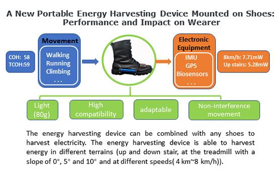
Table 4, the lowest COH and TCOH are 58 and 59, respectively. The values of COH and TCOH are relatively close, which means that the energy cost of carrying the EH device is negligible. When compared to the lower limb-driven energy harvester [
22], the TCOH of the EH device is higher.
4.2. Experiment B
If an EH device can be adapted to various movement situations, then the device will have promising application prospect. An adaptable energy harvesting device should not be affected by the way of movement, the speed of walking or running or the terrain of the movement. Therefore, the purpose of this experiment is to test whether the EH device is limited by terrains (uphill and stairs) and speeds.
Experiment setup: the experiment subjects, experiment apparatus, and experiment environment are the same as experiment A. We separately measure the voltage of the output resistor of the EH device when the subjects are walking on the treadmill at different slope and speeds.
Experimental procedure: in order to reduce the interference to the experiment, experiments are also conducted in three days. On day 1, we measure the voltages of the output resistor of the EH device when the subjects are walking at speed of 4 km/h, 5 km/h, 6 km/h, 7 km/h, and 8 km/h on the treadmill at the slope of 0 and speeds. Each walking trial lasts 10 min and there is a 20 min break for the subject to restore from fatigue. On day 2 and 3, the same experiments are conducted at the slope of 5 and 10. In addition, we also measure the voltages of the output resistor of the EH device when subjects go up and down stairs. In consideration of safety during up and down stairs, auxiliary protection personnel help to ensure the safety of subject in emergency situations.
Experimental results: we calculate the electrical power according to the Equation (
6).
Table 5 and
Table 6 illustrate the average electrical power (AEP) and power density (PD) of the EH device. As shown in tables, it is clear that the EH device is able to harvest energy in different terrains and at different speeds. However, the amount of electrical power is influenced by terrains and speeds; as the speed of walking increases, the amount of electrical power also increases.
4.3. Experiment C
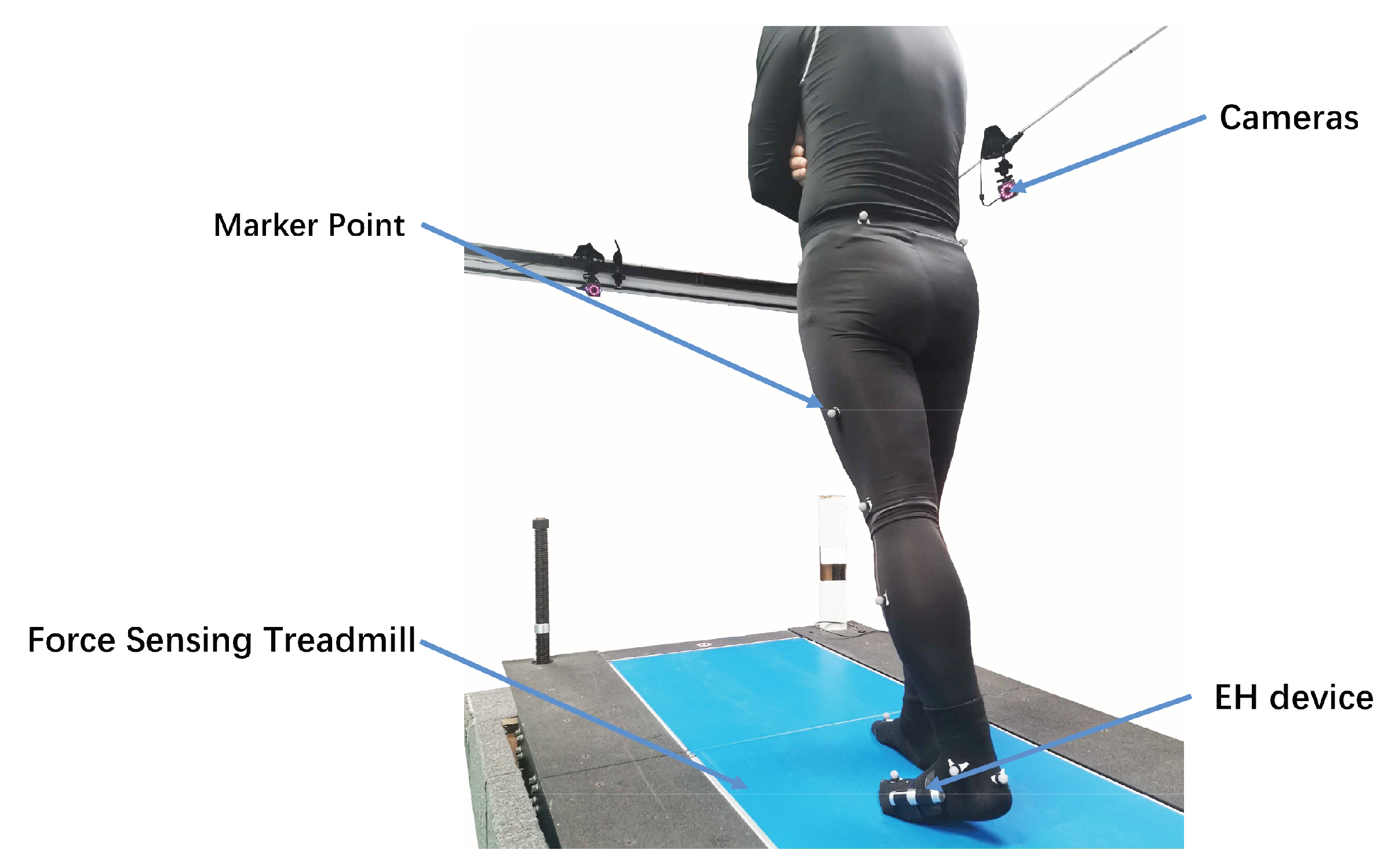
The EH device, which converts the kinematic energy of human motion into electrical energy, should not affect or as little as possible influence the movement of subjects. In this experiment, the Vicon motion capture system and force treadmill are used to measure the joint torque of ankle, knee and hip with and without EH device to quantitatively indicate whether the EH device interferes with the motion of the human.
Experiment setup: the subjects are the same participants from experiment A. The EH device designed by us is fixed on the shoes and it mainly harvests the energy of movement generated by the rotation of the ankle during walking. However, since ankle, knee and hip joints are all involved during walking, it is necessary to measure the biological moments of all three joints. The Vicon motion capture system (Oxford Metrics Limited, England) and force treadmill (AMTI, USA) are used for the measurement of biological torque. The experiment adopts the scheme of 16 marked points for testing. The subject walks at a speed of 4 km/h at inclination of 0°, 5°, and 10°, respectively, and biological moments of the three joints with and without EH device are recorded separately.
Experimental procedure: the experiment is shown in
Figure 7. First, we measure the dimensions of the subject’s body, and reconstruct the model of the human body in software of Vicon Nexus according to these parameters. Second, we perform calibration and attach marked points according to the Vicon motion capture system operation manual. Third, we measure the biotorque of each joint of the subject with and without EH device separately through the Vicon system. Each walking trial lasts 10 min, half an hour is kept between each trial. The experimental procedure of each trial is identical at different inclination of force treadmill.
Experiment results: by analyzing the experimental data through the software of Vicon Nexus 2.8, we can obtain the biological moment of the joint during walking. In order to avoid the influence of the data at the beginning and end of the experiment, we selected the experimental data in the stable state for analysis.
Figure 8 shows the biological moment curves of each joint with and without the EH device at different inclinations. When comparing the curve, the EH device has almost no effect on the biological moment of the wearer’s joint, which means that the EH device does not interfere with the movement.
The movement of wear is not interfered by EH device, so the EH device is able to work with wearable exosuit together. In the system of wearable exsuit [
27], foot pressure sensors or wireless IMU are powered by additional battery. These sensors are far away from the exosuit, it will increase the complexity of system if they are powered with cable. There is a contradiction that a larger battery will increase the weight of the system, and a smaller battery cannot power enough electrical energy. The problem is easily solved to power sensors with EH device, which is close to sensors. In the future work, we will continue to explore how to power different sensors with the EH device.
According to the positive and negative work of ankle, knee, and hip joints performed by muscle during a gait cycle, the power of the joints is divided into several phase [
28]. Accordingly, the total power of a joint in a gait cycle can be calculated according to the Equation (
7).
The EH device that is designed by us is driven by the movement of lower-limb, so there is a new method to calculate the TCOH. TCOH can be calculated through the additional work in a gait cycle, which is required to generate 1 W electrical power, done by muscle at joints in a gait cycle. The TCOH of the EH device is calculated according to Equation (
8); the result is shown in
Table 7 and
Figure 9.
5. Conclusions
With the development of microelectronic technology, increasing wearable devices are available for us in daily lives. These wearable devices are usually powered by batteries, so the endurance of wearable devices are limited by battery capacity. Biomechanical EH is a promising approach to extend the endurance or replace batteries to power the device.
First of all, different types of EH devices are reviewed and key technologies are analyzed. Secondly, when comparing the advantages and disadvantages of different EH devices, design guidelines of the EH device are proposed. Next, according to design guidelines, an EH device with a weight of only 110g is designed, which is lighter than the suspended-load backpack (38 kg) [
13] and the knee harvester (1.6 kg) [
22]. The EH device is able to convert the vibrations energy generated by the motion of lower limbs into electrical energy. Finally, three sets of experiment are conducted to evaluate the performance of the EH device to verify whether our energy harvesting device meets design guidelines. Experiment A is used to monitor the metabolic energy and electricity energy. According to experiment data, the COH and TCOH of EH device are calculated. The lowest COH and TCOH are 58 and 59, respectively. The TCOH of our EH device is higher suspended-load backpack (30.7) and the knee harvester (13.6). Experiment B is used to test the adaptability of the EH device under the different conditions of terrains and walking speeds. The EH device is able to harvest energy under different terrains(up and down stair, at the treadmill with a slope of 0
, 5
and 10
) and at different speeds (4 km/h~8 km/h). The converted electrical power is up to 7.71 mW during walking at the speed of 8 km/h and it is up to 5.28 mW during going up the stairs. Experiment C is to conducted to investigate the influence of the EH device on human motion by measuring the torque of the ankle, knee and hip joints. When comparing the curves of torque, the EH device does not interfere with human motion. At the same time, another method to calculate the TCOH by calculating the net work done by the muscle in a gait cycle is proposed. When comparing the TCOH calculated by the metabolic power with the TCOH calculated by the additional work done by the muscle, as shown in
Table 4 and
Table 7, the results are basically the same. Meanwhile the variation of the latter calculation result is smaller, so it is more precise to calculate the TCOH by calculating the net work done by the muscle.
Although the EH device that is designed by us is light in weight, small in size and strong in applicability, its electrical power generation is insufficient and the efficiency is low. In the future work, the following aspects will be researched: first, optimizing the parameters of the EH device (dimensional parameters and inductance parameters, etc.) without increasing the weight of the system; second, installing the EH device in multiple single-degree-of-freedom joint to increase the electrical power of the system; third, combining various forms of EH devices together to convert multiple kinds of energy into electrical energy.

 ,
, 


