Article

A GIS-Based Planning Approach for Urban Power and Natural Gas Distribution Grids with Different Heat Pump Scenarios

1
Department of Energy Management and Power System Operation, University of Kassel, Wilhelmshöher Allee 73, 34121 Kassel, Germany
2
Fraunhofer Institute for Energy Economics and Energy System Technology IEE, Department of Grid Planning and Operation, Königstor 59, 34119 Kassel, Germany
3
Department of Energy Systems, Technische Universität Berlin, Straße des 17. Juni 135, 10623 Berlin, Germany
*
Author to whom correspondence should be addressed.
Energies 2020, 13(16), 4052; https://doi.org/10.3390/en13164052
Submission received: 30 June 2020 / Revised: 27 July 2020 / Accepted: 31 July 2020 / Published: 5 August 2020

Abstract

:
Next to building insulation, heat pumps driven by electrical compressors (eHPs) or by gas engines (geHPs) can be used to reduce primary energy demand for heating. They come with different investment requirements, operating costs and emissions caused. In addition, they affect both the power and gas grids, which necessitates the assessment of both infrastructures regarding grid expansion planning. To calculate costs and CO 2 emissions, 2000 electrical load profiles and 180 different heat demand profiles for single-family homes were simulated and heat pump models were applied. In a case study for a neighborhood energy model, the load profiles were assigned to buildings in an example town using public data on locations, building age and energetic refurbishment variants. In addition, the town’s gas distribution network and low voltage grid were modeled. Power and gas flows were simulated and costs for required grid extensions were calculated for 11% and 16% heat pump penetration. It was found that eHPs have the highest energy costs but will also have the lowest CO 2 emissions by 2030 and 2050. For the investigated case, power grid investments of 11,800 euros/year are relatively low compared to gas grid connection costs of 70,400 euros/year. If eHPs and geHPs are combined, a slight reduction of overall costs is possible, but emissions would rise strongly compared to the all-electric case.

Graphical Abstract

1. Introduction

One important aspect of mitigating climate change is the increase in energy efficiency, particularly in the building sector. The European Union’s amended Directive on Energy Efficiency (2018/2002) sets an energy efficiency target for 2030 of at least 32.5% improvement compared to the 2007 business-as-usual scenario [1,2]. The German government has set a goal of an 80% reduction in primary energy consumption by 2050 compared to 2008 for the building sector [3]. The primary energy consumption of the German building sector decreased by 18.8% from 2008 to 2017 while the overall German primary energy consumption sunk by 5.5%. Space heating and domestic hot water provision in private households accounted for 21.9% of the total final energy consumption in Germany in 2017 [4].
The research field of future energy-efficient heat supply is manifold and consists of various sub-research areas that overlap with other energy research questions. There are three main areas of particular relevance for the present paper that are elaborated on later in this section. Firstly, heat pumps are an important technology with which primary energy consumption can be reduced [5]. They can be evaluated in the light of energy management [6] and regarding their impact on grid infrastructure [7]. Secondly, this impact of heat pumps and other grid-connected heat generators can, in general, lead to violations of operating limits in the respective infrastructure. Thus, grid expansion and reinforcement planning is another relevant research area [8]. While past infrastructure was often planned separately for different energy carriers, e.g., electricity and natural gas, integrated planning of energy infrastructure has become increasingly important in recent publications [9]. Finally, an energy system can be modeled with different spatial resolutions and levels of abstractions [10,11]. On a regional level, geographical information (GIS) on buildings, streets, and existing infrastructure can be included to find site-specific solutions and account for local characteristics.
One of the main instruments with which to reduce CO 2 emissions is better insulation of buildings, thereby leading to lower thermal demand for each building that can be coupled with an efficient thermal energy system such as a heat pump (HP) [5]. Innovative concepts exist to build low energy, zero energy, or even plus energy buildings [12]. For existing buildings, however, energetic refurbishment measures have to be applied to achieve lower heat demand and low flow temperatures, which are suitable for efficient heat pump operation [13]. For some historic buildings, particular regulations on conservation principles limit the options for energetic refurbishments, such as insulation measures [14]. For buildings with higher energy demands, efficient gas-based heating systems with innovative energy management are discussed to help to reduce CO 2 emissions at reasonable costs [15]. For instance, in [16], a combined control for hybrid systems consisting of photovoltaic solar panels (PV) and combined heat and power (CHP) was introduced based on a model predictive control for the electrical and thermal components and a short term, rule-based control for each component. The new control can manage the PV-CHP system with higher efficiency, lower CO 2 emissions, and lower operational costs. The model predictive control was successfully tested in the laboratory [17]. In [18], the authors also showed the flexibility potential of thermal-electrical systems using a model predictive control, which could be used for market or grid-friendly behavior. Nonetheless, even with highly innovative optimized control algorithms, natural gas-fired CHP plants have unavoidable CO 2 emissions. To improve the primary energy factor, ambient heat can be used by heat pumps. Usually, the heat pumps’ refrigerant circuit is driven by electric motors, and auxiliary heating coils might be used. Besides that, heat pump systems are also available with gas-powered engines and additional waste heat recovery. The emission and combustion characteristics of gas engine heat pumps (geHPs) are shown in [19].
Various studies on geHPs for industrial and residential use were reviewed in [20], which concluded that efficiency gains can be reached by using geHPs not only for space heating but also for hot water generation. In-depth energy efficiency analysis of a geHP was conducted in [21,22]; a primary energy ratio up to 1.83 was reported.
In the present study, the idea is to use different heat pump systems as a flexibility option in grid planning, not in energy management. The heat pump hot water storage systems are assumed to have rule-based controls based on leveling the storage temperature to supply the necessary space heating and domestic hot water during a year.
The impact of heat pumps on an electrical distribution grid has been studied in great detail in [23] and corrected in [24] as a function of building type and district properties. It was found that cable overloading can be expected for large rural feeders at heat pump penetrations as low as 30%, depending on the cable, while voltage problems start usually at slightly higher percentages. Additionally, building characteristics show high correlations with the examined grid performance indicators, revealing a promising potential for statistical modeling of the studied indicators. Electrical heat pumps and grid integration were also discussed in the context of flexibility options and demand-side management, e.g., in [25]. The authors show that ground source heat pumps are a very high-efficiency technology for space conditioning in buildings, and present a high potential for electric load management as a flexible load when combined with the thermal storage capacity of the building. In addition, the authors in [26] demonstrate that the combined use of a grid-connected PV system for heat pump water heaters has a larger economic benefit than solar thermal heaters when combined with optimal scheduling and therefore helps with grid integration of PV systems. An energy index was introduced in [27] to assess plants, such as a PV system and heat pump, capable of producing electricity from a renewable source. The index evaluates the bidirectional energy flows on the external power grid, in comparison to the electricity demand of a building. None of these studies considered the costs of a gas distribution grid and the effects of the gas heating systems when building owners changed their heating systems to electrical heat pumps. Such effects can include costs for dismantling existing gas network elements.
Even if electrical heat pump systems based on renewable electricity will be a zero-emission solution in the future, a high number of newly installed electrical heat pumps will lead to problems with the electrical power grid, such as undervoltage and line overloading [28]. As a result, power grid reinforcement measures are required to stabilize the grid. In addition, the start-up characteristics of heat pumps can affect the power grid on short time scales [29]. This can also result in need for expensive grid expansion measures [30]. Frameworks for distribution grid planning are introduced in [31,32]. The latter can be also used for large-scale networks, as shown in [33]. In the past, several aspects of distribution grid planning have been studied. A comparison of meta-heuristics for meshed power grids is elaborated in [34]. Optimizations of low and medium voltage grids have been done [35,36]. A novel approach wherein grid expansion is modeled together with asset management is shown in [37]. A geographic information system (GIS)-based approach was developed by the authors of [38]. In the present study, we also used a GIS-based approach, which includes not only the electrical but also the thermal characteristic of energy demand and its influence on an existing gas distribution grid.
A comparison of optimization methods of gas distribution grids is presented in [39]. The uncertain necessity of dismantling parts of the distribution grid in different ways due to a possibly declining natural gas demand has been recently addressed in [40]. The effects of increasing grid charges for natural gas that incentivize energetic refurbishment have been further investigated in [41].
More research has been done on coupled gas and power grids. A new model for optimal joint scheduling of power-to-gas and gas-fired generation units in a power-gas embedded grid was studied in [42]. This work dealt with operational aspects of a combined infrastructure, not with strategic planning. The authors in [43] analyzed combined planning for enhancing the power grid resilience. A co-simulation approach of gas and power grids was used in [44]. The possibility of using the co-simulation for grid planning was mentioned but not run in detail. A simulation tool for combined power and gas infrastructure (SAInt) was developed in [45] and applied on a 158-bus power grid and a 352-node gas network. However, the case study focused on security-related events and planning was a minor aspect.
A survey on models of integrated power and natural gas grid coordination is presented in [46]. A model for integrated generation, transmission, and gas expansion planning is shown in [47]. In [48], a co-optimization using mixed-integer non-linear programming for modeling a 6-bus power system with a 6-node gas network was shown to be an effective tool for a small number of nodes. Additionally, a mixed-integer linear programming model for optimized integrated planning of power and gas networks was developed in [49] and applied in a case study with an 18 node-power distribution grid that was interconnected with an 18 node-gas network. In the present study, however, no co-optimization approach was used, due to the larger size of the low voltage grid with around 3000 nodes. The focus here is on a techno-economic analysis using a high number of electrical and thermal household loads in a German town for three different cases. A heuristic optimization was used for cost minimal expansion planning of the power grid.
A review of GIS-based modeling of urban energy systems and the FlexiGIS platform is described in [50]. FlexiGIS is an open-source GIS-based platform for modeling urban energy systems. The framework relies mainly on spatial features of urban objects extracted from open databases such as OpenStreetMap. GIS-based studies in [51,52] use the platform to allocate distributed battery storage optimally in urban areas. The simulation and planning of the coupled grid infrastructure is not part of the FlexiGIS model and not mentioned in the literature review. The platform was developed for the optimization of generation and demand of flexibilities in urban regions. In the present paper, we go a step further and add detailed modeling of the gas and power grid infrastructure to the neighborhood energy model of an example town.
In the following, we model both topics in great detail so that it is possible to derive the total costs for a future energy infrastructure that is able to supply electricity and heat in a German town for the years 2030 and 2050. On the one hand, the building owners’ perspective regarding deciding on insulation and the type of heating system is modeled. On the other hand, the grid operator’s perspective toward investing in the power and gas distribution grid to assure a reliable and efficient network infrastructure is modeled as well. The innovation in this paper is to analyze the costs and emissions of heat generation under consideration of different building ages and energetic refurbishment variants in combination with the related costs for grid reinforcement in both the natural gas and the low voltage network of a German town. Using this approach, in contrast to other studies, a more comprehensive assessment of different heating technologies can be conducted, including the cost for heat pump systems and infrastructure costs together. The study shows where a significant number of costs are located and which type of heat pump could be used to minimize the costs but also to reduce CO 2 emissions.
In the context of grid expansion planning, this study presents the following main innovations:
  • The mutual investigation of power and natural gas distribution infrastructure for a whole town using a pipe and power-flow grid analysis.
  • Deriving open models from a large number and different types of public data only, creating a highly diversified spatial and temporal resolution.
  • Using a multi-perspective approach that considers electricity and natural gas grid investments, heat pump costs, and CO 2 emissions for three cases.
The structure of the paper is as follows: First, the steps to model the existing building stock in the town and electric and gas grid infrastructure are described in Section 2. Second, fixed numbers of heat pumps are assumed to be added to the infrastructure by 2030 and 2050. Three cases are studied, including (1) only electric heat pump systems being installed, (2) only gas engine heat pump systems being installed, and (3) a mix of electric and gas engine heat pump systems being installed. Heat pump related costs and emissions are presented in Section 3.1 for individual building types with different building ages and three energetic refurbishment variants. In Section 3.2, the costs for all heat pumps that are assumed to be installed in the town are summarized. The costs for grid expansion of the power and gas grid depending on the number of electric and gas engine heat pumps are presented in Section 3.3. In Section 4, the results are discussed for the three cases, and the conclusion on the costs and CO 2 emissions of scenarios with different numbers of heat pump types are drawn.

2. Materials and Methods

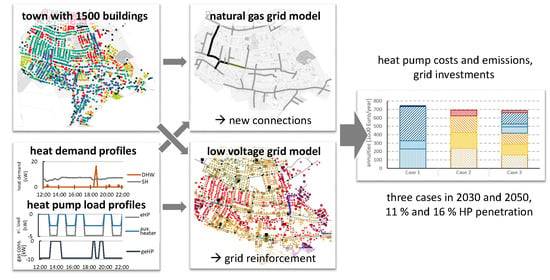
The approach of evaluating the total costs and CO 2 emissions of planning an urban power and gas grid is based on detailed geographic information system (GIS) data. An overview of the different steps is shown in Figure 1. The data used in this study are all publicly available on the Internet as open-data or derived from assumptions based on studies mentioned in the following paragraphs.
The analysis was performed for the German town “Schutterwald” in the geographical region of “Oberrhein” in southern Germany. The basic model of the studied town was built from GIS data of buildings and streets derived from OpenStreetMap (OSM) [53]. Additional information from public sources [54,55] on building age and energetic refurbishment was connected to the buildings of the town. From this geographical connected information, the load profiles and the grid models were derived. All buildings were treated as residential buildings, since commercial buildings are rather rare in the focus area. Most of the town’s commercial and industrial area is located in the northern part of the town, which is not considered in this study. The load profiles cover electrical and thermal profiles. While the electrical load profiles were modeled for each building, thermal profiles were modeled for 12 different building classes with three different renovation standards and five different household types. The electrical load profiles were then geographically connected to the power grid model. The power grid and the gas grid model were also based on GIS data and were modeled based on publicly available information [53,54,55,56,57]. However, assumptions had to be made if the level of detail from the sources was not sufficient. The grids in this study can therefore differ from the actual grid in features such as cable type and exact routing or transformer parameters and location. The thermal profiles served as input for the gas consumption profiles and the future electrical load profiles, which were modeled for the grid planning in 2030 and 2050. The gas and power grid connection point profiles were based on a model of heat pump and storage systems including a rule-based control to apply the thermal energy for space heating and domestic hot water for a household. In future scenarios, additional loads may occur in the grid, e.g., more air conditioning units due to global warming, and electric vehicles. However, these effects are out of the scope of the present study and require further research. From the resulting time-series, the operating costs and CO 2 emissions for the buildings and thermal energy systems on the one hand, and required grid infrastructure investments, on the other hand, were calculated.

2.1. GIS-Based Information

The GIS coordinates of the building were taken from OSM data. The buildings were classified in accordance with the TABULA-building topology for Germany [58,59,60]. Twelve different periods were classified according to their year of construction, as shown in Table 1 (“construction year classes”). The state of energetic refurbishment was modeled by three different states:
  • Variant 1: “standard (no refurbishment).”
  • Variant 2: “moderate refurbishment.”
  • Variant 3: “advanced refurbishment.”
Variant 1 refers to the requirements according to the applicable energy efficiency guideline for buildings in the respective construction year. Moderate and advanced refurbishments differ in thickness of wall insulation, number of insulated walls and other refurbishment measures. A detailed overview is given in [58,59].
The houses’ construction year periods in the example town were derived from the technical report [54]. The result is shown in Figure 2.
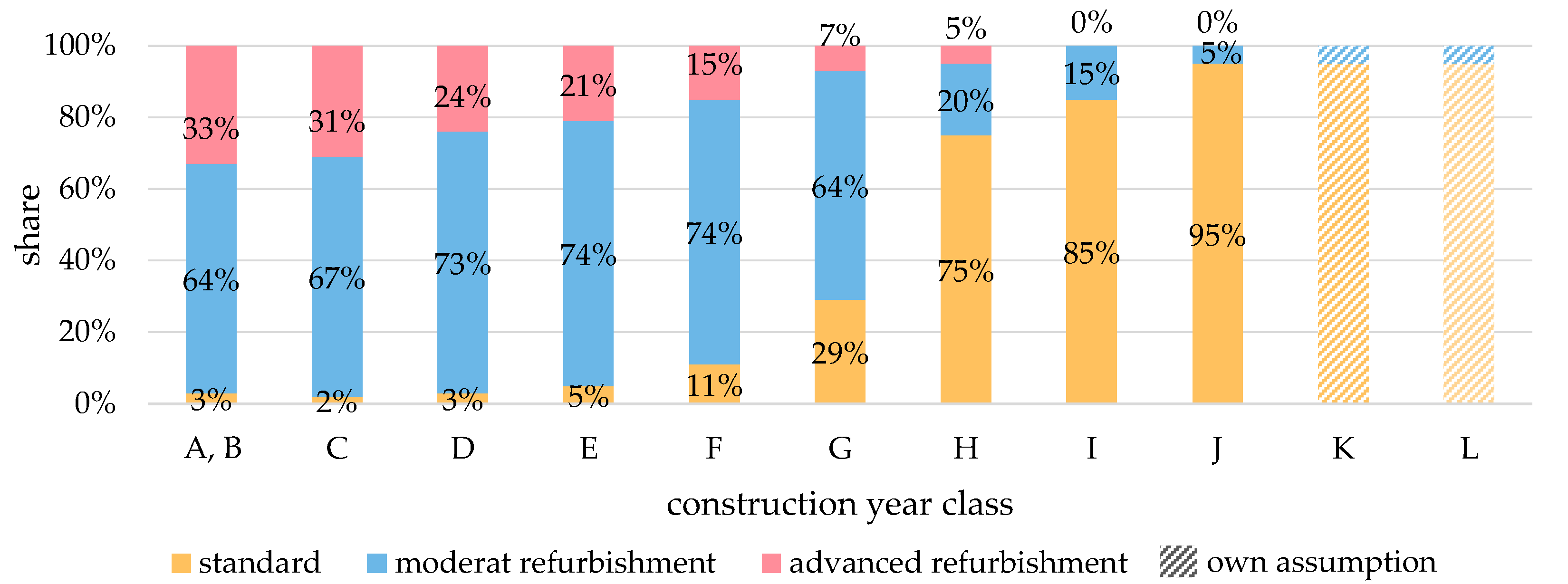
The refurbishment variants were randomly assigned to the houses, based on a probabilistic distribution. The distribution of the three variants within each construction year class was based on statistics of German stock of buildings [55] as depicted in Figure 3. Different household types with one to four residents were randomly assigned to the houses, weighted by the census data for the municipality [61]; see Table 2. The household type is needed to calculate the electrical and domestic hot water load profiles.
In total, the model included 1506 houses; twelve construction year classes with three variants of refurbishment, each completed by five household types.
The temperature and solar radiation data were taken from the weather year 2009.

2.2. Class-Based Electrical and Thermal Load Profiles

To reduce complexity, all buildings were assumed single-family homes. The electrical load profiles without heat generators were generated using a bottom up load profile generator, which is presented in [62]. The profile generator was based on adding up single household devices, such as a television, coffee machine, and washing machine. The devices’ operating times were based on probability functions so that each resulting profile was different from the others. The probability functions were specific for different types of household members, e.g., children use the bathroom lightning earlier in the evening than adults. To account for different usage patterns of electrical appliances and different household sizes, five main household types were implemented representing the statistical distribution of singles (employed/retired) and couples with one, two, or without children in the municipality (Table 2). In total, 2000 different electrical load profiles for one year with a resolution of 10 minutes have been computed using the load profile generator.
Space heating (SH) demand and domestic hot water (DHW) demand were computed using another load profile generator that was developed in [63], similar to the method in [64]. It uses occupation models for the five different household types for each of the 36 building types. The profiles for space heating depending on the construction year class and the domestic hot water demand with a 10 min resolution were also computed for one year. Based on those profiles, models of heat pumps and thermal storage systems were applied to derive “grid connection point profiles”, i.e., electricity and gas load profiles from the heat demand time-series that affect the power grid and natural gas network (see Figure 1).

2.3. GIS-Based Grid Connection Point Profiles

A heating system was modeled by a heat generator unit and two insulated hot water tanks, one for space heating and one for domestic hot water. The distribution of the heat within the house, including radiators, in-house pipes, and ventilation systems, was not modeled explicitly in this study. Distribution losses were taken into account by a loss factor. Three heat generator options were considered to cover the heat demand
  • Natural gas-fired boiler;
  • Electric heat pumps with auxiliary heating coils (eHPs);
  • Gas engine heat pumps (geHPs).
The gas boiler models were based on Equations (1)–(4).
η P n = ( A + B · log 10 ( P n ) ) / 100
η P p a r t = ( C + D · log 10 ( P n ) ) / 100
q P 0 = ( E · P n F ) / 100
P aux = ( G + H · P n K ) / 1000
with rated power P n ; efficiency at rated and partial power η P n and η P p a r t ; standby heat loss q P 0 ; electric auxiliary power P aux ; and factors A–H and K according to standard DIN V 18599:5.
The coefficient of performance (COP) for electric heat pumps ϵ eHP was calculated from the ideal COP and a system efficiency factor η HP = 0 . 36 using Equation (5).
ϵ eHP = T c T c T e · η HP
with temperatures at the condenser T c and evaporator T e in Kelvin.
Like the electric heat pumps, gas engine heat pumps use a refrigerant cycle too. The compressor is driven by a gas engine and the heat from the engine cooling cycle and exhaust gas is utilized by additional heat exchangers. Thus, the overall efficiency was estimated according to Equation (6) with relative exhaust heat loss q ex , loss = 0 . 25 [21], heat pump system efficiency η HP = 0 . 36 and gas engine efficiency η engine = 0 . 307 (assumption: full load, 1400 rpm) [65]. Currently, commercial gas engine heat pumps are only available for rated power of 25 kW upwards but market availability of small-scale geHPs could be reached within a few years [66].
ϵ geHP = 1 q ex , loss + η engine T c T c T e η HP 1
The temperatures of the condensers in houses with regular, advanced, and ambitious energetic standards are assumed to be 55 °C, 45 °C, and 35 °C, respectively. Ambient air temperature records of a nearby weather station were used as evaporator temperature [67]. Since the lowest air temperature in 2007–2014 was recorded for 2009 (−15.2 °C), the weather year 2009 was used for the simulations in this study. Extreme winters may also occur in the future due to changes in atmospheric circulation caused by climate change [68]. Thus, the risk of over-sizing the heating systems appears to be limited but cannot be negated.
The losses of the hot water tanks are calculated with Equation (7) (according to DIN V 18599:5) and the stored heat energy is a function of the tank’s volume and temperature, see Equation (8).
Q loss , d = 0 . 4 kWh day + 0 . 14 kWh 0 . 001 m 3 day · V stor
Q stor = V stor · 1 . 163 Wh 0 . 001 m 3 K · Δ T
with daily heat loss Q loss , d , storage volume V stor in liters, thermal storage capacity Q stor and difference between the maximum and minimum storage temperature Δ T
The investments for heat generators and hot water tanks were estimated according to Equation (9). All price parameters were assumed to stay constant for all investigated scenario years.
C inv = a · X + b
where a and b are factors shown in Table 3 and X is rated thermal power in kilowatts or storage volume in liters [69].
Initial costs were converted to annuities, using an interest rate of i hh = 2 . 7 % for households (average of [70,71,72]) and i DSO = 4 . 27 % for distribution system operators (see Table A9).
The energy carrier rates given in Table 4 were applied to calculate the heating systems’ fuel or electricity costs. Emissions were calculated based on the emission factors given in Table 5 [73,74]. It has to be noted that only scope 1 and 2 emissions were taken into account; no scope 3 emissions (production and mining). Possible emission changes for gas that may come from changing gas mix were neglected.

2.4. GIS-Based Grid Models

Based on the existing building stock model, the town’s low voltage grid and gas distribution network were modeled.

2.4.1. Low Voltage Power Grid Model

As the real low voltage grid of the town is unknown, a new grid model was created. According to the classification presented in [79], three categories are applicable:
  • Synthetic, because it is not based on a real DSO grid model;
  • Example, because the main purpose is to illustrate different scenarios;
  • Benchmark, because it is used to compare different scenarios by derived grid expansion costs.
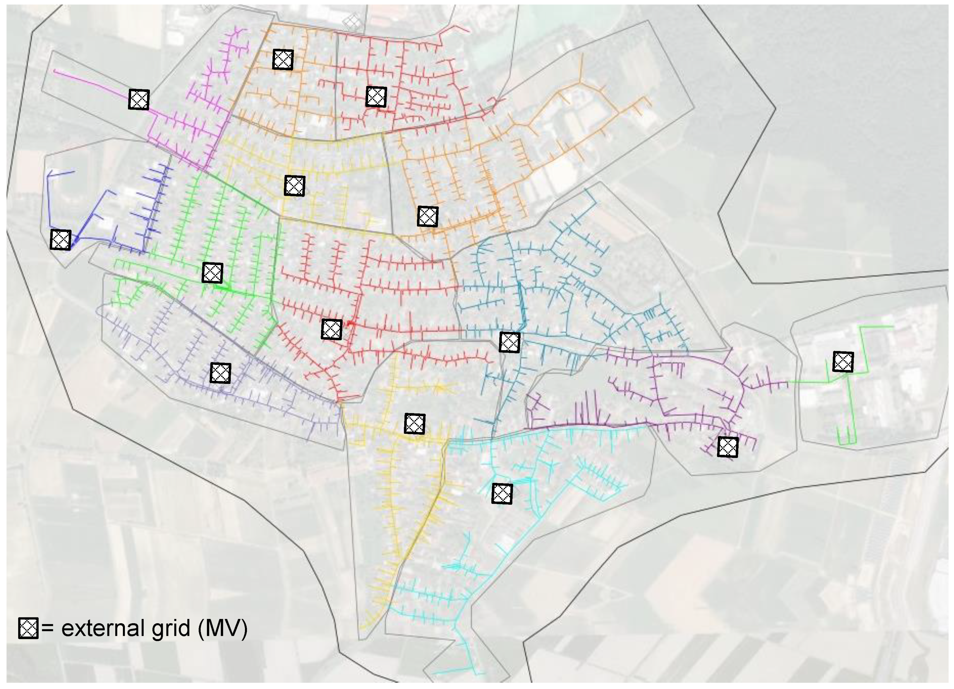
The grid model was derived from an open-source 10 kV medium voltage (MV) grid model called “MV Oberrhein” that is provided as a synthetic grid in the Python package pandapower [32,80]. The low voltage grids for each of the 14 transformers have been modeled using a semi-automated method that includes the following steps:
  • The street lines downloaded from OpenStreetMap are segmented into sets of points with 1 m distance and an individual ID, called grid-points, using the QGIS-plugin QChainage [81]. It is assumed that cables are routed along the streets and each house is assigned to its nearest grid-point using the extension NNJoin [82]. All grid-points that have no house assigned are deleted.
  • The remaining grid-points are connected to their assigned houses by cables of type NAYY 4x50. To derive a preliminary grid structure, grid-points are connected to their nearest neighbor in the same street with less than 40 m distance by cables of the type NAYY 4x150. The parameters and locations of the MV/LV transformer stations are taken from the pandapower grid “MV Oberrhein”. All information is imported to PSS® Sincal to proceed with a graphical interface.
  • The imported information is validated and existing errors due to the automated approach of grid generation are corrected manually. For each transformer, a supply area is chosen and the respective branches are connected by cables of type NAYY 4x150 to the LV-busbar of the transformer. Crossing points of many cables are equipped with switch cabinets. A radial topology without any galvanic connections between transformers is ensured by appropriate switch configuration. The result is shown in Figure 4.
  • For each house, a peak load of P = 2 kW and Q = 0 . 1 kVar is assumed, which represents a c o s ( ϕ ) of 0.96. With these values, a load flow calculation is performed to make sure that the grid model is valid and the voltage and current of each cable, bus, and transformer stay within given limits. Limits are chosen to be 0.9–1.1 p.u. for bus voltages, 60% capacity for cables, and 130% for transformers (oil insulated) [83].
  • If violations of given voltage and capacity limits are found at this stage, switch measure, direct connection to bus bars; or new, parallel cables are added until all restrictions are met.
  • The Sincal-grid model is imported to pandapower and by using the integrated converter of pandapower-pro.
  • The loads in pandapower are connected with the house data (construction year classes, the status of energetic refurbishment, household type) from Figure 2.
  • Time-series of load profiles for each of the 1506 household loads are matched using one of the 2000 generated load profiles.
  • A final load flow calculation for a whole year (all time-steps) is done to validate the grid and make sure all the voltage and currents are within the given limits.
This electrical distribution grid is the benchmark grid for today and was used for the applications of the different scenarios. All transformer tap positions were set to the second-lowest position ( 1 ). The power flow was calculated using the open-source Python package pandapower [32,80]. A version of the synthetic low voltage grid can be found in the Supplementary Materials as a pandapowerNet-file.

2.4.2. Natural Gas Grid Model

The gas distribution grid was modeled in STANET® [84] by applying the following steps:
  • The raw network topology was derived from a map presented in [54].
  • Detailed information such as pipe diameters and types was derived from the gas network operator’s online planning information platform [57] and was set in STANET® accordingly. The backbone of the gas system is made of pipes of the type 180 PE 100; all other pipes are of type 125 PE 100.
  • The location of the city gate station (pressure regulator station) was taken from the route depicted in the land utilization plan [56] and assumed to provide a constant pressure of 1 bar. It was implemented as a constant pressure node in STANET®.
  • The buildings and their types that were set in the electrical distribution grid model were imported to the gas distribution grid model.
  • Linear connection pipes from houses to the nearest natural gas pipeline were created by using the STANET® function “Create house connection pipes”.
  • The STANET® grid model was exported as a CSV-file and imported into pandapipes, an open-source Python package for pipe flow and network simulation [85], for further analysis, e.g., on different lengths of house connection pipes.
  • Gas network capacity tests were conducted to find potential violations of the operation limits (flow velocity and nodal pressure). For these tests, it was assumed that all houses in the model were heated by gas boilers, except for those with an assigned heat pump. Then, time-series simulations were conducted in pandapipes. The highest gas flow velocity and the lowest nodal pressure per time step were logged.
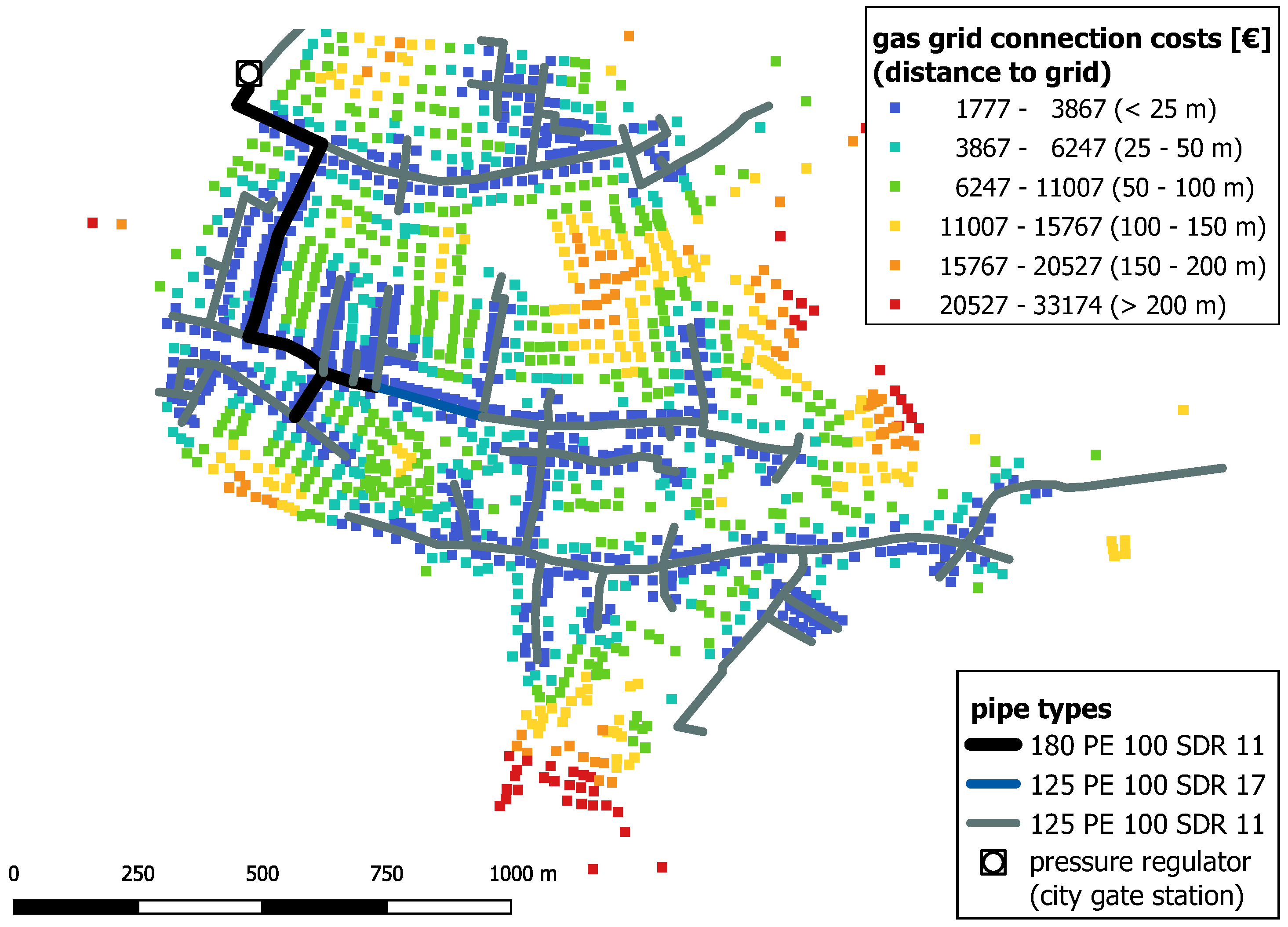
The resulting gas distribution grid is shown in Figure 5 and can be found in the Supplementary Materials in the STANET®-CSV and pandapipesNet-file format.

2.5. GIS-Based Grid Expansion Planning

Based on a scenario data of the INTEEVER project [77] scaled by the number of residents, the numbers of heat pumps in the years 2030 and 2050 were set to 164 and 247, respectively. These heat pumps can be realized as eHPs or geHPs. In the following, three cases are studied and compared for calculating the costs for grid expansion planning of electrical and gas distribution systems.
  • Case 1 “electric”: All heat pumps are realized as eHPs.
  • Case 2 “natural gas”: All heat pumps are realized as geHPs.
  • Case 3 “mixed”: It is assumed that heat pumps are driven by gas engines for houses that are close to the gas grid (less than 67 m linear distance). Heat pumps in other houses are implemented as eHPs.

2.5.1. Allocation of Heat Pumps

Electric heat pumps are connected at the same bus as the household load. For a worst-case scenario, it is assumed that no gas house connections exist or existing house connections are not used. Thus, each geHP is connected to the closest pipe of the gas grid by a linear house connection pipe and pipe investments are required.
The allocation of new heat pumps was not evenly randomly distributed like in other studies but was based on the construction year class. It should also be possible to allocate new heat pumps for a large range of numbers automatically. It should be based on given GIS information and include a sufficient degree of variety to create sets of different samples for the same given number of heat pumps. To achieve this, it was assumed that the likelihood of a house to be equipped with a heat pump depended mainly on the age and degree of refurbishment. For the given stock of buildings, likelihood points were assigned. As heat pumps are especially efficient with modern heating systems that require low-temperature heat, houses with the energetic refurbishment variants “standard”, “moderate” and “advanced”, received 1, 5, and 10 points, respectively. In a second step, today’s shares of heat pumps in each construction year class in Germany were applied and the respective number of houses received 100 points, starting from advanced refurbished houses. For example, 599,201 residential buildings were completed in Germany between 2010 and 2015 (construction year class K), and for 184,110 (30.7%) of those houses, heat pumps were the main heat generator [86]. In the investigated area, around 50 houses got the construction year class K assigned. Thus, 15 of these houses (≈30.7%) received 100 points for the heat pump allocation. The remaining 35 houses stayed at their initial 1, 5, or 10 points. Twenty random allocations were computed for the year 2030 and the remaining heat pumps for 2050 were added subsequently. For replicability, the heuristic’s random number generator was initialized with different seeds (0–19) for each allocation. In each case, the same 20 allocations of heat pumps are analyzed and either electric motors or gas engines were assumed.

2.5.2. Grid Analysis

For each sample grid, power flow and pipe flow calculations were conducted in pandapower and pandapipes/STANET®, respectively. To limit the calculation time, the time-series was reduced to time steps with a cumulative load of 90% or more of the annual peak load. From these time steps, the one with the highest voltage band violation (i.e., lowest bus voltage) was used for the following grid extension study.

2.5.3. Grid Reinforcement

Prior to the low voltage grid reinforcement study, switch measures were applied (i.e., opening and closing of switches) by a hill-climbing heuristic for 5 min to balance line loadings and bus voltages among the network. For this sectioning point optimization (SPO) heuristic, the weighted sum of voltage violations and line overloadings was considered. The weighting factor for voltage band violations was set to 15 and line loading violations were weighted by a factor of 1.5. Then, grid reinforcement and extension measures were applied using hill-climbing and iterated local search algorithms from [33]. The allowed voltage band was 0 . 9 p . u . u bus 1 . 1 p . u . and the maximum line loading was 60%. The following measures were allowed:
  • Replacing overloaded cables or cables that were upstream of voltage band violations by cables with increased diameter (NAYY 4x240).
  • Adding parallel cables (NAYY 4x240) to replaced cables.
Subsets of those measures were evaluated by the heuristic optimizer to find a feasible solution and improve it further towards a cost minimum. However, the solutions might not represent the global minima due to a limited computation time of 30 min. Extension costs for the low voltage grid were estimated based on Table 6.
Table 6. Assumed costs for low voltage (LV) grid extension and construction of natural gas house connections.
ConductorCostsReferenceDepreciation Period
LV cable, NAYY 4x150 mm 2 95,000 EUR/km[87]40 years
LV cable, NAYY 4x240 mm 2 114,000 EUR/kmcalc. from [87,88]40 years
house connection gas pipe, DN 501488 EUR + 95 EUR/m[89]45 years
In the gas grid, the operational limits are specified as minimum node pressure of p min = 20 mbar and maximum gas velocity v gas , max = 18 m / s [90]. If these boundaries are violated, additional pipes have to be considered.

3. Results

In the following, the results for different stages of the bottom-up approach are explained. First, the results for the costs and emissions of single buildings are shown. As the effect of different household types is relatively small compared to the influence of building age and energetic refurbishment, only average values for all five household types are presented. Second, the costs and emissions that were specified for each house type are summarized according to the assumed distribution of buildings with heat pumps. Third, heat maps of bus voltages for worst-case time steps are shown and the calculated required grid investments are given. Finally, the combined costs of heat pumps and grid investments are compared for different cases.

3.1. Costs and CO 2 Emissions for Single Buildings and New Heating Systems

The calculated annual demands for space heating, hot water, and electricity (for household devices, not for eHP) are summarized by household type in the Appendix A, Table A1. The electricity consumption increases with increasing household size. In turn, the space heating demands decrease slightly, due to the waste heat provided by the electrical appliances. The DHW demand is almost proportional to the number of household members. The simulated annual heat production and efficiency values for eHPs and geHPs are listed for each construction year class and energetic refurbishment variant in Table A2 and Table A3. Figure 6 displays specific costs of heat generation for different combinations of heating technologies and years of construction as well as their state of refurbishment. Namely, electric heat pumps with an auxiliary heating coil, gas engine heat pumps, and gas boilers are compared for the construction year classes E (1958–1968) and L (2016 and later). For all heat generator options and years of construction, the required rated heat generator power—and thus the investments—decrease with further energetic refurbishment. Gas boilers have the lowest overall costs of generated heat, as they require the least investments. Required investments for geHPs are 3.18–3.34 times higher than for gas boilers. For eHP, 1.95–3.72 times the investments for respective gas boilers are necessary. Regarding energy costs, geHP are the most cost-efficient, particularly for well-insulated buildings and buildings according to the latest energy efficiency guidelines.
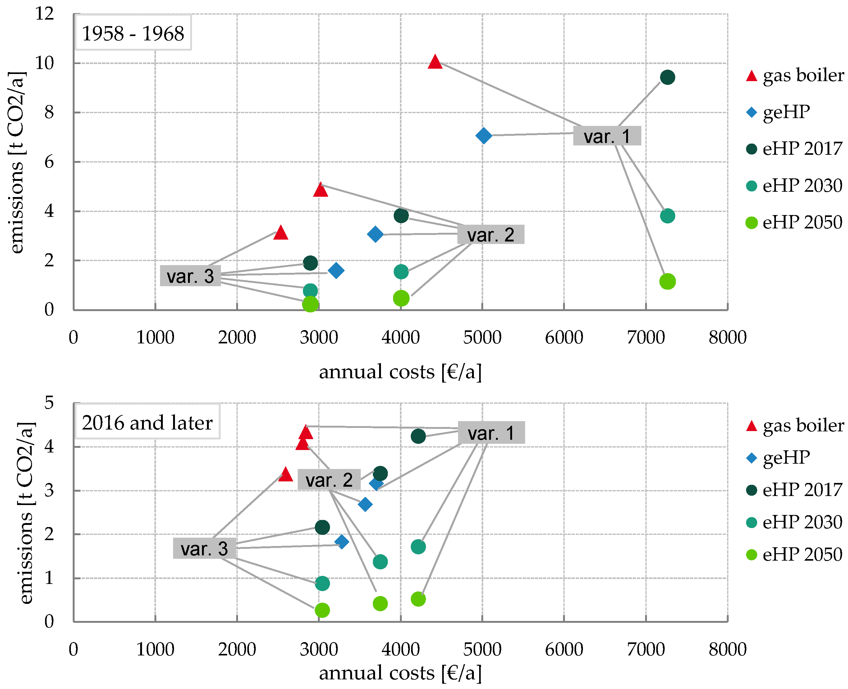
Total annual costs (depreciation, energy consumption, maintenance, and interest) and CO 2 emissions of different heat generators are shown in Figure 7 for the construction year classes E (1958–1968) and L (2016 and later). In all cases, gas boilers cause the highest annual emissions. The replacement of gas boilers by geHPs reduces emissions by 27–30%, 35–37% and 46–49% (for variants 1, 2 and 3, respectively). For eHPs, the assumed electricity mix is essential. Using the electricity mix of 2017, an eHP in a house constructed between 1958 and 1968 would eliminate between 6% (variant 1) and 40% (variant 3) of CO 2 emissions. Assuming a further decline of fossil–fired power plants (see Table 5), the savings rise to 62–76% in 2030 and 89–93% in 2050.

3.2. Cost and Emissions for Investigated Buildings in Schutterwald

The GIS information of the buildings in Schutterwald and the method to allocate new heat pump systems made it possible to calculate the costs and CO 2 emissions for all analyzed buildings in Schutterwald together.
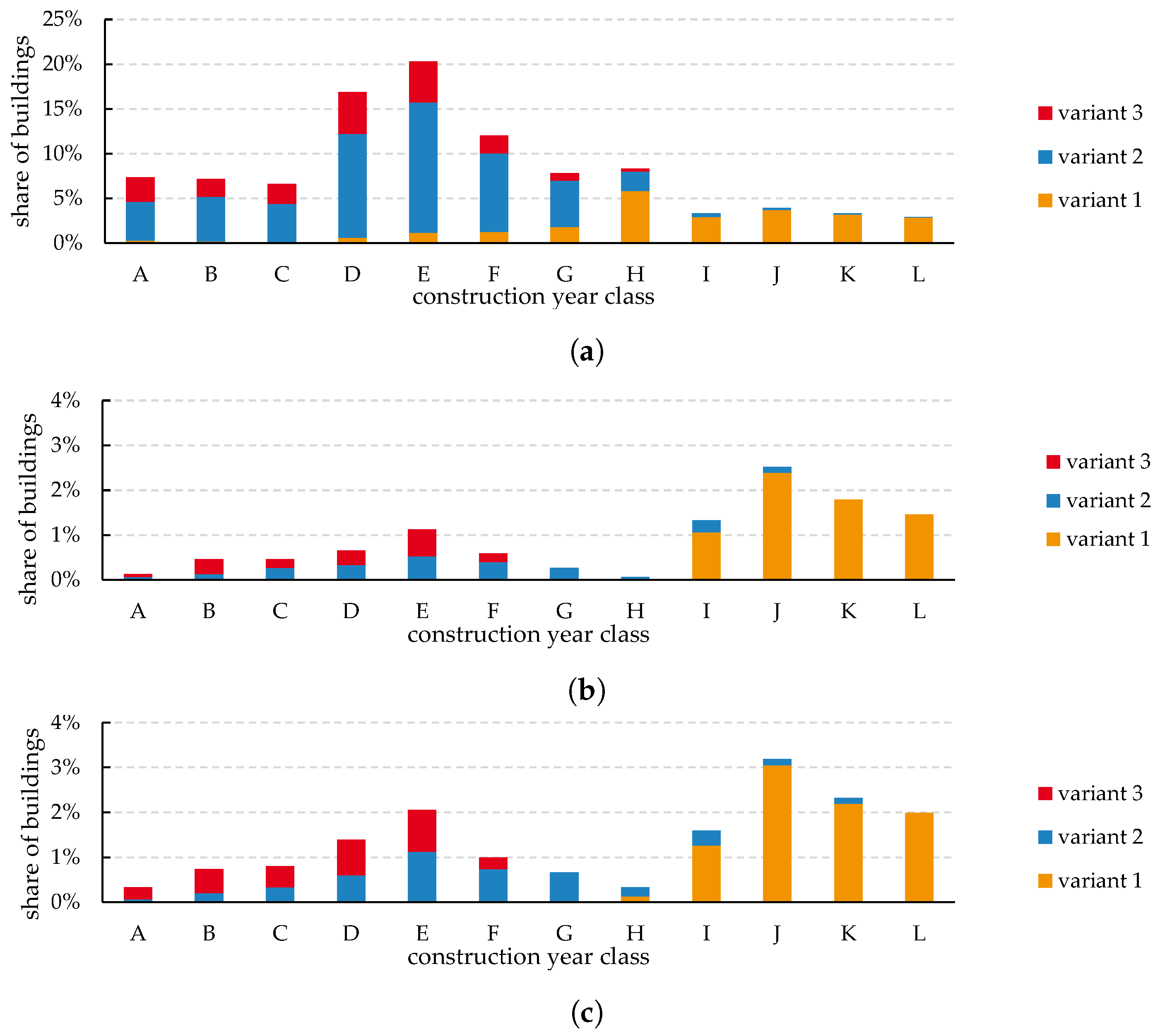
In the investigated cases, 164 and 247 heat pumps were allocated among the 1506 houses of the town. Due to the partially randomized allocation heuristic, the distributions vary among the construction year classes, energetic insulation standards, and household types. The distributions are shown in Figure 8. Figure 8a shows the share of each construction year class and energy refurbishment variant for one exemplary seed. Figure 8b,c present the distributions of heat pumps for 2030 and 2050 respectively.
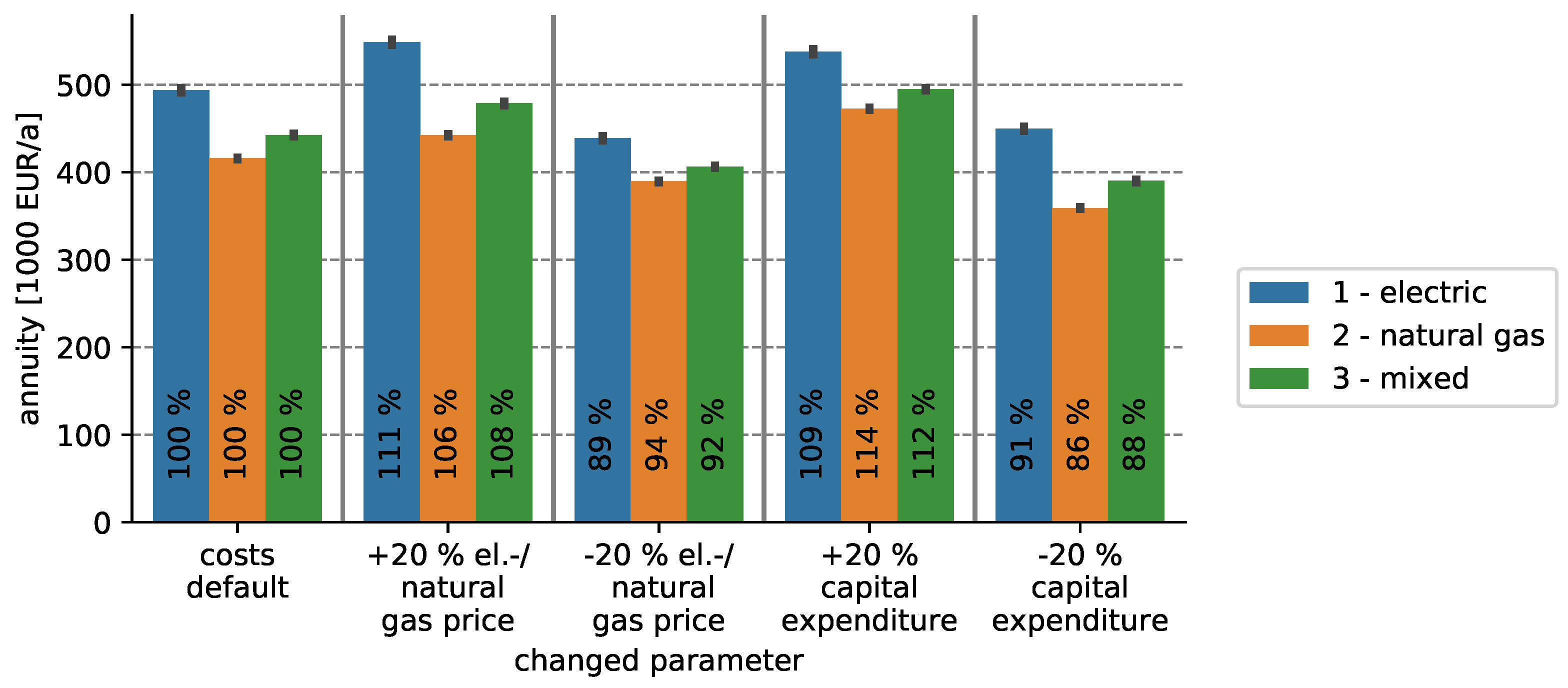
The average total annual costs for 164 heat pumps are 494,000 and 416,000 euros in case 1—electric and case 2—natural gas. For 247 heat pumps, these numbers rise to 736,000 and 624,000 euros. In case 3—mixed, on average 67% of the heat pumps are implemented as geHPs and 33% as eHPs. This is reflected proportionally in the heat pump investments and energy costs of 443,000 and 662,000 euros for 164 and 247 heat pumps in case 3. In Figure 9, the cost sensitivity to varied energy prices and investment costs is depicted. In case 1, an electricity price increase of 20% leads to raised overall costs of +11%. If the electricity price is lowered by 20%, case 1 has lower heat pump costs than case 3 with default parameters (−2.2%). If required heat pump investments change by 20%, the overall annuities change by 9%, 12%, and 14% in cases 1, 2, and 3, respectively.
The heat pumps’ cost difference is relatively small compared to the difference in annual CO 2 emissions. In the 2030 scenario, the heat pumps emit on average 505 t CO 2 - eq /a if they are implemented as geHPs. In contrast, the same number of eHPs in 2030 causes on average 66% less CO 2 . With decreasing carbon intensity of the electricity mix, this difference rises to 84% less CO 2 from eHPs than from geHPs in 2050. The emissions in case 3 scale proportionally to the respective eHP/geHP ratio.

3.3. Required Grid Investments in the Gas and Power Grids

For each allocation of heat pumps, sectioning point optimizations were conducted in the electric and mixed cases. If voltage band violations or line loading violations occurred, grid reinforcement measures were added.

3.3.1. Case 1—Electric (eHPs)

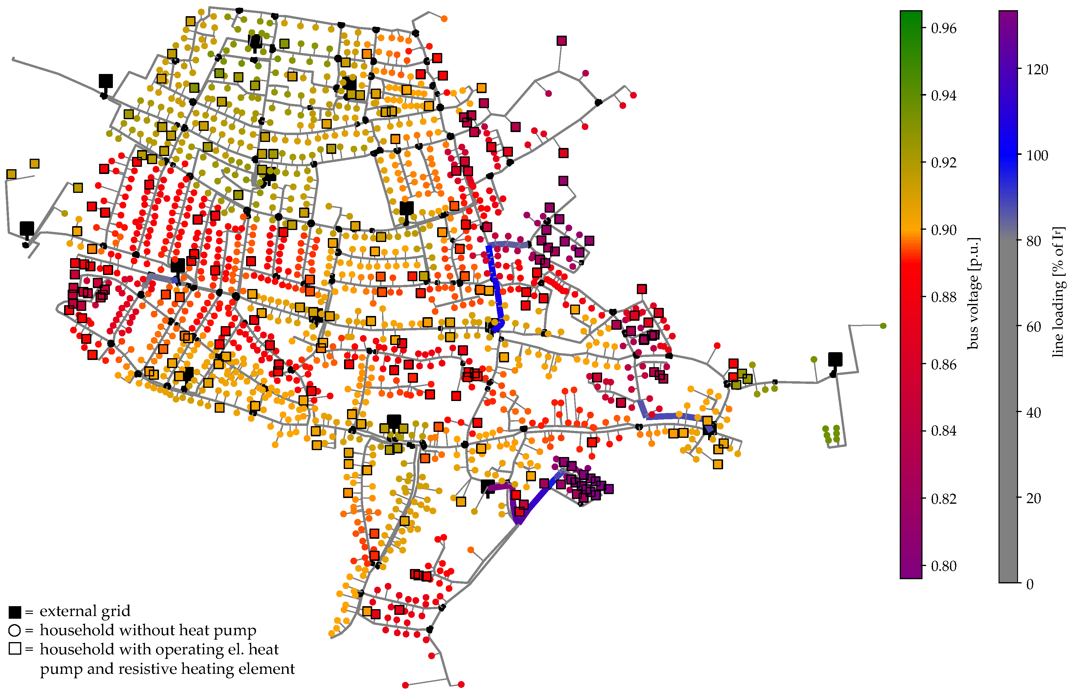
From the sample allocation of 247 heat pumps shown in Figure 10, it can be confirmed that the distribution among the town’s houses is not equal, due to the weighted random heuristic. Thus, clustering can be observed in areas with younger buildings, in the western and southeastern part of the town. In these areas, the grid load is particularly high. Table 7 gives an overview of lowest bus voltages and maximum line loads for an exemplary allocation (for the seed “15”). Undervoltage occurs at 54% of the busses but can be reduced to 4.8% of the buses by SPO; 68 lines (1.66 km) are overloaded; that is, 5.0% of the total low voltage line length without house connection cables. The results show that the violations can be significantly lowered by SPO. If the solutions of the automated grid reinforcement planning are applied, all voltage and line loading limits are met.
The required grid extension measures differ highly between different seeds and the success of the automated grid extension hill-climbing heuristic.
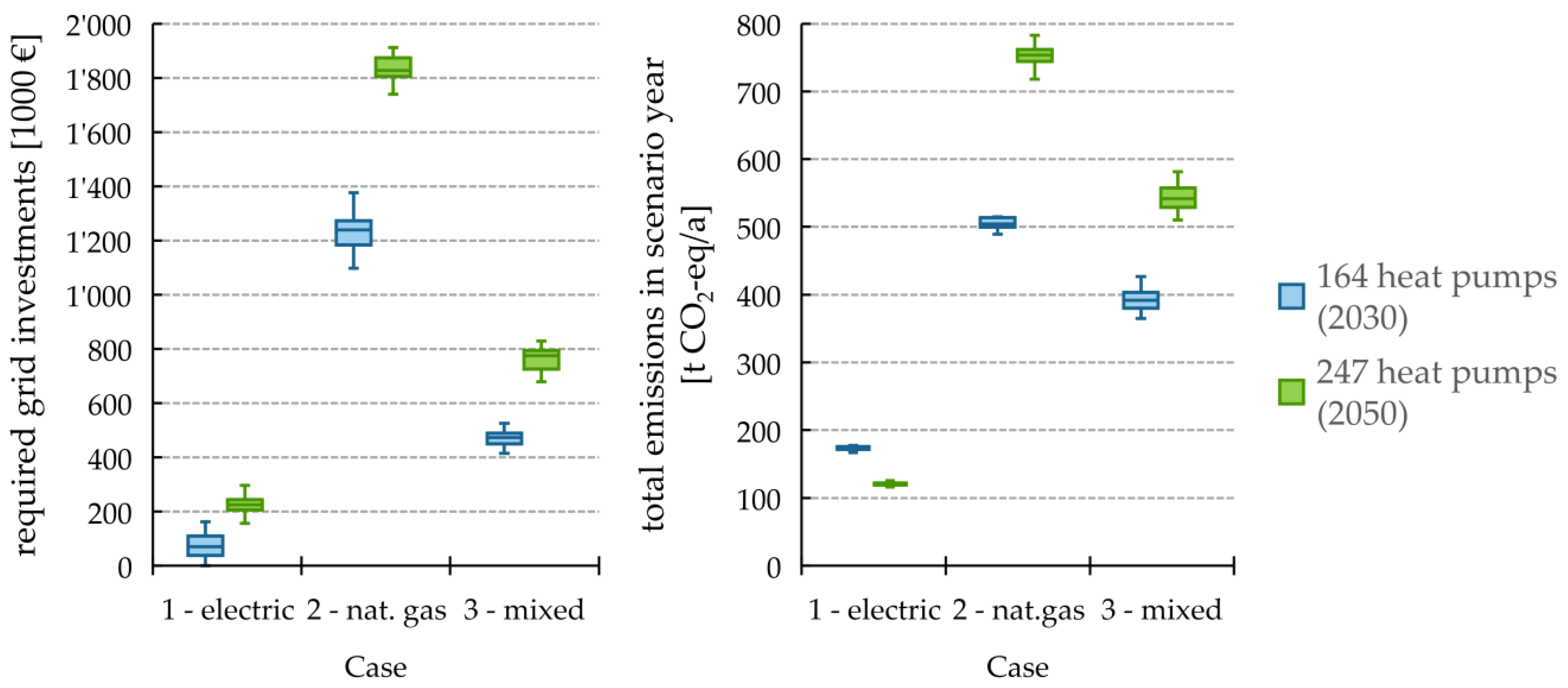
For some seeds, very few measures are required or sectioning point optimization was already sufficient to meet all operational restrictions. Overall, the maximum required grid reinforcement investments summed up to 161,994 euros in 2030 and 296,419 euros in 2050 with average costs per allocation of 76,110 euros (2030) and 223,488 euros (2050).

3.3.2. Case 2—Natural Gas (geHP)

In this case, the same heat pump allocations as in case 1 were evaluated, but gas engines were assumed instead of electric motors. The required gas connection pipes differ in length and were not limited in this case. As shown in Figure 5, the majority of the town’s houses are closer than 100 m to the natural gas grid. However, some areas are further away and the longest required connection pipe has a length of 332.8 m.
This leads to higher grid investments than in case 1 with on average 1,237,127 euros in 2030 and 1,829,862 euros in 2050. These values are theoretical values and indicate an upper limit, as all pipes are implemented as connection pipes. In a real system, the main distribution system may be expanded to supply new demand areas. Thus, shorter house connection pipes would be necessary.
The capacity test shows maximum gas velocities of 13.5 m/s and nodal pressures between 0.80 bar and 1.00 bar in case 2 with 247 geHPs and gas boilers for the remaining 1259 houses. Thus, no predefined operating limits are violated and no reinforcement or extension of the natural gas network is required apart from house connection pipes.

3.3.3. Case 3—Mixed (eHPs and geHPs)

In case 3, both electric and gas engine heat pumps should be deployed. As a reasonable indicator to estimate the house owners’ preference for one technology or the other, the house’s distance to the gas grid and the respective connection costs were used. For young houses (construction year class L-2016 and later, variant 1) the net present value for heat supply over 20 years is −64,706 euros for eHP and −56,819 euros for geHP, not including connection pipelines. The difference, 7887 euros, equals the costs for a natural gas house connection pipe of 67.2 m length. Thus, this distance is considered as a threshold in case 3.
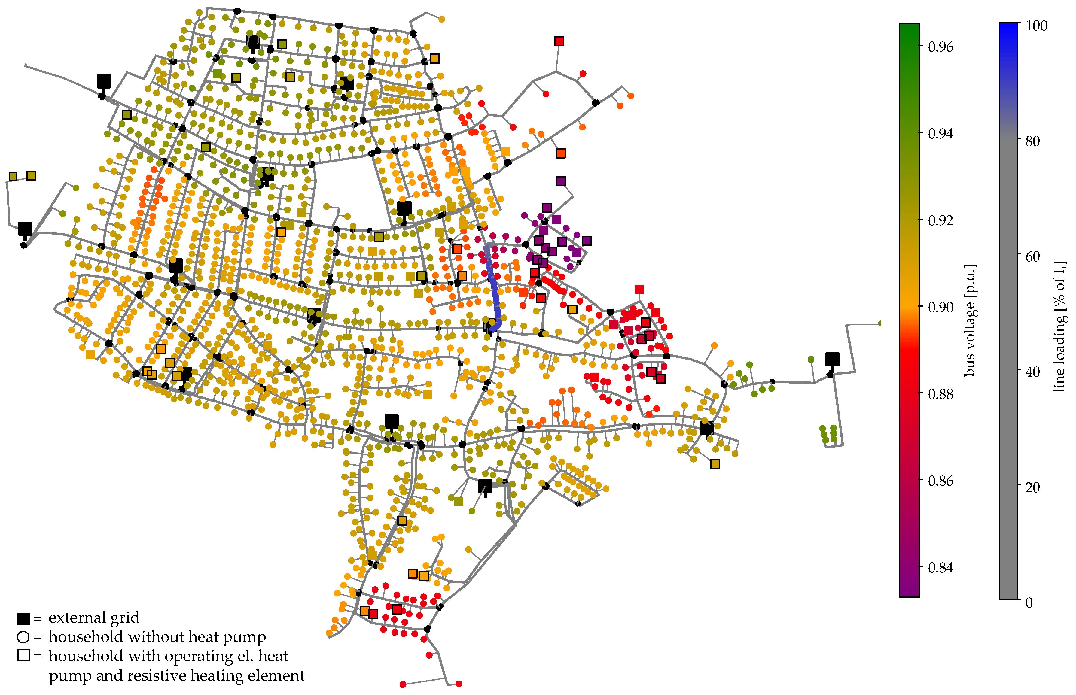
As in cases 1 and 2, the same allocations of heat pumps were used in case 3. It was assumed that all heat pumps that were closer to the gas grid than 67 m were driven by gas engines (geHPs). Those heat pumps that were further than 67 m away from the existing natural gas network were assumed electrically driven (eHPs). Since the electrical load was reduced (compared to case 1), large parts of the power grid were without violations. However, some load clusters remained and required grid reinforcement (Figure 11). In general, the violations of the admissible voltage range and the maximum admissible line loads were lower than in case 1. In addition, sectioning point optimization can reduce maximum voltage violations more effectively than in case 1 (see Table 7). On average, this leads to reduced low voltage grid investments of 45.4% (2030) and 33.8% (2050) compared to case 1. At the same time, 35.4% (2030) and 37.2% (2050) of the investments in gas grid connection pipes calculated in case 2 are required.

3.4. Combined Costs of Heat Supply and Grid Investments

All grid extension and grid connection costs are summarized in Table A7 and shown in Figure 12.
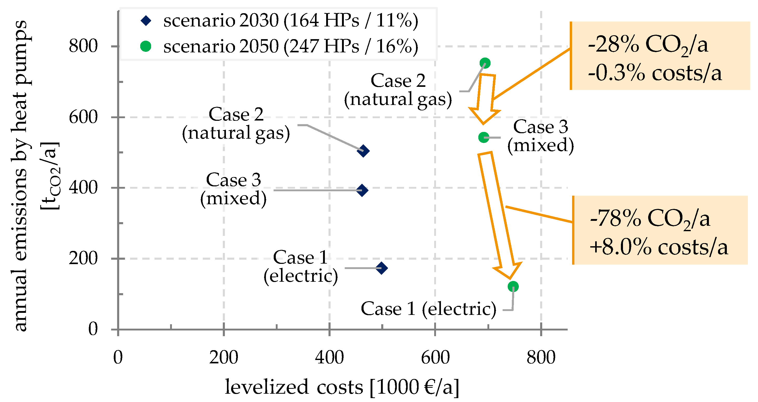
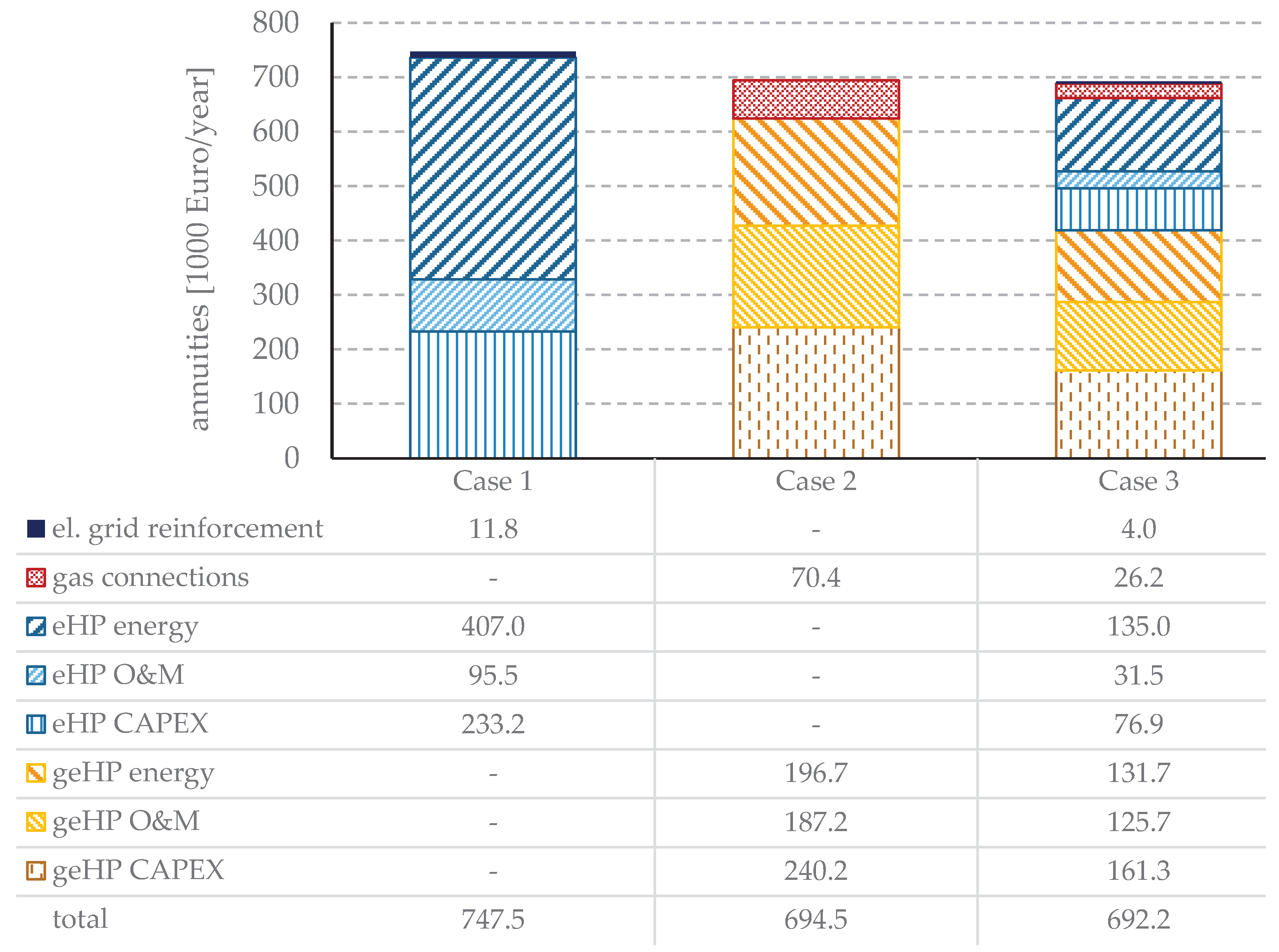
The combined costs of required grid investments per case and heat pump investments, maintenance, and operation are shown with the average emissions in 2030/2050 in Figure 13. For comparison, all costs and investments have been converted to annuities, as installed cables and pipes have much longer lifetimes than heat pumps (see Table 3 and Table 6). In all three cases, the required grid investments are low compared to the heat pump related costs. In the scenario with 247 heat pumps, the highest shares of grid investments are 2.1%, 10.6%, and 4.7% for cases 1, 2, and 3, respectively. The average grid investments and other cost components for each case are shown in Figure 14.
In case 2, the cost advantage of geHPs (Table A6) caused by lower energy costs is to a large extent compensated by the higher grid investments. On average, the overall annual costs of case 2 (gas) are 7% lower than in case 1 (electric), both in 2030 and 2050. In case 3 (mixed) a decrease in costs of 0.5% occurs, compared to case 2. The CO 2 -emissions of case 2 are by a factor of 2.9 (2030) and 6.3 (2050) higher than in case 1.

4. Summary

4.1. Conclusions

Amongst others, three innovation highlights were addressed in this paper:
  • On the basis of a large number and different types of public data only, a low voltage and gas grid model with a highly diversified spatial resolution has been created for an example town and made available in the Supplementary Materials.
  • We did a mutual investigation of power and natural gas distribution infrastructure for a whole town using a pipe and power-flow grid analysis.
  • For all three cases, we investigated grid investments, heat pump costs, and CO 2 emissions for a multi-perspective approach.
A low voltage network for a town with around 1500 houses has been modeled in pandapower. In addition, a simplified but realistic natural gas distribution network model has been developed in STANET® for the same town. A model of the existing building stock of the town has been derived from OpenStreetMap coordinates and has been enriched with realistic data on construction year classes. Furthermore, information on the houses’ energetic refurbishment and household types has been estimated based on detailed statistics. For each house type, different heat demand profiles were simulated and electric load profiles for heat pumps as well as natural gas load profiles for gas boilers and gas engine heat pumps have been derived. Overall, the models can be seen as synthetic with realistic assumptions. They have been compared in terms of costs and emissions. For the majority of the investigated buildings, it was found that eHPs caused higher specific CO 2 -emissions than geHP in 2017. In 2030 and 2050 scenarios, however, the eHP emissions were around 50% and more than 80% below the geHP emission levels, respectively. The specific heat generation costs for eHP decrease strongly with the increasing energetic refurbishment of the buildings. For buildings with little to no energetic refurbishment, a cost advantage for geHP was observed.
Based of the load profiles, the effects of heat pump deployment on either energy infrastructure have been analyzed regarding required grid reinforcement and extension measures. In the power grid, a large share of bus voltage violations could be solved by SPO, which switches lines from one branch to another. If around 11% of the buildings are equipped with electric heat pumps, little to no grid reinforcement is required in the investigated model. For gas engine heat pumps, however, significant grid connection costs can occur if the maximum connection length is not limited. If the share of heat pumps rises to 16%, bigger clusters occur, and average required grid investments in the low voltage power grid increase. Nonetheless, the electric heat pump case (case 1) requires just 12% of the grid investments in the gas engine heat pump case (case 2) and causes 84% less CO 2 emissions (in 2050). If heat pump investments and operating costs are considered as well, case 3 comes on average with 0.3% less annual costs and −28% CO 2 emissions in 2050 compared to case 2. If all remaining geHPs in case 3 are replaced by eHPs, overall annual costs increase on average by 8.0% and CO 2 emissions decrease by 78% (see Figure 13). The observed load clusters indicate the importance of a neighborhood’s building characteristics (e.g., energetic refurbishment and age) for grid planning and energy system modeling.

4.2. Discussion and Limitations

In the proposed method, multiple building characteristics (construction year, energetic refurbishment, household type) are taken into account. The grid load analysis indicates that the degree of energetic refurbishment has the strongest effect of grid stress. This is partly related to the assumption of decreasing heating temperatures with higher insulation but also shows the importance of energy efficiency.
In the case study, some simplifications and assumptions were made that may have affected the results. In particular, constant cost parameters due to neglected learning curves may have led to overestimated investment costs for heat pumps. Additionally, the fact that present heat generators and existing gas grid connections were not taken into account also led to higher cost estimations. Instead of adding multiple individual house connection gas pipes, synergies could be used by extending the main natural gas grid to reach new demand clusters. For this, the gas grid could be modeled in pandapipes and an algorithm similar to the automated grid planning in pandapower [33] could be applied.
The buildings’ heat demand was likely overestimated as well since the building stock was assumed to stay constant and no refurbishments were taken into account. The distribution of the heat within the house included radiators, in-house pipes, and ventilation systems. These systems were not modeled explicitly in this study, but are important within the context of renovation and usability of thermal systems with different temperature levels. Therefore, it is important to distinguish between old buildings with low refurbishment standards and new buildings with low heat demand. Enabling older buildings to use electrical heat pump systems could create much higher costs than in younger buildings.
This work focuses on single-family homes. However, commercial, non-residential consumers will likely have a strong impact on load in the power and natural gas grids. There are commercial consumers, such as restaurants, cooking with natural gas, who may not be willing to change to electrical systems. Solutions for such individual demands have to be taken into account in real urban systems. As the natural gas composition was assumed to stay constant, the emissions were higher than in a scenario with an increased share of green hydrogen, bio-methane, or synthetic fuel usage. Nevertheless, for a comprehensive assessment of the emissions, supply chain emissions of electricity generation and natural gas supply have to be taken into account as well. This could lead to remarkably higher indirect emissions. Traber and Fell [91] reported a global warming potential (20-year horizon) of the natural gas supply chain of 170–337 g CO 2 - eq /kWh fuel . Compared to scope 1 emissions of 202 g CO 2 /kWh fuel , this implies an increase of emissions by 84–266%.
In addition, the investigated cases did not consider other developments that may increase the need for grid reinforcement. In particular, increasing installations of solar PV, charging points for electric vehicles, and the need for air conditioning units can be considered as potential drivers for additional power grid investments.
The grid extension analysis was conducted for a dedicated town with specific infrastructure and building stock characteristics. Therefore, the applied method will likely lead to different results in other towns and further research is required to derive more general results.

4.3. Further Research

The calculations were done for a synthetic German town example and the numbers of new heat pumps were taken from a national energy optimization model. However, the number was rather low, so that 11% and 16% of the buildings were to be equipped with heat pumps in 2030 and 2050, respectively. This leaves questions regarding efficient, renewable heating systems for the rest of the buildings in the town. In Germany, the new installation of decentralized oil heating systems will be forbidden, starting in the year 2025. Currently, more than 60% of the buildings in the example town are equipped with such systems. An evaluation of cost and feasibility needs to be done for future scenarios, including the change of all thermal supply systems in the town to a CO 2 neutral solution.
In this study, a simple control algorithm for heating systems has been used and static blocking time slots set by the DSO were assumed. Advanced algorithms may lead to further variation in load profiles and thus reduce simultaneity. This would lead to lower peak load and reduce required grid extension measures. Furthermore, future research may check the usage of small-scale heat pumps for each building against the possibility of installing district heating grids.
The matching power and gas grid models that were created in this work can be used for future research, in particular in the field of coupled power and gas distribution grids.
For municipalities with increasing numbers of heat pumps being installed, the case study provides an initial impression in which operating costs, capital expenditures for households, and grid operators arise and how they are distributed among the stakeholders. As a next step, the individual stakeholders’ investment decisions could be investigated in more detail and policy measures (e.g., regional incentive programs) could be coordinated accordingly. However, the results of the case study cannot be generalized without further research.

Supplementary Materials

The following network models are available online at https://www.mdpi.com/1996-1073/13/16/4052/s1: natural gas network in pandapipes-JSON format (pandapipes version 0.1.2), natural gas network in STANET-CSV format, and low voltage power grid in pandapower-JSON format (pandapower version 2.2.2).

Author Contributions

Conceptualization, T.M.K. and J.M.K.; methodology, J.M.K.; software, J.M.K.; formal analysis, J.M.K.; investigation, J.M.K.; data curation, J.M.K.; writing—original draft preparation, T.M.K. and J.M.K.; writing—review and editing, M.B. and S.L.; visualization, J.M.K. and T.M.K.; supervision, T.M.K. and S.L.; project administration, T.M.K.; funding acquisition, T.M.K. All authors have read and agreed to the published version of the manuscript.

Funding

This research was funded by the Bundesministerium für Wirtschaft und Energie within the projects INTEEVER and INTEEVER II (03ET4020C and 03ET4069C).

Acknowledgments

J.M.K. would like to thank Daniel Then (Fraunhofer IEE, Stadtwerke Bamberg GmbH) for his helpful advice on low voltage network planning. The authors thank bnNETZE for permission to use the natural gas grid data.

Conflicts of Interest

The authors declare no conflict of interest. The funders had no role in the design of the study; in the collection, analyses or interpretation of data; in the writing of the manuscript, or in the decision to publish the results.

Abbreviations

The following abbreviations are used in this manuscript:
aux.auxiliary
CAPEXcapital expenditure
CHPcombined heat and power
cons.consumption
constr.construction
COPcoefficient of performance
DHWdomestic hot water
DSOdistribution system operator
eHP, eHPselectric heat pump, electric heat pumps
el.electricity
EMFemission factor
geHP, geHPsgas engine heat pump, gas engine heat pumps
Hh., hhhousehold
NZEBnearly zero-energy building
O&Moperation and maintenance costs
OSMOpenStreetMap
prod.production
PVphotovoltaic
SHspace heating
WACCweighted average cost of capital
YTMyield to maturity

Appendix A. Supplementary Tables

Table A1. Simulation results for average (by household type) annual space heating demand, domestic hot water demand, and electricity consumption of household devices. For each household type, 12 construction year classes with 3 energy refurbishment variants each were considered.
Household TypeSpace Heating [kWh th ]DHW [kWh th ]El. Hh. Devices [kWh el ]
single, employed19,6188472263
single, retired19,5798691912
couple, employed, no children18,62017073281
couple, employed, 1 child17,82725784207
couple, employed, 2 children16,92334554842
Table A2. Calculated electricity consumption, heat generation, and efficiency of eHP systems for different types of single-family homes (average of the five household types).
Constr.
Year Class
Energy
Refurb.
Variant
Heat
Demand
[kWh/a]
El. Cons.
eHP
[kWh el /a]
Heat Prod.
eHP
[kWh th /a]
Annual
COP
(eHP Only)
El. Cons. Aux.
Heating Coil
[kWh el /a]
Annual COP
(System of
eHP + Coil )
A166,97530,72573,4222.3918562.31
222,812884726,0822.957392.80
313,557411616,0513.904883.59
B140,96519,24446,2072.4011642.32
215,088603517,9382.974992.82
39667303012,0273.973723.64
C159,07627,18465,0142.3916792.31
229,10211,28733,2192.949222.80
319,762585722,5553.857123.54
D132,67415,40337,1452.418842.33
214,130567816,9422.984262.85
37991257710,3114.002873.70
E135,02616,58239,9292.419762.33
216,639657719,5542.975492.82
310,125315912,5173.963843.64
F136,59417,14241,2382.4110432.33
217,809704120,7962.955682.81
312,543384315,0333.914913.58
G129,90214,12634,0502.418532.33
217,219680320,1662.965722.81
312,327378214,8433.924743.60
H124,72811,81028,4762.416742.34
216,176642819,0712.975282.82
310,589329812,9643.933933.62
I115,938782118,9972.434602.35
213,400545316,2522.984132.84
39116286511,3963.983673.64
J113,988693216,8582.434362.35
212,678516815,4873.004042.85
310,318319312,6833.973863.65
K118,232883921,4192.425282.34
216,358651319,3212.975192.82
311,788363114,3353.954423.63
L115,178744818,1402.444442.35
214,490582617,3312.974822.82
311,611360214,1663.934233.62
Table A3. Calculated natural gas consumption, heat generation and primary energy ratio (ratio heat output/fuel input) of geHP systems for different types of single-family homes (average of the five household types).
Constr.
Year Class
Energy
Refurb.
Variant
Heat
Demand
[kWh/a]
Fuel Cons.
[kWh fuel /a]
Heat
Prod.
[kWh th /a]
Primary
Energy
Ratio
A166,97560,18975,5241.25
222,81218,57526,4781.43
313,557951416,4511.73
B140,96537,22446,7701.26
215,08812,63318,1481.44
39667689312,0071.74
C159,07653,21466,8171.26
229,10223,61533,5901.42
319,76213,69223,4201.71
D132,67429,57937,2501.26
214,13011,76816,9421.44
37991571599701.74
E135,02631,76039,8941.26
216,63913,78719,7991.44
310,125720512,5311.74
F136,59433,18341,7601.26
217,80914,78821,1651.43
312,543887815,3521.73
G129,90227,10534,0961.26
217,21914,34220,5911.44
312,327868615,0031.73
H124,72822,61428,4951.26
216,17613,43319,2521.43
310,589750112,9831.73
I115,93814,92818,8941.27
213,40011,23716,1381.44
39116655311,4701.75
J113,98813,24316,7841.27
212,67810,66115,3531.44
310,318727512,6851.74
K118,23216,93721,4041.26
216,35813,60819,5231.43
311,788828714,3891.74
L115,17814,21918,0391.27
214,49012,06917,3061.43
311,611820914,2241.73
Table A4. Annual costs (CAPEX, O&M, fuel) in euros/year and emissions in t CO 2 - eq /year for different heat generators in a single-family home, construction year period E (built between 1958 and 1968).
Existing State
(Var. 1)
Usual Refurbish-
ment (Var. 2)
Adv. Refurbish-
ment (Var. 3)
Information: EMF
[g CO 2 /kWh fuel ]
CostsEmissionsCostsEmissionsCostsEmissions
oil boiler531113.733866.627144.1266
gas boiler487310.831975.026253.2202
geHP53207.537983.132631.6202
eHP 2017780910.941964.329832.1537
eHP 203078094.441961.729830.9141
eHP 205078091.341960.529830.366
Table A5. Annual costs (CAPEX, O&M, fuel) in euros/year and emissions in t CO 2 - eq /year for different heat generators in a single-family home, construction year period L (built in 2016 or later).
National Minimum
Requirement
(Var. 1)
Ambitious Standard/
NZEB
(Var. 2)
Advanced Refurbishment
(Var. 3)
Information: EMF
[g CO 2 /kWh fuel ]
CostsEmissionsCostsEmissionsCostsEmissions
oil boiler31465.731145.628184.5266
gas boiler29874.529624.327133.5202
geHP38093.236692.833451.9202
eHP 201744124.739263.831462.4537
eHP 203044121.939261.631461.0141
eHP 205044120.639260.531460.366
Table A6. Statistical description of overall annualized heat pump investments and yearly energy costs in 1000 euros/a for each case (20 allocations per case). Q 1 , Q 2 , and Q 3 represent 25%, 50%, and 75% quartiles.
YearNumber of Heat PumpsCaseMean σ MinQ 1 Q 2 Q 3 Max
20301641 - electric4946480491494500502
2 - natural gas4163411415416419419
3 - mixed4433438440442446448
20502471 - electric73611707730737741759
2 - natural gas6245613622624627634
3 - mixed6626646659663667672
Table A7. Statistical description of required natural gas and low voltage grid investments in 1000 euros for each case (20 different allocations per case).
YearNumber of Heat PumpsCaseMean σ MinQ 1 Q 2 Q 3 Max
20301641 - electric764603869109162
2 - natural gas12377410971184123812731376
3 - mixed47330415450472489526
20502471 - electric22336157205225244296
2 - natural gas1830461740180518281,8731912
3 - mixed75744679725775794829
Table A8. Statistical description of annual CO 2 emission caused by heat pumps in the scenarios in t CO 2 - eq /a.
YearNumber of Heat PumpsCaseMean σ MinQ 1 Q 2 Q 3 Max
20301641 - electric1733167172173176177
2 - natural gas5058489501504513515
3 - mixed39216365380392403427
20502471 - electric1202114119121122125
2 - natural gas75314718745753761783
3 - mixed54319510530542557582
Table A9. Discount rate assumptions.
ParameterValueReference
discount rate households2.67 %average of [13,71,72]
equity interest rate DSO6.91 %[92]
debt interest rate DSO1.33 %10 year avg. of YTM on German bearer debentures (2009–’18) [93]
equity ratio DSO52.73 %[94]
discount rate DSO (WACC)4.27 %own calculation

References

  1. European Parliament; Council of the European Union. Directive (EU) 2018/2002 of the European Parliament and of the Council of 11 December 2018 amending Directive 2012/27/EU on energy efficiency. Off. J. Eur. Union 2018, 328, 210–230. [Google Scholar]
  2. Erbach, G. Understanding Energy Efficiency; European Parliamentary Research Service: Brussels, Belgium, 2015. [Google Scholar]
  3. German Federal Ministry for the Environment, Nature Conservation, Building and Nuclear Safety (BMUB). Climate Action Plan 2050: Principles and Goals of the German Government’s Climate Policy; BMUB, Division KI I 1: Berlin, Germany, 2016.
  4. Federal Ministry for Economic Affairs and Energy (BMWi). The Energy of the Future: Second Progress Report on the Energy Transition. Reporting Year 2017; BMWi, Public Relations Division: Berlin, Germany, 2019.
  5. Fraunhofer IWES; Fraunhofer IBP. Heat Transition 2030; Agora Energiewende: Berlin, Germany, 2017. [Google Scholar]
  6. von Appen, J. Sizing and Operation of Residential Photovoltaic Systems in Combination with Battery Storage Systems and Heat Pumps: Multi-Actor Optimization Models and Case Studies. Ph.D. Thesis, University Kassel, Kassel, Germany, 2018. [Google Scholar]
  7. von Appen, J.; Braun, M. Sizing and improved grid integration of residential PV systems with heat pumps and battery storage systems. IEEE Trans. Energy Convers. 2019, 34, 562–571. [Google Scholar] [CrossRef]
  8. Scheidler, A.; Bolgaryn, R.; Ulffers, J.; Dasenbrock, J.; Horst, D.; Gauglitz, P.; Pape, C.; Becker, H. DER Integration Study for the German State of Hesse—Methodology and Key Results. In Proceedings of the 25th International Conference on Electricity Distribution, Madrid, Spain, 3–6 June 2019; CIRED: Madrid, Spain, 2019; pp. 1–5. [Google Scholar] [CrossRef]
  9. Guelpa, E.; Bischi, A.; Verda, V.; Chertkov, M.; Lund, H. Towards future infrastructures for sustainable multi-energy systems: A review. Energy 2019, 184, 2–21. [Google Scholar] [CrossRef]
  10. Mancarella, P. MES (multi-energy systems): An overview of concepts and evaluation models. Energy 2014, 65, 1–17. [Google Scholar] [CrossRef]
  11. Prina, M.G.; Manzolini, G.; Moser, D.; Nastasi, B.; Sparber, W. Classification and challenges of bottom-up energy system models—A review. Renew. Sust. Energ. Rev. 2020, 129, 109917. [Google Scholar] [CrossRef]
  12. D’Agostino, D.; Mazzarella, L. What is a Nearly zero energy building? Overview, implementation and comparison of definitions. J. Build. Eng. 2019, 21, 200–212. [Google Scholar] [CrossRef]
  13. Ifeu, Fraunhofer IEE, Consentec. Building Sector Efficiency: A Crucial Component of the Energy Transition; Agora Energiewende: Berlin, Germany, 2018. [Google Scholar]
  14. Webb, A.L. Energy retrofits in historic and traditional buildings: A review of problems and methods. Renew. Sust. Energ. Rev. 2017, 77, 748–759. [Google Scholar] [CrossRef]
  15. de Santoli, L.; Lo Basso, G.; Nastasi, B. Innovative Hybrid CHP systems for high temperature heating plant in existing buildings. Energy Procedia 2017, 133, 207–218. [Google Scholar] [CrossRef]
  16. Kneiske, T.M.; Braun, M.; Hidalgo-Rodriguez, D.I. A new combined control algorithm for PV-CHP hybrid systems. Appl. Energy 2018, 210, 964–973. [Google Scholar] [CrossRef]
  17. Kneiske, T.M.; Niedermeyer, F.; Boelling, C. Testing a model predictive control algorithm for a PV-CHP hybrid system on a laboratory test-bench. Appl. Energy 2019, 242, 121–137. [Google Scholar] [CrossRef]
  18. Kneiske, T.M.; Braun, M. Flexibility potentials of a combined use of heat storages and batteries in PV-CHP hybrid systems. Energy Procedia 2017, 135, 482–495. [Google Scholar] [CrossRef]
  19. Lee, Z.; Lee, K.; Choi, S.; Park, S. Combustion and Emission Characteristics of an LNG Engine for Heat Pumps. Energies 2015, 8, 13864–13878. [Google Scholar] [CrossRef] [Green Version]
  20. Hepbasli, A.; Erbay, Z.; Icier, F.; Colak, N.; Hancioglu, E. A review of gas engine driven heat pumps (GEHPs) for residential and industrial applications. Renew. Sust. Energ. Rev. 2009, 13, 85–99. [Google Scholar] [CrossRef]
  21. Elgendy, E. Analysis of Energy Efficiency of Gas Driven Heat Pumps. Ph.D. Thesis, Otto-von-Guericke-Universität Magdeburg, Magdeburg, Germany, 2011. [Google Scholar]
  22. Elgendy, E.; Schmidt, J. Optimum utilization of recovered heat of a gas engine heat pump used for water heating at low air temperature. Energy Build. 2014, 80, 375–383. [Google Scholar] [CrossRef]
  23. Protopapadaki, C.; Saelens, D. Heat pump and PV impact on residential low-voltage distribution grids as a function of building and district properties. Appl. Energy 2017, 192, 268–281. [Google Scholar] [CrossRef]
  24. Protopapadaki, C.; Saelens, D. Corrigendum to “Heat pump and PV impact on residential low-voltage distribution grids as a function of building and district properties” [Appl. Energy 192 (2017) 268–281]. Appl. Energy 2017, 205, 1605–1608. [Google Scholar] [CrossRef] [Green Version]
  25. Sichilalu, S.; Xia, X.; Zhang, J. Optimal Scheduling Strategy for a Grid-connected Photovoltaic System for Heat Pump Water Heaters. Energy Procedia 2014, 61, 1511–1514. [Google Scholar] [CrossRef] [Green Version]
  26. Carvalho, A.D.; Moura, P.; Vaz, G.C.; de Almeida, A.T. Ground source heat pumps as high efficient solutions for building space conditioning and for integration in smart grids. Energy Convers. Manag. 2015, 103, 991–1007. [Google Scholar] [CrossRef]
  27. Roselli, C.; Diglio, G.; Sasso, M.; Tariello, F. A novel energy index to assess the impact of a solar PV-based ground source heat pump on the power grid. Renew. Energy 2019, 143, 488–500. [Google Scholar] [CrossRef]
  28. Fischer, D.; Madani, H. On heat pumps in smart grids: A review. Renew. Sust. Energ. Rev. 2017, 70, 342–357. [Google Scholar] [CrossRef] [Green Version]
  29. Longfei, M.A.; Long, G.; Li, X.; Chen, Y.; Gong, C.; Wang, W.; Xu, H. Research on influence of large-scale air-source heat pump start-up characteristics to power grid. In Proceedings of the 2017 IEEE Conference on Energy Internet and Energy System Integration (EI2), Beijing, China, 26–28 November 2017; pp. 1–4. [Google Scholar] [CrossRef]
  30. Bernath, C.; Deac, G.; Sensfuß, F. Influence of heat pumps on renewable electricity integration: Germany in a European context. Energy Strategy Rev. 2019, 26, 100389. [Google Scholar] [CrossRef]
  31. Klyapovskiy, S.; You, S.; Cai, H.; Bindner, H.W. Incorporate flexibility in distribution grid planning through a framework solution. Int. J. Electr. Power Energy Syst. 2019, 111, 66–78. [Google Scholar] [CrossRef]
  32. Thurner, L.; Scheidler, A.; Schäfer, F.; Menke, J.H.; Dollichon, J.; Meier, F.; Meinecke, S.; Braun, M. Pandapower—An Open Source Python Tool for Convenient Modeling, Analysis and Optimization of Electric Power Systems. IEEE Trans. Power Syst. 2018, 33, 6510–6521. [Google Scholar] [CrossRef] [Green Version]
  33. Scheidler, A.; Thurner, L.; Braun, M. Heuristic optimisation for automated distribution system planning in network integration studies. IET Renew. Power Gener. 2018, 12, 530–538. [Google Scholar] [CrossRef] [Green Version]
  34. Schaefer, F.; Menke, J.H.; Braun, M. Comparison of Meta-Heuristics for the Planning of Meshed Power Systems. arXiv 2020, arXiv:2002.03619. [Google Scholar]
  35. Sieberichs, M.; Ashrafuzzaman, R.; Moser, A. Implications of optimization strategies on expansion planning in medium- and low-voltage networks. In Proceedings of the 2017 6th International Conference on Clean Electrical Power (ICCEP), Santa Margherita Ligure, Italy, 27–29 June 2017; pp. 236–241. [Google Scholar] [CrossRef]
  36. Bolgaryn, R.; Scheidler, A.; Braun, M. Combined Planning of Medium and Low Voltage Grids. In Proceedings of the 2019 IEEE Milan PowerTech, Milan, Italy, 23–27 June 2019; pp. 1–6. [Google Scholar] [CrossRef]
  37. Büchner, D.; Thurner, L.; Kneiske, T.M.; Braun, M. Automated Network Planning including an Asset Management Strategy: Conference Center, Bonn. In Proceedings of the International ETG Congress 2017, Bonn, Germany, 28–29 November 2017; VDE Verlag: Berlin, Germany, 2017; Volume 155. [Google Scholar]
  38. Yan, J.; Zhou, K.; Deng, C.; Huang, J. A GIS Based Service-Oriented Power Grid Intelligent Planning System. In Proceedings of the 2011 Asia-Pacific Power and Energy Engineering Conference, Wuhan, China, 25–28 March 2011; pp. 1–4. [Google Scholar] [CrossRef]
  39. Mueller, F.; Zimmerlin, M.; de Jongh, S.; Suriyah, M.R.; Leibfried, T. Comparison of multi-timestep Optimization Methods for Gas Distribution Grids. In Proceedings of the 2019 54th International Universities Power Engineering Conference (UPEC), Bucharest, Romania, 3–6 September 2019; pp. 1–6. [Google Scholar] [CrossRef]
  40. Then, D.; Spalthoff, C.; Bauer, J.; Kneiske, T.M.; Braun, M. Impact of Natural Gas Distribution Network Structure and Operator Strategies on Grid Economy in Face of Decreasing Demand. Energies 2020, 13, 664. [Google Scholar] [CrossRef] [Green Version]
  41. Then, D.; Hein, P.; Kneiske, T.M.; Braun, M. Analysis of Dependencies between Gas and Electricity Distribution Grid Planning and Building Energy Retrofit Decisions. Sustainability 2020, 12, 5315. [Google Scholar] [CrossRef]
  42. Khani, H.; El-Taweel, N.A.; Farag, H.E.Z. Power Loss Alleviation in Integrated Power and Natural Gas Distribution Grids. IEEE Trans. Ind. Informat. 2019, 15, 6220–6230. [Google Scholar] [CrossRef]
  43. Shao, C.; Shahidehpour, M.; Wang, X.; Wang, X.; Wang, B. Integrated Planning of Electricity and Natural Gas Transportation Systems for Enhancing the Power Grid Resilience. IEEE Trans. Power Syst. 2017, 32, 4418–4429. [Google Scholar] [CrossRef]
  44. Drauz, S.R.; Spalthoff, C.; Würtenberg, M.; Kneikse, T.M.; Braun, M. A modular approach for co-simulations of integrated multi-energy systems: Coupling multi-energy grids in existing environments of grid planning operation tools. In Proceedings of the 2018 Workshop on Modeling and Simulation of Cyber-Physical Energy Systems (MSCPES), Porto, Portugal, 10 April 2018; pp. 1–6. [Google Scholar] [CrossRef]
  45. Pambour, K.; Cakir Erdener, B.; Bolado-Lavin, R.; Dijkema, G. Development of a Simulation Framework for Analyzing Security of Supply in Integrated Gas and Electric Power Systems. Appl. Sci. 2017, 7, 47. [Google Scholar] [CrossRef] [Green Version]
  46. Farrokhifar, M.; Nie, Y.; Pozo, D. Energy systems planning: A survey on models for integrated power and natural gas networks coordination. Appl. Energy 2020, 262, 114567. [Google Scholar] [CrossRef]
  47. Barati, F.; Seifi, H.; Nateghi, A.; Sepasian, M.S.; Shafie-khah, M.; Catalão, J.P.S. An integrated generation, transmission and Natural Gas Grid Expansion Planning approach for large scale systems. In Proceedings of the 2015 IEEE Power Energy Society General Meeting, Denver, CO, USA, 26–30 July 2015; pp. 1–5. [Google Scholar] [CrossRef]
  48. Talebi, A.; Sadeghi-Yazdankhah, A.; Mirzaei, M.A.; Mohammadi-Ivatloo, B. Co-optimization of Electricity and Natural Gas Networks Considering AC Constraints and Natural Gas Storage. In Proceedings of the 2018 Smart Grid Conference (SGC), Sanandaj, Iran, 28–29 November 2018; pp. 1–6. [Google Scholar] [CrossRef]
  49. Jooshaki, M.; Abbaspour, A.; Fotuhi-Firuzabad, M.; Moeini-Aghtaie, M.; Lehtonen, M. Multistage Expansion Co-Planning of Integrated Natural Gas and Electricity Distribution Systems. Energies 2019, 12, 1020. [Google Scholar] [CrossRef] [Green Version]
  50. Alhamwi, A.; Medjroubi, W.; Vogt, T.; Agert, C. FlexiGIS: An open source GIS-based platform for the optimisation of flexibility options in urban energy systems. Energy Procedia 2018, 152, 941–946. [Google Scholar] [CrossRef]
  51. Alhamwi, A.; Medjroubi, W.; Vogt, T.; Agert, C. GIS-based urban energy systems models and tools: Introducing a model for the optimisation of flexibilisation technologies in urban areas. Appl. Energy 2017, 191, 1–9. [Google Scholar] [CrossRef]
  52. Alhamwi, A.; Medjroubi, W.; Vogt, T.; Agert, C. Development of a GIS-based platform for the allocation and optimisation of distributed storage in urban energy systems. Appl. Energy 2019, 251, 113360. [Google Scholar] [CrossRef]
  53. OpenStreetMap: Database Contents License (DbCL) 1.0. Available online: http://www.openstreetmap.org/ (accessed on 2 January 2019).
  54. Weiß, N.; Krecher, M. Energiepotenzialstudie Gemeinde Schutterwald; Badenova AG & Co. KG: Freiburg, Germany, 2014. [Google Scholar]
  55. Walberg, D.; Holz, A.; Gniechwitz, T.; Schulze, T. Wohnungsbau in Deutschland-2011-Modernisierung oder Bestandsersatz: Studie zum Zustand und der Zukunftsfähigkeit des Deutschen Kleinen Wohnungsbaus: Band I Textband; Arbeitsgemeinschaft für Zeitgemäßes Bauen: Kiel, Germany, 2011. [Google Scholar]
  56. Verwaltungsgemeinschaft Offenburg. Flächennutzungsplan Juli 2009: Blatt 2/West; Voegele + Gerhardt Freie Stadtplaner und Architekten DWB SRL BDA: Offenburg, Germany; Karlsruhe, Germany, 2009. [Google Scholar]
  57. planSERVICE: Leitungsauskunft Online. Available online: https://planservice.regiodata-service.de/ (accessed on 17 May 2019).
  58. Institut Wohnen und Umwelt. TABULA—Entwicklung von Gebäudetypologien zur Energetischen Bewertung des Wohngebäudebestands in 13 Europäischen Ländern: Supplementary Data Tables Appendix C. Available online: https://www.iwu.de/fileadmin/user_upload/dateien/energie/werkzeuge/TABULA-Analyses_DE-Typology_DataTables.zip (accessed on 15 June 2019).
  59. Loga, T.; Stein, B.; Diefenbach, N.; Born, R. Deutsche Wohngebäudetypologie: Beispielhafte Maßnahmen zur Verbesserung der Energieeffizienz von Typischen Wohngebäuden, 2nd ed.; Institut Wohnen und Umwelt (IWU): Darmstadt, Germany, 2015. [Google Scholar]
  60. Institut Wohnen und Umwelt (IWU). DE Germany—Country Page: Residential Building Typology. Available online: https://episcope.eu/building-typology/country/de/ (accessed on 17 February 2020).
  61. Statistisches Landesamt Baden-Württemberg. Bevölkerung und Haushalte: Gemeinde Schutterwald am 9. Mai 2011: Ergebnisse des Zensus 2011; Statistisches Landesamt Baden-Württemberg: Stuttgart, Germany, 2014.
  62. von Appen, J.; Haack, J.; Braun, M. Erzeugung zeitlich hochaufgelöster Stromlastprofile für verschiedene Haushaltstypen. In Proceedings of the IEEE Power and Energy Student Summit, Stuttgart, Germany, 22–24 January 2014. [Google Scholar]
  63. Drauz, S.R. Synthesis of a Heat and Electrical Load Profile for Single and Multifamily Houses Used for Subsequent Performance Tests of a Multi-Component Energy System. Master’s Thesis, RWTH Aachen, Aachen, Germany, 2016. [Google Scholar]
  64. Kallert, A.; Egelkamp, R.; Schmidt, D. High Resolution Heating Load Profiles for Simulation and Analysis of Small Scale Energy Systems. Energy Procedia 2018, 149, 122–131. [Google Scholar] [CrossRef]
  65. Liu, F.G.; Tian, Z.Y.; Dong, F.J.; Yan, C.; Zhang, R.; Yan, A.B. Experimental study on the performance of a gas engine heat pump for heating and domestic hot water. Energy Build. 2017, 152, 273–278. [Google Scholar] [CrossRef]
  66. Staffell, I.; Brett, D.; Brandon, N.; Hawkes, A. A review of domestic heat pumps. Energy Environ. Sci. 2012, 5, 9291–9306. [Google Scholar] [CrossRef]
  67. DWD Climate Data Center. Historische stündliche Stationsmessungen der Lufttemperatur und Luftfeuchte für Deutschland: Stundenwerte_TU_01602_20040701_: Version v006. Available online: ftp://ftp-cdc.dwd.de/pub/CDC/observations_germany/climate/hourly/air_temperature/historical/stundenwerte_TU_01602_20040701_20171231_hist.zip (accessed on 24 September 2018).
  68. Petoukhov, V.; Semenov, V.A. A link between reduced Barents-Kara sea ice and cold winter extremes over northern continents. J. Geophys. Res. 2010, 115. [Google Scholar] [CrossRef]
  69. Streblow, R.; Ansorge, K. Genetischer Algorithmus zur Kombinatorischen Optimierung von Gebäudehülle und Anlagentechnik: Optimale Sanierungspakete für Ein- und Zweifamilienhäuser; Arbeitspapier 7; Gebäude-Energiewende: Berlin, Germany, 2017. [Google Scholar]
  70. Institut für Energie- und Umweltforschung Heidelberg GmbH; Fraunhofer Institut für Energiewirtschaft und Energiesystemtechnik IEE; Consentec GmbH. Wert der Effizienz im Gebäudesektor in Zeiten der Sektorenkopplung; Agora Energiewende: Berlin, Germany, 2018. [Google Scholar]
  71. Hinz, E. Kosten energierelevanter Bau- und Anlagenteile bei der Energetischen Modernisierung von Altbauten, 1st ed.; Institut Wohnen und Umwelt (IWU): Darmstadt, Germany, 2015. [Google Scholar] [CrossRef]
  72. Henning, H.M.; Palzer, A. Was kostet die Energiewende?—Wege zur Transformation des Deutschen Energiesystems bis 2050; Fraunhofer Institut für Solare Energiesysteme (ISE): Freiburg, Germany, 2015. [Google Scholar]
  73. Icha, P. Entwicklung der Spezifischen Kohlendioxid-Emissionen des Deutschen Strommix in den Jahren 1990–2017; Number 11/2018 in Climate Change; Umweltbundesamt (UBA): Dessau-Roßlau, Germany, 2018; p. 9. [Google Scholar]
  74. Umweltbundesamt. Submission under the United Nations Framework Convention on Climate Change and the Kyoto Protocol 2019: National Inventory Report for the German Greenhouse Gas Inventory 1990–2017. Available online: https://www.umweltbundesamt.de/sites/default/files/medien/1410/publikationen/2019-05-28_cc_24-2019_nir-2019_en_0.pdf (accessed on 23 July 2019).
  75. Gemeindewerke Schutterwald. GWS-Wärmestrom (Grundversorgung) Wärmepumpenanlage mit mit 3×2 Stunden Sperrzeit/Tag bei getrennter Messung. Available online: https://www.gemeindewerke-schutterwald.de/fileadmin/Dateien/Dateien/Tarifblaetter_2019/2019-Waermestrom-GV-WP_3x2.pdf (accessed on 4 December 2018).
  76. Badenova AG & Co. KG. Tarife & Preise Badenova Erdgas PUR/BIO 10/BIO 100. Available online: https://www.badenova.de/mediapool/pdb/media/dokumente/produkte_1/erdgas_3/erdgas_pur/Tarife_und_Preise_badenova_Erdgas_PUR_BIO_10_BIO_100_ab_01012017.pdf (accessed on 9 May 2019).
  77. Cao, K.K.; Pregger, T.; Scholz, Y.; Gils, H.C.; Nienhaus, K.; Deissenroth, M.; Schimeczek, C.; Krämer, N.; Schober, B.; Lens, H.; et al. Analyse von Strukturoptionen zur Integration Erneuerbarer Energien in Deutschland und Europa unter Berücksichtigung der Versorgungssicherheit (INTEEVER): Schlussbericht: BMWi–FKZ 03ET4020 A-C; Deutsches Zentrum für Luft- und Raumfahrt: Stuttgart, Germany; Universität Stuttgart, Institut für Feuerungs- und Kraftwerkstechnik: Stuttgart, Germany; Fraunhofer Institut für Energiewirtschaft und Energiesystemtechnik IEE: Kassel, Germany, 2019. [Google Scholar]
  78. Jurich, K. CO2-Emissionsfaktoren für Fossile Brennstoffe; Umweltbundesamt (UBA): Dessau-Roßlau, Germany, 2016. [Google Scholar]
  79. Meinecke, S.; Thurner, L.; Braun, M. Review and Classification of Published Electric Steady-State Power Distribution System Models: Under review. arXiv 2020, arXiv:2005.06167. [Google Scholar]
  80. Pandapower. Available online: https://www.pandapower.org/ (accessed on 4 November 2019).
  81. Macho, W. QGIS QChainage Plugin. Available online: https://github.com/mach0/qchainage (accessed on 23 October 2019).
  82. Tveite, H. QGIS NNJoin Plugin. Available online: https://github.com/havatv/qgisnnjoinplugin (accessed on 23 October 2019).
  83. Nagel, H. Systematische Netzplanung, 2nd ed.; VDE-Verlag and VWEW Energieverlag: Berlin, Germany; Frankfurt am Main, Germany, 2008. [Google Scholar]
  84. Wörthmüller, S.; Fischer-Uhrig, F. STANET: Netzberechnung, Version 10.0.37 64-Bit; Ingenieurbüro Fischer-Uhrig: Berlin, Germany, 2019. [Google Scholar]
  85. Cronbach, D.; Lohmeier, D.; Drauz, S.R. Pandapipes. Available online: https://github.com/e2nIEE/pandapipes (accessed on 27 February 2020).
  86. Statistisches Bundesamt (Destatis). Bauen und Wohnen—Baugenehmigungen und Baufertigstellungen von Wohn- und Nichtwohngebäuden (Neubau) nach Art der Beheizung und Art der verwendeten Heizenergie: 1980–2017; Lange Reihen, Statistisches Bundesamt (Destatis): Wiesbaden, Germany, 2018. [Google Scholar]
  87. Energynautics GmbH; Öko-Institut e.V.; Bird & Bird LLP. Verteilnetzstudie Rheinland-Pfalz; Energynautics GmbH, Öko-Institut e.V., Bird & Bird LLP: Darmstadt, Germany, 2014. [Google Scholar]
  88. Schwechater Kabelwerke GmbH. Preisliste 01.06.2017. Available online: https://www.skw.at/upload/Downloads/SKW_Brutto_Preisliste_gueltig_ab__01_06_2017.xls (accessed on 14 March 2018).
  89. bnNETZE. Ergänzende Bedingungen der bn Netze GmbH zur Niederdruckanschlussverordnung (NDAV) Gültig ab 1. January 2018. Available online: https://bnnetze.de/web/Downloads/Kunden/Netzkunden/Netzanschluss/Erdgas/Preise-Netzanschluss-Erdgas/Ergänzende-Bedingungen-zur-NDAV-bnNETZE.pdf (accessed on 16 October 2018).
  90. Cerbe, G. Grundlagen der Gastechnik: Gasbeschaffung, Gasverteilung, Gasverwendung, 6th ed.; Hanser: Munich, Germany, 2004. [Google Scholar]
  91. Traber, T.; Fell, H.J. Natural Gas Makes No Contribution to Climate Protection; Energy Watch Group: Berlin, Germany, 2019. [Google Scholar]
  92. Bundesnetzagentur für Elektrizität, Gas, Telekommunikation, Post und Eisenbahnen. Festlegung von Eigenkapitalzinssätzen Nach § 7 Abs. 6 StromNEV: BK4-16-160. Available online: https://www.bundesnetzagentur.de/DE/Service-Funktionen/Beschlusskammern/1_GZ/BK4-GZ/2016/2016_0001bis0999/2016_0100bis0199/BK4-16-0160/BK4-16-0160_Beschluss_Strom_BF_download.pdf?__blob=publicationFile&v=1 (accessed on 17 May 2019).
  93. Deutsche Bundesbank. Umlaufsrenditen nach Wertpapierarten (Monats- und Tageswerte): Umlaufsrenditen inländischer Inhaberschuldverschreibungen/Insgesamt/Monatsdurchschnitte: BBK01.WU0017. Available online: https://www.bundesbank.de/dynamic/action/de/statistiken/zeitreihen-datenbanken/zeitreihen-datenbank/759778/759778?listId=www_skms_it01 (accessed on 17 May 2019).
  94. Gemeinde Schutterwald. Haushaltsplan 2019. Available online: https://www.schutterwald.de/fileadmin/Dateien/Dateien/Rathaus___Service/Haushaltssatzung_und_HH-Plan_2019.pdf (accessed on 17 May 2019).
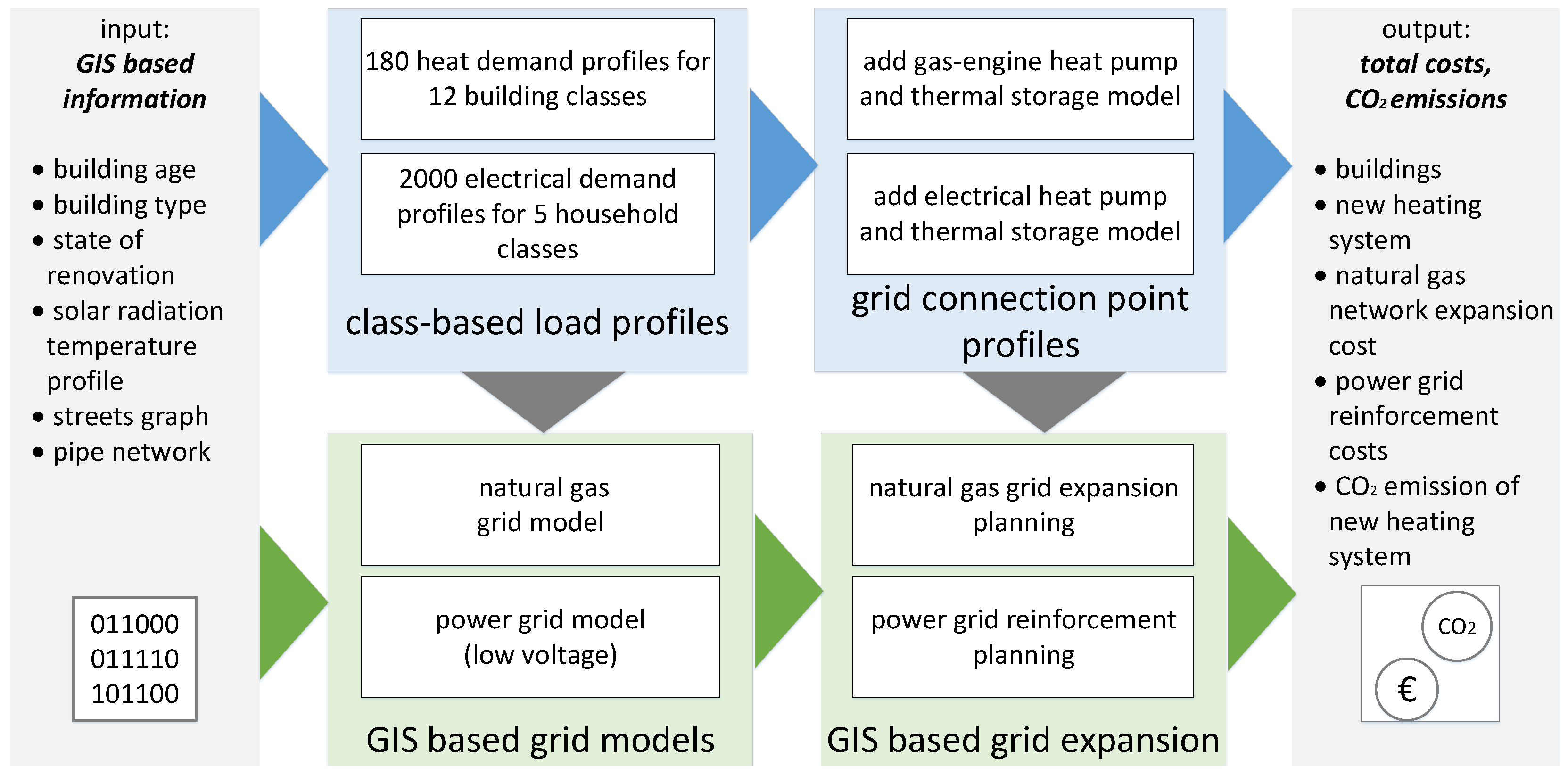
Figure 1. GIS-based approach for evaluating the total costs for an overall future infrastructure plan.
Energies 13 04052 g001
Figure 2. The region of the investigated town Schutterwald. Each colored square depicts a household. The color code describes the construction year class of each building (see legend in the right upper corner and, in the right lower corner, the inset for distribution of the number of houses for each period). Classification of periods based on [54].
Energies 13 04052 g002
Figure 3. Share of refurbished single-family and two-family homes of German stock of buildings in 2009 per construction year class, adapted from [55]. Class A and B were not differentiated in the reference. As no data for classes K and L were given in the reference, equal distributions to class J were assumed.
Energies 13 04052 g003
Figure 4. Synthetic electrical distribution grid of Schutterwald derived from open-source data. Each color represents a galvanically connected low voltage grid (grid group) that belongs to one transformer/external grid connection (squares). Due to the status of the switches, the different grid groups are not galvanically connected on the low voltage side.
Energies 13 04052 g004
Figure 5. Assumed connection costs for houses based on their linear distance to the natural gas grid and the specific costs given in Table 6.
Energies 13 04052 g005
Figure 6. Costs for heat generation for sample buildings of two construction year classes and three energetic insulation variants. Average of five simulated household types.
Energies 13 04052 g006
Figure 7. Calculated annual costs (depreciation, energy consumption, maintenance and interests) and emissions of different heating options for single-family homes (construction year period 1958 to 1968 and 2016 onwards). Average of five simulated household types. Underlying numbers can be found in Table A4 and Table A5. For electric heat pumps (eHPs), the emissions are given for different years (i.e., decreasing carbon intensity of electricity generation; see Table 5). Costs for energy and heating systems were assumed to stay constant for all years. Possible emission changes for gas that may come from changing gas mix are neglected.
Energies 13 04052 g007
Figure 8. Resulting building stock and assigned heat pumps (example, for the seed “0”; variant 1/2/3 = no/moderate/advanced energetic refurbishment). (a) Derived distribution of total housing stock in the town per construction year class and energy variant. (b) Share of selected buildings to be equipped with a heat pump. Scenario with 164 heat pumps. (c) Share of selected buildings to be equipped with a heat pump. Scenario with 247 heat pumps.
Energies 13 04052 g008
Figure 9. Sensitivity of overall cost for heat pumps in the cases in year 2030/164 heat pumps. Averages of all 20 seeds.
Energies 13 04052 g009
Figure 10. Synthetic low voltage grid of the town with 247 electric heat pumps (case 1—electric, for the seed “15”). Line overloads and bus voltages at time step with lowest bus voltage, prior to sectioning point optimization and grid extension.
Energies 13 04052 g010
Figure 11. Synthetic low voltage grid of the town with 171 geHPs and 76 eHPs (case 3—mixed). Line overloads and bus voltages at time step with the lowest bus voltage, prior to sectioning point optimization and grid extension. geHPs are not represented in the figure.
Energies 13 04052 g011
Figure 12. Box plots (n = 20) of calculated required grid investments for 164 and 247 deployed heat pumps (left) and emissions caused by deployed heat pumps in 2030 and 2050 (right). See also Table A7 and Table A8.
Energies 13 04052 g012
Figure 13. Average annualized costs (grid investment, heat pump investment, and operation) and annual emissions in 2030 and 2050 by heat pumps for cases 1—electric, 2—natural gas, and 3—mixed respectively.
Energies 13 04052 g013
Figure 14. Annual costs in 1000 euros/year for heat supply of 247 houses with heat pumps and connected required grid investments (annualized). Average of 20 seeds for each case.
Energies 13 04052 g014
Table 1. Different construction year classes for Germany as defined in [59].
NameYears
A1859 and earlier
B1860–1918
C1919–1948
D1949–1957
E1958–1968
F1969–1978
G1979–1983
H1984–1994
I1995–2001
J2002–2009
K2010–2015
L2016 and later
Table 2. Shares of different household types in the investigated municipality, based on [61] (summarized).
Household TypeCodeNumberShare
single, retiredSRa1726%
single, employedSOa53718%
couple, employed, 0 childrenPOa103035%
couple, employed, 1 childP1a52018%
couple, employed, 2 children or more *P2a68623%
* Other, bigger households were assigned to household type P2a, too.
Table 3. Assumed price parameters for heat generators [69].
Heat GeneratorInvestmentsMaintenance CostsDepreciation Period
ab[% of Investment/Year]
gas condensing boiler61 EUR/kW4794 EUR3.020 years
gas engine heat pump163 EUR/kW14797 EUR4.520 years
electric air water heat pump488 EUR/kW7461 EUR2.520 years
supplementary heating coil100 EUR/kW0 EUR0.020 years
hot water storage tank1120 EUR/m 3 806 EUR0.020 years
Table 4. Prices for energy usage (all prices including VAT).
Energy CarrierTariffVariable [EUR/kWh]+ Fix [EUR/Year]Ref.
electricitystandard0.28396.39[75]
heat pump tariff, 3 × 2 h blocking time0.231 (high load time)
0.196 (low load time)
71.40[75]
natural gasstandard (18–50 MWh/year)0.058122.40[76]
Table 5. Emission factors (scope 1 and 2).
Energy CarrierScopeEmission FactorReference
electricity (2017, domestic cons.)2537 g CO 2 - eq /kWh[73]
electricity (scenario 2030)2217 g CO 2 - eq /kWhcalculated based on [77]
electricity (scenario 2050)266 g CO 2 - eq /kWhcalculated based on [77]
natural gas1202 g CO 2 - eq /kWh[78]
Table 7. Exemplary simulation results from pandapower (for the seed “15”): load at worst time step (occurrence of lowest bus voltage) and lowest bus voltage and maximum line loading before and after sectioning point optimization (SPO) and after automated grid reinforcement planning (with cost-optimal cable reinforcement and parallel lines applied).
Case 1Case 3
number of heat pumps164247164 (47 eHP)247 (76 eHP)
total load at worst time step [MW]3.2973.5562.5952.687
load caused by eHP [MW]0.8391.7870.2250.317
lowest bus voltage [p.u.]before SPO0.8320.7960.8470.833
after SPO0.8950.8630.9080.896
after grid reinforcement0.9010.9090.9190.900
highest line loading [%]before SPO99.1133.479.190.3
after SPO92.4123.473.984.1
after grid reinforcement58.859.2759.359.8