Transient CFD Simulation on Dynamic Characteristics of Annular Seal under Large Eccentricities and Disturbances

 , , and
Abstract
:1. Introduction
2. Numerical Methods
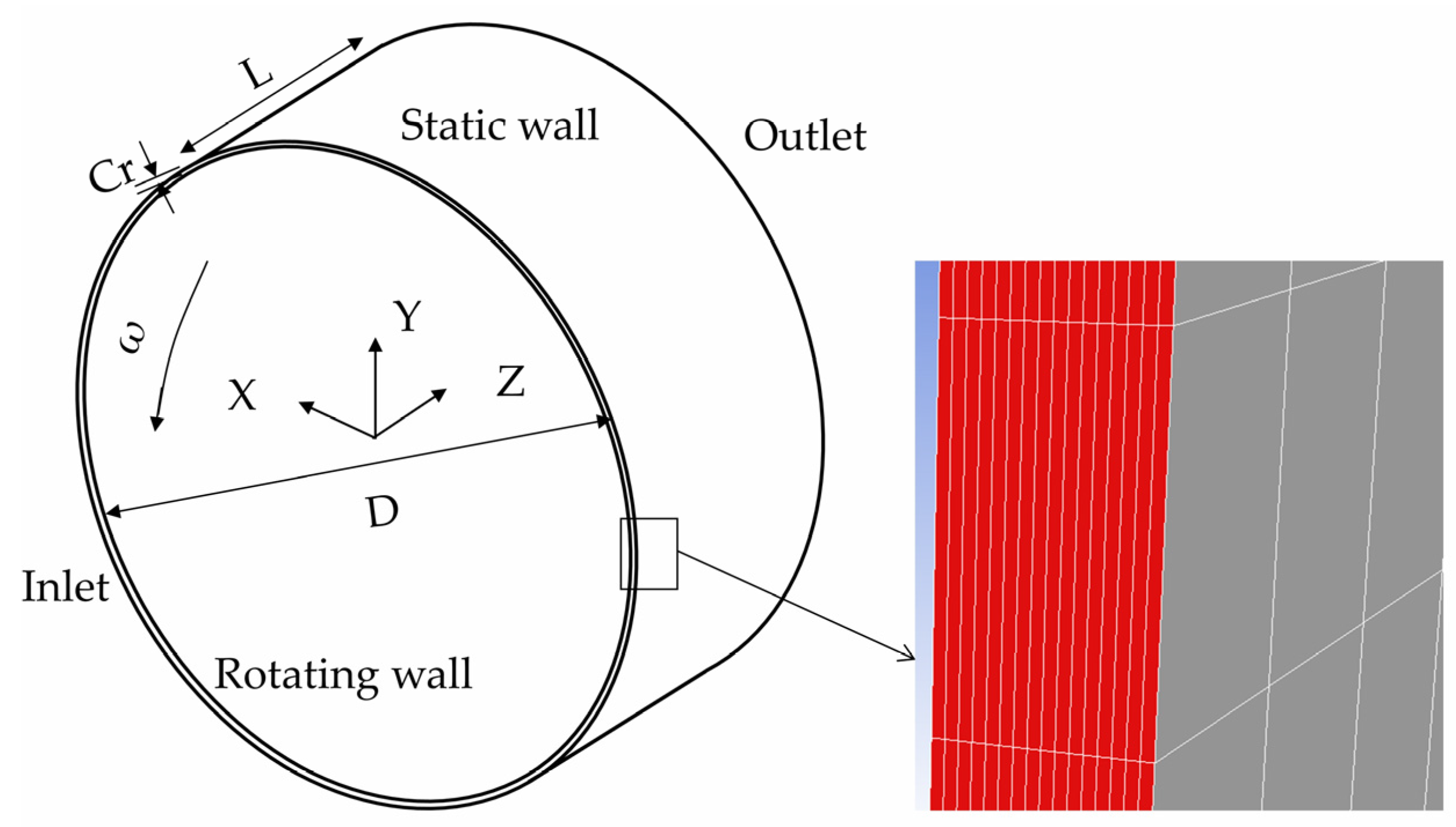
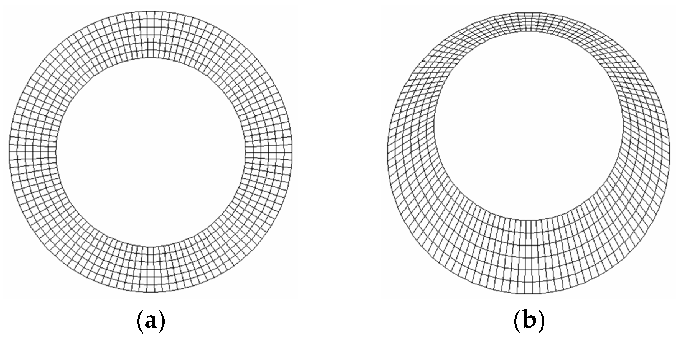
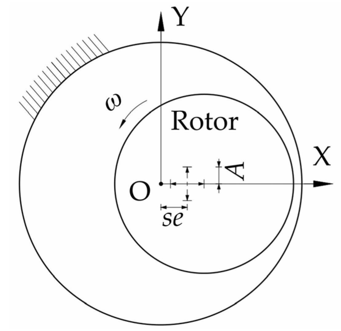
2.1. Geometry Model and Grid
2.2. 3D Transient Solutions
2.3. Computing Static and Dynamic Characteristics of Eccentric Annular Seals
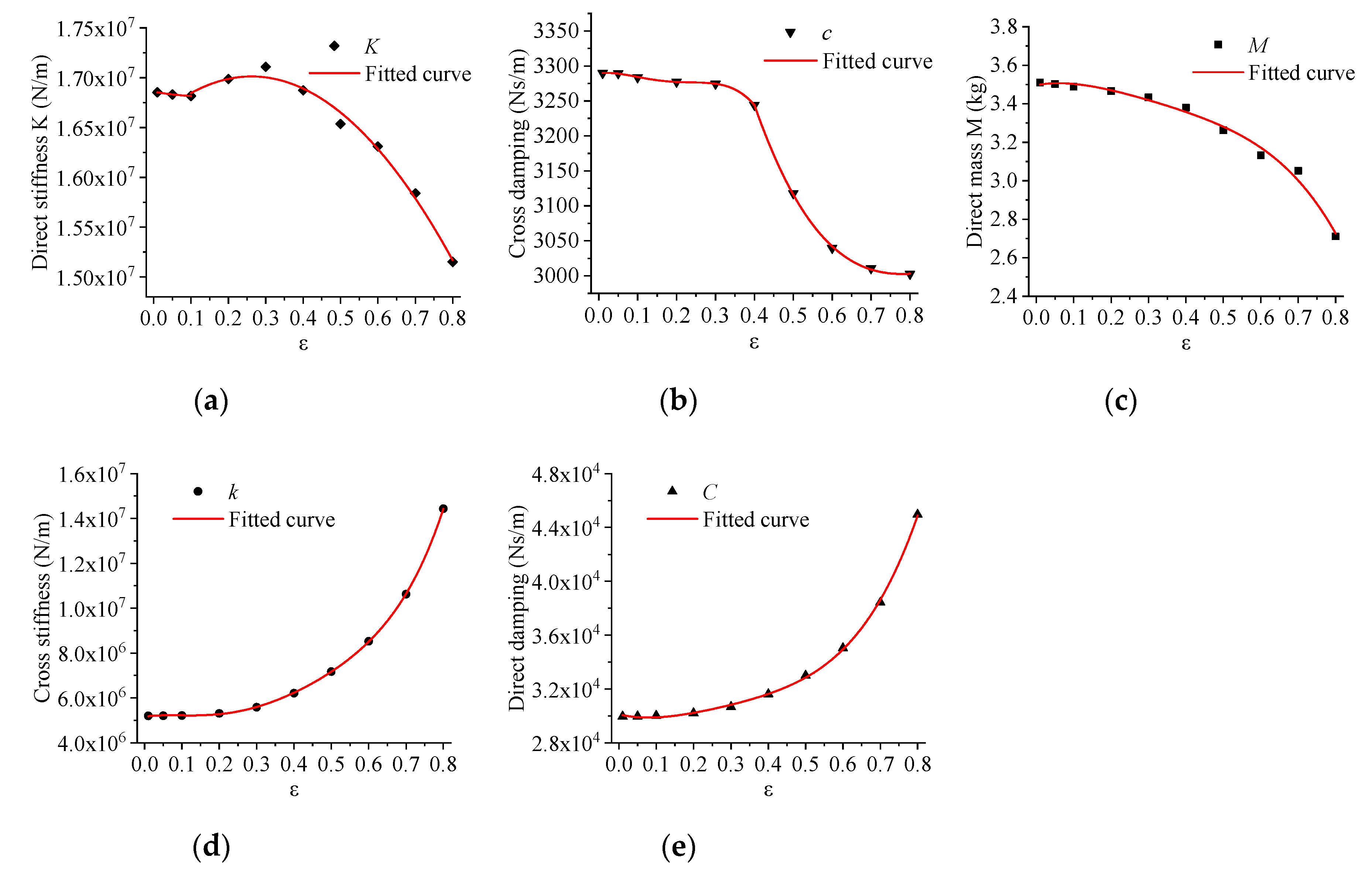
2.4. Fitting Nonlinear Dynamic Model
3. Results and Discussions
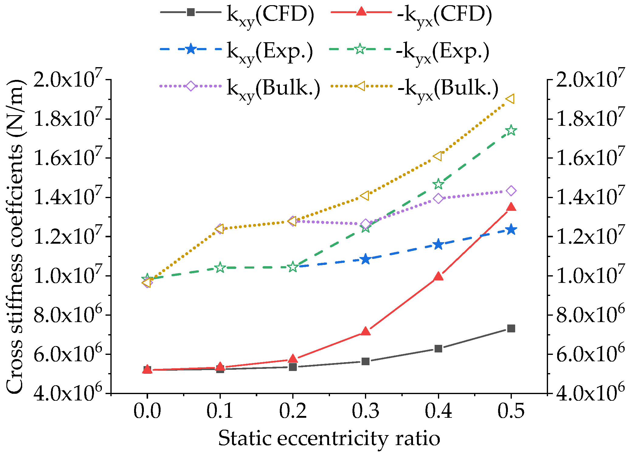
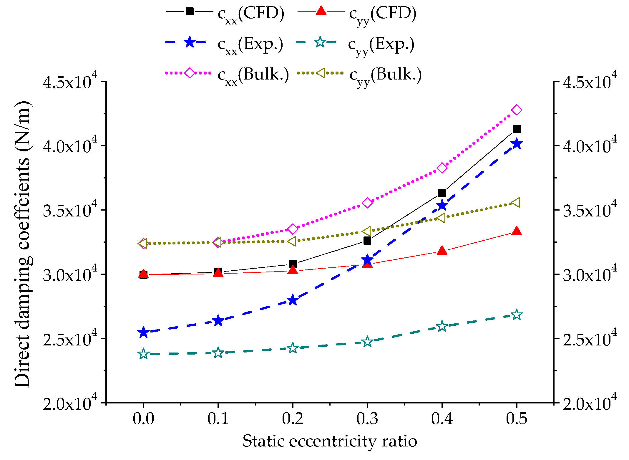
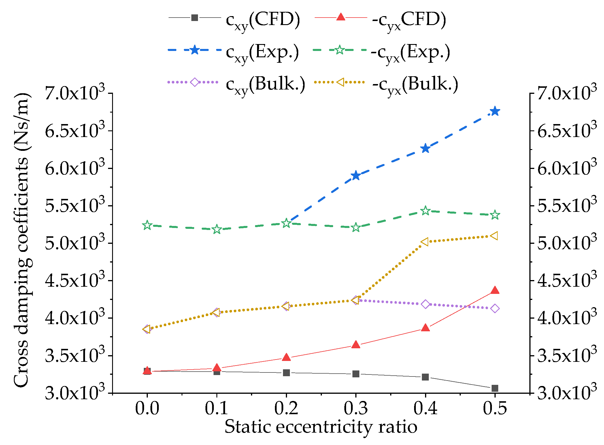
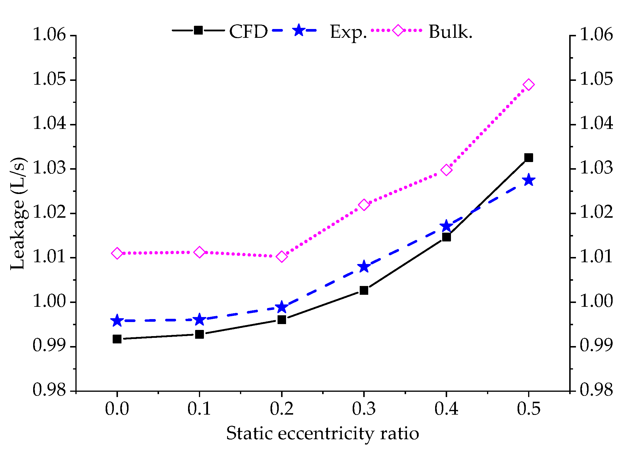
3.1. Dynamic Characteristics of Different Static Eccentric Seals and Comparisons
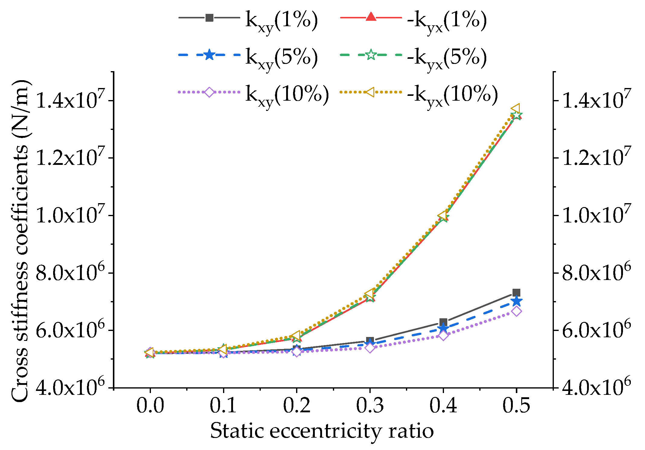
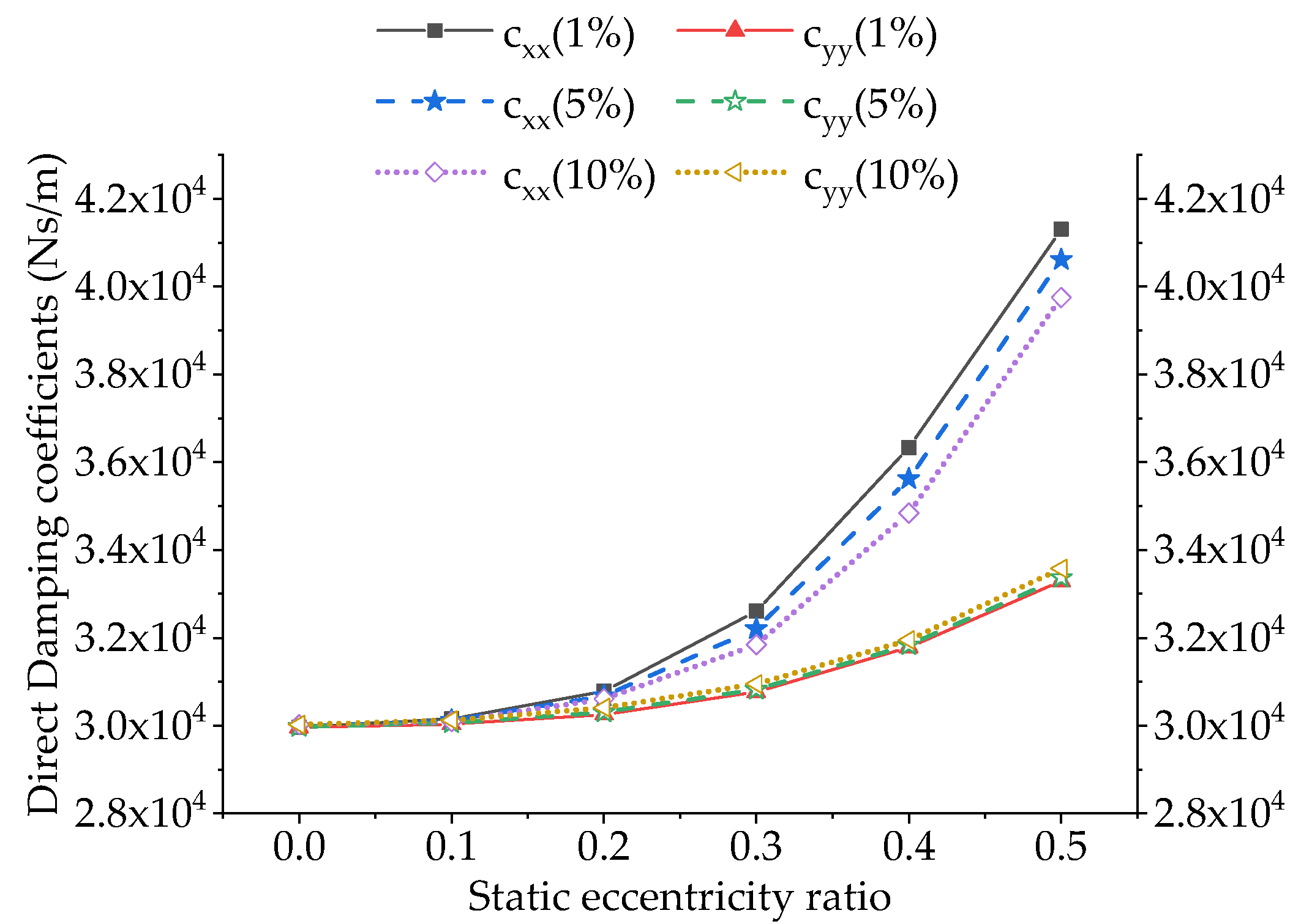
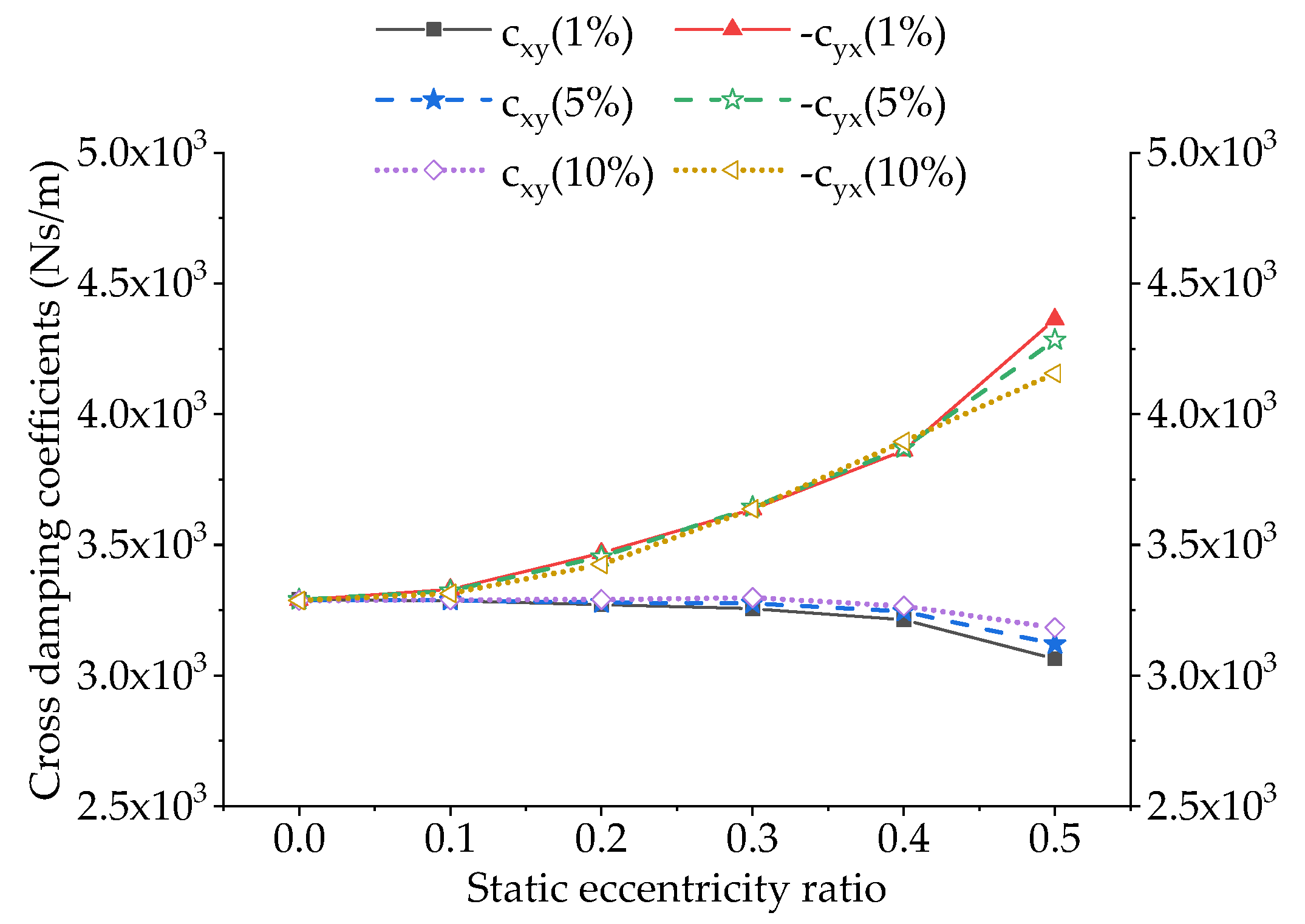
3.2. Effects of Disturbance Amplitude on Force Coefficients of Eccentric Annular Seal
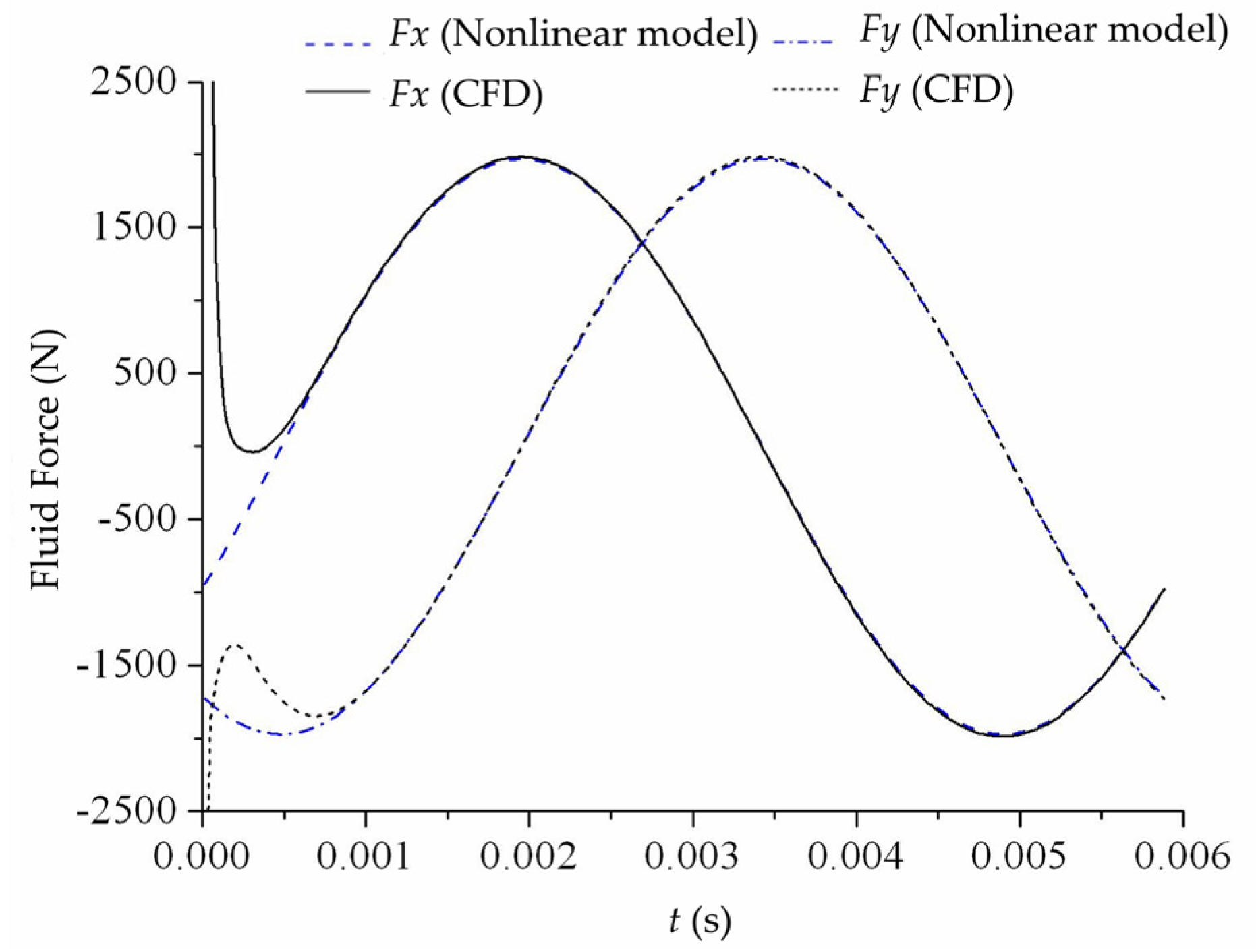
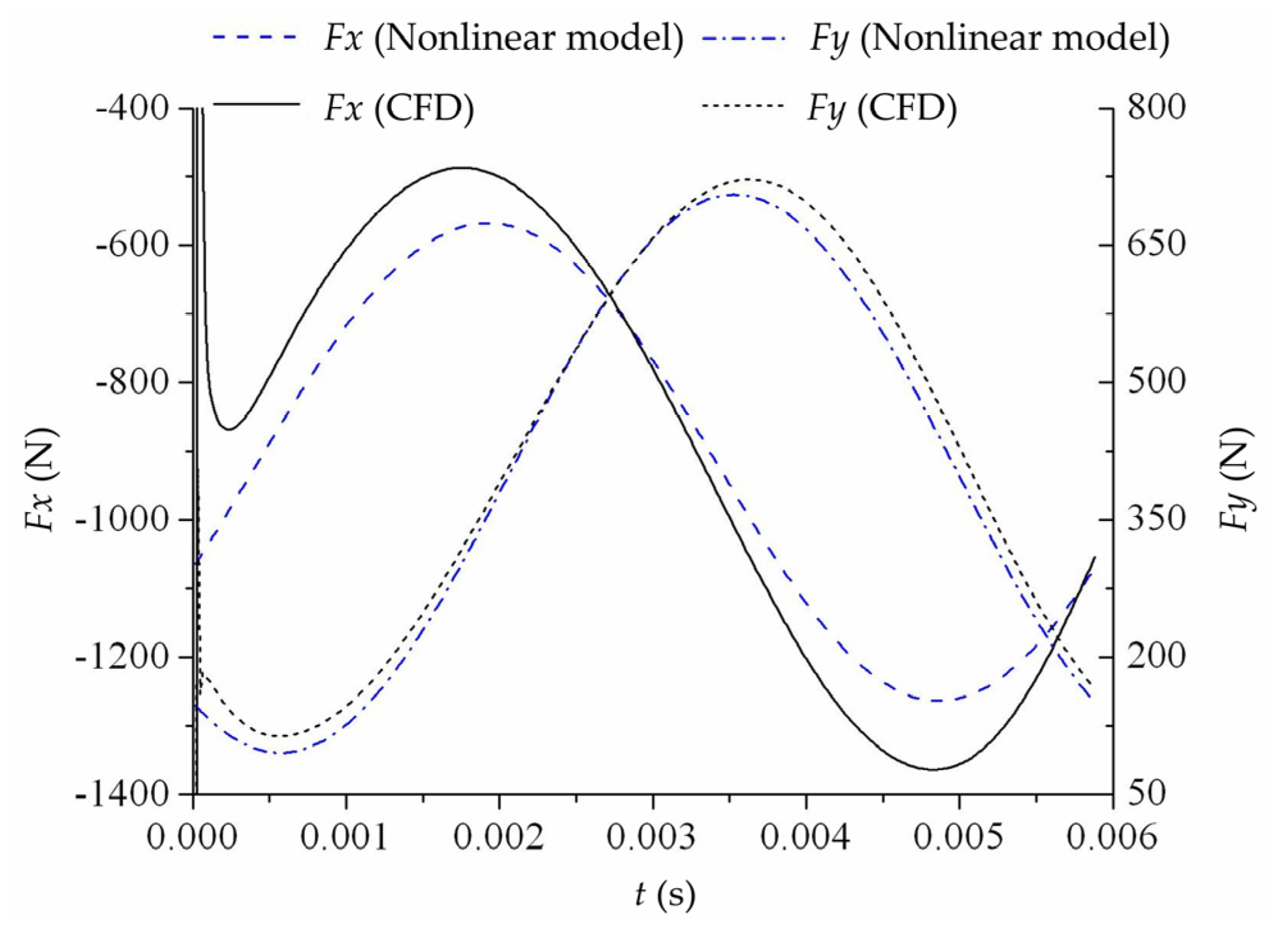
3.3. Nonlinear Dynamic Model
4. Fluid Excitations under Large Disturbances
4.1. Constant-Speed Circular Whirl Around Seal Center
4.2. Constant-Speed Circular Whirl Around Static Position
4.3. 1D Harmonic Shaking Motions
4.4. Quasi-Circular (Spiral) Whirl
5. Conclusions
Author Contributions
Funding
Conflicts of Interest
Nomenclature
| C: c | Direct and cross damping coefficients of concentric annular seal (N·s/m) |
| cxx, cyy, cxy, cyx | Damping coefficients of eccentric annular seal (N·s/m) |
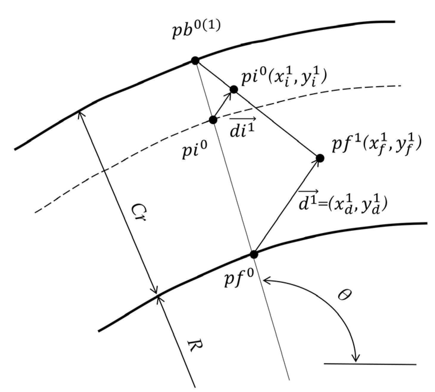
| Cr | Seal clearance (mm) |
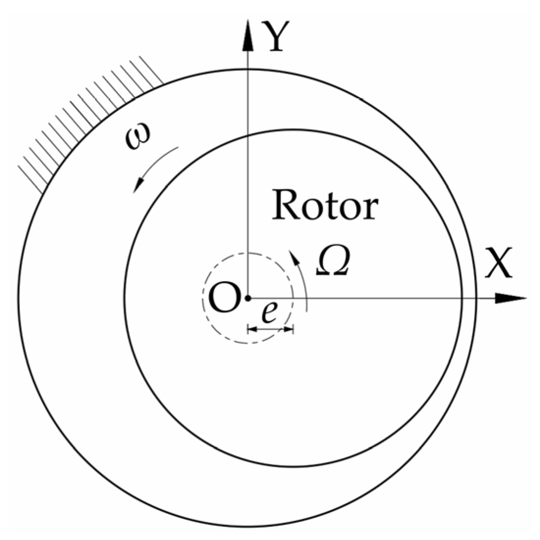
| e | Rotor eccentricity or whirl radius (mm] |
| f | Eccentricity speed of the rotor |
| Fx, Fy | Fluid forces in X and Y directions (N) |
| Fx0, Fy0 | Fluid forces at equilibrium position (N) |
| ΔFx, ΔFy | The increments of fluid forces relative to Fx0 and Fy0 (N) |
| K, k | Direct and cross stiffness coefficients of concentric seal (N/m) |
| kxx, kyy, kxy, kyx | Stiffness coefficients of eccentric annular seal (N/m) |
| M | Direct mass coefficient of concentric annular seal (kg) |
| mxx, myy | Direct mass coefficients of eccentric annular seal (kg) |
| ra | Ratio of the distance between the nodes in the clearance domain and the outer static wall to the clearance |
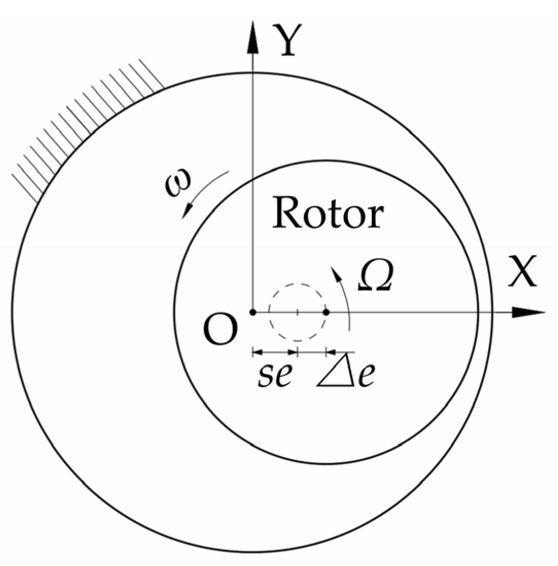
| se | Rotor static eccentricity (mm) |
| se/Cr | Static eccentricity ratio |
| t | Time (s) |
| x, y | The displacements of rotor center (mm) |
| Δx, Δy | Rotor displacements relative to equilibrium position (mm) |
| Δe | Rotor dynamic eccentricity (mm) |
| ε | Eccentricity ratio (e/Cr) |
| ω | Rotating speed of the rotor (rpm) |
| Ω | Whirling speed of the rotor (rpm) |
References
- Du, Q.; Zhang, D. Numerical investigation on flow characteristics and aerodynamic performance of a 1.5-stage SCO2 axial-inflow turbine with labyrinth seals. Appl. Sci. 2020, 10, 373. [Google Scholar] [CrossRef] [Green Version]
- Wang, X.; Liu, M.; Kao-Walter, S.; Hu, X. Numerical Evaluation of Rotordynamic Coefficients for Compliant Foil Gas Seal. Appl. Sci. 2020, 10, 3828. [Google Scholar] [CrossRef]
- Xia, P.; Chen, H.; Liu, Z.; Ma, W.; Yang, B. Analysis of Whirling Motion for the dynamic System of Floating Ring Seal and Rotor. Proc. Inst. Mech. Eng. Part J J. Eng. Tribol. 2019, 233, 1–15. [Google Scholar] [CrossRef]
- Awad, H.; Parrondo, J.; González, V. Vibrations in Leaking Spherical Valves with Annular Seal. Proceedings 2018, 2, 1444. [Google Scholar] [CrossRef] [Green Version]
- Zhai, L.; Wu, G.; Wei, X.; Qin, D.; Wang, L. Theoretical and Experimental Analysis for Leakage Rate and Dynamic Characteristics of Herringbone-Grooved Liquid Seals. Proc. Inst. Mech. Eng. Part J J. Eng. Tribol. 2015, 229, 849–860. [Google Scholar] [CrossRef]
- Ikemoto, A.; Inoue, T.; Sakamoto, K.; Uchiumi, M. Nonlinear Analysis of Rotordynamic Fluid Forces in the Annular Plain Seal by Using Extended Perturbation Analysis of the Bulk-Flow Theory (Influence of Whirling Amplitude in the Case with Concentric Circular Whirl). J. Tribol. 2018, 140, 1–15. [Google Scholar] [CrossRef]
- Gao, R.; Kirk, G. CFD Study on Stepped and Drum Balance Labyrinth Seal. Tribol. Trans. 2013, 56, 663–671. [Google Scholar] [CrossRef]
- Untaroiu, A.; Hayrapetian, V.; Untaroiu, C.D.; Wood, H.G.; Schiavello, B.; McGuire, J. On the Dynamic Properties of Pump Liquid Seals. J. Fluids Eng. 2013, 135, 051104. [Google Scholar] [CrossRef]
- Li, F.; Cui, B.; Zhai, L. Research on Rotordynamic Characteristics of Pump Annular Seals Based on a New Transient CFD Method. Processes 2020, 8, 227. [Google Scholar] [CrossRef] [Green Version]
- Childs, D.W.; Arthur, S.P. Static Destabilizing Behavior for Gas Annular Seals at High Eccentricity Ratios. In Proceedings of the ASME Turbo Expo 2013: Turbine Technical Conference and Exposition, San Antonio, TX, USA, 3–7 June 2013; Volume 7A, pp. 1–7. [Google Scholar]
- Nelson, C.C.; Nguyen, D.T. Analysis of Eccentric Annular Incompressible Seals: Part 1—A New Solution Using Fast Fourier Transforms for Determining Hydrodynamic Force. J. Tribol. 1988, 110, 354. [Google Scholar] [CrossRef]
- Andres, L.A.S. Analysis of Variable Fluid Properties, Turbulent Annular Seals. J. Tribol. 1991, 113, 694–702. [Google Scholar] [CrossRef]
- Arghir, M.; Frene, J. A Bulk-Flow Analysis of Static and Dynamic Characteristics of Eccentric Circumferentially-Grooved Liquid Annular Seals. J. Tribol. 2004, 126, 316–325. [Google Scholar] [CrossRef]
- Venkataraman, B.; Palazzolo, A.B. Thermohydrodynamic Analysis of Eccentric Annular Seals Using Cubic Spline Interpolations©. Tribol. Trans. 1997, 40, 183–194. [Google Scholar] [CrossRef]
- Athavale, M.M.; Hendricks, R.C. A Small Perturbation CFD Method for Calculation of Seal Rotordynamic Coefficients. Int. J. Rotating Mach. 1996, 2, 167–177. [Google Scholar] [CrossRef] [Green Version]
- Wu, D.; Jiang, X.; Li, S.; Wang, L. A New Transient CFD Method for Determining the Dynamic Coefficients of Liquid Annular Seals. J. Mech. Sci. Technol. 2016, 30, 3477–3486. [Google Scholar] [CrossRef]
- Andres, L.S.; Jeung, S.H. Orbit-Model Force Coefficients for Fluid Film Bearings: A Step beyond Linearization. J. Eng. Gas Turbines Power 2016, 138, 1–11. [Google Scholar]
- Muszynska, A.; Bently, D.E. Frequency-swept Rotating Input Perturbation Techniques and Identification of the Fluid Force Models in Rotor/Bearing/Seal Systems and Fluid Handling Machines. J. Sound Vib. 1990, 143, 103–124. [Google Scholar] [CrossRef]
- Li, Z.G.; Chen, Y.S. Research on 1:2 Subharmonic Resonance and Bifurcation of Nonlinear Rotor-Seal System. Appl. Math. Mech. (English Ed.) 2012, 33, 499–510. [Google Scholar] [CrossRef]
- He, H.J.; Jing, J.P. Research into the Dynamic Coefficient of the Rotor-Seal System for Teeth-on-Stator and Teeth-on-Rotor Based on an Improved Nonlinear Seal Force Model. J. Vib. Control 2014, 20, 2288–2299. [Google Scholar] [CrossRef]
- Marquette, O.R.; Childs, D.W.; San Andres, L. Eccentricity Effects on the Rotordynamic Coefficients of Plain Annular Seals: Theory Versus Experiment. J. Tribol. 1997, 119, 443. [Google Scholar] [CrossRef]
- Childs, D.W.; Arthur, S.; Mehta, N.J. The Impact of Hole Depth on the Rotordynamic and Leakage Characteristics of Hole-Pattern-Stator Gas Annular Seals. J. Eng. Gas Turbines Power 2013, 136, 042501. [Google Scholar] [CrossRef]
- Muszynska, A. Whirl and Whip—Rotor/Bearing Stability Problems. J. Sound Vib. 1986, 110, 443–462. [Google Scholar] [CrossRef] [Green Version]
- Muszynska, A. Improvements in Lightly Loaded Rotor/Bearing and Rotor/Seal Models. J. Vib. Acoust. Stress. Reliab. Des. 1988, 110, 129–136. [Google Scholar] [CrossRef]
- Li, Q.; Liu, S.; Pan, X.; Zheng, S. A New Method for Studying the 3D Transient Flow of Misaligned Journal Bearings in Flexible Rotor-Bearing Systems. J. Zhejiang Univ. Sci. A 2012, 13, 293–310. [Google Scholar] [CrossRef]
- Childs, D.W. Dynamic Analysis of Turbulent Annular Seals Based On Hirs’ Lubrication Equation. J. Lubr. Technol. 1983, 105, 429–436. [Google Scholar] [CrossRef]
- Ha, T.W.; Choe, B.S. Numerical Simulation of Rotordynamic Coefficients for Eccentric Annular-Type-Plain-Pump Seal Using CFD Analysis. J. Mech. Sci. Technol. 2012, 26, 1043–1048. [Google Scholar] [CrossRef]
- Wu, D.; Jiang, X.K.; Chu, N.; Wu, P.; Wang, L.Q. Numerical Simulation on Rotordynamic Characteristics of Annular Seal under Uniform and Non-Uniform Flows. J. Cent. South Univ. 2017, 24, 1889–1897. [Google Scholar] [CrossRef]
- Yan, X.; Li, J.; Feng, Z. Investigations on the Rotordynamic Characteristics of a Hole-Pattern Seal Using Transient CFD and Periodic Circular Orbit Model. J. Vib. Acoust. 2011, 133, 041007. [Google Scholar] [CrossRef]


| Main Parameters | Symbols | Values | Units |
|---|---|---|---|
| seal length | L | 34.93 | mm |
| seal diameter | D | 76.29 | mm |
| seal clearance | Cr | 0.11 | mm |
| rotating speed | ω | rpm | |
| pressure difference | ∆P | 5.52 | MPa |
| length-diameter ratio | L/D | 0.46 |
| Name | Grid Density | Fr/N | Relative Error 1 | Ft/N | Relative Error 1 |
|---|---|---|---|---|---|
| Grid 1 | 16 × 204 × 1448 | 1331.43 | 2.53% | 1278.62 | 1.52% |
| Grid 2 | 16 × 254 × 1448 | 1358.79 | 0.52% | 1289.26 | 0.70% |
| Grid 3 | 16 × 318×1448 | 1365.92 | - | 1298.33 | - |
| Grid 4 | 16 × 397 × 1448 | 1367.51 | −0.12% | 1299.54 | −0.09% |
| Grid 5 | 16 × 477 × 1448 | 1367.86 | −0.14% | 1300.15 | −0.14% |
| Grid 6 | 16 × 318 × 926 | 1344.51 | 1.57% | 1276.36 | 1.69% |
| Grid 7 | 16 × 318 × 1158 | 1360.28 | 0.41% | 1290.79 | 0.58% |
| Grid 8 | 16 × 318 × 1810 | 1366.09 | −0.01% | 1298.65 | −0.02% |
| Grid 9 | 16 × 318 × 2170 | 1365.82 | 0.01% | 1298.93 | −0.05% |
© 2020 by the authors. Licensee MDPI, Basel, Switzerland. This article is an open access article distributed under the terms and conditions of the Creative Commons Attribution (CC BY) license (http://creativecommons.org/licenses/by/4.0/).
Share and Cite
Zhang, K.; Jiang, X.; Li, S.; Huang, B.; Yang, S.; Wu, P.; Wu, D. Transient CFD Simulation on Dynamic Characteristics of Annular Seal under Large Eccentricities and Disturbances. Energies 2020, 13, 4056. https://doi.org/10.3390/en13164056
Zhang K, Jiang X, Li S, Huang B, Yang S, Wu P, Wu D. Transient CFD Simulation on Dynamic Characteristics of Annular Seal under Large Eccentricities and Disturbances. Energies. 2020; 13(16):4056. https://doi.org/10.3390/en13164056
Chicago/Turabian StyleZhang, Kai, Xinkuo Jiang, Shiyang Li, Bin Huang, Shuai Yang, Peng Wu, and Dazhuan Wu. 2020. "Transient CFD Simulation on Dynamic Characteristics of Annular Seal under Large Eccentricities and Disturbances" Energies 13, no. 16: 4056. https://doi.org/10.3390/en13164056