Article

Insights into the Aeroacoustic Noise Generation for Vertical Axis Turbines in Close Proximity

by
Manuel Viqueira-Moreira
1 and
Esteban Ferrer
2,*
1
ETSIAE-UPM (School of Aeronautics), Universidad Politécnica de Madrid, Plaza de Cardenal Cisneros 3, 28040 Madrid, Spain
2
Center for Computational Simulation (CCS), Universidad Politécnica de Madrid, Campus de Montegancedo, Boadilla del Monte, 28660 Madrid, Spain
*
Author to whom correspondence should be addressed.
Energies 2020, 13(16), 4148; https://doi.org/10.3390/en13164148
Submission received: 18 June 2020 / Revised: 7 August 2020 / Accepted: 10 August 2020 / Published: 11 August 2020
(This article belongs to the Special Issue Machine-Learning Methods for Complex Flows)

Abstract

:
We present Large Eddy Simulations and aeroacoustic spectra for three configurations of increasing flow complexity: an isolated NACA0012 airfoil, an isolated rotating vertical axis wind turbine composed of three rotating airfoils and a farm of four vertical axis turbines (with identical characteristics as the isolated turbine), which are located in close proximity. The aeroacoustic signatures of the simulated airfoil and the isolated turbine are validated using published numerical and experimental data. We provide theoretical estimates to predict tonal frequencies, which are used to identify the main physical mechanisms responsible for the tonal signature and for each configuration and enable the categorisation of the main tonal aeroacoustic sources of vertical axis turbines operating in close proximity. Namely, we identify wake, vortex, blade passing and boundary layer phenomena and provide estimates for the associated tonal frequencies, which are validated with simulations. In the farm, we observe non-linear interactions and enhanced mixing that decreases tonal frequencies in favour of larger broadband amplitudes at low frequencies. Comparing the spectrum with that of the isolated turbine, only the blade passing frequency and the boundary layer tones can be clearly identified. Variations in acoustic amplitudes, tonal frequencies and sound directivities suggest that a linear combination of sources from isolated turbines is not enough to characterise the aeroacoustic footprint of vertical axiswind turbines located in close proximity, and that farms need to be considered and studied as different entities.

Graphical Abstract

1. Introduction

Vertical axis wind turbines (VAWTs) for power generation [1], also known as H-rotors or Darrieus turbines, present complex unsteady flow phenomena and associated aeroacoustics. To date, VAWTs have had limited use within the wind energy sector, where the three bladed horizontal axis flow turbine has been widely adopted. However, it is thought that VAWT configurations may be advantageous for new emergent markets such as urban environments (e.g., turbines on building roofs).
VAWT have the advantage of not requiring orientation since they rotate independently of the stream direction and hence researchers argue that this technology is more suitable for urban environment, as it would minimise maintenance costs through reduced control systems (e.g., yaw mechanism). Additionally, H-rotors can be less harmful for birds and bats, since the blades move at a slower pace [2]. Regarding noise, VAWTs usually have a tip speed, which is half the tip speed of horizontal axis wind turbines, and therefore are more silent [2] and can be better suited for urban environments. A deeper review of the arguments in favour and against VAWTs and its use in urban environments can be found in [2,3].
Recent studies e.g., [4,5], suggest a faster wake recovery for VAWTs that for horizontal turbines, making these more suitable for farms. Additionally, VAWTs placed side by side (sometimes called double rotor) extract more power [6,7,8] due to the local flow redirection enhancing the generation of torque. Similarly, clustering VAWTs in close proximity (distances between turbine centres of two to five diameters) increases power extraction [9,10,11] These studies highlight the potential of designing farms with VAWTs placed in close proximity for their use in urban environments, e.g., on building roofs [12]. Motivated by these recent findings, in this text we explore the physics behind the aeroacoustics of VAWTs in close proximity.
Turbine noise may be categorised in two types: mechanical (typically low frequencies of 20–2 kHz in large wind turbines) and flow-acoustic noise (complex broadband/tonal spectrum 20–10 kHz). The first type has a defined tonal character and is produced by the mechanical components as the gearbox and bearings (and/or generator or cooling systems) and may be controlled by appropriate insulation. The second type of noise is more complex and is caused by the interaction of the blades moving through the air and is generally called aeroacoustic. Predicting and controlling the latter is possible through an accurate understanding of the interactions of unsteady flows through the rotor, around the rotating blades and developed wakes.
Turbine acoustics [13,14] is a complex process and various types of acoustic sources have been identified in the past. The most important are briefly described here: Steady loading relates to the distribution of forces along the blade leading to broadband noise. Unsteady loading relates to the incoming sheared and turbulent atmospheric flow and is associated to low frequency noise. Blade or airfoil self-noise encompasses various high frequency phenomena that relate to the boundary layer and eddies generated as the air passes the blades. Blade noise has both broadband and tonal character and is mainly felt downstream of the turbine. Unsteady flow phenomena are responsible of this type of noise, which includes noise generated by blunt trailing edges, turbulent boundary layers, shed vortices, among others. These highly unsteady effects can be found in both horizontal and vertical axis turbines, although the latter type is more prone to generate unsteady phenomena. In this category, other complex physics such flow detachment, blade tip vortices [15] and vortex-blade interactions [16] can be included. Wake development is another factor that can influence the acoustics of VAWTs.
The modelling of VAWT wakes using numerical techniques has been recently addressed in [17] and by the second author of this text in [18,19,20]. A recent review by Du et al. [21] covers these different aspects. Whilst tip vortices or vortex-blade interactions have a tonal character, stalled flows and wakes produce broadband noise. In this work, we include an identification of the physical phenomena responsible for the acoustics of isolated turbines and turbines in close proximity, and is the first step towards understanding noise generation to design silent VAWT farms in the future.
Experiments and simulations have been used in the past to understand the aerodynamics of VAWT, see [21] for a recent review. However, limited work exists about VAWT aeroacoustics and, to the authors knowledge, none regarding farms of vertical axis turbines. Meaningful experimental studies include [22,23], which provide the experimental data used in this text. Pearson’s PhD thesis [24] provides a wide overview of VAWT noise and includes interesting experimental results. The thesis concludes that peaks at 1–2 kHz can be expected and are attributed to boundary layer tonal noise. We also observe these tones in this manuscript. Much of the previous work has focussed on dynamic stall effects, which are often observed in VAWT, but are not present for our selected conditions. Indeed, the selected experiments [22] are obtained with large tip speed ratios that prevent the blades from undergoing dynamic stall. This facilitates to some extend our analysis and reduces the noise sources in the upstream half of the rotor. Additional experimental work includes [25,26,27].
Recent numerical studies for the acoustics of VAWTs [28,29,30] used Large Eddy Simulation type turbulent models, for they enhanced performance in highly unsteady regimes. These works provided interesting insights into the effect of tip speed ratio and solidity on noise generation for isolated turbines. Unsteady Reynolds Averages Navier-Stokes simulations have also been used to propose silent VAWTs [31], to study silent airfoils for VAWTs [32] and to derive broadband noise models [33]. In this work we retain a Large Eddy Simulation approach.
In summary, the prediction of aero-acoustic noise is a remarkable subject due to the complexity of the flow features involved in the generation and propagation of sound. Here, we consider large eddy resolved numerical simulations, where the complex physics mentioned above are taken into account explicitly. Particular attention will be paid to the acoustic generation of the isolated VAWT and to the modification of the acoustics when locating turbines in close proximity. We include theoretical estimates for the various tonal frequencies expected in VAWT, which are used to analyse the obtained spectrum. We attempt to characterise the acoustic sources to enable a deeper understanding of the physics behind the acoustic generation in VAWT and groups of turbines in close proximity.
The contributions included in this text are summarised below:
  • We provide validation for Large Eddy Simulations of airfoils and VAWTs.
  • We propose physics-based theoretical estimates for tonal frequencies appearing in VAWTs.
  • We identify tonal frequencies in VAWT and group of four turbines in close proximity (or farm).
  • We analyse the spectra and directivities of the isolated VAWT and the farm of four VAWTs, and identify the main physical mechanisms of noise generation.
The remainder of the text is organised as follows: First, the numerical methodology presents flow parameters and meshes used in the study. Second, simulation results for an isolated airfoil, and isolated VAWT and a group of four VAWTs in close proximity are presented and include validation of the methodology and identification of the main tonal frequencies with the help of theoretical estimates. Finally, conclusions and an outlook are included.

2. Methodology

The numerical computation of aeroacoustics presents two distinct problems: noise generation (near field) and noise propagation (far field). Although direct computation of acoustics (near and far field are solved together) is possible to date only for small cases, the hybrid approach is generally preferred to lower the cost in large complex simulations. Acoustic analogies, e.g., [34,35,36] have enabled a certain degree of decoupling between the generation and propagation of noise. Following these analogies, equivalent acoustic sources can be extracted from the well resolved near field region. These can be subsequently modelled and injected into a new simulation to predict their propagation. The decoupling enables faster computations, since the near field that requires highly accurate flow computations can be performed separately from the acoustic propagation, see [13,37].
More precisely, in this work the near field needs accurate predictions of the unsteady pressure fluctuations using Large Eddy Simulations (LES). For turbines, this requires using rotating sliding meshes. In the far field, we use a Ffowcs Williams-Hawking (FWH) analogy for the propagation of noise up to the various microphones located far from the aeroacoustic generation region.

2.1. Solver Details

In this work we use ANSYS-Fluent (ANSYS Academic Research Mechanical, Release 18.1) to compute the generation and to propagate the acoustics to various microphone locations. As in [28,29], we select the LES turbulence model with Wall-Adapting Local Eddy-viscosity (WALE), to correct the wall asymptotic behaviour and we propagate noise using the FWH approach. Convective fluxes are discretised using a second order scheme and diffusive fluxes are approximated with a node-based gradient approach and central differencing. Inflow turbulence levels are kept to minimum values such that only the simulated geometry is responsible for the generation of turbulent flow structures. When simulating rotating VAWTs, rotating sliding meshes are used to enable the relative motion of the blades (embedded into a rotating mesh) with respect to a static outer mesh.

2.2. Configurations and Meshes

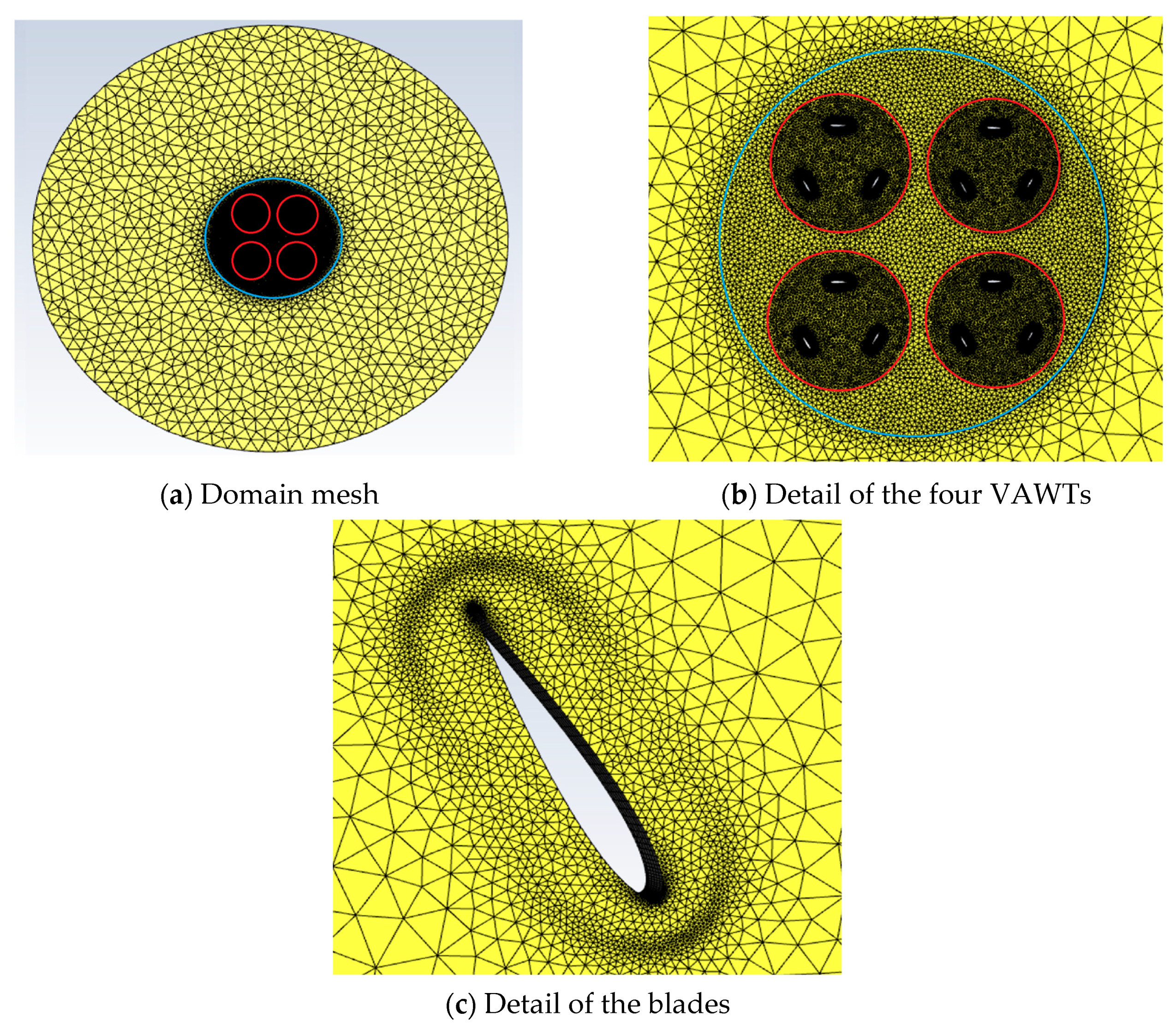
To simulate the isolated NACA0012 airfoil, we generate a mesh of C-grid type, whilst for the VAWT simulations we utilise O-type grids, as shown in Figure 1. To generate the mesh for the farm of four VAWT in close proximity, we embed four O-grids (one for each VAWT) within a larger circular region, as depicted in Figure 2. In the figures the blue circle indicates the Ffowcs Williams-Hawking surface, where acoustic source terms are computed.
Details for all simulated cases are summarised in the Table 1. All simulations are three-dimensional to enable 3D turbulent flow to develop. The out of plane domain lengths range from 10 to 40% of the chord length and is discretised using typically 20 mesh elements and periodic boundary conditions. This extension enables the development of 3D turbulence, whilst minimising the mesh size.
All simulations are run for a total time of 3 s (at least), which in the case of the VAWT and the group of turbines is equivalent to 40 wind turbine rotations). These long time series provide enough temporal information to perform accurate frequency analyses, even for low frequencies. We do not perform any filtering (in time or frequency) to the signals.

3. Numerical Simulations

This section describes and discusses the results obtained for the three selected configurations.

3.1. Aeroacoustic Sources for an Isolated NACA0012 Airfoil

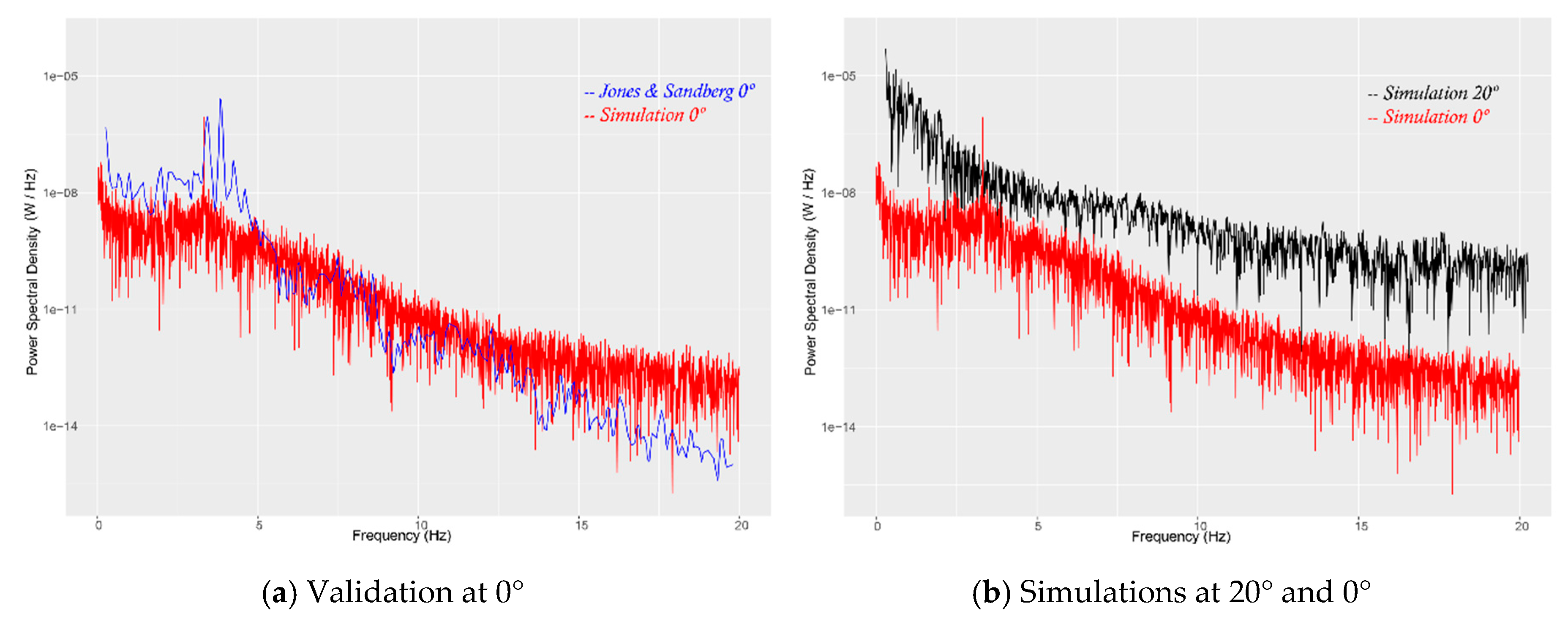
We simulate an isolated NACA0012 at 0° and 20°. We place a microphone at 0.5 m up the middle of the airfoil and compare our power spectral density spectrum, obtained using LES and FWH (Kirchhoff surface located at 0.1 m from the airfoil surface) to direct numerical simulation (DNS) results by Jones and Sandberg [38]. They reported tonal frequency ranging from 3.83 to 4.11 Hz, when varying the angle of attack from 0° to 2°, whilst the power spectral density (PSD) amplitudes decreased from 5.2 × 10 3 to 4.4 × 10 4 .
The PSD spectrum is compared to our results, in Figure 3a, for 0° angle of attack. We observe a tonal peak at the main shedding frequency ( 4 Hz), which is captured both by the DNS (blue curve) and our simulation (red curve). The amplitude of this tone is well captured, however, the DNS simulation shows a second peak above the main frequency ( 4.5 Hz), which is not captured by our simulation. In general, there is good agreement throughout the frequency range computed, with mild differences for high frequencies (>14 Hz), which are attributed to the lower spatial resolution of our LES simulation, when compared to the reference DNS. We note here that we have computed the same case using a unsteady RANS approach (with k-omega SST) to obtain a steady flow that resulted in unrealistic aeroacoustic (i.e., zero amplitude for all frequencies), which highlights the importance of selecting an appropriate turbulence model such as LES. A number of differences between our simulations and the DNS results [38] help explain the discrepancies observed in Figure 3a. Jones and Sandberg’s DNS results [38] are 2D and obtained using a compressible solver with Mach number 0.4, whilst our results are 3D and incompressible. Additionally, they used ensemble averaging with 50 percent overlap and Hanning windowing, yielding smooth curves, whilst we do not perform any treatment of the signal, which explains our noisy spectrum. Let us note that the mechanism controlling the tonal noise for the NACA0012 airfoil at 0° has been a topic of debate for some time, and for this reason we include a deeper discussion in Appendix A.
In Appendix B, we provide estimates for the time-space scaling of the main physical phenomena encountered in VAWT. These estimates can be used to predict the tonal frequencies, using Table A1, which can be calculated using the flow conditions detailed in Table 1. We can estimate the frequency associated to the boundary layer thickness f B L = 1 / τ B L = U λ ( Re b l a d e ) γ c , with γ = 1 / 5 for a turbulent boundary layer and with the tip speed ratio λ = 1 in this case (no rotation), we obtain f B L = 10 Hz. However, let us note that it was reported by Paterson et al. [39] that the shedding frequency for isolated airfoils can be associated to twice the boundary layer thickness. Therefore, the expected frequency is in fact f B L = 5 Hz, which agrees well with the value of 4 Hz reported in Figure 3. In Figure 3b, we include the PSD spectrum at 20°, the flow is now detached over the whole upper surface, resulting in broadband noise with higher amplitude for all frequencies. In our case, we do not observe any tonal peak at this angle of attack. The interested reader is referred to [40] for a discussion on the mechanisms controlling separation at high angles of attack for the NACA0012 airfoil.
These preliminary simulations confirm the usefulness of LES and FWH techniques, and help characterise the tonal source of airfoil noise related with the shedding frequency. In addition, they show that only for mildly attached flows we could expect tonal frequencies, which are not present if the flow is massively detached.

3.2. Aeroacoustic Sources for a Vertical Axis Wind Turbine

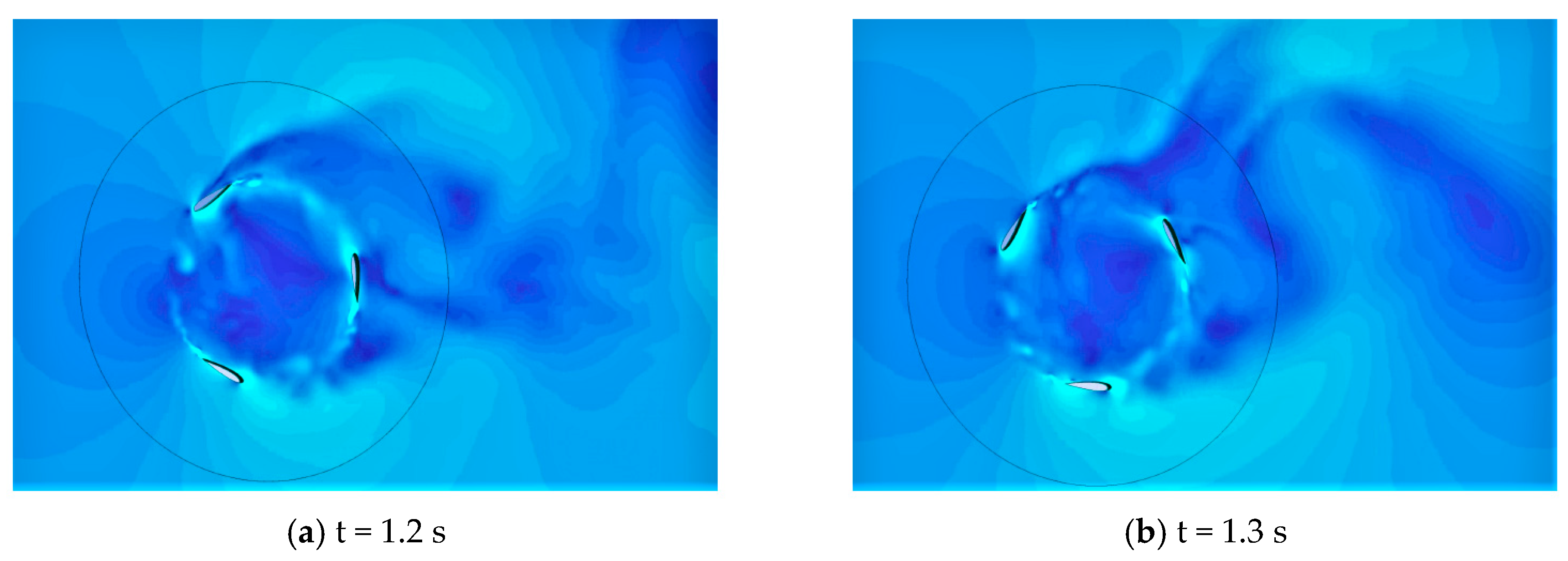
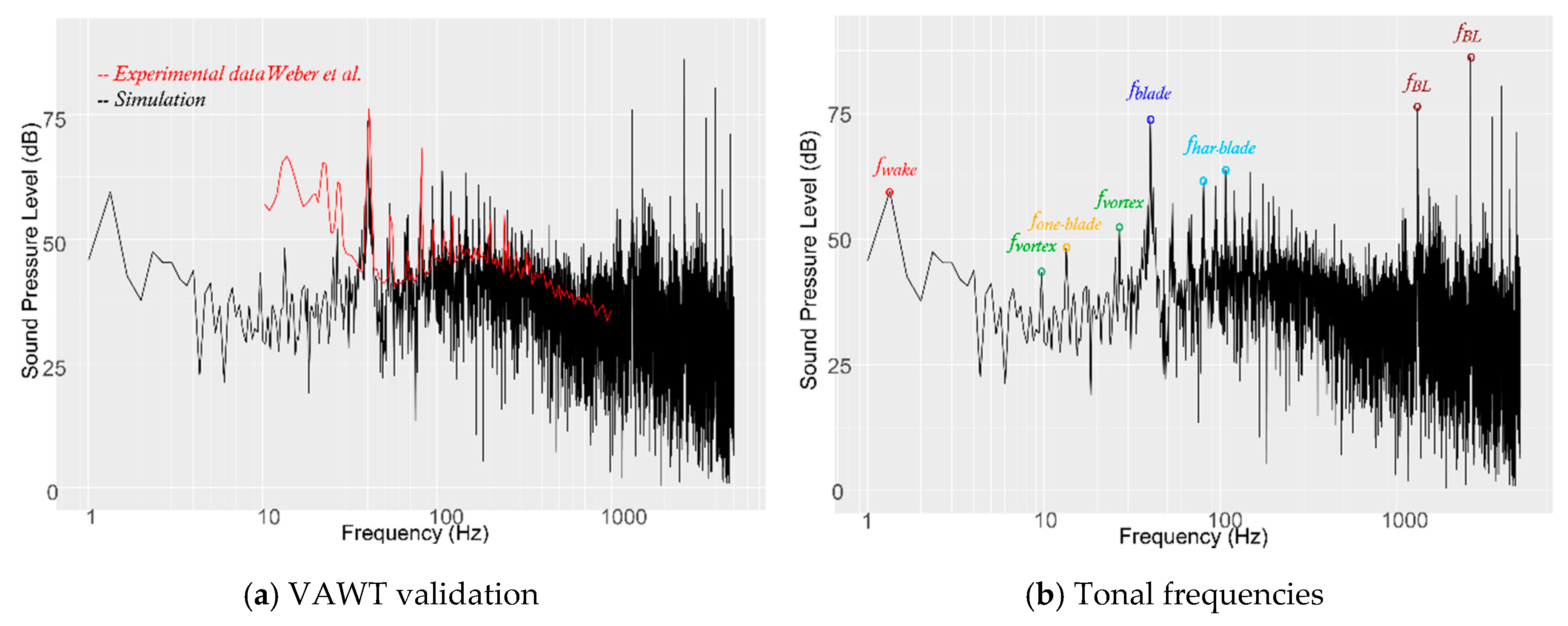
The complex flow field associated to a rotating isolated VAWT is illustrated in Figure 4, wind is from the left. It can be seen that various flow phenomena coexist and lead to complex shedding patterns. In what follows, we will quantify the main physical mechanisms leading to distinct tonal frequencies in the acoustic spectrum, but before this we compare our simulated results to experimental data, to validate our methodology.
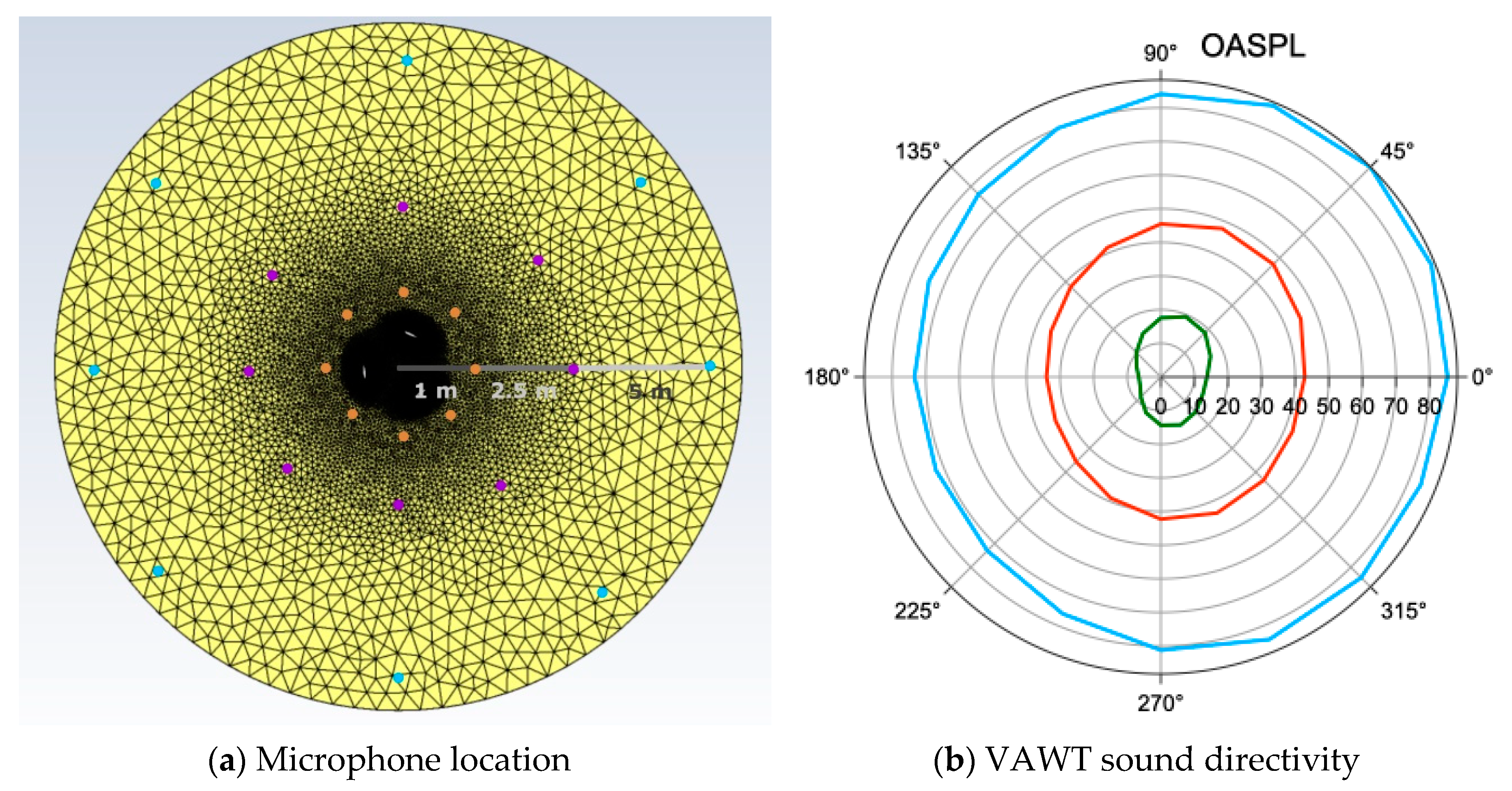
Figure 5 shows the sound pressure level spectrum for the isolated VAWT at a microphone placed 1 m downstream the axis of the turbine (see Figure 6a for the microphone location). We compare our simulations (black) to experimental data (red), which is extracted from [23]. Comparable experiments for similar VAWT can be found in [22]. The experiments were performed in the anechoic closed return (with an open test section) wind tunnel at the University of Erlangen-Nurnberg, which has a low turbulence level of 0.15%, see [23] for details. Our simulations use the flow conditions detailed in Table 1, which correspond to the "Full-scale" conditions detailed in [23].
Figure 5a illustrates the good agreement obtained between our simulations and the experiments. The main tonal frequencies are well captured for frequencies between 30 and 500 Hz. We see particular good agreement in capturing the main blade passing tonal frequency at 40 Hz. Our results do not agree well, with the experiments, at very low frequencies (<30 Hz), which is due to the background noise (i.e., wind tunnel fan noise) reported in the experiments, as shown in Figure 5 of [23], where the authors compared the sound pressure level spectrum measured with and without the turbine in the tunnel, to show that these low frequencies are identical when the turbine is not present. Our results agree well for frequencies where the background noise does not dominate, i.e., >30 Hz. At mid frequencies, we see various tonal frequencies and a relatively good match with experiments, even though the magnitude in our simulations is generally higher. Despite these discrepancies, this spectrum can help us to highlight the main physical mechanisms responsible for the acoustic tones.
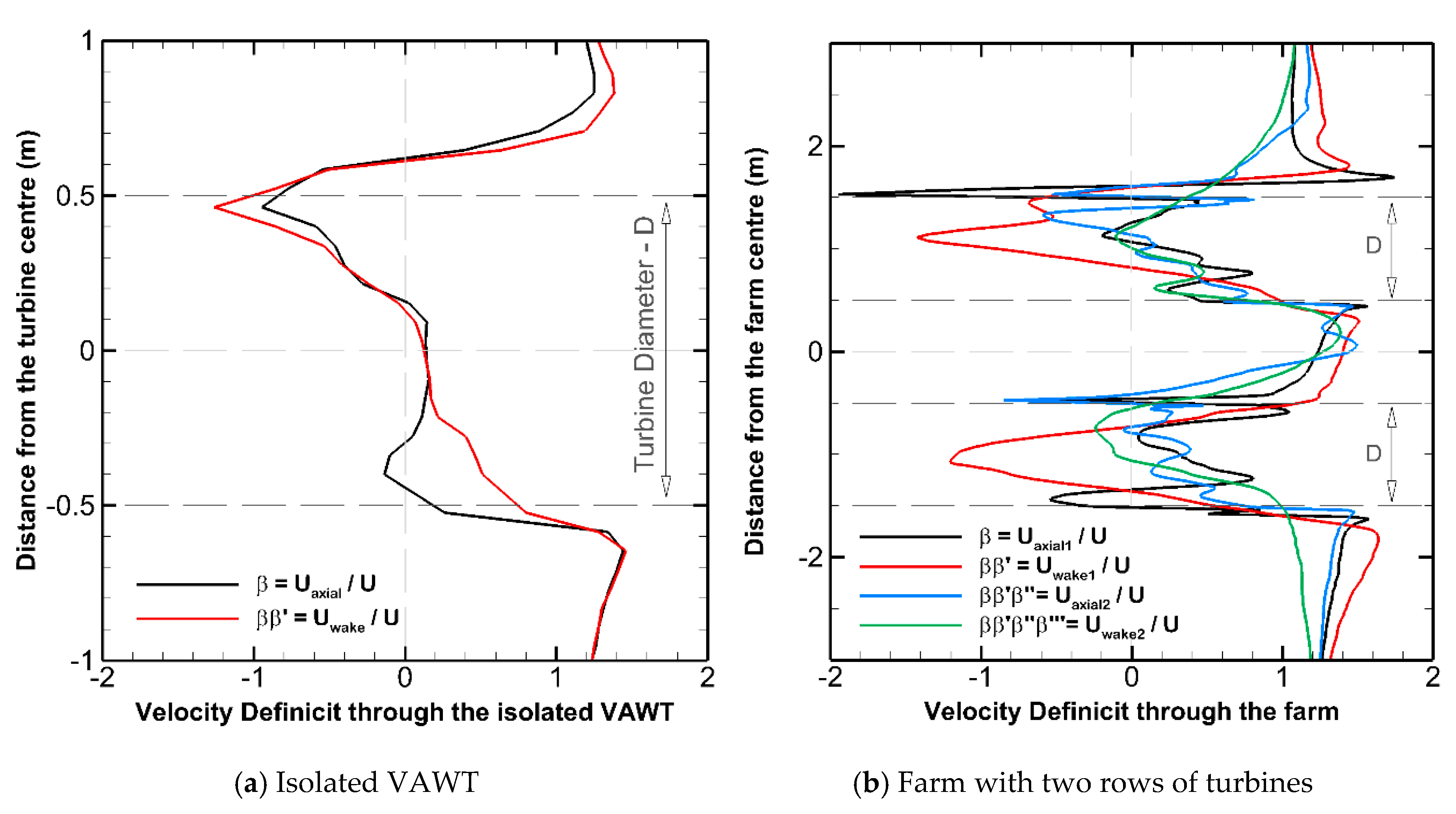
Now, we can start to relate the main frequencies of Figure 5, with physical mechanisms derived in Appendix B. We start by considering the turbine wake. Past the turbine, we observe a turbine wake with a large von Karman like flow structure, which due to the anti-clockwise rotation is slightly lifted upwards. We can provide an estimate for the low frequency associated to the VAWT wake ( f w a k e ) if we consider the Strouhal number S t = f D / U at R e = 4.67 × 10 5 for an equivalent circular cylinder given by Norberg [41]. From Norberg, we find S t = 0.19 , which relates to a dimensional frequency f w a k e = 1.33 Hz. This estimate agrees very well with the low frequency detected in the annotated Figure 5b. Additionally, we have included estimates for the main physical phenomena, including the wake time scaling in Table A3 in Appendix B. Following these estimates, we find f w a k e = 1 / τ w a k e = β β U / D = 7.0 Hz, if the velocity deficit at the front and rear passages are β β 1 . To obtain a frequency similar to f w a k e = 1.33 Hz, which was obtained using the cylinder approximation, the velocity deficit need to be β β 0.2 , which leads to f w a k e = 1.42 Hz. We depict the velocity deficits ( β and β β ) in Appendix B for the isolated VAWT in Figure A2a, where it can be seen that β and β β are not homogeneous across the diameter but that β β 0.2 may be a reasonable value when disregarding the high local velocities at the top of the turbine.
Near the trail of the rotating blades, wakes of small vortical structures can be observed in Figure 4. Particularly, distinct vortices are shed as the blades rotate at the front passage, and persist after being shed. The vortices shed during this half cycle are convected towards the rear half and may interact with the blades when in the upward rear cycle. This mechanisms of blade vortex interactions is complex and heavily dependent of the convection speed at the interior of the turbine (associated to turbine solidity) and turbulent diffusion that may help diffuse the vortices and alleviate their interaction with rotating blades. Theoretical estimates for the conditions of occurrence of blade-vortex interaction were provided by the second author in [16]. These estimates are included in Appendix B of this text and are used to predict the occurrence of blade-vortex interactions, which will inevitably lead to the generation of acoustic noise. We use the inverse of the estimate for the vortex time scale, from Table A2, to quantify the frequency associated to this phenomenon f v o r t e x = 1 / τ v o r t e x = ( λ U C L ) π 2 c 8.5 Hz if C L = 0.5 and 16.96 Hz when C L = 1 . Tonal frequencies within this ranges are present in Figure 5b. Let us note that the high rotational velocity, of the experimental and CFD set up, leads to very small variations in the geometrical angle of attack A o A g e o = tan 1 ( sin θ / cos θ + λ ) , which remains near 1.4° over the whole rotation cycle (i.e., dynamic stall is very unlikely). However, unsteady effects induced (for example) by wake oscillations, are likely to increase the effective angle of attack over the cycle leading to additional tones.
Table A2 provides an estimate of the blade-vortex interaction frequency as f B V = 1 / τ B V = β U D = 7 β . Assuming low turbine blockage β 1 , we obtain f B V = 7 Hz and f B V = 1.4 Hz if β 0.2 , which provides a range of possible tones. The frequencies for f v o r t e x are close to f B V and, for this reason, we group these vortex frequencies into f v o r t e x . These are included in Figure 5b.
We now calculate the geometric frequencies arising from the moving blades. The blade passing frequency (for only one blade) can be calculated easily from the turbine rotational speed f o n e b l a d e = ω / 2 π = 13.33 Hz. Of course having a three bladed turbine, we expect the actual blade passing frequency at f b l a d e = 3 f o n e b l a d e = 40 Hz. This is indeed the main tonal frequency f b l a d e highlighted in Figure 5b. The second and third harmonics of the main frequency are also highlighted as f h a r b l a d e for reference. Note that the second harmonic is clearly visible in the experimental data. Additional tonal frequencies can be identified after the main rotational frequency f b l a d e and are attributed to non-integer multiples of the identified frequencies (also known as inharmonic frequencies) but are likely resulting from the identified main physical phenomena.
Lastly, we identify high frequencies (>1 kHz) that we relate to boundary layer scales. Estimates, based on flat plate aerodynamics, are detailed in Appendix B and summarised in Table A1, for the boundary layer blade scaling. Using these, we can estimate the frequency associated to the boundary layer thickness f B L = 1 / τ B L = U λ ( Re b l a d e ) γ c 2.4 kHz. As reported in Table 1, the range of Reynolds numbers seen by the blades as they rotate (based on the chord and the combined free stream and rotational velocity) is R e b l a d e = 5.81 8.15 × 10 5 for all azimuthal angle, which is comparable to the Reynolds number of the isolated airfoil R e c = 10 5 studied in Section 3.1 and therefore tonal frequencies at low angles of attack are expected. As for the isolated airfoil (see Section 3.1), we follow Paterson et al. [39] and relate the shedding frequency to twice the boundary layer thickness. Consequently, the expected frequency is f B L = 1.2 kHz, which is not far from the frequencies depicted in Figure 5b ( 1 1.2 kHz). These high frequency tones have also been reported in [28]. At higher frequencies than f B L , harmonics and other small scale phenomena associated to the blade aerodynamics are observed. Due to the very high mesh requirement needed to capture such small flow structures, these very high tones are disregarded in what follows.
We complete the previous study with the noise directivity for the isolated VAWT. Figure 6a shows the microphone location and Figure 6b depicts the directivity plot for the three circular arrays of microphones. The figure shows the Overall Sound Pressure Level (OASPL) at each microphone; 180° denotes the turbine front and 0° the rear. We observe a monopole shape, where the directivity is shifted towards the rear for all microphone arrays, and is attributed to the turbine wake. The monopole type directivity is different from that of a horizontal axis turbines, where a dipole character, with predominance in the rotor perpendicular direction, dominates [42]. Additionally, the arrays located further away from the turbine show larger amplitudes in the cross-flow directions. This directivity seems to be governed by an unsteady loading, which radiates in the perpendicular direction to the incoming flow direction.

3.3. Aeroacoustic Sources for Four Vertical Axis Turbine in Close Proximity

In this section, we analyse the acoustic footprint of a group of four VAWTs, located in close proximity (or farm). As summarised in the introduction, previous works [9,10,11,12] have recommended the location of groups of VAWT in close proximity to enhance power extraction. Here we only consider one configuration and focus on the farm aeroacoustics.
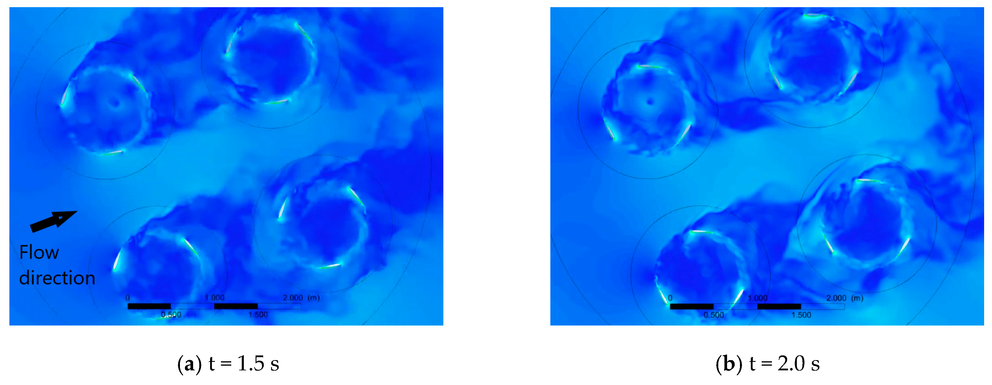
Each of the turbines is identical to the isolated VAWT analysed in the previous section, and therefore similar tonal frequencies, associated to the identified physics, are expected. Figure 7 show two snapshots of the highly unsteady flow over the group of turbines. We observe a more complex flow pattern than for the isolated turbine. The figure suggests that the wakes of the first row of turbines are not allowed to develop as they are ingested by the second row of turbines. Consequently, the second row sees a highly unsteady flow, which is likely to generate noise of unsteady loading character. After the second row, wakes develop but we fail to distinguish a clear von Karman like flow structure (as in the isolated VAWT), since individual wakes fuse into a unique wider farm-wake only 1–2 diameters after the second row of turbines.
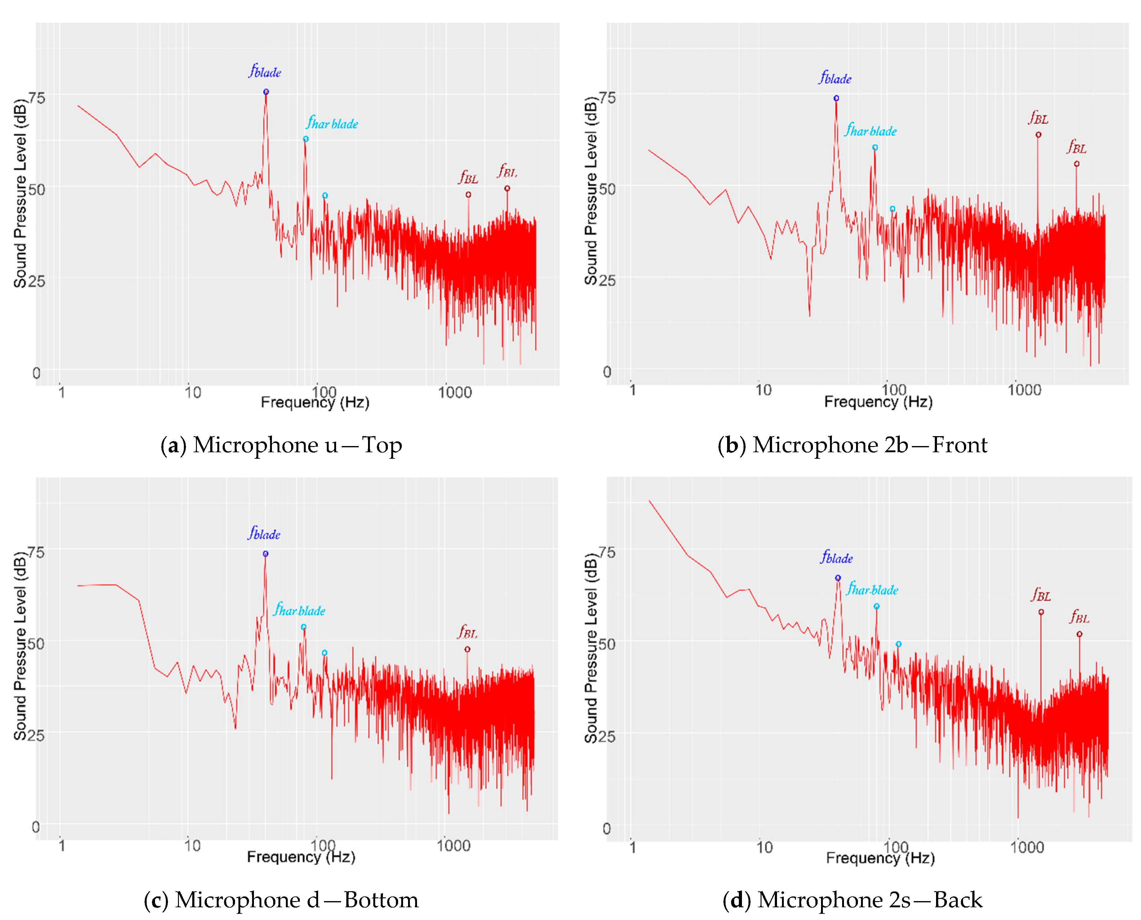
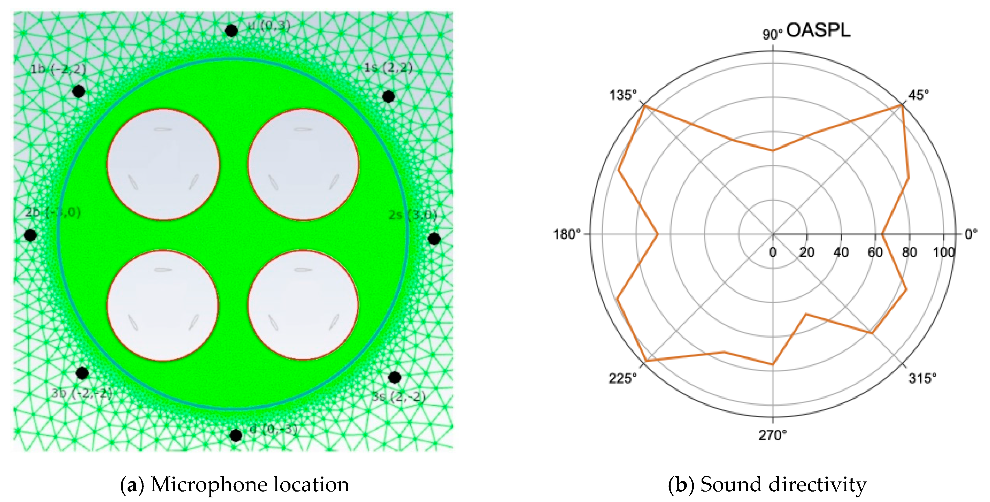
Figure 8 reports the sound pressure level spectra at four locations. These locations are depicted in Figure 9a and correspond to: top (microphone u ), front (microphone 2 b ), bottom (microphone d ) and back (microphone 2 s ) locations around the farm. As before, we have annotated the figures to highlight the main frequencies observed.
The wake time scaling of Table A3 in Appendix B was used for the individual turbine to obtain a wake frequency estimate of f w a k e = 1.42 Hz, if β β 0.2 . We can also find estimates for a farm with two rows of turbines, see Table A4. When considering two rows, the effective diameter of the farm can be approximated by 3D (three times the diameter of one turbine), and the farm-wake frequency (denoted wake2 in Table A4) can be approximated as one third of the frequency of the isolated turbine, which gives f w a k e f a r m = β β β β U 3 D 0.45 Hz, if β β β β 0.2 (see Figure A2 in Appendix B). We do not observe this tonal frequency in Figure 8, which is likely masked by the high levels of broadband noise, at very low frequencies.
The four microphones report the main blade passing frequency f b l a d e , whose amplitude is not larger than in the isolated case, which shows that there is no clear cumulative effect of having four turbines with identical blade passing frequency. This can be quantified by considering a linear combination of incoherent acoustic sources (see for example [42]), which results in the following augmented sound pressure level for the farm: L f a r m = 10 log 10 ( 4 ( p i n d / p r e f ) 2 ) = L i n d + 10 log 10 ( 4 ) , where p i n d is the RMS pressure of an individual turbine, p r e f = 0.00002 Pa is the reference pressure and L i n d = 10 log 10 ( ( p i n d / p r e f ) 2 ) is the sound pressure level of an individual turbine. In Figure 5 we observe that the main tonal amplitude for the individual turbines is L i n d 75 dB, and therefore if a linear superposition of the sources was to hold for the farm, we should observe in Figure 8 a peak of magnitude L f a r m 75 d B + 6 d B = 81 dB. However, the maximum amplitude observed in Figure 8 is 75 dB for all microphones, which suggests that a linear superposition of sources cannot be used to compute the overall farm footprint. Let us note that if we had considered coherent sources (instead of incoherent), the total noise would have been L f a r m = L i n d + 20 log 10 4 87 dB, which is even higher that for incoherent sources and much higher than measured.
Returning to the blade passing frequency, f b l a d e , we observe that it has smaller amplitude when measured at the back of the farm, where broadband noise tends to dominate, which relates to the high mixing and not clear flapping of the farm-wake. The second harmonic f h a r b l a d e is clearly visible in all spectra, but has a larger amplitude in microphones u and 2 b (Top and Front respectively). The third harmonic is almost indistinguishable in all microphones. Additional (integer or non-integer) harmonics cannot be clearly identified.
High frequency boundary layer tones f B L are found in all microphones, but the amplitude of this tone is 10 dB higher on the microphones located at the front ( 2 b ) and the back ( 2 s ) of the farm, which illustrates the particular directivity of this type of noise.
For completeness, we show in Figure 9b the directivity plot for the turbine farm. We show the Overall Sound Pressure Level (OASPL) at each microphone depicted in Figure 9a; 180° denotes the farm front and 0° the back. Overall, the OASPL amplitudes are larger in the farm case than in the isolated turbine. The directivity for the farm is different of that of the isolated turbine.
Here, we observe a quadrupole character, as opposed to the monopole directivity reported for the isolated VAWT. This is likely due to the superposition of four monopole, leading to a quadrupole directivity, in the farm case. Additionally, the directivity is shifted towards the front of the farm, which suggests that the wider wake, and associated enhanced mixing behind the turbine, tends to dissipate acoustic energy. Additionally, the highly unsteady flow field ingested by the second row, leads to unsteady loading noise that modifies the directivity for the farm. We conclude that the directivity for the farm is substantially different from the case of the isolated VAWT.

3.4. Human Perception of the Farm Acoustics

A-weighting represent the sensitivity of the human ear and shows that our perception at 40 Hz has to be weighted by −35 dB, see [42]. Both the individual turbine and the farm show a blade passing frequency of 75 dB (at 40 Hz), which may be A-weighted to give 40 dB(A). This level is not very high and may be ignored when designing VAWTs and farms for urban environments. However, if larger rotational speeds or turbines with more than three blades are considered, it is likely that the main blade-passing frequencies becomes irritating.
In the case presented here, the main cause of discomfort is associated to the boundary layer tones, with amplitudes of 60 dB at frequencies above 1000 Hz (where A-weighting does not attenuate the amplitude). These tones will be responsible of discomfort if the turbines are located in urban environments. Our study shows that farms are not likely to reduce these high frequency tones, but that these should be minimised when designing/selecting the airfoils of VAWTs.

4. Conclusions

We have simulated and analysed the aeroacoustic spectra for three configurations: an isolated NACA0012 airfoil, an isolated rotating vertical axis turbine and four vertical axis turbines in close proximity (or farm). This systematic study has helped to identify the noise sources in the various configurations, and associate physical mechanisms responsible of the aeroacoustic generation in vertical axis wind turbines and farms of turbines. This type of configuration is expected to become popular in urban environments, e.g., turbines on building roofs.
Differences between the isolated turbine and the group of turbines are reported. It has been shown that the superposition of individual sources does not hold for the acoustic amplitudes, the tonal frequencies and the sound directivities. Despite these differences, the isolated turbine provides information about most of tonal frequencies that are to be expected in the farm case: the blade passing frequency and the boundary layer tones. Additionally, a modified directivity for the farm is observed, with respect to the isolated turbine, and is attributed to the enhanced unsteady loadings and redirection (scattering) of noise due to the larger farm-wake, which also enhances mixing past the farm. We have not observed new tonal frequencies arising from the interaction from the four turbines but rather a decreased number of tones for mid-range frequencies. Despite the similarities between the isolated and farm spectra, it is clear that the farm case cannot be reduced to a linear superposition of noise sources extracted from isolated turbines.

Author Contributions

M.V.-M. and E.F.: Conceptualization, Methodology and Analysis; M.V.-M.: Simulations and Writing; E.F.: Writing, Reviewing, Editing, Resources and Funding. All authors have read and agreed to the published version of the manuscript.

Funding

No funding to acknowledge.

Acknowledgments

The authors acknowledge the cloud resources and technical assistance provided by ANSYS-Fluent to experiment with ANSYS Cloud, which has facilitated some of the larger presented cases. Additionally, the authors thank ANSYS for making available Academic Research licences that have enabled the simulation of small cases.

Conflicts of Interest

The authors declare no conflict of interest.

Appendix A. NACA0012 Airfoil and Tonal Frequency at Low Angles of Attack

The appearance of one or various tones and the mechanism controlling these tones, for the NACA0012 airfoil at 0°, has been a topic of debate for some time. On the one hand, Paterson et al. [39], performed an experimental study on NACA0012 and NACA0018 airfoils and reported a discrete tone, which was suggested to be related to the presence of a small separation bubble on the suction side, see Paterson et al. [39] and also Lowson et al. [43]. On the other hand, Arbey and Bataille [44] have reported, also experimentally, that the tonal peak is in fact a superposition of a broadband peak at a main frequency and a set of regularly spaced discrete frequencies. Later, Desquesnes et al. [45] observed two behaviours broadband with discrete frequencies or multiple tones (one main frequency and harmonics). They explained that this characteristic depends on the Reynolds number, angle of attack, and that two different types of acoustic spectrum can be observed: one which exhibits a broadband contribution with a dominant frequency together with a sequence of regularly spaced discrete frequencies, while the other one is only characterized by a simple broadband contribution. In fact, periodic modulation of the amplitude of the main tonal frequency produce secondary tones. The existence of separation bubbles, which are excited through a close loop mechanism by the trailing edge vortex shedding explained the discrepancies. Note that previous attributed this phenomenon to a laminar separation bubble and therefore is not related to turbulence or its modelling.
Our simulations use a WALE-LES model that introduces almost no turbulent viscosity near walls and laminar regions. For this reason, we believe that this laminar separation can be captured. In our simulations, we have observed the two behaviours. With a coarser mesh around the profile, we did not observe any tonal frequency, whilst the reported results use a fine grid that captures the main tonal frequency. We have only reported this last case, because we believe that is better suited for validation of the methodology.

Appendix B. Estimation of Flow Scales in Vertical Axis Wind Turbines

This section is a summary of the work detailed in [16,46,47] that describes the range of flow scales expected when simulating VAWTs, together with VAWT simulations and physical insights into blade-vortex interactions. Figure A1 presents a schematic illustration of the three physical spatial scales expected on VAWT flows: the blade scale, the vortex scale and wake scale. The blade scaling includes near wall scales and boundary layers, the vortex scaling considers vortex shedding and blade vortex interaction effects and finally the wake scaling includes the wake structure related to the turbine as a whole. In this section, estimates for the length, time and velocity scales for the different phenomena, are briefly summarised.
Figure A1. Flow scales in VAWT turbine flows. Turbine blades of chord c rotate with an angular velocity ω at a distance R from the turbine centre.
Energies 13 04148 g0a1

B.1. The Blade Scaling

We can estimate the VAWT’s length scales for the boundary layer using Blasius’ approximation [48] for the flow over a flat plate (zero pressure gradient). First, let us consider the rotational speed of the blades U r o t = ω R , where ω is the angular velocity and R the turbine radius. In addition, we define the tip speed ratio is defined as λ = U r o t / U , where U represents the free stream velocity. For simplicity, the velocity that the blade experiences can be estimated as U b l a d e = U r o t 2 + U 2 U r o t = λ U , which is a valid assumption for λ > > 1 (i.e., ignoring the free stream velocity U ). Then, Blasius approximation provides a boundary layer of thickness [48]: δ x / ( x U b l a d e ν ) γ = x / ( x λ U ν ) γ , where x is the distance from the leading edge, ν is the kinematic viscosity and the exponent γ relates to the boundary layer regime: γ = 1 / 2 for a laminar regime and γ = 1 / 5 for a turbulent boundary layer. Setting x = c (i.e., the blade chord), we can obtain a characteristic length scale for the blade B L = c ( Re b l a d e ) γ , where Re b l a d e = c U b l a d e ν is the Reynolds number based on the blade chord. An estimate for the time scale can be readily found: τ B L = B L U b l a d e = c U λ ( Re b l a d e ) γ . A summary of these scales is given in Table A1.
Table A1. Characteristic blade scales in VAWT turbines.
Length ScaleTime Scale Velocity Scale Reynolds Number
B L τ B L U B L = U b l a d e Re B L = Re b l a d e
c ( Re b l a d e ) γ c U λ ( Re b l a d e ) γ λ U c λ U ν

B.2. Vortex Scaling and Blade-Vortex Interaction

Vortex shedding and vortex impingement may play an important role in turbine performance. For VAWTs, a vortex created by the upstream half of the turbine may be convected downstream, interacting with the rear half of the turbine. An estimate for the scales corresponding to the vortex convection and the blade-vortex interaction is here detailed. Firstly, let us assume a two dimensional vortex with area A π 4 c 2 (the circular area covered by the two dimensional vortex), where c is the characteristic length (the blade chord and the diameter of the vortex) and with characteristic turn over time τ v o r t e x 2 π ω z , where ω z represents the vorticity magnitude. Approximating the vorticity as a function of the blade circulation and thus of the lift generated by the blade (Kutta-Joukowski theorem [49]), we can write ω z Γ A , with Γ = L ϱ U b l a d e representing the circulation and L the blade lift force, with ϱ the fluid density. Since L = 1 2 ϱ U b l a d e 2 c C L , with C L the blade lift coefficient, the characteristic vortex time can be expressed as: τ v o r t e x π 2 c ( λ U C L ) . Finally the characteristic velocity of the vortex can be estimated as U v o r t e x = v o r t e x τ v o r t e x λ U C L π 2 .
To estimate the lengths and times of the blade-vortex (BV) interactions, let us assume a vortex of diameter c that convects through the turbine at a velocity U a x i a l = β U , where β 1 represents the velocity deficit through the turbine ( β 1 for unblocked cases but may exceed 1 if blockage leads to accelerated flow through the turbine) and U a x i a l is the mean streamwise velocity component within the turbine. Note that β could be negative for VAWT if the flow is reversed after the front passage. In these cases we will assume the absolute value of velocities: | U a x i a l | = β | U | , which do not include explicitly for clarity. The time for a vortex to convect from the front half to the rear half (i.e., to travel the distance D = 2 R ) can be estimated as τ B V = B V U a x i a l = D β U . Table A2 summarises these scales.
Table A2. Characteristic vortex scales in VAWT turbines.
Length ScaleTime Scale Velocity Scale Reynolds Number
v o r t e x τ v o r t e x U v o r t e x Re v o r t e x
c π 2 c ( λ U C L ) λ U C L π 2 c λ U C L π 2 ν
B V τ B V U B V Re B V
D D β U β U D β U ν

B.3. Wake Scaling

VAWT wake development is of foremost importance since the performance of downstream turbines may be influenced by the shape and strength of upstream generated flow structures, influencing aeroacoustic propagation. We can estimate the length and time scales for the near wake assuming a wake of diameter D = 2 R , and a velocity in the wake region as U w a k e = β β U , where in addition to the induction factor β introduced in the previous section, β 1 is defined as the velocity deficit due to the rear half blade passage. The characteristic scales are detailed in Table A3.
Table A3. Characteristic wake scales in VAWT turbines.
Length ScaleTime Scale Velocity Scale Reynolds Number
w a k e τ w a k e U w a k e Re w a k e
D D β β U β β U D β β U ν

B.4. Farm Scaling

We can now gather together the above estimates to propose new ones when considering two rows of turbines. We now consider a first row of turbines with characteristic velocities: U a x i a l 1 , U w a k e 1 and a second row of turbines with velocities U a x i a l 2 , U w a k e 2 . As before, we can derive estimates in terms of the velocity deficit β s at each step within the farm, such that U a x i a l 1 = β U , U w a k e 1 = β β U , U a x i a l 2 = β β β U and U w a k e 2 = β β β β U , where now U w a k e 1 β = U a x i a l 2 and U a x i a l 2 β = U w a k e 2 . Considering a characteristic length scale of the farm of w a k e 2 = 3 D , we can complete a table of scales for two rows of turbines.
Table A4. Characteristic wake scales for two rows of VAWT turbines.
Length ScaleTime Scale Velocity Scale Reynolds Number
w a k e 2 τ w a k e 2 U w a k e 2 Re w a k e
3 D 3 D β β β β U β β β β U 3 D β β β β U ν

B.5. VAWT Wake and Wake-Farm Scaling

The above estimates can be calculated for the isolated VAWT and the farm. For the isolated turbine, we extract flow velocities in cross-flow sections at the turbine center and 0.2D after the turbine and plot the instantaneous velocity deficits in Figure A2a. It can be seen that β and β β are not homogeneous across the diameter and that | β β | 0.2 0.3 may be a reasonable value when disregarding the high local velocities at the top of the turbine. The velocity deficits for the farm are shown in Figure A2b. Here, the cross-flow sections are at the turbine centres for the two rows, in between turbines and 0.2D after the second row. The instantaneous velocity deficits show a more complex behaviour and significant changes across the farm diameter. Disregarding local high peaks, reasonable estimates are | β β | 0.2 or | β β β β | 0.2 . It is interesting to note that in the farm case, the velocity deficit after the first row ( | β β | 1 ) is larger that when only considering one isolated turbine, and is attributed to the interaction with the second row. Finally, these instantaneous estimates provide guidelines for the analysis of the acoustic tones but a more thorough study would be necessary to better quantify these velocity deficits.
Figure A2. Velocity deficits for individual VAWT and farm of turbines: (a) Isolated VAWT and (b) Farm with two rows of turbines.
Energies 13 04148 g0a2

References

  1. Bhutta, M.M.A.; Hayat, N.; Farooq, A.U.; Ali, Z.; Jamil, S.R.; Hussain, Z. Vertical axis wind turbine–A review of various configurations and design techniques. Renew. Sustain. Energy Rev. 2012, 16, 1926–1939. [Google Scholar] [CrossRef]
  2. Eriksson, S.; Bernhoff, H.; Leijon, M. Evaluation of different turbine concepts for wind power. Renew. Sustain. Energy Rev. 2008, 12, 1419–1434. [Google Scholar] [CrossRef]
  3. Kumar, R.; Raahemifar, K.; Fung, A.S. A critical review of vertical axis wind turbines for urban applications. Renew. Sustain. Energy Rev. 2018, 89, 281–291. [Google Scholar] [CrossRef]
  4. Ouro, P.; Runge, S.; Luo, Q.; Stoesser, T. Three-dimensionality of the wake recovery behind a vertical axis turbine. Renew. Energy 2019, 133, 1066–1077. [Google Scholar] [CrossRef] [Green Version]
  5. Posa, A. Dependence of the wake recovery downstream of a Vertical Axis Wind Turbine on its dynamic solidity. J. Wind Eng. Ind. Aerodyn. 2020, 202, 104212. [Google Scholar] [CrossRef]
  6. Zanforlin, S.; Nishino, T. Fluid dynamic mechanisms of enhanced power generation by closely spaced vertical axis wind turbines. Renew. Energy 2016, 99, 1213–1226. [Google Scholar] [CrossRef] [Green Version]
  7. Alexander, A.S.; Santhanakrishnan, A. Mechanisms of power augmentation in two side-by-side vertical axis wind turbines. Renew. Energy 2020, 148, 600–610. [Google Scholar] [CrossRef]
  8. Brownstein, I.D.; Wei, N.J.; Dabiri, J.O. Aerodynamically Interacting Vertical-Axis Wind Turbines: Performance Enhancement and Three-Dimensional Flow. Energies 2019, 12, 2724. [Google Scholar] [CrossRef] [Green Version]
  9. Hezaveh, S.H.; Bou-Zeid, E.; Dabiri, J.; Kinzel, M.; Cortina, G.; Martinelli, L. Increasing the Power Production of Vertical-Axis Wind-Turbine Farms Using Synergistic Clustering. Bound. Layer Meteorol. 2018, 169, 275–296. [Google Scholar] [CrossRef] [Green Version]
  10. Zheng, H.D.; Zheng, X.; Zhao, S. Arrangement of clustered straight-bladed wind turbines. Energy 2020, 200, 117563. [Google Scholar] [CrossRef]
  11. Barnes, A.; Hughes, B. Determining the impact of VAWT farm configurations on power output. Renew. Energy 2019, 143, 1111–1120. [Google Scholar] [CrossRef]
  12. Rezaeiha, A.; Montazeri, H.; Blocken, B. A framework for preliminary large-scale urban wind energy potential assessment: Roof-mounted wind turbines. Energy Convers. Manag. 2020, 214, 112770. [Google Scholar] [CrossRef]
  13. Wagner, S.; Bareiss, R.; Guidati, G. Wind Turbine Noise; Springer: Berlin/Heidelberg, Germany, 1996. [Google Scholar]
  14. Doolan, C.; Moreau, D.J.; Brooks, L.A. Wind turbine noise mechanisms and some concepts for its control. Acoust. Aust./Aust. Acoust. Soc. 2012, 40, 7–13. [Google Scholar]
  15. Ferrer, E.; Munduate, X. Wind turbine blade tip comparison using CFD. J. Phys. Conf. Ser. 2007, 75, 7–13. [Google Scholar] [CrossRef]
  16. Ferrer, E.; Willden, R.H. Blade-wake interactions in cross-flow turbines. Int. J. Mar. Energy 2015, 11, 71–83. [Google Scholar] [CrossRef] [Green Version]
  17. Bangga, G.; Dessoky, A.; Wu, Z.; Rogowski, K.; Hansen, M.O. Accuracy and consistency of CFD and engineering models for simulating vertical axis wind turbine loads. Energy 2020, 206, 118087. [Google Scholar] [CrossRef]
  18. Le Clainche, S.; Ferrer, E. A Reduced Order Model to Predict Transient Flows around Straight Bladed Vertical Axis Wind Turbines. Energies 2018, 11, 566. [Google Scholar] [CrossRef] [Green Version]
  19. Ferrer, E.; Browne, O.M.; Valero, E. Sensitivity Analysis to Control the Far-Wake Unsteadiness Behind Turbines. Energies 2017, 10, 599. [Google Scholar] [CrossRef] [Green Version]
  20. Ferrer, E.; Clainche, S.L. Simple Models for Cross Flow Turbines. In Recent Advances in CFD for Wind and Tidal Offshore Turbines; Springer: Berlin/Heidelberg, Germany, 2019. [Google Scholar] [CrossRef]
  21. Du, L.; Ingram, G.L.; Dominy, R.G. A review of H-Darrieus wind turbine aerodynamic research. Proceedings of the Institution of Mechanical Engineers, Part C. J. Mech. Eng. Sci. 2019, 233, 7590–7616. [Google Scholar] [CrossRef] [Green Version]
  22. Weber, J.; Tautz, M.; Becker, S.; Huppe, A.; Kaltenbacher, M. Computational Aeroacoustic Simulations of Small Vertical Axis Wind Turbine. In Proceedings of the Inter–Noise and Noise–Con Congress and Conference Proceedings, InterNoise16, Hamburg, Germany, 21–24 August 2016; pp. 3858–4854. [Google Scholar]
  23. Weber, J.; Becker, S.; Scheit, C.; Grabinger, J.; Kaltenbacher, M. Aeroacoustics of Darrieus wind turbine. Int. J. Aeroacoustics 2015, 14, 883–902. [Google Scholar] [CrossRef] [Green Version]
  24. Pearson, C. Vertical Axis Wind Turbine Acoustics. Ph.D. Thesis, Cambridge University Engineering Department, Cambridge, UK, 2013. [Google Scholar]
  25. Ottermo, F.; Möllerström, E.; Nordborg, A.; Hylander, J.; Bernhoff, H. Location of aerodynamic noise sources from a 200kW vertical-axis wind turbine. J. Sound Vib. 2017, 400, 154–166. [Google Scholar] [CrossRef]
  26. Pearson, C.E.; Graham, W. Investigation of The Noise Sources on A Vertical Axis Wind Turbine Using An Acoustic Array. In Proceedings of the 19th AIAA/CEAS Aeroacoustics Conference, Berlin, Germany, 27–29 May 2013. [Google Scholar]
  27. Möllerström, E.; Ottermo, F.; Hylander, J.; Bernhoff, H. Noise Emission of a 200 kW Vertical Axis Wind Turbine. Energies 2015, 9, 19. [Google Scholar] [CrossRef] [Green Version]
  28. Ghasemian, M.; Nejat, A. Aero-acoustics prediction of a vertical axis wind turbine using Large Eddy Simulation and acoustic analogy. Energy 2015, 88, 711–717. [Google Scholar] [CrossRef]
  29. Mohamed, M. Aero-acoustics noise evaluation of H-rotor Darrieus wind turbines. Energy 2014, 65, 596–604. [Google Scholar] [CrossRef]
  30. Su, J.; Lei, H.; Zhou, D.; Han, Z.; Bao, Y.; Zhu, H.; Zhou, L. Aerodynamic noise assessment for a vertical axis wind turbine using Improved Delayed Detached Eddy Simulation. Renew. Energy 2019, 141, 559–569. [Google Scholar] [CrossRef]
  31. Mohamed, M. Reduction of the generated aero-acoustics noise of a vertical axis wind turbine using CFD (Computational Fluid Dynamics) techniques. Energy 2016, 96, 531–544. [Google Scholar] [CrossRef]
  32. Mohamed, M. Criticism study of J-Shaped Darrieus wind turbine: Performance evaluation and noise generation assessment. Energy 2019, 177, 367–385. [Google Scholar] [CrossRef]
  33. Botha, J.; Shahroki, A.; Rice, H. An implementation of an aeroacoustic prediction model for broadband noise from a vertical axis wind turbine using a CFD informed methodology. J. Sound Vib. 2017, 410, 389–415. [Google Scholar] [CrossRef] [Green Version]
  34. Lighthill, S.M.J. On Sound Generated Aerodynamically. In Proceedings of the Royal Society of London. Series A, Mathematical and Physical Sciences, London, UK, 20 March 1952; Royal Society: London, UK, 1952. [Google Scholar]
  35. Ffwocs Williams, J.E.; Hawkings, D.L. Sound generation by turbulence and surfaces in arbitrary motion. Philosophical Transactions of the Royal Society of London. Ser. A. Math. Phys. Sci. 1969, 264, 321–342. [Google Scholar]
  36. Goldstein, M.E. A Generalized Acoustic Theory. J. Fluid Mech. 2003, 488, 315–333. [Google Scholar] [CrossRef] [Green Version]
  37. Wang, D.; Atlar, M.; Sampson, R. An experimental investigation on cavitation, noise, and slipstream characteristics of ocean stream turbines. Proceedings of the Institution of Mechanical Engineers-Part A. J. Power Energy 2006, 221, 219–231. [Google Scholar] [CrossRef]
  38. Jones, L.E.; Sandberg, R.D. Numerical analysis of tonal airfoil self-noise and acoustic feedback-loops. J. Sound Vib. 2011, 330, 6137–6152. [Google Scholar] [CrossRef]
  39. Paterson, R.W.; Vogt, P.; Fink, M.; Munch, C. Vortex Noise of Isolated Airfoils. J. Aircr. 1973, 10, 296–302. [Google Scholar] [CrossRef]
  40. Rodríguez, I.; Lehmkuhl, O.; Borrell, R.; Oliva, A. Direct numerical simulation of a NACA0012 in full stall.International. J. Heat Fluid Flow 2013, 43, 194–203. [Google Scholar] [CrossRef] [Green Version]
  41. Norberg, C. Fluctuating lift on a circular cylinder: Review and new measurements. J. Fluids Struct. 2003, 17, 57–96. [Google Scholar] [CrossRef]
  42. Möser, M. Engineering Acoustics: An Introduction to Noise Control; Springer: Berlin/Heidelberg, Germany, 2004. [Google Scholar]
  43. Lowson, M.; Fiddes, S.; Nash, E. Laminar boundary layer aero-acoustic instabilities. In Proceedings of the 32nd Aerospace Sciences Meeting and Exhibit, Reno, NV, USA, 22 August 2012. [Google Scholar] [CrossRef]
  44. Arbey, H.; Bataille, J. Noise generated by airfoil profiles placed in a uniform laminar flow. J. Fluid Mech. 1983, 134, 33–47. [Google Scholar] [CrossRef] [Green Version]
  45. Desquesnes, G.; Terracol, M.; Sagaut, P. Numerical investigation of the tone noise mechanism over laminar airfoils. J. Fluid Mech. 2007, 591, 155–182. [Google Scholar] [CrossRef]
  46. Ferrer, E. A high order Discontinuous Galerkin–Fourier Incompressible 3D Navier–Stokes Solver with Rotating Sliding Meshes for Simulating Cross-Flow Turbines. Ph.D. Thesis, University of Oxford, Oxford, UK, 2012. [Google Scholar]
  47. Ferrer, E.; Le Clainche, S. Flow Scales in Cross-Flow Turbines. In CFD for Wind and Tidal Offshore Turbines; Springer: Berlin/Heidelberg, Germany, 2015. [Google Scholar]
  48. Schlichting, H. Boundary Layer Theory; McGraw-Hill: New York, NY, USA, 1979. [Google Scholar]
  49. Anderson, J. Fundamentals of Aerodynamics, 4th ed.; McGraw-Hill: New York, NY, USA, 2005. [Google Scholar]
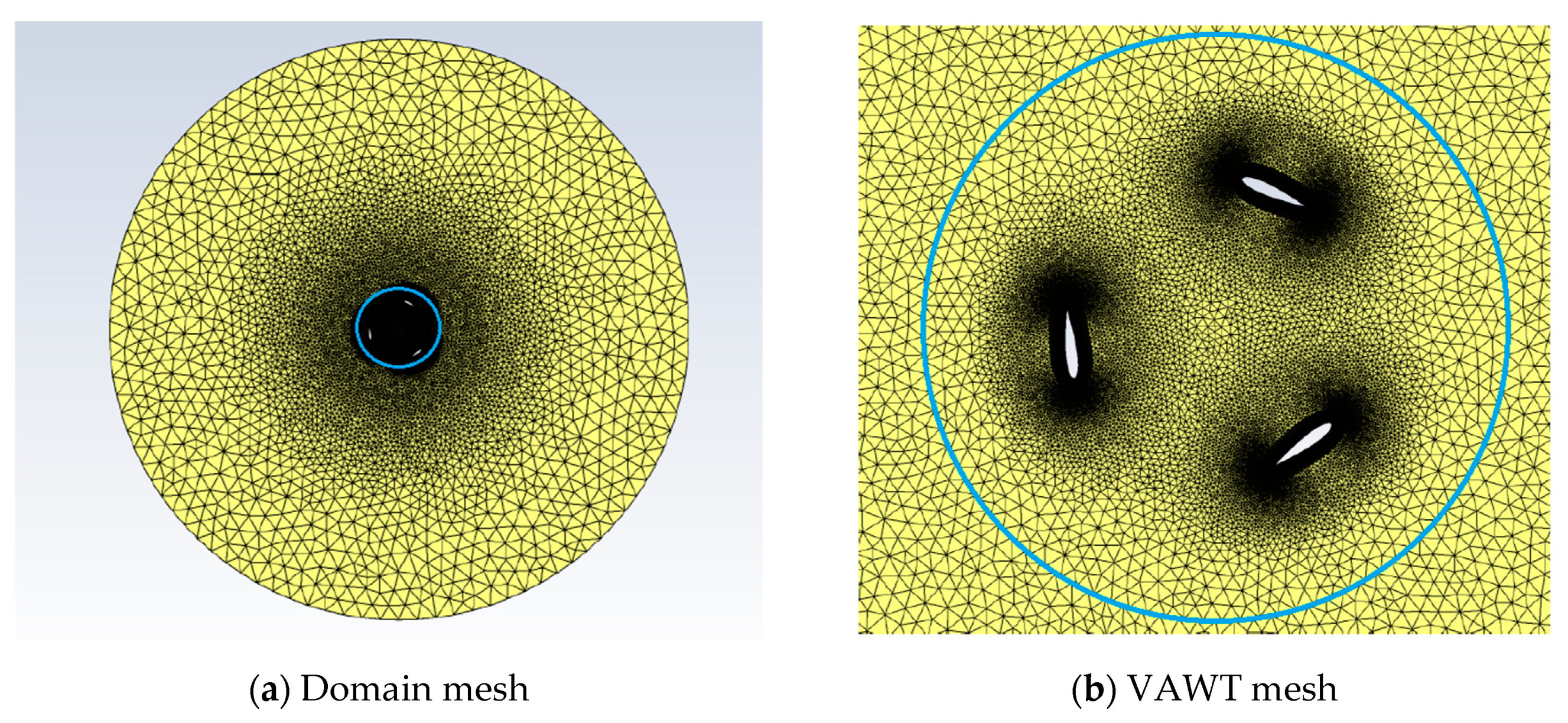
Figure 1. Mesh for isolated VAWT: (a) Domain mesh and (b) VAWT mesh.
Energies 13 04148 g001
Figure 2. Mesh for group of four VAWTs in close proximity (or farm): (a) Domain mesh, (b) Mesh for four VAWTs in close proximity and (c) Detail of the blades.
Energies 13 04148 g002
Figure 3. Power spectral density spectra for isolated NACA0012 airfoil at Re = 1 × 10⁵, microphone located at 0.5 m above the mid-chord of the airfoil: (a) Validation with DNS data at 0° [38] and (b) Black and red curves are our LES + FWH at angle of attack 20° and 0°, respectively.
Energies 13 04148 g003
Figure 4. Velocity magnitude flow field for isolated VAWT at two instants at time: (a) t = 1.2 s and (b) 1.3 s.
Energies 13 04148 g004
Figure 5. Sound Pressure Level for an isolated VAWT: (a) Comparison of experimental (red) [23] and our LES + FWH simulations (black), and (b) Annotated version highlighting the main physical frequencies in the VAWT.
Energies 13 04148 g005
Figure 6. (a) Microphone location and (b) Sound directivity for an isolated VAWT. Curves quantify the Overall Sound Pressure Level (OASPL) at microphones located at 1 (blue), 2.5 (red) and 5 (green) meter radius from the turbine centre; 180° denotes the turbine front and 0° the rear.
Energies 13 04148 g006
Figure 7. Velocity magnitude flow field for group of VAWTs in close proximity at two instants in time: (a) t = 1.5 s and (b) 2.0 s.
Energies 13 04148 g007
Figure 8. Sound Pressure Level at various microphone locations (shown in Figure 9a) for the group of VAWTs in close proximity: (a) Microphone u—Top, (b) Microphone 2b—Front, (c) Microphone d—Bottom and (d) Microphone 2s—Back.
Energies 13 04148 g008
Figure 9. (a) Microphone location and (b) sound directivity for a group of VAWTs (or farm) in close proximity. The curve quantifies the Overall Sound Pressure Level (OASPL) at the microphones located at a three meter radius from the turbine centre; 180° denotes the turbine front and 0° the rear.
Energies 13 04148 g009
Table 1. Flow conditions for the NACA0012, the isolated VAWT and the group of four VAWTs in close proximity.
NACA0012 (Sharp Trailing Edge)
Domain size (m): 200 × 200 × 0.1 (C-type mesh)
Number of mesh elements: 253.080
Reynolds number (chord based): R e c = 1 × 10 5
Blade Chord (m): c = 1
Angle of Attack (degrees): 0°
Isolated Vertical Axis Wind Turbine
Domain size (m): 20 × 20 × 0.1 (O-type mesh)
Number of mesh elements: 460.740
Reynolds number (Diameter based): R e D = 4.67 × 10 5
Profiles used for blades: NACA0018 (blunt trailing edge)
Turbine Diameter (m): D = 1
Number of blades: 3
Blade Chord (m): c = 0.25
Rotational Velocity (rad/s): ω = 83.776
Wind speed (m/s): U = 7
Tip speed ratio: λ = 6
Range of Reynolds numbers (blade-chord based) for all azimuths:
5.81 × 10 5 R e b l a d e 8.15 × 10 5
Group of four Vertical Axis Wind Turbines (or farm)
Domain size (m): 20 × 20 × 0.1 (O-type mesh)
Number of mesh elements: 5.053.400
VAWT configuration: as for the individual turbine
Separation between turbines (m): 2 (square shape distribution)