Electronically Controlled Actuators for a Micro Wind Turbine Furling Mechanism †

 ,
,  and
and 
Abstract
:
1. Introduction
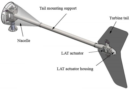
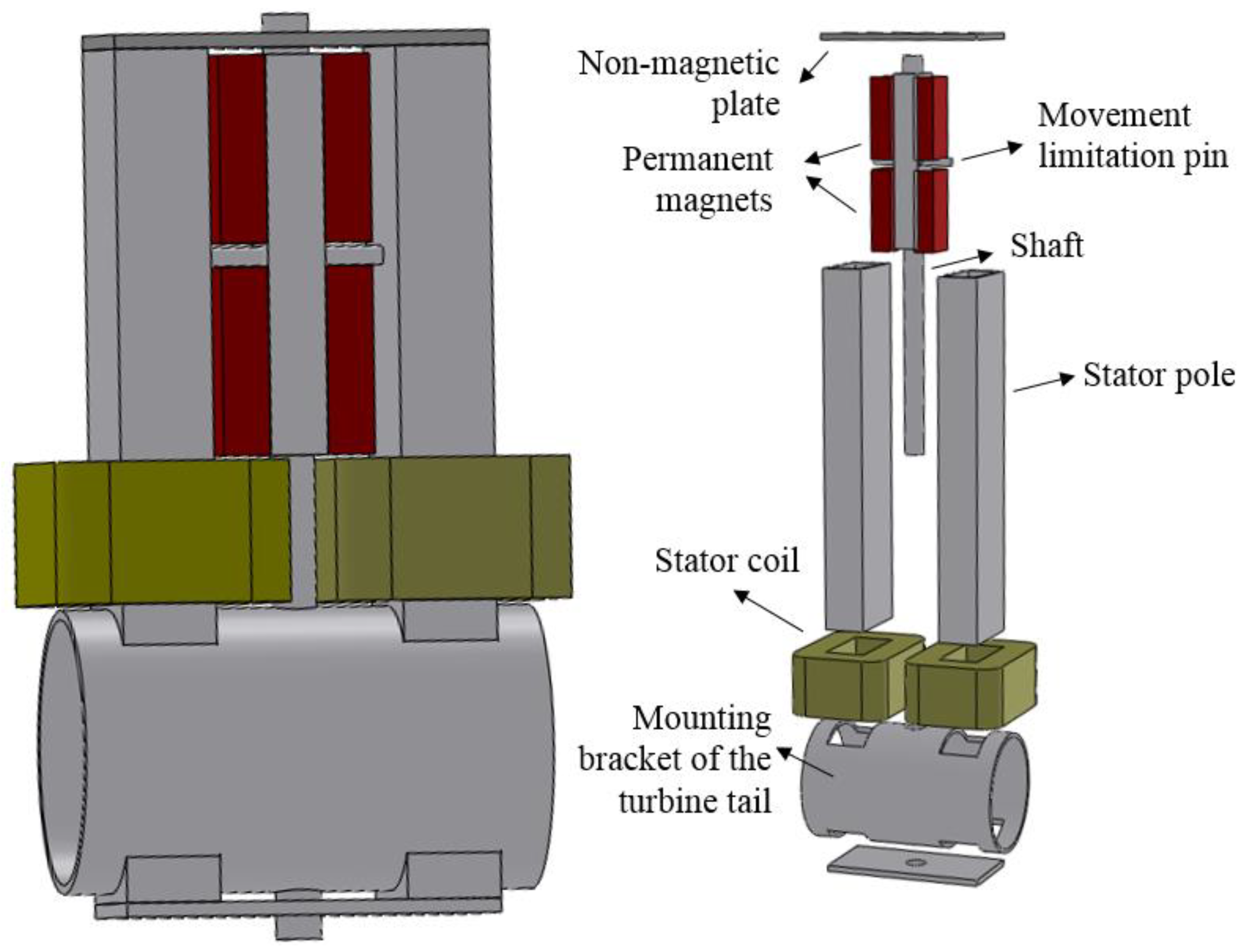
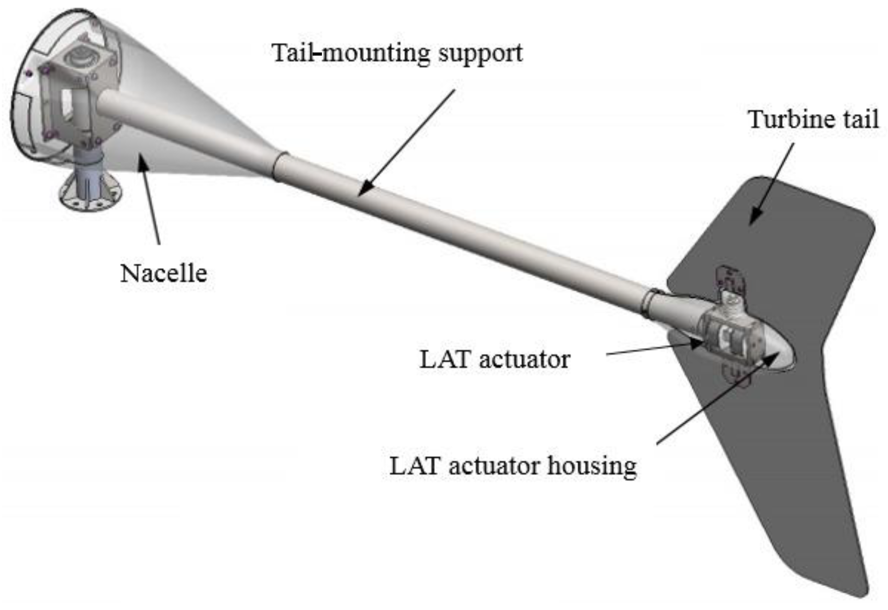
2. Limited-Angle Torque Electromechanical Actuator
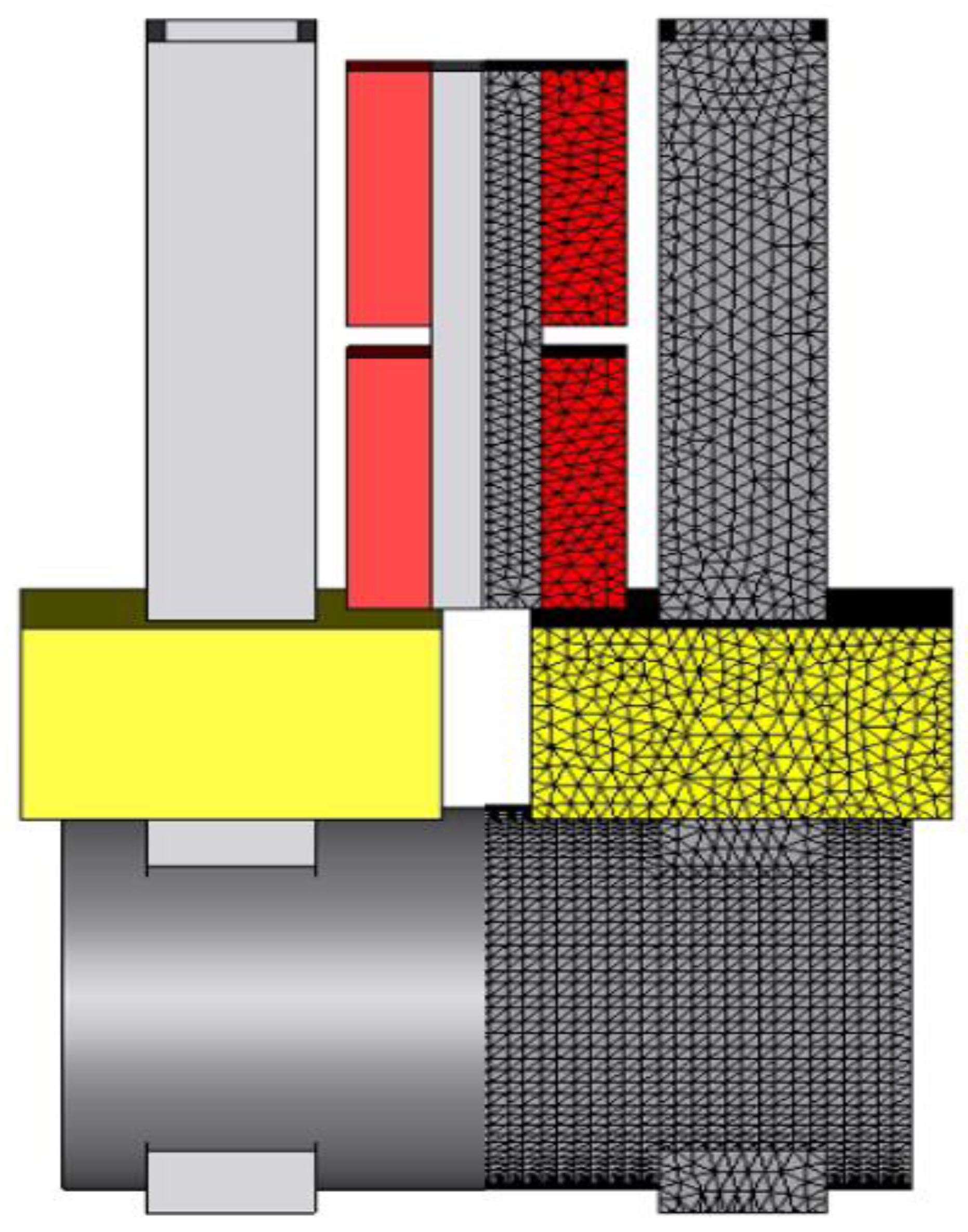
2.1. Design of the LAT Electromechanical Actuator
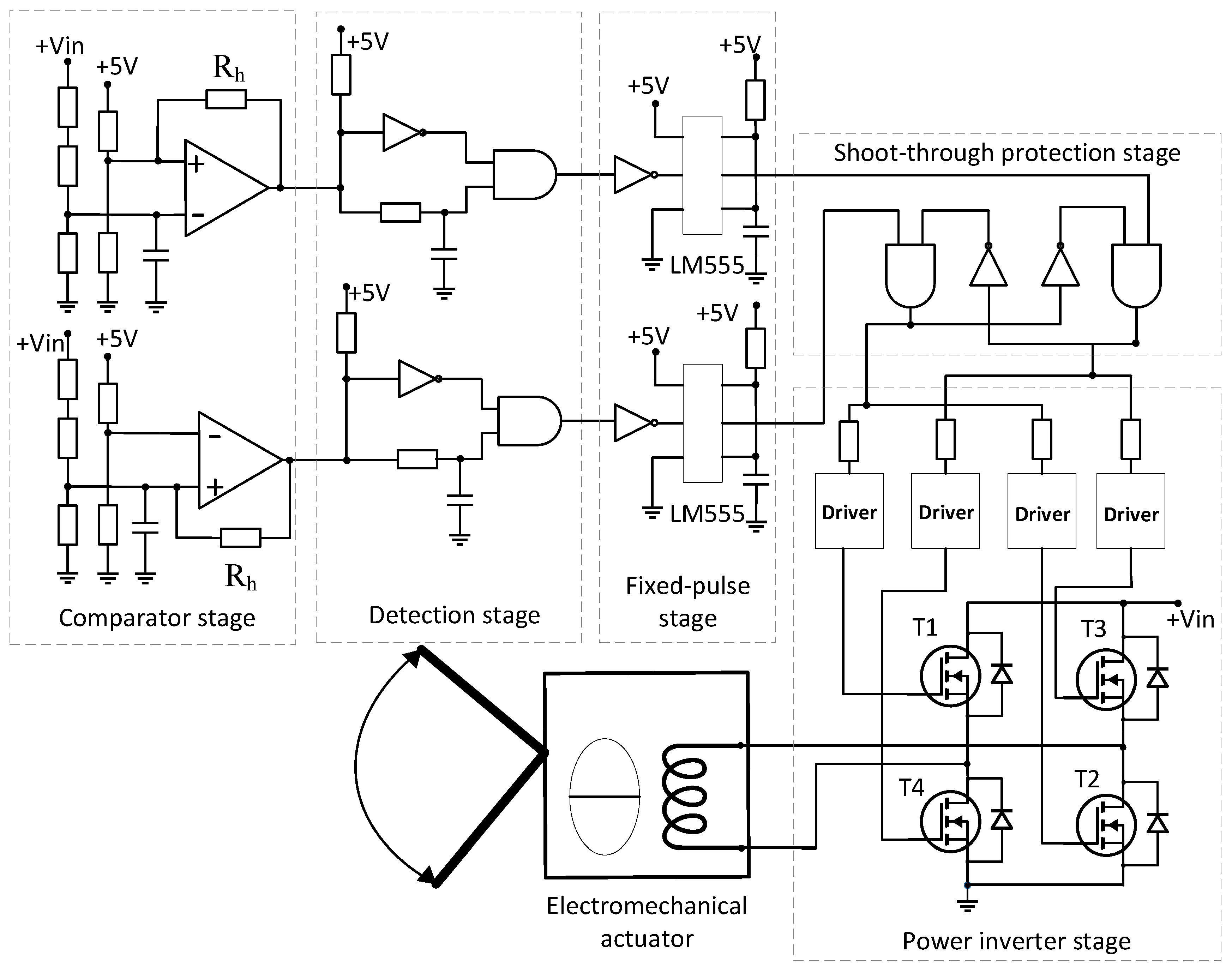
2.2. Electronic Circuit for LAT Electromechanical Actuator Control
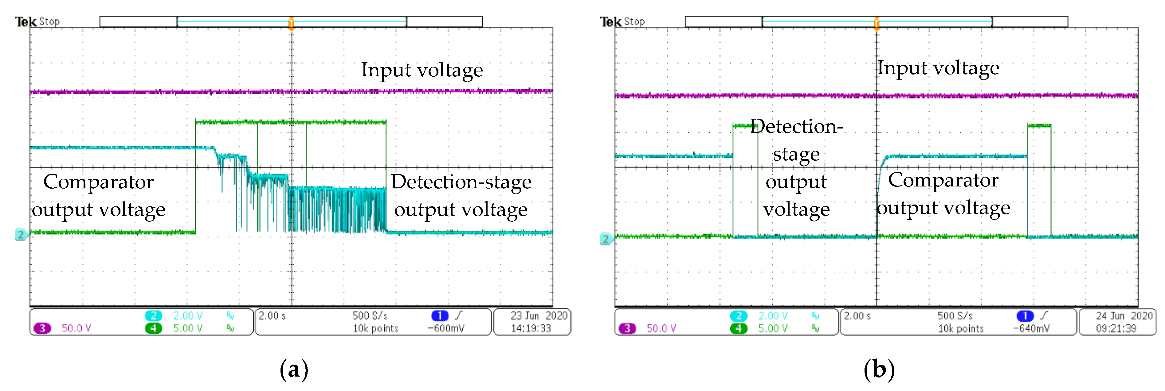
- 190 V—minimum detection voltage (Vmin)
- 210 V—maximum detection voltage (Vmax).
3. Geared Stepper Motor Actuator and the Electronic Circuit for Angular Control
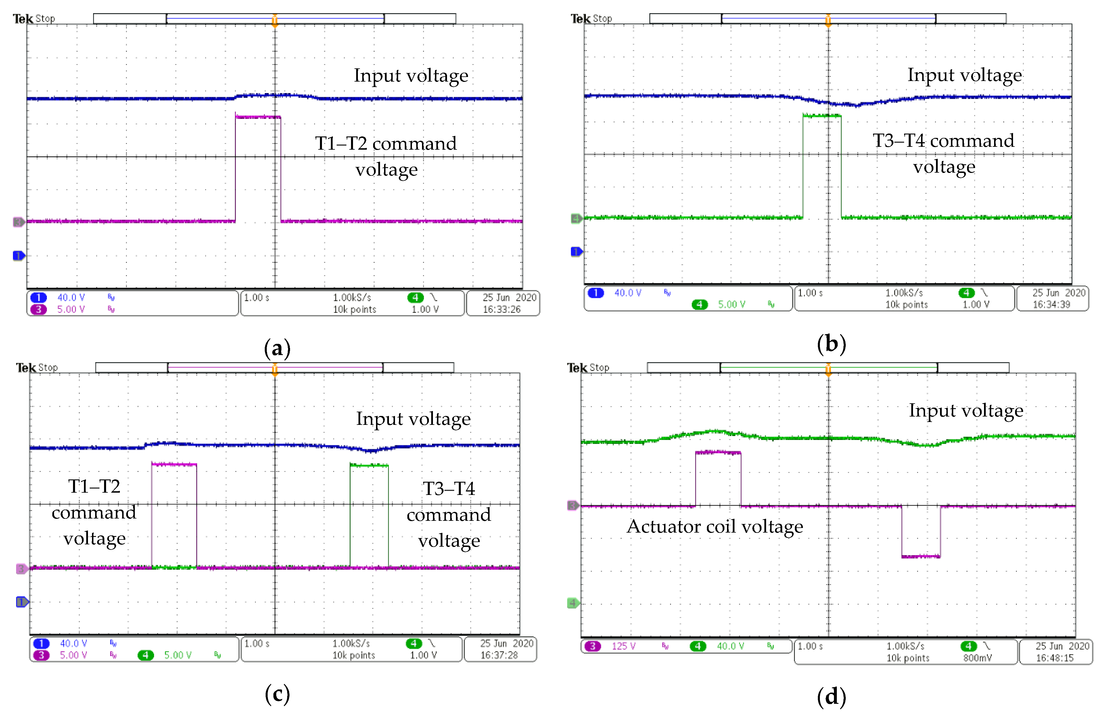
- 190 V—minimum detection voltage (Vmin)
- 200 V—nominal voltage for the detection stage (Vnom)
- 210 V—first maximum voltage level (Vmax.1)
- 215 V—second maximum voltage level (for supplementary protection) (Vmax.2).
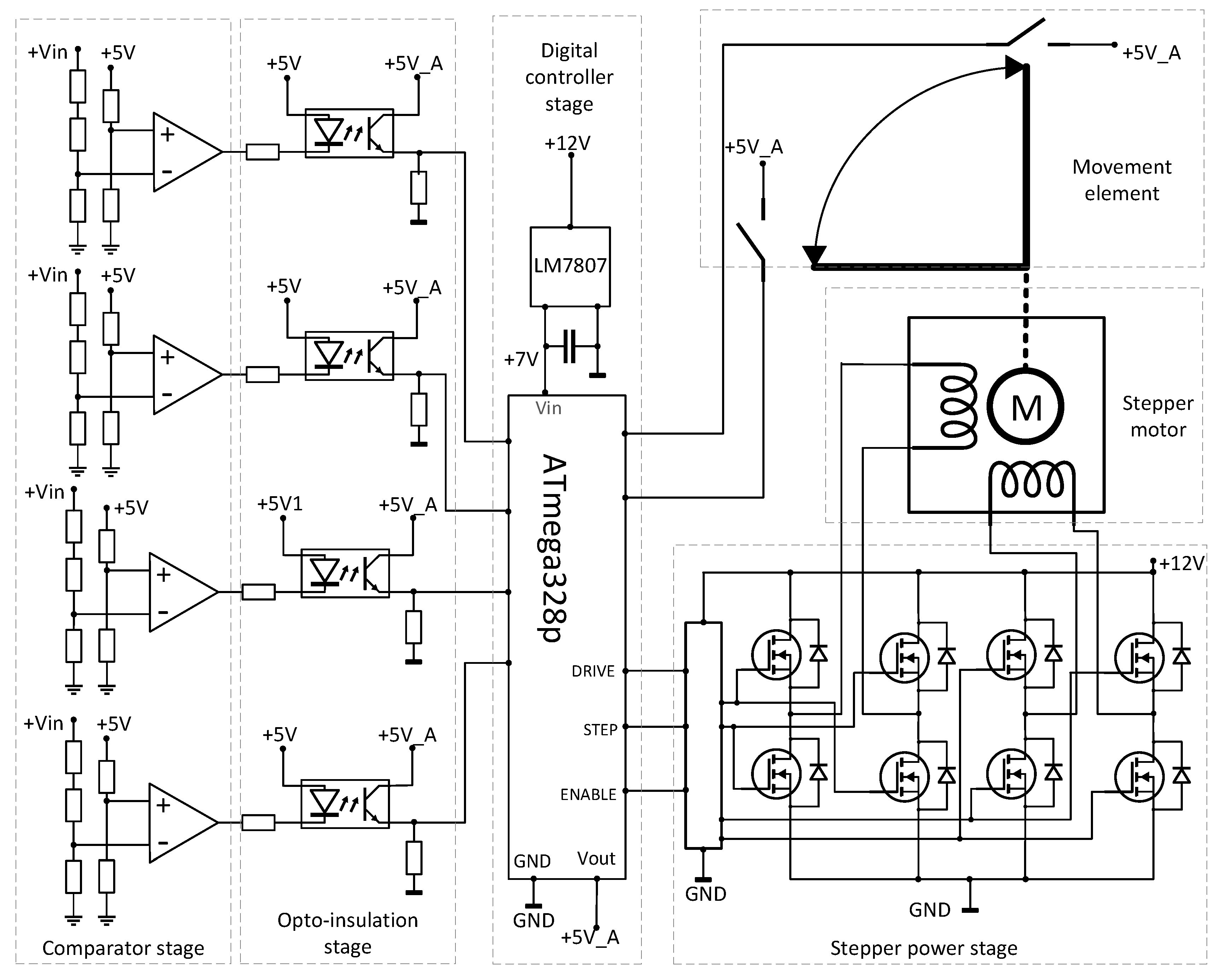
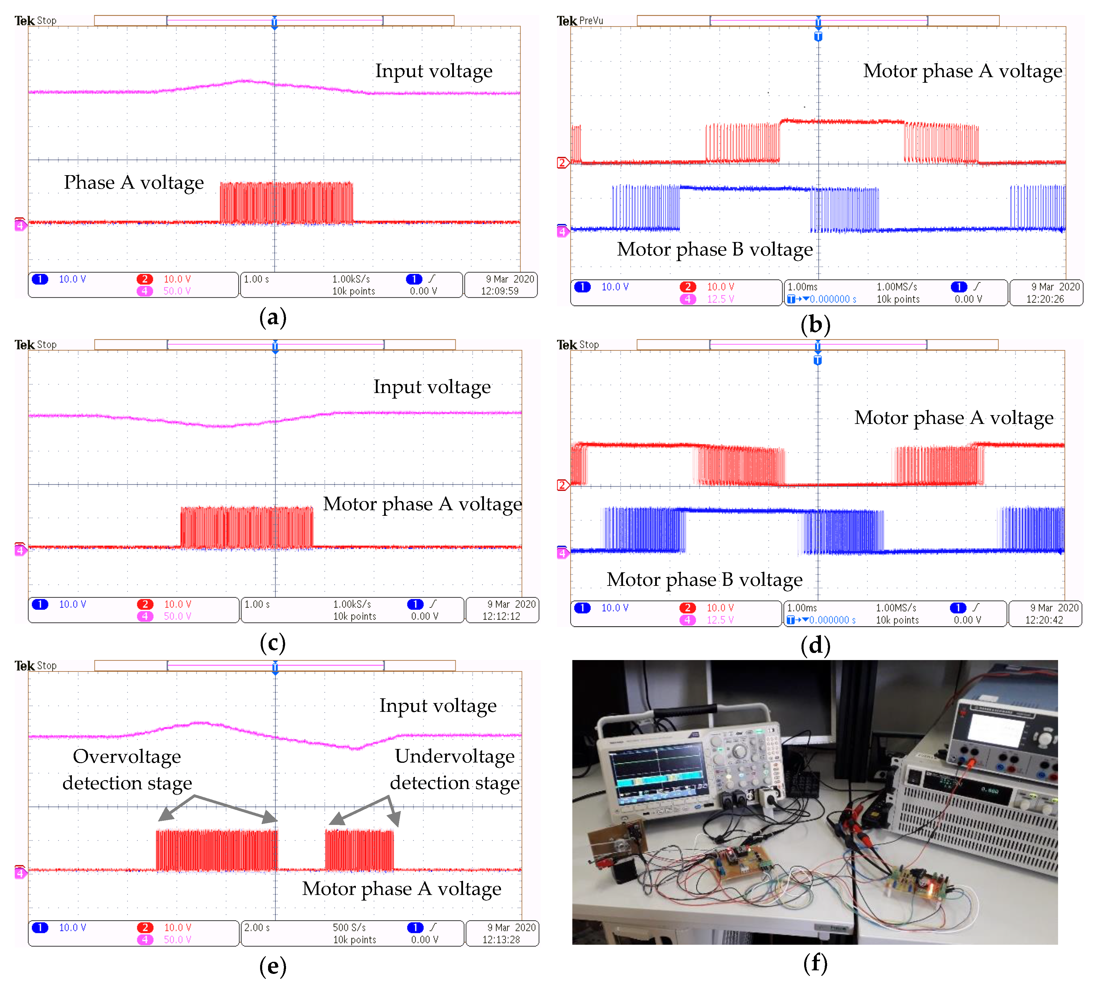
- Enable: A signal that activates both H-bridge circuits when the input state is low, and when it is high, the H-bridges are locked; the enable signal is in a high state until the overvoltage detection stage starts, meaning that the Vmax.1 value of the input voltage is reached. During the overvoltage detection stage, the output signal is low until the Vnom level is reached. Similarly, the high state is present until the undervoltage detection stage starts, meaning that the Vmin value of the input voltage is reached. During the undervoltage detection stage, the output signal is low until the Vnom level is reached again.
- Drive: A signal by which the rotation direction of the stepper motor can be changed. If the state is high, then the motor rotates clockwise. This is obtained during the overvoltage detection stage and when the Vmax.1 voltage level is reached. If the Vmax.2 voltage is also reached, it means that the stepper needs to perform all the rotational steps to obtain a 90° angle as quickly as possible. If the drive signal is in the low state, the motor rotates anticlockwise. This is obtained during the undervoltage detection stage and when the Vmin level is reached.
- Step: A signal that represents the command pulse or the increment motor step. The slope of the incremental steps is set to a low value so that it responds adequately in relation to the usual voltage behavior. For protection purposes, if the value Vmax.2 is reached, the slope time is increased so that the 90° angle is reached as soon as possible.
4. Discussion
5. Patents
Author Contributions
Funding
Conflicts of Interest
References
- Mohammad, E.; Rouzbeh, S.; Rezvan, A.; Mostafa, S.S. Numerical Investigation of the Savonius Vertical Axis Wind Turbine and Evaluation of the Effect of the Overlap Parameter in Both Horizontal and Vertical Directions on Its Performance. Symmetry 2019, 11, 821. [Google Scholar]
- Muljiadi, E.; Forsyth, T.; Butterfield, C.P. Soft-Stall Control Versus Furling Control for Small Wind Turbine Power Regulation. In Proceedings of the Windpower ’98, Bakersfield, CA, USA, 27 April–1 May 1998. [Google Scholar]
- Wang, T.; Yang, W.; Yuan, X.; Teichmann, R. A Redundant Electrical Braking System for Wind Turbine Generators. In Proceedings of the European Conference on Power Electronics and Applications, Aalborg, Denmark, 2–5 September 2008. [Google Scholar]
- Matsui, Y.; Sugawara, A.; Sato, S.; Takeda, T.; Ogura, K. Braking Circuit of Small Wind Turbine Using NTC Thermistor under Natural Wind Condition. In Proceedings of the 7th International Conference on Power Electronics and Drive Systems, Bangkok, Thailand, 27–30 November 2007. [Google Scholar]
- Sugawara, A.; Yamamoto, K.; Yoshimi, T.; Sato, S.; Tsurumaki, A.; Ito, T. Research for Electric Brake Using NTC Thermistors on Micro Wind Turbine. In Proceedings of the 12th International Power Electronics and Motion Control Conference, Portoroz, Slovenia, 30 August–1 September 2006; pp. 1597–1601. [Google Scholar]
- Gong, S.; Gao, C.; Chen, Z.; Zhang, J.; Ji, F. Research on Gentle Electric Brakes Using PWM and FET Control Circuits on Micro Wind Turbines. In Proceedings of the IEEE 2nd Advanced Information Technology, Electronic and Automation Control Conference (IAEAC), Chongqing, China, 25–26 March 2017; pp. 1737–1741. [Google Scholar]
- Cuches, J.P. Rotary Actuator. U.S. Patent 3039027A, 12 June 1962. [Google Scholar]
- Cuches, J.P.; Wiiage, M.; Henry, R. Angular Displacement Solenoid. U.S. Patent 3221191, 30 November 1965. [Google Scholar]
- Oudet, C.; Prudham, D. Monophase Electromagnetic Rotary Actuator of Travel between 60 and 120 Degrees. U.S. Patent 5334893A, 2 August 1994. [Google Scholar]
- Biwersi, S.; Gandel, P. Hybrid Single-Phase Bistable Rotary Actuator. E.P. Patent 1581991B1, 13 March 2013. [Google Scholar]
- Mohammadi, E.; Fadaeinedjad, R.; Moschopoulos, G. A Study of Power Electronic Based Stall and Electromechanical Yaw Power Control Strategies in Small-Scale Grid-Connected Wind Turbines. In Proceedings of the 2018 IEEE Applied Power Electronics Conference and Exposition (APEC), San Antonio, TX, USA, 4–8 March 2018; pp. 2323–2329. [Google Scholar] [CrossRef]
- Breban, S.; Teodosescu, P.D.; Neag, A.V.; Chirca, M. Electromechanical Actuator with Electronic Control Device 2018. Romanian Patent 131166B1, 30 August 2018. [Google Scholar]
- Chirca, M.; Drancă, M.; Teodosescu, P.D.; Breban, Ş. Limited-Angle Electromechanical Actuator for Micro Wind Turbines Overspeed Protection. In Proceedings of the 2019 11th International Symposium on Advanced Topics in Electrical Engineering (ATEE), Bucharest, Romania, 28–30 March 2019. [Google Scholar] [CrossRef]
- Ionica, I.; Modreanu, M.; Boboc, C.; Morega, A. Tridimensional Modeling for a DC, Limited Angle, Torque Motor of Size 16. In Proceedings of the 2016 International Conference and Exposition on Electrical and Power Engineering (EPE 2016), Iasi, Romania, 20–22 October 2016. [Google Scholar]
- Analog Devices. Available online: https://www.analog.com/en/products/ltc6993-1.html (accessed on 30 June 2020).


| Parameter | Value |
|---|---|
| Supply voltage | 200 V |
| Number of turns/coil | 450 |
| Coil resistance/coil | 2.8 Ω |
| Rated current RMS | 13.34 A |
| Coil connection type | Series |
| Overspeed Protection System | ON-OFF Bipolar Actuator | Geared Stepper Motor-Based Actuator |
|---|---|---|
| Cost | low | low |
| Actuator complexity | low | medium |
| Electronic control complexity | low | medium |
| Energy harvested at high speed | medium | high |
| Power consumption when active | high | low |
| Reliability | high | medium |
| Weight | high | low |
| Volume | high | low |
© 2020 by the authors. Licensee MDPI, Basel, Switzerland. This article is an open access article distributed under the terms and conditions of the Creative Commons Attribution (CC BY) license (http://creativecommons.org/licenses/by/4.0/).
Share and Cite
Chirca, M.; Dranca, M.; Oprea, C.A.; Teodosescu, P.-D.; Pacuraru, A.M.; Neamtu, C.; Breban, S. Electronically Controlled Actuators for a Micro Wind Turbine Furling Mechanism. Energies 2020, 13, 4207. https://doi.org/10.3390/en13164207
Chirca M, Dranca M, Oprea CA, Teodosescu P-D, Pacuraru AM, Neamtu C, Breban S. Electronically Controlled Actuators for a Micro Wind Turbine Furling Mechanism. Energies. 2020; 13(16):4207. https://doi.org/10.3390/en13164207
Chicago/Turabian StyleChirca, Mihai, Marius Dranca, Claudiu Alexandru Oprea, Petre-Dorel Teodosescu, Alexandru Madalin Pacuraru, Calin Neamtu, and Stefan Breban. 2020. "Electronically Controlled Actuators for a Micro Wind Turbine Furling Mechanism" Energies 13, no. 16: 4207. https://doi.org/10.3390/en13164207
APA StyleChirca, M., Dranca, M., Oprea, C. A., Teodosescu, P.-D., Pacuraru, A. M., Neamtu, C., & Breban, S. (2020). Electronically Controlled Actuators for a Micro Wind Turbine Furling Mechanism. Energies, 13(16), 4207. https://doi.org/10.3390/en13164207