Development of Simulation Tool for Ground Source Heat Pump Systems Influenced by Ground Surface
Abstract
:1. Introduction
2. Calculation Model for Ground Source Heat Pump Systems Influenced by Ground Surface
2.1. Overview of Ground Temperature Calculation
2.2. Overview of Ground Temperature Calculation in Simulation Tool
2.3. Calculation Method for Ground Source Heat Pump System
- (1)
- Indoor unit
- (2)
- GSHP unit
- (3)
- GHE
3. Thermal Response Test to Validate Calculation Result
3.1. Thermal Response Test
3.2. Calculation Conditions
3.3. Result and Discussion
4. Evaluation on Influence of Surface Temperature during Thermal Response Test
4.1. Calculation Conditions
4.2. Result and Discussion
5. Evaluation on Influence of Ground Surface on GSHP System Performance
5.1. Calculation Conditions
5.2. Result and Discussion
6. Conclusions
- (1)
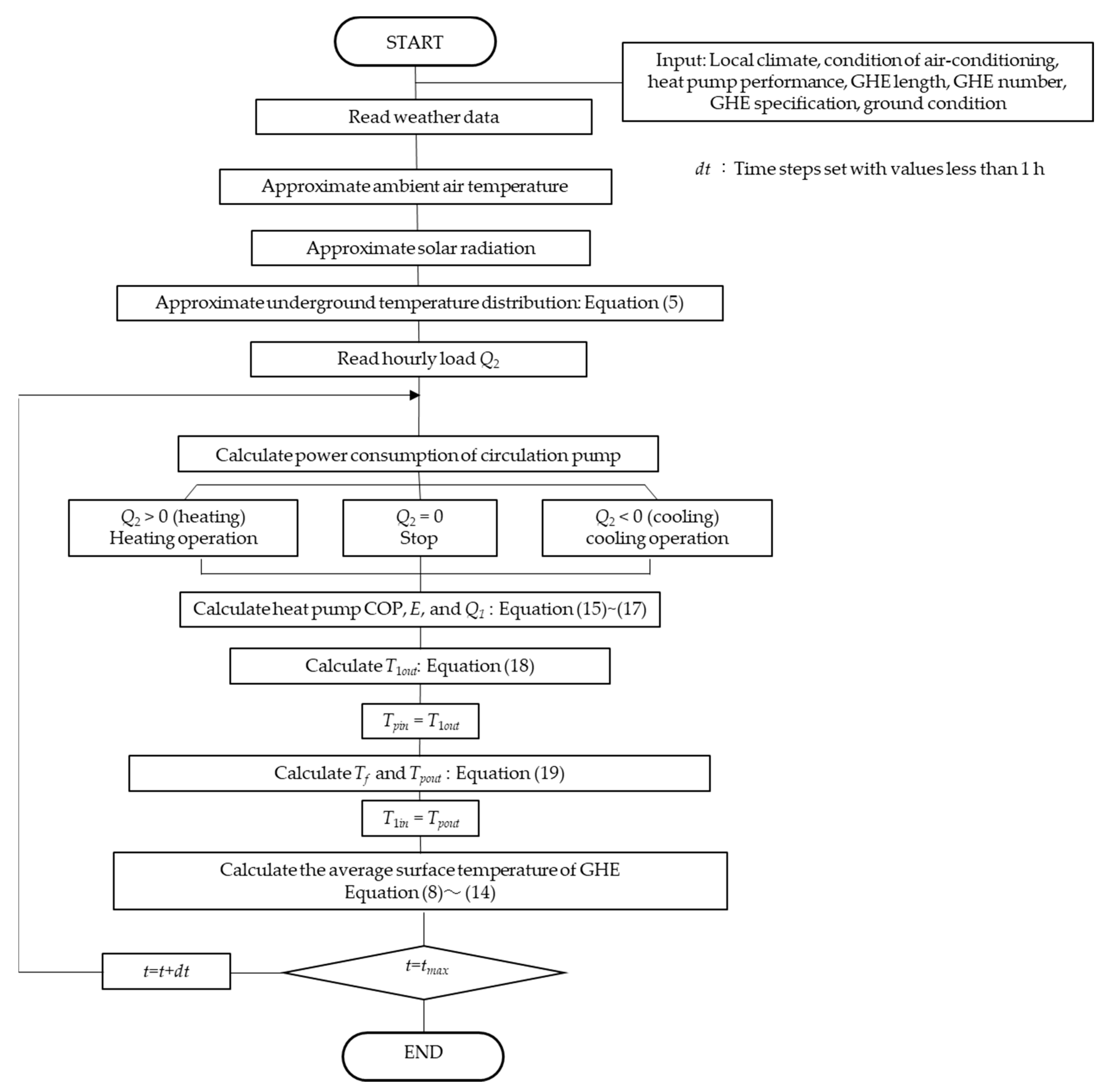
- By applying the superposition theorem, the authors developed a GHE calculation model considering the influence of the ground surface. In addition, the GHE calculation model was combined with a simulation tool for a GSHP system. The outlines of the calculation model for a short GHE were explained.
- (2)
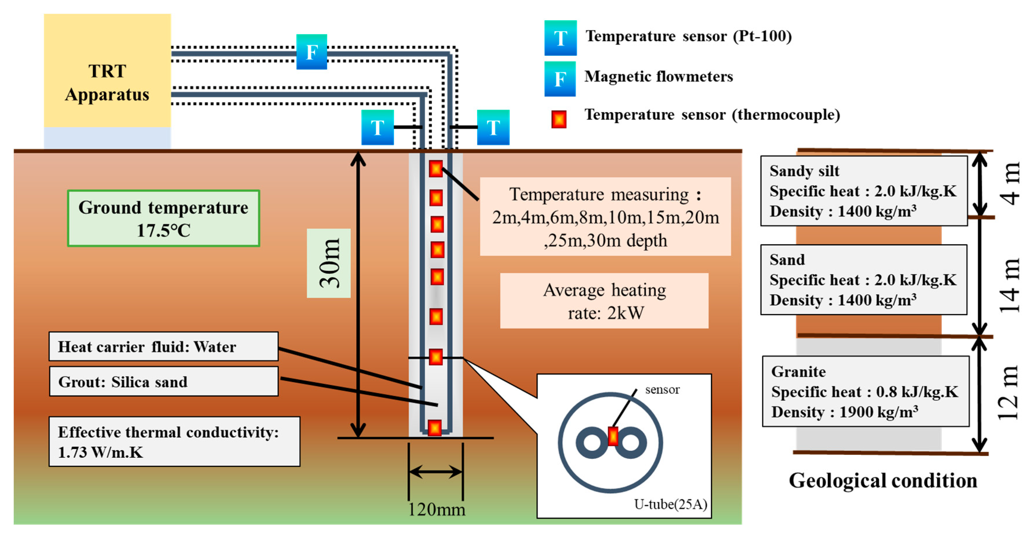
- A TRT was carried out using a GHE with a borehole length of 30 m, and the heat carrier fluid temperature in the GHE and the underground temperature were obtained using measurements. The results were then compared with the results from the simulation. The relative error of the temperature of the heat carrier fluid was 3.3%. This result indicated that the tool can reproduce the measurements with acceptable precision.
- (3)
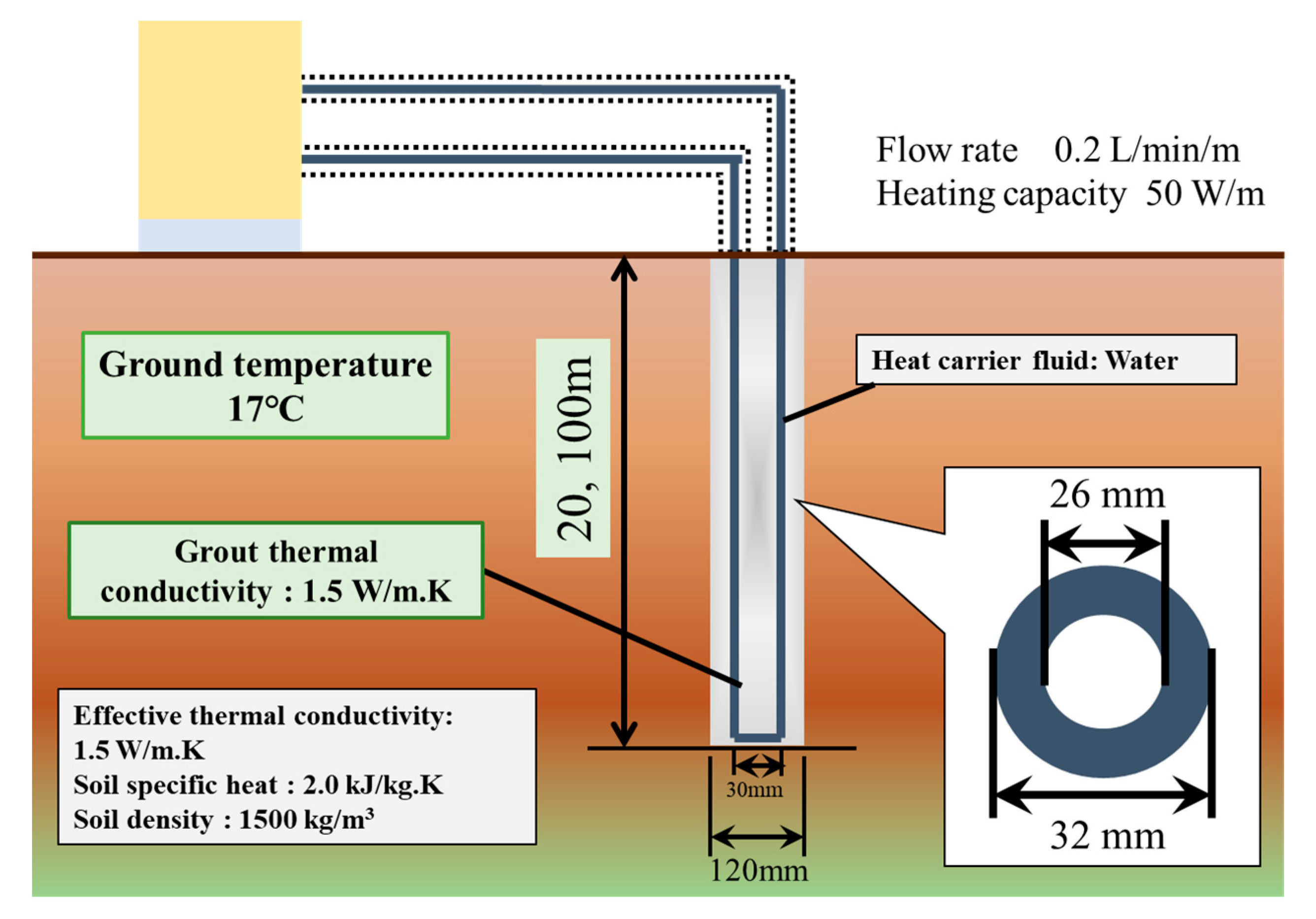
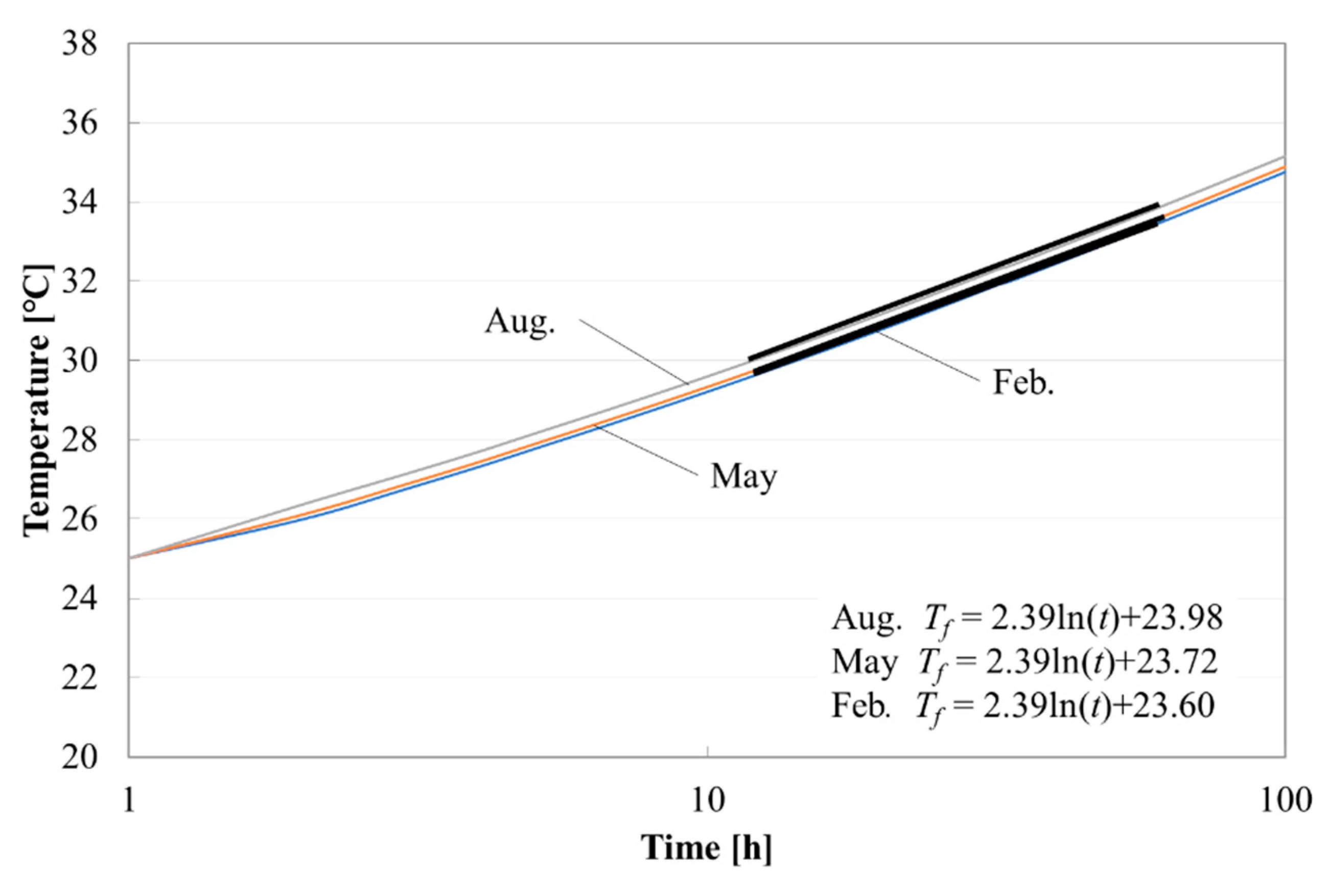
- The influence of the ground surface on the TRT result was investigated using the developed tool. The result showed that the difference of the effective thermal conductivities obtained from TRTs for different seasons is small even when a GHE with a borehole length of 20 m is used.
- (4)
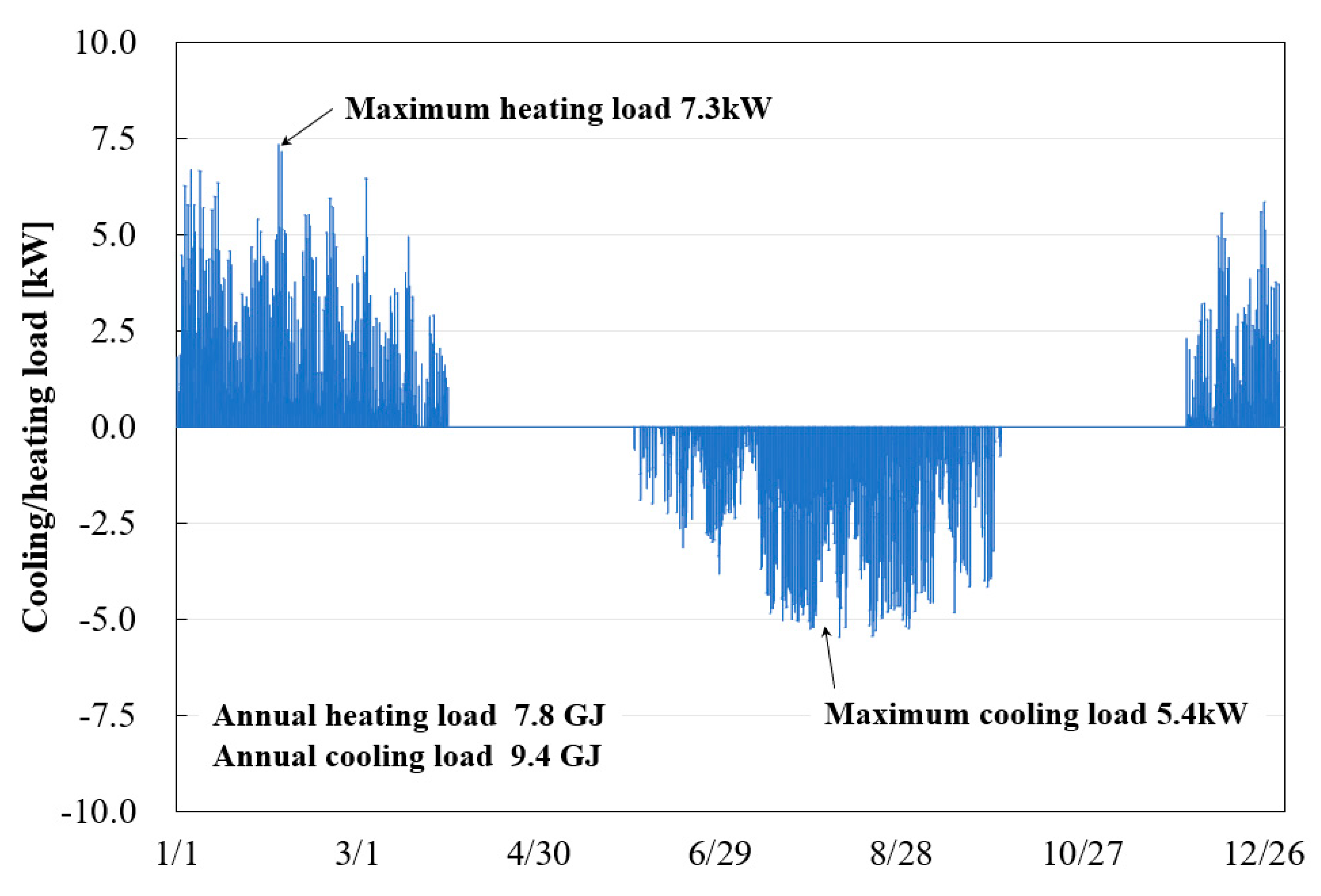
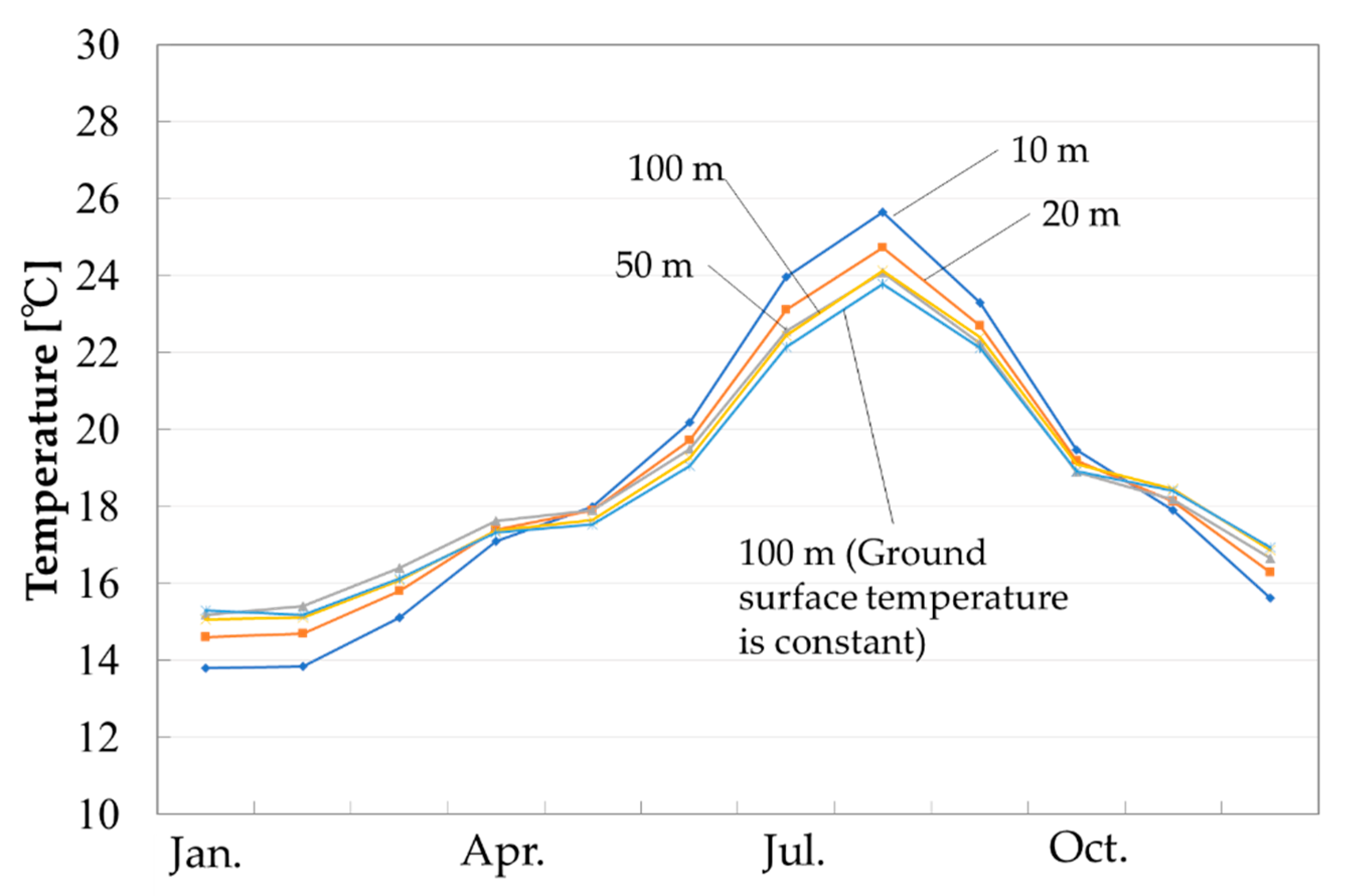
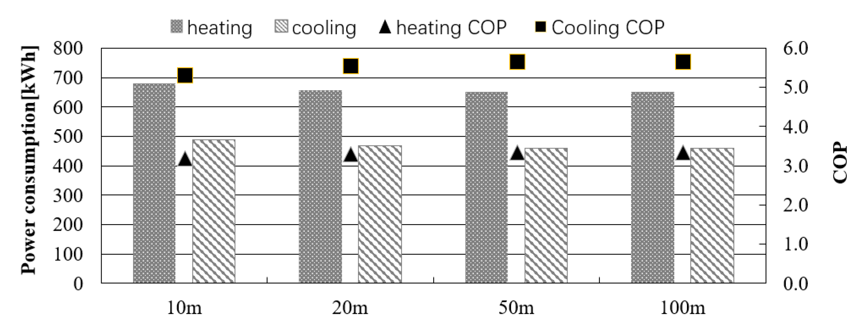
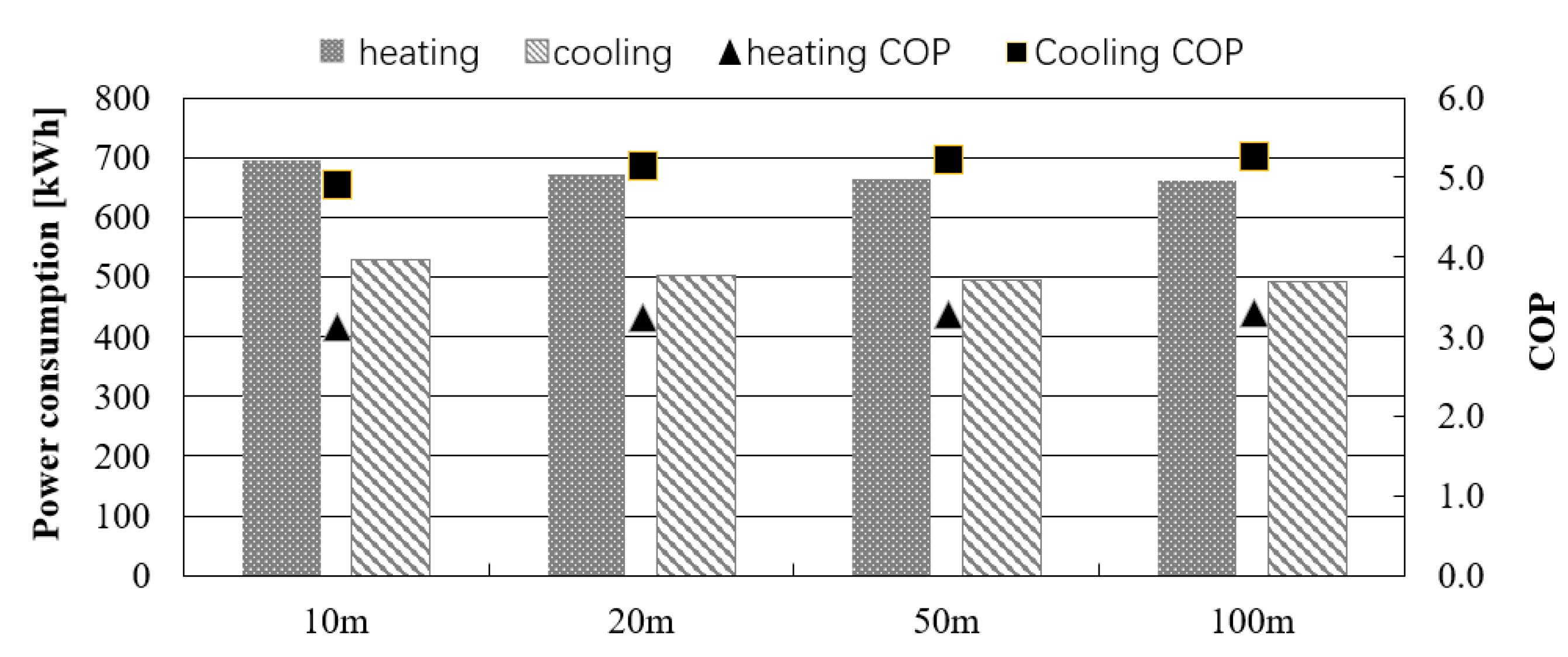
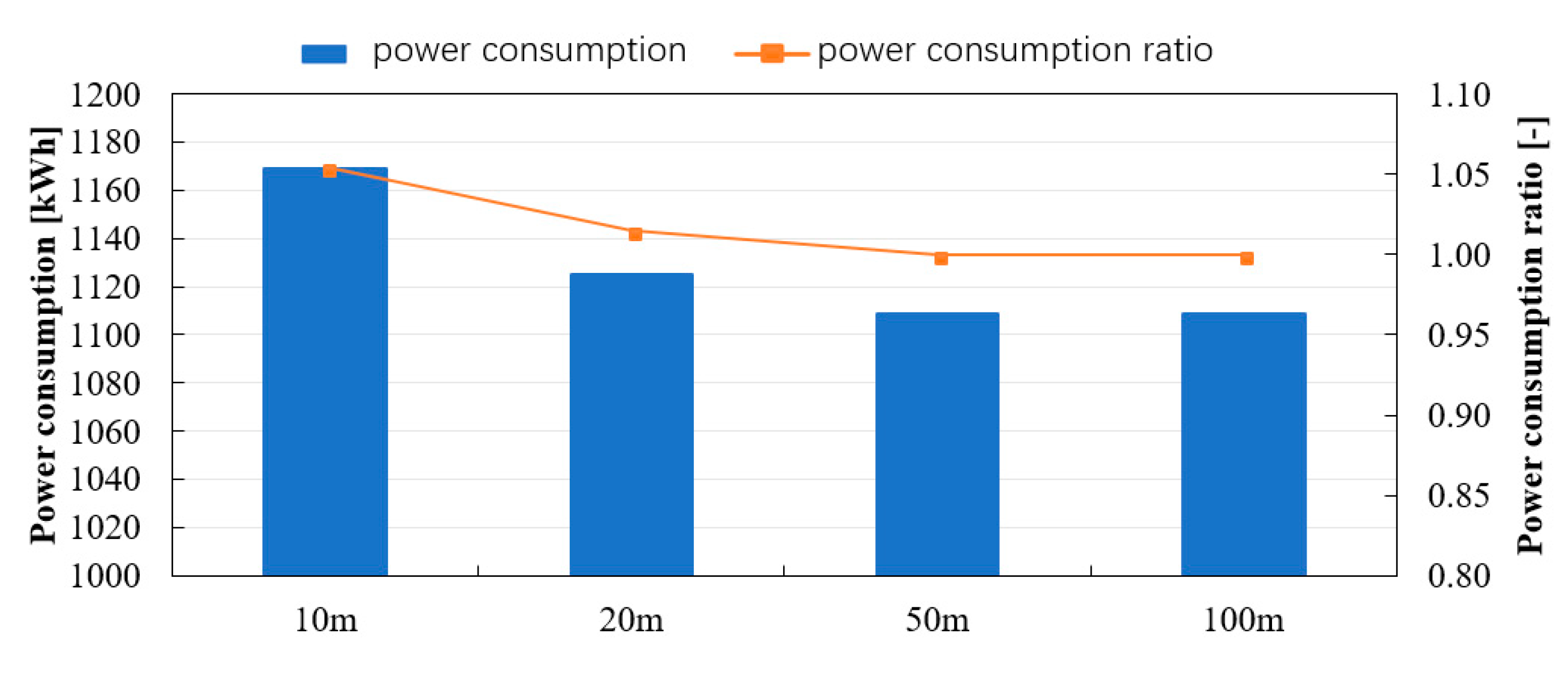
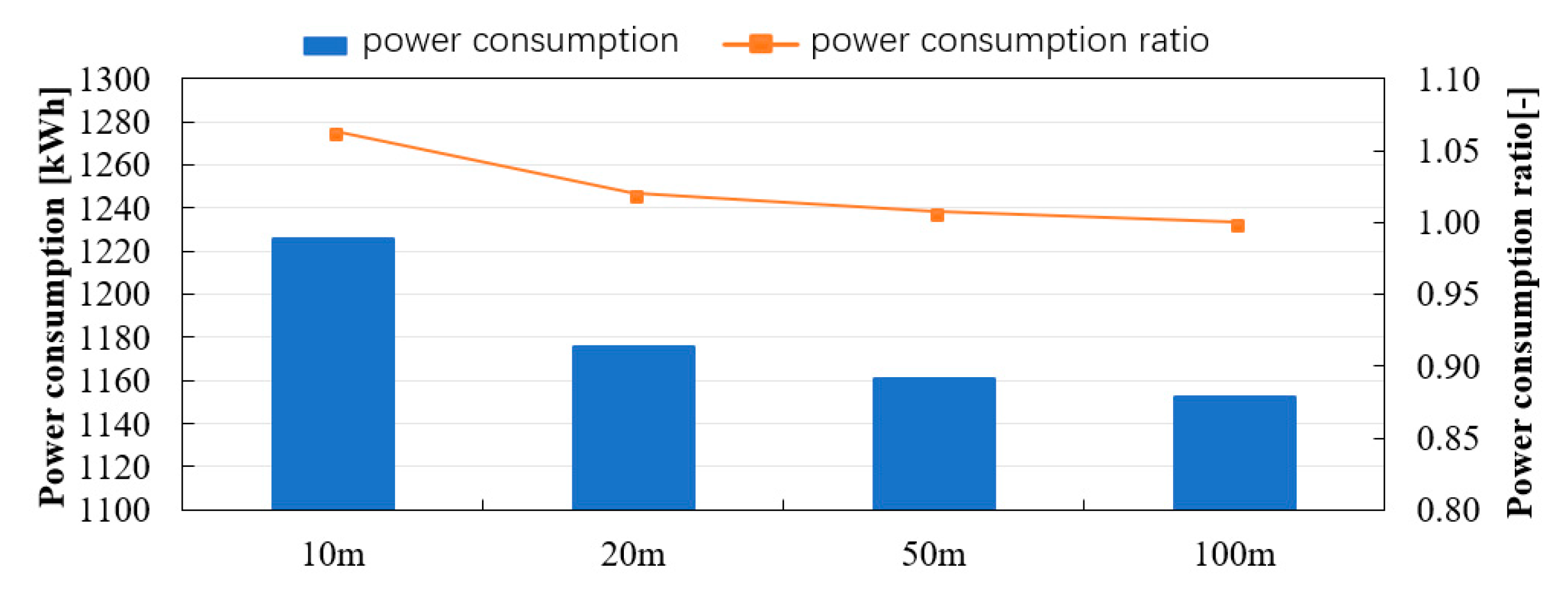
- It was assumed that the GSHP system is installed in a residential house to discuss the influence of the ground surface temperature on the temperature variation of heat carrier fluid in GHEs and the performance of the GSHP system. Comparing the calculation results of GHEs with borehole lengths of 10 m and 100 m under the same total length of GHEs and the same effective thermal conductivity, it was found that the average surface temperature of a GHE with a borehole length of 10 m becomes approximately 2 °C higher than the average surface temperature of a GHE with a borehole length of 100 m in August. Comparing the annual power consumption, a GSHP system using 10 GHEs with the borehole length of 10 m increases the consumption by 5 to 6% compared to a GSHP system using one GHE with the borehole length of 100 m. In the case of the GHE with a borehole length of 20 m, it was found that the increase of annual power consumption was only about 2%.
Author Contributions
Funding
Acknowledgments
Conflicts of Interest
Nomenclature
| A | Area [m2] |
| a | Solar radiation absorption rate [-] |
| C | Correction coefficient [-] |
| c | Specific heat [kJ/kg.K] |
| cp | Specific heat at constant pressure [kJ/kg.K] |
| E | Electric power consumption of heat pump unit [W] |
| G | Flow rate [m3/s] |
| I | Total solar radiation [W/m2] |
| J | Effective radiation [W/m2] |
| K | Overall heat transfer coefficient [W/m2.K] |
| L | Length [m] |
| l | Parameter relating to length [m] |
| N | Number of time step [-] |
| Q | Heating load [W] |
| q | Heat extraction rate [W/m] |
| r | Radius [m] |
| r* | Non-dimensional distance (=r/rp) [-] |
| T | Temperature [°C] |
| T* | Non-dimensional temperature (=λΔT/r/q) [-] |
| t | Time [s] |
| tc | Time starting from July 1 [h] |
| t* | Fourier number (=at/r2) [-] |
| V | Volume [m3] |
| Z | Depth [m] |
| α | Total heat transfer coefficient [W/m2.K] |
| β | Characteristic value [-] |
| ε | Emissivity [-] |
| 𝜆 | Thermal conductivity [W/m.K] |
| 𝜌 | Density [kg/m3] |
| 𝜓 | Equivalent outside air temperature on the ground surface [°C] |
| 𝜔 | Angular velocity (=2π/8760) [-] |
| Subscripts | |
| 1 | Heat pump primary side |
| 1f | Heat carrier fluid in the primary side |
| 1in | Inlet in the primary side |
| 1out | Outlet in the primary side |
| 2 | Heat pump secondary side |
| a | Ambient air |
| C | Temperature response of cylindrical heat sources |
| d | Distance |
| f | Heat carrier fluid (water or antifreeze liquid) |
| I | Solar radiation |
| J | Effective radiation |
| L | Temperature response of line heat source |
| p | Ground heat exchanger |
| pin | Inlet of ground heat exchanger |
| pout | Outlet of ground heat exchanger |
| p-in | Inside of ground heat exchanger |
| p-out | Outside of ground heat exchanger |
| s | Soil |
| s0 | Soil initial |
| s1 | Soil affected by the heat injection/extraction via GHEs |
| s2 | Soil affected by the underground temperature distribution |
| t | Affected by ambient air temperature |
| U-out | U-tube outside |
| -ave | Average |
References
- John, W.L.; Derek, H.F.; Tonya, L.B. Direct Utilization of Geothermal Energy 2010 Worldwide Review. Geothermics 2010, 40, 159–180. [Google Scholar]
- Zarrella, A.; De Carli, M. Heat transfer analysis of short helical borehole heat exchangers. Appl. Energy 2013, 102, 1477–1491. [Google Scholar] [CrossRef]
- Zarrella, A.; Capozza, A.; De Carli, M. Analysis of short helical and double U-tube borehole heat exchangers: A simulation-based comparison. Appl. Energy 2013, 112, 358–370. [Google Scholar] [CrossRef]
- Zarrella, A.; Emmi, G.; De Carli, M. Analysis of operating modes of a ground source heat pump with short helical heat exchangers. Energy Convers. Manag. 2015, 97, 351–361. [Google Scholar] [CrossRef]
- Hamada, Y.; Saitoh, H.; Nakamura, M.; Kubota, H.; Ochifuji, K. Field performance of an energy pile system for space heating. Energy Build. 2007, 39, 517–524. [Google Scholar] [CrossRef]
- Katsura, T.; Nagano, K.; Narita, S.; Takeda, S.; Nakamura, Y.; Okamoto, A. Calculation Algorithm of the Temperatures for Pipe Arrangement of Multiple Ground Heat Exchangers. Appl. Therm. Eng. 2009, 29, 906–919. [Google Scholar] [CrossRef]
- Katsura, T.; Nagano, K.; Sakata, Y.; Wakayama, H. A design and simulation tool for ground source heat pump system using energy piles with large diameter. Int. J. Energy Res. 2019, 43, 1505–1520. [Google Scholar] [CrossRef]
- Fujii, H.; Nishi, K.; Komaniwa, Y.; Chou, N. Numerical modeling of slinky-coil horizontal ground heat exchangers. Geothermics 2012, 41, 55–62. [Google Scholar] [CrossRef]
- Fujii, H.; Yamasaki, S.; Maehara, T.; Ishikami, T.; Chou, N. Numerical simulation and sensitivity study of double-layer Slinky-coil horizontal ground heat exchangers. Geothermics 2013, 47, 61–68. [Google Scholar] [CrossRef]
- Li, H.; Nagano, K.; Lai, Y. A New Model and Solutions for a Spiral Heat Exchanger and Its Experimental Validation. Int. J. Heat Mass Transf. 2012, 55, 4404–4414. [Google Scholar] [CrossRef]
- Li, H.; Nagano, K.; Lai, Y. Heat transfer of a horizontal spiral heat exchanger under groundwater advection. Int. J. Heat Mass Transf. 2012, 55, 6819–6831. [Google Scholar] [CrossRef]
- Xiong, Z.; Fisher, D.E.; Spitler, J.D. Development and validation of a Slinky ground heat exchanger model. Appl. Energy 2015, 141, 57–69. [Google Scholar] [CrossRef]
- Hamada, Y.; Nakamura, M.; Yokoyama, S.; Nagano, K.; Nagasaka, S.; Ochifuji, K. Study on Prediction of Underground Temperature for Utilizing Underground Heat in Snowy Area. Trans. Soc. Heat. Air Condit. Sanit. Eng. Jpn. 1998, 23, 91–100. [Google Scholar]
- Eckert, E.R.G.; Drake, R.M. Analysis of Heat and Mass Transfer; McGraw-Hill Kogakusha. Ltd.: Tokyo, Japan, 1972; pp. 208–214. [Google Scholar]
- Bandos, T.V.; Montero, A.; Fernandez, E.; Santander, J.L.G.; Isidro, J.M.; Pérez, J.; De Córdoba, P.J.F.; Urchueguía, J.F. Finite Line-source Model for Borehole Heat Exchangers Effect of Vertical Temperature Variations. Geothermics 2009, 38, 263–270. [Google Scholar] [CrossRef]
- Nagano, K.; Katsura, T.; Takeda, S. Development of a Design and Performance Prediction Tool for the Ground Source Heat Pump System. Appl. Therm. Eng. 2006, 26, 1578–1592. [Google Scholar] [CrossRef]
- Katsura, T.; Nagano, K.; Takeda, S. Method of Calculation of the Ground Temperature for Multiple Ground Heat Exchangers. Appl. Therm. Eng. 2008, 28, 1995–2004. [Google Scholar] [CrossRef]
- Morchio, S.; Fossa, M. On the ground thermal conductivity estimation with coaxial borehole heat exchangers according to different undisturbed ground temperature profiles. Appl. Therm. Eng. 2020, 173, 115198. [Google Scholar] [CrossRef]
- Nagasaka, S.; Ochifuji, K.; Nagano, K.; Yokoyama, S.; Nakamura, M.; Hamada, Y. An Estimate of the Surface Temperature at a Vertical Ground Pipe by Line Source Theory. Trans. Soc. Heat. Air Condit. Sanit. Eng. Jpn. 1995, 20, 143–152. [Google Scholar]
- Ochifuji, K.; Suzuki, M.; Nakamura, M. Study on Characteristics of Long-Term Underground Heat Storage of Solar Vertical Tube System and Its Application to Heating (1st Report). Trans. Soc. Heat. Air Condit. Sanit. Eng. Jpn. 1985, 10, 95–106. [Google Scholar]
- Architectural Institute of Japan. Extended AMeDAS Meteorological Data 1981–2000; Architectural Institute of Japan: Tokyo, Japan, 2005. [Google Scholar]
- ASHRAE. Ground Source Heat Pumps Design of Geothermal System for Commercial and Institutional Buildings; American Society of Heating, Refrigerating and Air-Conditioning Engineers: Atlanta, GA, USA, 1997. [Google Scholar]
- Fossa, M. Correct design of vertical borehole heat exchanger systems through the improvement of the ASHRAE method. Sci. Technol. Built. Eng. 2017, 23, 1080–1089. [Google Scholar] [CrossRef]
- Katsura, T.; Higashitani, T.; Fang, Y.; Sakata, Y.; Nagano, K.; Akai, H.; Oe, M. A New Simulation Model for Vertical Spiral Ground Heat Exchangers Combining Cylindrical Source Model and Capacity Resistance Model. Energies 2020, 13, 1339. [Google Scholar] [CrossRef] [Green Version]
- BEST-P Building Operation Manual. Available online: http://www.ibec.or.jp/best/program/manual/ (accessed on 20 May 2020).





| GHEX | specification | Borehole U-tube |
| Boundary condition of ground surface | Temperature boundary condition | |
| Number of U-tube | 1 | |
| U-tube interval | 0.03 m | |
| Borehole length and number | 1 × 30 m | |
| Borehole diameter | 0.12 m | |
| U-tube outside diameter | 0.032 m | |
| U-tube inside diameter | 0.026 m | |
| Grout thermal conductivity | 3.6 W/m.K | |
| Soil | Density of soil | 1600 kg/m3 |
| Undisturbed temperature | 17.5 °C | |
| Specific heat capacity | 1.5 kJ/kg.K | |
| Effective thermal conductivity | 1.73 W/m.K | |
| Heat carrier fluid | Type | Water |
| Density | 1000 kg/m3 | |
| Specific heat at constant pressure | 4.187 kJ/kg.K |
| GHE | Specification | Borehole U-tube |
| Boundary condition of ground surface | Temperature boundary condition | |
| Number of U-tube | 1 | |
| U-tube interval | 0.03 m | |
| Borehole length and number | 20 m or 100 m × 1 | |
| Borehole diameter | 0.12 m | |
| U-tube outside diameter | 0.032 m | |
| U-tube inside diameter | 0.026 m | |
| Grout thermal conductivity | 1.5 W/m.K | |
| Density of soil | 1500 kg/m3 | |
| Soil | Undisturbed temperature | 17.0 °C |
| Specific heat capacity | 2.0 kJ/kg.K | |
| Effective thermal conductivity | 1.5 W/m.K | |
| Heat carrier fluid | Type | Water |
| Density | 1000 kg/m3 | |
| Specific heat at constant pressure | 4.187 kJ/kg.K |
| Building | Wooden house | |
| Area | 120 m2 | |
| City | Yahata (Kitakyushu) | |
| Heat loss coefficient (Q-value) | 2.7 W/m2.K | |
| Ventilation | 0.5 times/h | |
| Air conditioning area | 55% | |
| Preset temperature and humidity | Cooling 27 °C, 60% Heating 20 °C, 50% | |
| Heat pump | Water-cooled package air-conditioning heat pump | |
| Rated heating output | 12.5 kW | |
| Rated power consumption for heating | 3.2 kW | |
| Rated cooling output | 11.2 kW | |
| Rated power consumption for cooling | 3.1 kW | |
| Flow rate of circulation pump | 25 L/min | |
| Power consumption of circulation pump | 0.1 kW | |
| GHE | Specification | Borehole U-tube |
| Boundary condition of ground surface | Temperature boundary condition | |
| Number of U-tube | 1 | |
| U-tube interval | 0.03 m | |
| Borehole length | 10 m, 20 m, 50 m, 100 m | |
| Diameter of borehole | 0.12 m | |
| U-tube outside diameter | 0.032 m | |
| U-tube inside diameter | 0.026 m | |
| Grout thermal conductivity | 1.8 W/m.K | |
| Soil | Density of soil | 1600 kg/m3 |
| Undisturbed temperature | 17.8 °C | |
| Specific heat capacity | 1.5 kJ/kg.K | |
| Effective thermal conductivity | 1.5 W/m.K 1.0 W/m.K | |
| Heat carrier fluid | Type | Water |
| Density | 1000 kg/m3 | |
| Specific heat at constant pressure | 4.187 kJ/kg.K | |
© 2020 by the authors. Licensee MDPI, Basel, Switzerland. This article is an open access article distributed under the terms and conditions of the Creative Commons Attribution (CC BY) license (http://creativecommons.org/licenses/by/4.0/).
Share and Cite
Katsura, T.; Sakata, Y.; Ding, L.; Nagano, K. Development of Simulation Tool for Ground Source Heat Pump Systems Influenced by Ground Surface. Energies 2020, 13, 4491. https://doi.org/10.3390/en13174491
Katsura T, Sakata Y, Ding L, Nagano K. Development of Simulation Tool for Ground Source Heat Pump Systems Influenced by Ground Surface. Energies. 2020; 13(17):4491. https://doi.org/10.3390/en13174491
Chicago/Turabian StyleKatsura, Takao, Yoshitaka Sakata, Lan Ding, and Katsunori Nagano. 2020. "Development of Simulation Tool for Ground Source Heat Pump Systems Influenced by Ground Surface" Energies 13, no. 17: 4491. https://doi.org/10.3390/en13174491
APA StyleKatsura, T., Sakata, Y., Ding, L., & Nagano, K. (2020). Development of Simulation Tool for Ground Source Heat Pump Systems Influenced by Ground Surface. Energies, 13(17), 4491. https://doi.org/10.3390/en13174491


