1. Introduction
Low-voltage electrical systems may be subjected to abnormal operating conditions [
1,
2], which can lead to overcurrents with thermal and electromagnetic effects involving inadmissible or intolerable overvoltages for the insulation. For these reasons, anomalous conditions should be limited, and if possible, avoided.
The possibility of electric fires is often underestimated, even if we use countless electrical devices every day. Indeed, in Italy, between 30,000 and 50,000 fires occur every year inside buildings, around 27% of which are of electrical origin, according to the National Fire Department [
3]. In other countries, this percentage is even higher, due to the mass use of electricity for heating and hobs.
Electrical fires account for over 10% of all fires in buildings. Unfortunately, these thousands of fires also claim dozens of victims annually [
4]. Without considering electrostatic discharges and lightning, the main causes of such fires substantially comprise the following:
Overload, which is caused by design errors, non-compliant changes, or the addition of energy-intensive loads. Usually, these lead to premature deterioration of the insulation, and therefore, turn into short circuits.
Connection terminal issues, where the continuous expansion and thermal contraction of materials, vibrations, wear, or the sliding of the connected cables causes a loosening of the contact pressure, which can cause localized overheating, and in some cases, unwanted sparking.
Conductor failures due to the presence of poor quality material, or vibrations and mechanical stress.
Insulation faults, where the rapid degradation or aging of insulation causes the deterioration of the intrinsic characteristics of insulating materials, such as voltage retention.
The loss of insulation between the (normally live) conductors and the earth can cause a fault, which is generally called an earth fault. The main effects of an earth fault current are: (i) earth connections at non-zero voltages, (ii) the occurrence of electric arcs with the subsequent conductor overheating, (iii) the generation of electromagnetic disturbances in telecommunication systems, and (iv) the erosion phenomena of electric earth rods. The current intensity during a fault is mainly due to the specific grounding system.
For this reason, in the United States, it is mandatory to install an AFDD (arc fault detection device) to protect the electrical system and the building. This is an electronic device that measures and analyzes the current waveforms [
5,
6] and interrupts the circuit if it detects the characteristics of an electric arc [
7,
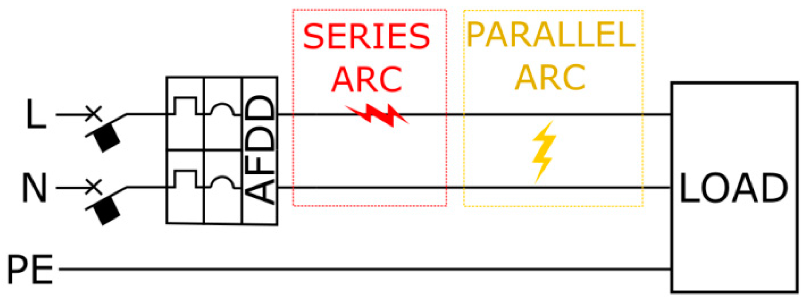
8]. An AFDD provides fire protection against both series and parallel arcs (see
Figure 1). During a series arc fault affecting only one active conductor, the earth leakage current is zero. Therefore, a differential switch cannot detect the fault and the magneto-thermal relay does not trip, as the impedance of the fault arc is added to the load impedance and reduces the current, which thus, remains well below the trip threshold [
9,
10,
11]. For a parallel arc between the phase conductor and the neutral conductor, the series of the impedance of the system and the impedance of the arc itself limit the current. The resulting fault current may be lower than the threshold level of the protection device, as also happens for ground faults (see
Table 1).
A fault initially manifests itself as an arc with a very low current intensity (tens of milliamps), located at a point where the insulation level is lacking. Subsequently, the fault more or less rapidly evolves. If the current is not promptly interrupted by protection, it can involve the other phases, thus giving rise to short circuit conditions [
13].
The two primary standards for AFDD certification are AFCI UL1699 and IEC62606, which require similar arcing tests [
14]. A test and analysis system for the action characteristics of AFDD was presented in [
15]. Further different criteria and test proposals have been presented in [
16].
AFDD is a fairly hot research topic, but the majority of studies have considered arc formation and arc recognition logic.
In this study, a portable system for testing already installed AFDDs was proposed. This system must be light and small in size, and must also have a low cost and provide repeatable and easy-to-read measurements.
In the proposed testing system, the generation of the arcs is performed with surge suppressors.
The surge protective devices (SPDs) are generally adopted to protect electrical systems and equipment from the effects of transient and impulsive surges, such as lightning electromagnetic pulses (LEMP) or switching electromagnetic pulses (SEMP).
When overvoltage phenomena occur, electric arcs are triggered by surge protective devices between a part of the system and the earthing system; with these devices, electrical systems and equipment are protected from surge events because transient voltages and diverting surge currents are limited.
The most intense surges can be originated externally by lightning, or internally by the switching of electrical loads, for example; the internal surges account for 65% of all the transients, and include loads turning on and off, relays and/or breakers operating, heating systems, motors, and office equipment.
In the most basic sense, when a transient voltage occurs in a protected circuit, an SPD limits the transient voltage and diverts the current back to its source or ground. An SPD contains at least one non-linear component that switches from a high- to a low-impedance state.
At normal operating voltages, SPDs are in a high-impedance state and do not affect the system. When a transient voltage occurs in the circuit, the SPD moves into a state of conduction (or low impedance) and diverts the surge current back to its source or ground by limiting or clamping the voltage to a safer level.
After the transient is diverted, the SPD automatically resets back to its high-impedance state (if the diverted current has not damaged the SPD by overheating it).
In
Section 2 of this paper, the characteristics of electric arcs are described, while in
Section 3, the operation of AFDDs is briefly described. The test platform implemented in our research is illustrated in
Section 4. In
Section 5 and
Section 6, the results of the various tests carried out with the proposed platform are shown.
The research presented in this paper is the initial phase of the development of a portable diagnostic system for the verification of electrical systems that use AFDDs for protection against electric arcs. This tool will make buildings safer [
17,
18] by checking the effective operation and intervention times of each AFDD device.
2. The Electric Arc
Electric arcs are phenomena with potentially high energy content, which manifest as a discharge (spark) between two conductive surfaces at different voltages, thus generating local overheating with high temperatures (up to 10,000 °C). This process may be desired—for example, to obtain fusion in the welding process—but it may also be unwanted, as in the case of breakdowns that trigger fires. Once the arc is triggered, a current is established, with consequent heating of the surrounding area, which causes further ionization of the air. Thus, a strongly ionized gas channel is created, in the form of plasma, which behaves like a non-linear conductor that is capable of supporting the electric arc until the destruction of the conductive parts.
Using Joule’s law, the energy developed during an arc fault is:
where
R is the resistance of the entire current path (including the arc impedance),
I is the fault current, and ∆
t is the time interval during which the fault persists.
3. The Arc Fault Detection Device
AFDDs are protective devices that are installed to detect the presence of electric arc faults in power circuits. The first models were developed in the 1980s, mainly for the U.S. market; their use is currently adopted all over the world. The international standard “CEI EN 62,606 (CEI 23-129): General requirements for electric arc fault detection devices” divides them into three types [
19]:
Single AFDD, which is suitable for a series connection with a short circuit protection device.
Single AFDD with an integrated short circuit protection device.
AFDDs that are intended to be assembled on-site with a protective device.
Thermo-magnetic switches (MTSs) are automatic devices capable of withstanding and interrupting all currents, including short circuit currents. In a miniature MTS, the automatic opening of the circuit is determined by the action of two spring devices: one magnetic and one thermal. The first intervenes in the event of currents that exceed the short circuit current threshold, while the second intervenes when the characteristic curve of an overcurrent is exceeded.
The thermal relay consists of two metal foils joined together (a bi-foil) that are characterized by different coefficients of thermal expansion. The heat developed through the Joule effect from an overcurrent causes an increase in the temperature of the bi-foil, with consequent uneven expansion. This deformation is used for sprinting a harpoon that releases a spring that was previously loaded during the manual closing of the circuit breaker, which causes the circuit breaker contacts to open.
The operation of the magnetic relay is based on the force exerted by an electromagnet on a mobile iron core. The mobile core is subjected to two opposing forces: an attractive magnetic force toward the magnetic core and a spring-loaded force, which occurs during the manual closing of the switch. In the event of a short circuit, the electromagnet becomes energized. It overcomes the force of the spring, thus moving an anchor that opens the electrical circuit, to which the switch is connected, within a short time.
MTSs have rated currents up to 125 A, are non-adjustable, and have a tripping characteristic time–current curve, as established by the EN60898-1 (CEI 23-3/1) standard. According to this standard, the time–current characteristic curves can be divided into five classes: B, C, D, K, and Z [
20].
On the other hand, the implementation of an AFDD cannot be carried out only with electromechanical components, such as the briefly described MTS. An AFDD is based on a microprocessor, which analyzes the shape of the current and voltage by recognizing typical arc effects, such as high-frequency disturbances and micro-interruptions of the current when passing through zero. To communicate the type of fault that has been detected to the user, some models use flashing LEDs at different frequencies for a series arc, a parallel arc, overvoltage, overheating, and so on.
The operating principle of an AFDD device is based on the analysis of the current, as described in [
21]. The detection algorithms are divided into direct extraction algorithms (e.g., fractal, integral current, and current variation) and double operation algorithms (e.g., transformation and descriptors) [
22], such as the wavelet transform [
23], the Fourier transform, filter, and correlation. In [
24], the current was decomposed and reconstructed through a wavelet function using a STm32 platform.
A wavelet function has also been used to analyze series arcs in [
25]. The algorithms proposed in [
26] used Kalman filters to confirm the presence of series arc faults.
The device tested was an AFDD with an integrated thermo-magnetic switch, the S-ARC1 M B10 model (produced by ABB), with a 10 A rated current, a 10 kA breaking capacity, and a type B tripping characteristic curve.
The device was designed to be installed on a rail DIN (German Institute of Standardisation) with a footprint of two standard modules. It was equipped with a test button, along with an LED that indicates both the operating status and the type of the occurred fault [
27]. During the test, it was installed inside a resin box and connected to cables with safety 3.5 banana plugs, as shown in
Figure 2.
According to the IEC 62606 standard [
28], the AFDD complies with the series arc regulation if it intervenes within the values indicated in
Table 2 for the respective test current value up to the rated current. The test must be performed at the rated voltage U
r and the DUT(Device Under Test) will conform to the parallel arc standard if the standards in
Table 3 are respected within a period of 0.5 s with fault currents of 75 and 100 A.
The test must be performed by placing a specimen cable of suitable characteristics, either in series or in parallel, which creates the arc fault.
4. Test Platform
For the realization of the test system, a surge arrester was connected downstream of the AFDD device to trigger a controlled electric arc. A resistor was added in series to the arrester, where its impedance was set to limit the current to half the rated value of the circuit-breaker. This was required to avoid the detection of possible overcurrents by the AFDD under test, which was expected to open the circuit only if arc currents were generated.
As the AFDD is sensitive to the distortion of voltage and current waveforms, in terms of the THD (total harmonic distortion), it was necessary to guarantee that the applied voltage was sinusoidal. To achieve this aim, the circuit was powered with an EMC Partner Harcs 1000, which can provide a perfectly sinusoidal voltage with a supplied power up to 4 kW at 230 Vrms. A host PC controlled this apparatus, which could be used to measure the power parameters as a digital wattmeter, as well as to display the supplied voltage and current waveforms.
As the protective device under test could be assimilated into a two-port, where the input and output voltages and current waveforms were monitored.
For the acquisition and processing of the voltage and current waveforms, an ad-hoc data acquisition system was designed. Its elements are described in the following.
4.1. Power Supply
The test circuit was powered using the EMC Partner HAR 1000-1P power system to filter the supply voltage from the grid and to have a sinusoidal voltage for the adoption in the testing of the AFDD. To achieve this aim, the input signal was conditioned using the instrument through a voltage- and current-controlled power amplifier and was configured using the proprietary HARCS software.
To achieve zero distortion and to guarantee a stable test voltage, the amplifier had an internal impedance close to zero.
4.2. Data Acquisition Board
Acquisition signals were sampled using a National Instruments NI6225-USB DAQ board. It has 80 single-ended analog input channels and 40 differential channels with a 16-bit resolution and sampling rates of up to 250 kS/s; it also has two analog output channels and 24 digital output channels. The board transferred information to the PC using a high-speed USB connection.
4.3. The Transducers
For the acquisition of the waveforms of the voltages and currents upstream and downstream of the thermo-magnetic switch, the DAQ was connected to two LA 55-P [
28] current transducers and two LV 25-P [
29] voltage transducers, both utilizing the Hall effect and were connected as shown in
Figure 3.
The LA 55-P guarantees errors of ±0.65% if supplied at ±15 V DC, a linearity error < 0.15%, and a step response time < 1 s @ 90% of the nominal current; the LV 25-P guarantees errors of ±0.8% if supplied at ±15 V DC, a linearity error < 0.2%, and a step response time of 40 s @ 90% of the nominal current.
The LA 55-P frequency bandwidth was 200 kHz, while the LV 25-P frequency bandwidth was 8.75 kHz.
The voltage transducers were connected through the resistance R1 in parallel with the input and output of the AFDD, respectively. The current transducers were connected in series to the input and output circuits of the AFDD.
A further advantage of the use of Hall effect sensors is the galvanic isolation that is created between the test circuit and the data acquisition circuit. The resistance R1 was calculated to provide a current of approximately 10 mA on the measuring circuit at nominal voltage. Instead, between the measurement card and the DAQ card, four Rm resistances of 100 Ω were installed.
4.4. Surge Arrester
The goal of developing a portable testing system that allows for safe and reliable on-site operations meant that we needed to choose discrete components to create repeatable and cheap tests without having to perform a compliance test of the AFDD, which requires laboratory instrumentation, according to [
30]. Devices that can induce a series arc in the range of 15–30 s after the start of the test were considered suitable for the proposed on-site testing system.
A set of two-electrode 2049-xx-BLF arresters from Bourns were used, which were connected in series to a resistor of appropriate value to generate a reproducible electric arc. These are usually used against transient and impulse overvoltages, such as those caused by lightning or maneuvers on the system. In these cases, they trigger an electric arc between a part of the system and the earth by limiting the voltage on the device to be protected.
The SPDs chosen use gas discharge tube technology, and therefore, can be considered as high-speed switches with conductance properties that change very quickly from an open circuit to almost a short circuit in the event of a fault. They were designed to withstand many impulses without the destruction or loss of their initial characteristics (even after 500 operations) [
31].
The main parameters of these devices are the discharge current and the spark overvoltage; this is the discharge voltage in the presence of a rapid front dV/dt and increases as the rapidity of the voltage front increases. To create the arc and to trigger the AFDD device under test, the parameters were chosen to be DC sparking overvoltages equal to 75, 90, 120, 145, 250, and 300 V in the presence of a steep front of 100 V/μs and with an impulse spark over less than 500 V for a steep front of 100 V/μs.
5. Experimental Tests
The first test was carried out by powering the circuit with a purely sinusoidal voltage of 230 V. The intervention of the AFDD with different models of surge arresters was monitored. It was noted that the tripping time of the AFDD was linked to the sparking overvoltage values of the SPD. From the results obtained, the subsequent measurements were carried out using the 2049-09 surge arrester described above with a sparking overvoltage of 90 V, as this triggered an arc with a characteristic voltage, current, and THD values that caused the protection circuit-breaker to open quickly enough.
It should be noted that the waveforms of the circuit under examination can be considered to be similar to the waveform of the voltage at the ends of the load in a voltage regulator circuit with a TRIAC (TRIode for Alternating Curren). We note that the angle between the zero-crossing and the ignition angle of the TRIAC (in this case, the arc ignition angle) increased by changing the surge arrester with an increasing voltage spark.
In the last test, an autotransformer was inserted after the protection device to verify the correct operation of the AFDD by varying the applied voltage.
5.1. Test 1 (Sparking Overvoltage = 75 V)
When the circuit-breaker closed, a series electric arc was generated, as the voltage exceeded the scintillation voltage, which persisted until the SPD fused or the device opened.
The first test was carried out by inserting a Bourns 2049-07 SPD with a sparking overvoltage of 75 V and a series resistance of 47 Ω. In this case, the arc caused a failure, namely, by burning itself via the Joule effect without the intervention of the AFDD. The arc persisted until the fault turned into a short circuit.
Figure 4 shows the instant at which the arc was formed, while
Figure 5 shows the instant at which the arc turned into a short circuit.
Figure 6 shows the magnification of the positive half-wave, in which the distortion of the current and voltage can be clearly seen.
5.2. Test 2 (Sparking Overvoltage = 90 V)
Using the Bourns 2049-09 surge arrester with a sparking voltage of 90 V, the protection device tripped and stopped the fault in 32 s.
In
Figure 7, the start time of the electric arc is shown. This lasted up to the point shown in
Figure 8. In
Figure 9, a half-period with jagged waveforms of the head and the current is shown.
5.3. Test 3 (Sparking Overvoltage = 120 V)
Using the Bourns 2049-12 surge arrester with a 120 V sparking voltage, the AFDD intervened, eliminating the fault in 32 s.
Figure 10 shows the waveforms when the circuit was closed and
Figure 11 shows the circuit that was opened by the AFDD. In the detail of
Figure 12, we can see that the waveforms were more regular than in the previous case.
5.4. Test 4 (Sparking Overvoltage = 140 V)
This test was carried out using the 2049-14 surge arrester, where the protection device intervened, as in the two previous cases. The graphs of the currents and voltages acquired at the instant of arc formation and during the opening of the AFDD are shown in
Figure 13 and
Figure 14, respectively. A section of the characteristic waveform of the arc is shown in
Figure 15.
5.5. Test 5 (Sparking Overvoltage = 230 V)
The instant when the arc was formed and the instant the circuit was opened by the AFDD, using the Bourns 2049-23 surge arrester (sparking overvoltage 230 V), are visible in
Figure 16 and
Figure 17, respectively. The deformation of the arc is shown in
Figure 18. The AFDD opened the system after 61 s.
5.6. Test 6 (Sparking Overvoltage = 250 V)
A 2049-25 SPD, with a sparking voltage of 250 V, was used. When the circuit-breaker closed, an arc was generated, but after a certain time, the arc extinguished itself and the circuit opened, making the test null. Therefore, this surge suppressor was not suitable for the test in question.
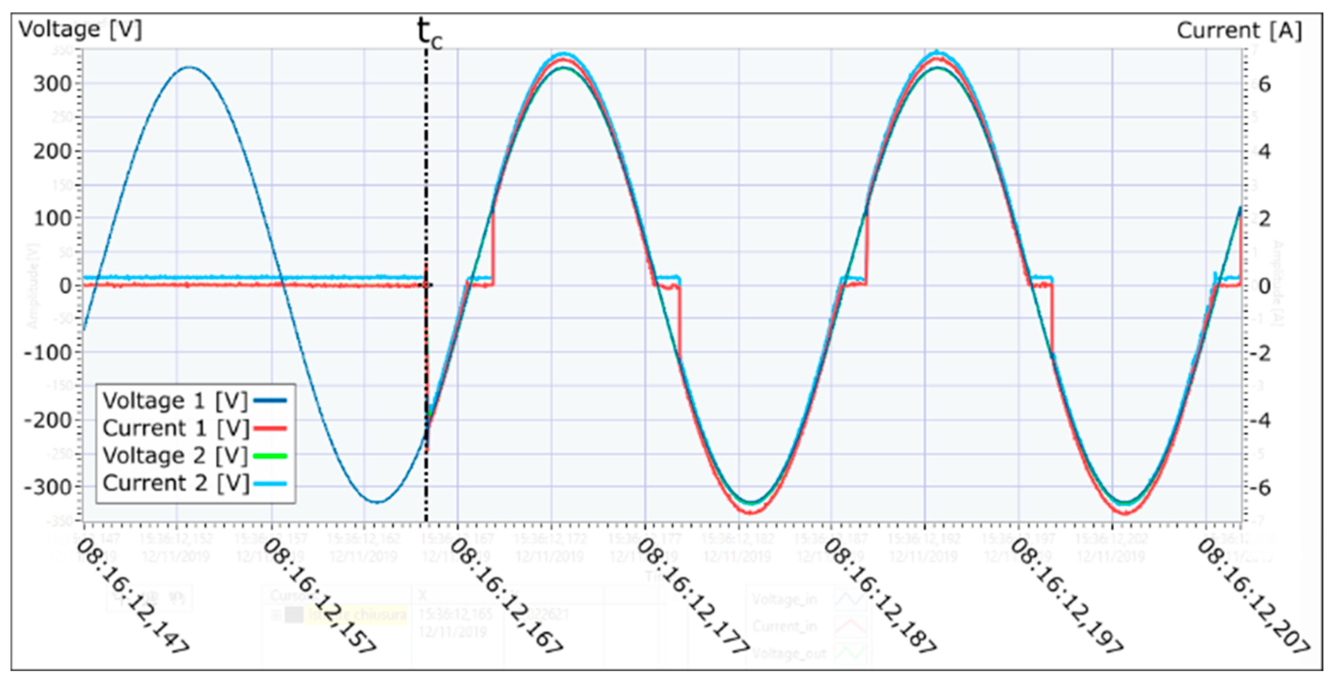
In
Figure 19, the instant of the circuit closing and the beginning of the electric arc is shown, as signified with the marker
tc.
Figure 20 shows that after the marker
te, the current went to zero; therefore, the current suppressor opened the circuit before the intervention of the AFDD.
Figure 21 shows that just before the arrester opened the circuit by interrupting the arc, it circulated the current only in the positive half-waves.
5.7. Test 7 (Sparking Overvoltage = 300 V)
When using the Bourns 2049-30 surge arrester with a sparking voltage of 300 V, the AFDD intervened. The instant at which the arc was formed and the instant the circuit opened are visible in
Figure 22 and
Figure 23, respectively. The deformation of the arc over a complete period is shown in
Figure 24.
6. Results
The duration of the electrical fault series is equal to the time that elapses between the closing of the circuit-breaker and its reopening (Equation (2)) or the evolution in the short circuit fault (Equation (3)):
The initial calculation instants
tc and final
te are shown in the respective figures with black dashed lines. The intervention times in the various tests were calculated, as shown in
Table 4.
After the first tests with the various surge arresters, we chose to carry out repetitive measurements using the Bourns 2049-09 surge arrester, as it generated a series arc that caused the AFDD to intervene quickly compared to the other models. Ten tests were carried out, where the intervention times of the protection device are shown in
Table 5.
The tripping time of the AFDD was in the range of 16–32 s, with an average time of 18.8 s. The Bourns 2049-09 surge arrester behaved in agreement with the abovementioned goal of obtaining series arcs in the range of 15–30 s after the start of each test.
By analyzing the waveform shown above, it was clear that the AFDDs did not operate immediately when the waveform of the current deformed, taking on the characteristics similar to that of a circuit with a phase-shifter, for example, but only when the ionization of the gas inside the surge arrester and the heat generated by it created the phenomenon of fast current spikes. Such behavior can be successfully adopted to verify the correct functioning of the AFDD relative to untimely trips caused by non-linear circuits.
7. Conclusions
The use of an AFDD with integrated overload and short circuit protection allows for installing serious and reliable protection in a short time, which highly improves the safety of electrical installation and prevents serious damage to buildings.
The test circuit used in this study was implemented using a combination of surge arresters with a limiting resistor. The waveforms of the electric arc initially described trended similarly to a rectifier bridge. Then, the waveforms began to deform until the deformed current caused the device to trip.
From the graphs, we can see that the arc created a purely resistive circuit; in fact, the voltage and current were in phase.
After further tests were carried out, it was found that there may have been a test failure with a percentage of 5%; this was due to the SPD being damaged, causing a premature short circuit or making it unable to trigger the arc, and therefore, the intervention of the device did not occur. Therefore, in these cases, it is advisable to repeat a new test using a new surge arrester.
The proposed system can be used by electricians to perform repetitive tests on the installed devices to determine the correct operations and intervention times. The intervention times will not be the characteristic times of the IEC 62606 [
30] standards, but instead, will be the times obtained from the test described above on new samples.
In fact, all current standards, even if they are the result of lengthy development, cannot cover all the aspects necessary to characterize the intervention of AFDDs at present [
32], and for the existing tests, different circuits are needed for each test to be carried out [
14].
The implementation of the algorithm in a built-in electronic board with interchangeable surge arresters will be considered for further development of the system.


 ,
, 


