Abstract
This study proposes a classical control algorithm for solving the transcendental set of equations for the unequal DC sources of five-level multilevel inverters (MLIs). Such sources can be generated from renewable energy sources. Two DC sources with different values are used to produce an output voltage with five levels. Then, a set of two transcendental equations is formulated with two targeted functions to control the fundamental component and cancel the stipulated single harmonic order. The proposed solution uses a simple classical proportional control with two loops to generate two switching angles. The first switching angle is assigned with an initial value, whereas the second one is calculated from the inner loop. The outer loop is used to cancel the specified harmonic by sending the error signal to the proposed proportional control that tunes the switching angles. The proposed algorithm is easy, fast, and accurate, and has a wide-range solution in terms of modulation index (
) and input DC source ratio (). The proposed algorithm is tested for a wide range of
and
to verify its feasibility. Moreover, several simulation and laboratory tests are presented to further validate the applicability of the proposed approach.
1. Introduction
Multilevel inverters (MLIs) [1,2,3,4,5,6,7,8] have attracted increasing attention from researchers and industrial sectors due to their excellent performances compared with conventional two-level topologies. MLIs generate a staircase waveform that is close to sinusoidal voltages. In terms of suitable modulation indexes, MLIs can reduce the total harmonic distortion (THD) to extremely low values. In addition, MLIs can operate either at high or low switching frequency. In the case of low switching frequency, MLIs have high efficiency since the power switches operate at low switching frequency; this condition results in low switching losses, low switching stresses, and low electromagnetic interference (EMI). MLIs are also utilized in high-power applications, such as industries, large-scale renewable energy systems, and transportations that use medium-voltage switches [9].
MLIs are divided into three main categories based on their input DC sources: symmetric, asymmetric, and hybrid. Symmetric MLIs have equal values of DC input sources, whereas asymmetric ones have DC input sources with unequal specific ratios. The common DC source ratios are two or three. The third category is introduced to represent MLIs with mixed input DC source ratios. These inverters obtain the maximum number of voltage levels by using the minimum amount of input DC sources and switches [10]. Many common approaches and control algorithms, such as pulse width modulation and space vector modulation, are applied to the MLI categories depending on the applications and requirements of the system [1,2,3,4,5,6,7,8].
As previously mentioned, MLIs can be operated at either high or low switching frequency operation [6,7,8]. The selective harmonic elimination (SHE) method can be used when operating MLIs at low switching frequency. With proper modulation, several low-order harmonics can be selected and removed to improve the output voltage of the MLIs in such case. The implementation of the SHE control algorithm is based on the formulation of harmonic equations, which involves the generation of a set of nonlinear transcendental equations to meet the required objective functions. Many studies attempted to solve this set of transcendental equations by using several approaches, including theory of symmetric polynomials, Newton–Raphson technique, artificial neural network, and genetic algorithms (GA) [11,12,13,14,15,16,17]. These techniques typically adopt offline computations to find the solution of harmonic equations and determine the switching angles. The offline method is simple, and the solutions are precalculated. However, this approach requires a lookup table to store the solutions of the switching angles and generate the control signals for the power switches. In addition, the accuracy is based on the number of data stored.
On the other hand, real-time solution is adopted to track modulation index changes [17,18,19,20,21,22,23,24,25]. These proposed techniques will be discussed in detail, based on symmetrical/asymmetrical DC sources MLI and higher/lower order harmonic eliminations. In [17,18,19,20], real-time SHE solution methods for symmetric MLIs are proposed. In [17], a real-time implementation of selective harmonic elimination pulse width modulation (SHEPWM) using a generalized Hopfield neural network (GHNN) is applied to a single phase with single source DC inverter. The method can solve the higher order of harmonic equations for only a symmetric MLI inverter. In [18], a simple analytical closed-form solution was introduced and validated based on the cosine term identities for multiple angles. The nonlinear transcendental set of equations is transformed into a second-order equation with well-known simple solutions. The proposed solution is fast, accurate, and valid for a wide modulation index (MI) range, but it is limited only for MLIs with symmetrical DC sources. In [19], the formulated harmonic transcendental set of equations is solved in real time using both the cosine term identities for multiple angles and the classical proportional integral (PI) control. There are two loops; the internal loop is adopted for the cosine term identities for multiple angles while the outer loop is adopted for employing the classical PI control to generate the final values of the switching angles. The method is also limited for symmetrical DC sources MLI. In [20], the transcendental nonlinear set of equations is converted to a control system with a lookup table, integral controllers, and a decoupling controller to converge the system to zero error steady state. In this technique, the harmonic spectrum is extracted from the output voltage without the need for applying an FFT algorithm. The results indicated that accurate switching angle control and a fast response can be obtained, and the technique can be used with various symmetrical MLIs applications.
A generalized technique is proposed in [21] to be real-time implemented for both symmetrical and asymmetrical MLIs applications. The formulated nonlinear harmonic transcendental set of equations is transformed to a set of linear equations that can be solved mathematically to generate the required switching angles. The proposed technique is simple, accurate, and fast with a contentious wide range for MI. It can operate at any required levels’ number (even or odd) for the MLIs. The proposed control can control the fundamental component and remove higher orders of harmonics, but the proposed technique fails for unequal DC sources MLI. The results indicated the agreement between the simulation and experimental results.
In renewable energy systems, photovoltaic panels generate variable DC sources based on environmental conditions [22,23]. This phenomenon causes mismatches among their DC sources. Given that these DC sources are typically unequal, different control algorithms should be applied [24,25,26], which are explained in the following paragraphs. In [24], an artificial neural network (ANN)-based algorithm was introduced to calculate switching angles in real time for unequal DC sources. In ANN, the system is trained offline using many data points, and then it can respond in real time. The ANN can guarantee a fast response due to decreasing of time computation, but the output angles returned by the ANN may not provide a satisfactory result, or harmonic elimination, at some points as it generalizes. In [25], an analytical solution based on the cosine term identities for multiple angles was proposed for MLIs with asymmetrical DC sources. The nonlinear transcendental set of equations is transformed into a third-order equation with well-known solutions. The proposed solution is utilized for controlling the fundamental component and removing the third harmonic component. However, this technique is limited only to both actions and fails to solve the set of equations if another harmonic order, such as the fifth or seventh harmonic, is required to be eliminated. In [26], a middle-level selective harmonic elimination pulse–amplitude modulation (SHE–PAM) technique is presented to solve the harmonic equations for single phase MLIs using unequal DC sources. In this method, the switching angles are first assumed as (). The proposed technique used to determine the switching angle and synthesize the reverence voltage of variable DC sources that is connected to MLI. Due to the difficulties in solving high order nonlinear transcendental equations, then the utilization of SHE in some applications is limited in real time.
Therefore, the main contributions of the current work are summarized as follows:
- ⚬
- Real-time operation;
- ⚬
- Operates for symmetrical/asymmetric and unequal DC input sources;
- ⚬
- Its capability for higher-order harmonic elimination;
- ⚬
- Continuous wide ranges for both modulation index and x;
- ⚬
- No special required predetermined value for input/output or angles.
Therefore, this study proposes a new method for calculating the switching angles of MLIs with symmetrical, asymmetrical, and unequal DC sources by using the simple classical proportional control algorithm. The proposed method is fast, highly accurate, and valid for a wide range of and input DC source ratio x and provides online voltage control. The remainder of this paper is organized as follows. Section 2 provides a detailed explanation of the proposed procedure, including the assumptions, equation development, variables, and procedure analyses. Section 3 presents the simulation and laboratory results of the suggested case studies to verify and validate the performance of the proposed technique. Section 4 discusses the relationship among important variables to clarify the proposed concept. Section 5 provides the summary and conclusion. A low prototype is built and tested for validation.
2. Proposed System Model
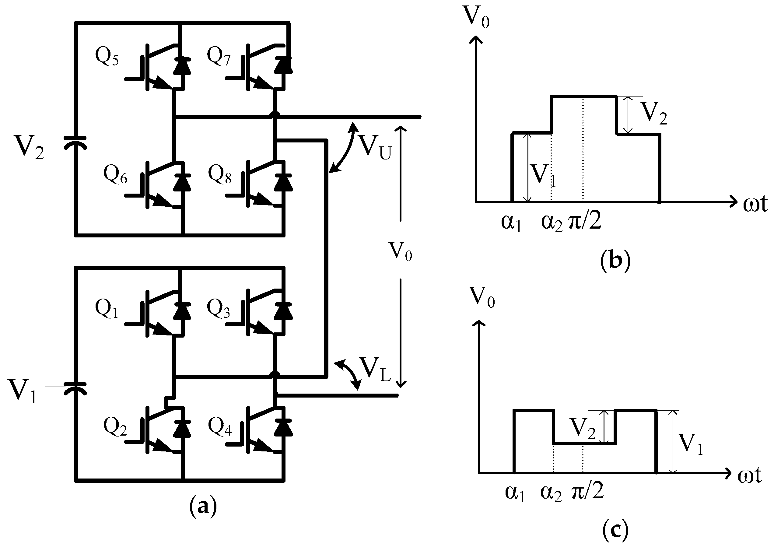
Figure 1a shows a single-phase five-level cascaded inverter with two DC input sources and , where . The waveform of the output voltage (in the positive half cycle) for two switching angles and , where , is presented in Figure 1b. has five levels, namely, . The Fourier series of the staircase waveforms shown in Figure 1b is given in Equation (1). If or is negative, their actual values are their absolute values. Moreover, if and , is expressed as (Figure 1c). In this case, the inverter still generates five levels, but the output voltage waveforms become . The Fourier series of the staircase waveforms shown in Figure 1c is defined in Equation (2).
where is the modulation index, is the fundamental component, is the normalized fundamental amplitude (), and .
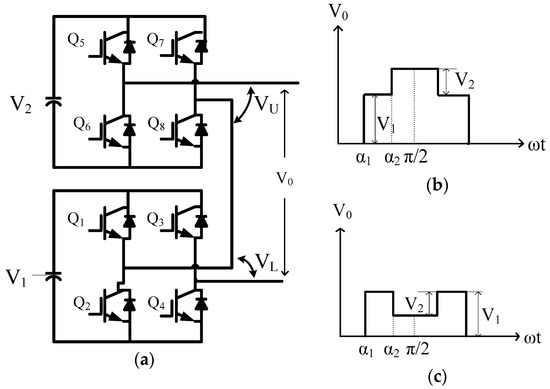
Figure 1.
(a) Unequal DC sources of the cascaded single-phase five-level inverter and output waveforms when (b)
and (c) and ().
The proposed solution controls the fundamental component and removes one of the harmonics (third, fifth, seventh, …). Therefore, two equations are generated from Equation (1) for h1 and the harmonic to be canceled (hn; with order third, fifth, seventh, …).
Equations (4) and (5) can be rewritten using Equations (1) and (3) as
Equation (6) is then modified to
The proposed solution can be summarized in the following steps:
Step1. is assigned with an initial value (), and is calculated from Equation (7) as
Step 2. The value obtained for is substituted into Equation (8) to calculate the fed to the controller and updates the value of as
Step 3. If and , and .
Step 4. and are sorted to satisfy the inequality .
Step 5. If , the output voltage waveform is similar to that presented in Figure 1b.
Step 6. If , , and the output voltage waveform is similar to that presented in Figure 1c.
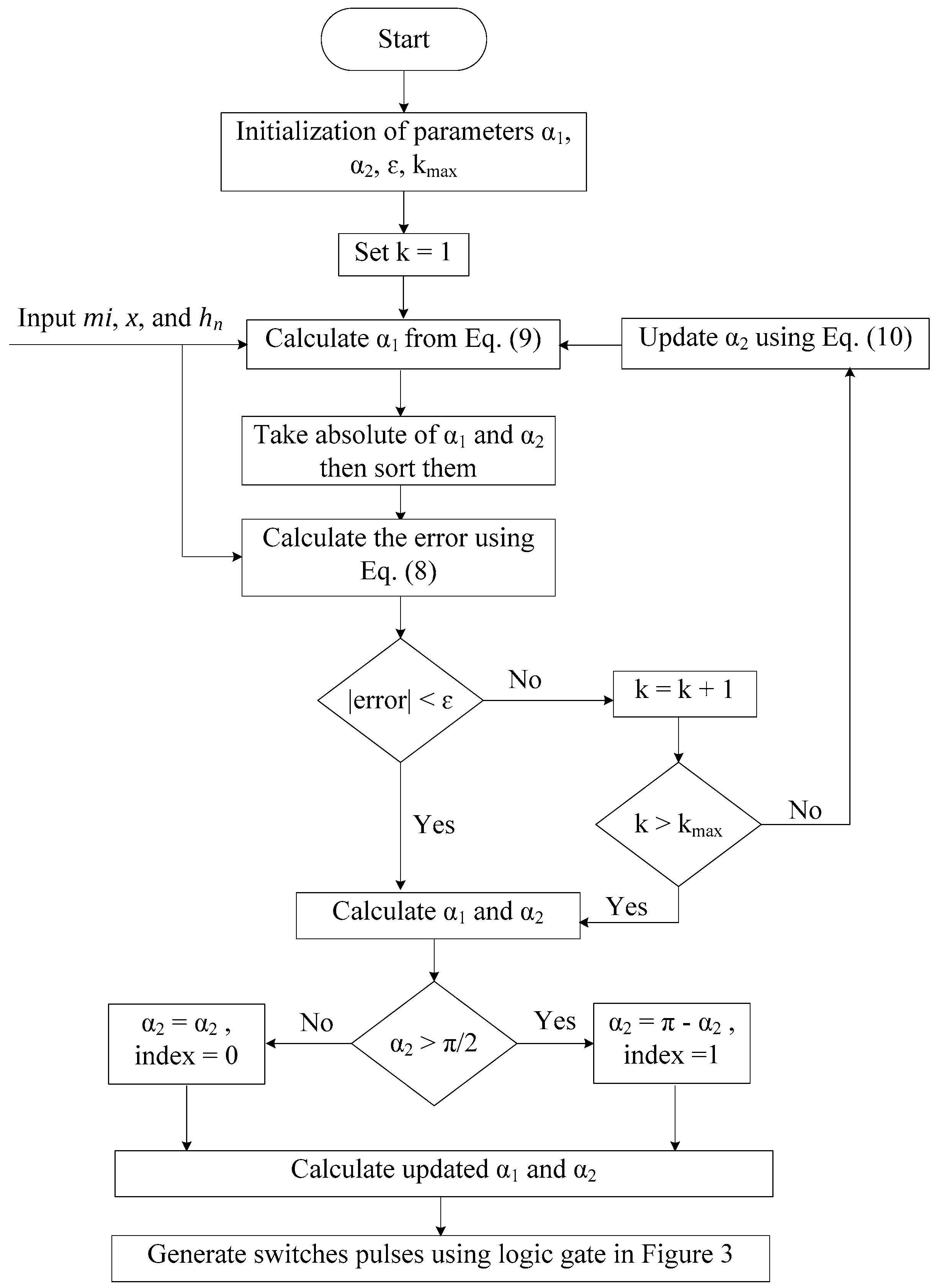
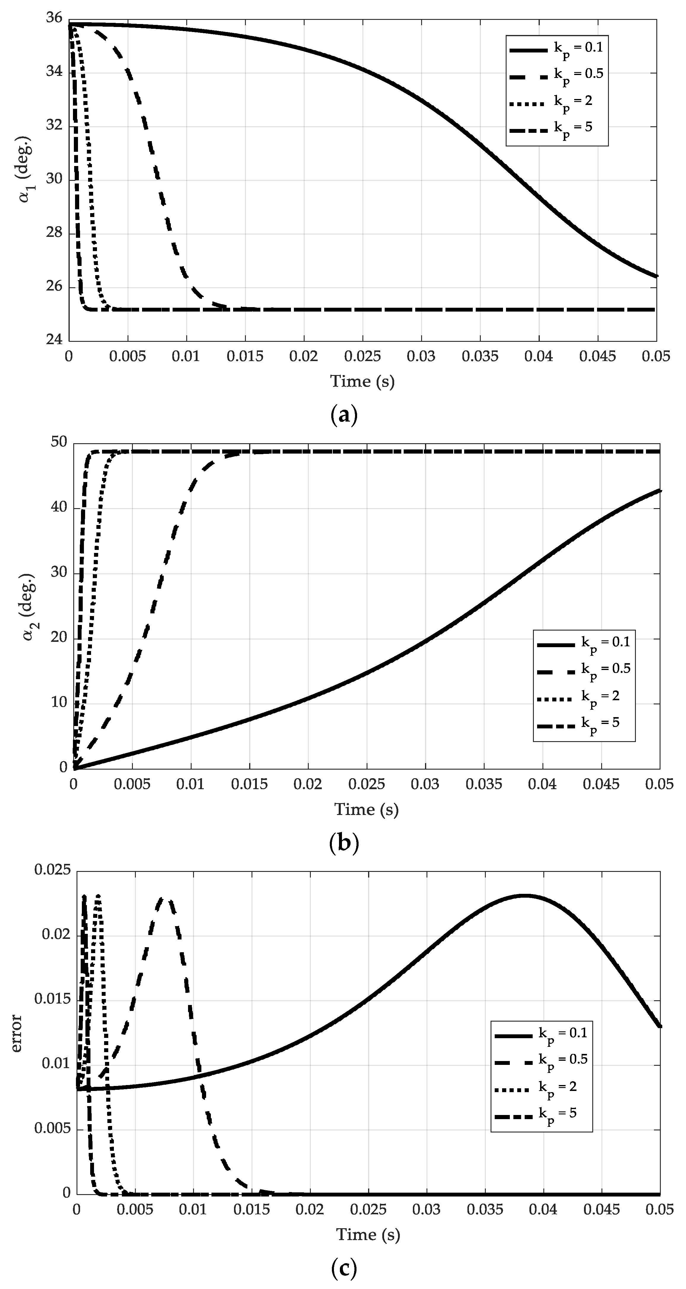
Figure 2 depicts the sequence for implementing the proposed technique. The flow chart has a single and simple iteration loop. The controller used is the proportional controller, which is the simplest controller with only a single parameter (). The gain is increased slowly until an acceptable performance is reached. Figure 3 shows the effect of changing on the switching angles , , and error. It has been found that the system reaches a steady state at = 2 with a raise time approximately equals 2.5 ms, which represents 12.5% of the 50 Hz fundamental output voltage waveform cycle. At = 5, the system reaches a steady state with raise time approximately equaling 1 ms, which represents 5% of the 50 Hz fundamental output voltage waveform cycle. Therefore, the designed range is chosen as = 2 to 5. This value of results in a rapid iteration with a very accurate solution.
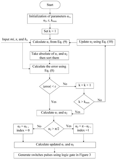
Figure 2.
Flow chart of the proposed solution.
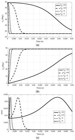
Figure 3.
The effect of the kp changes on (a) switching angle , (b) switching angle , and (c) error signal.
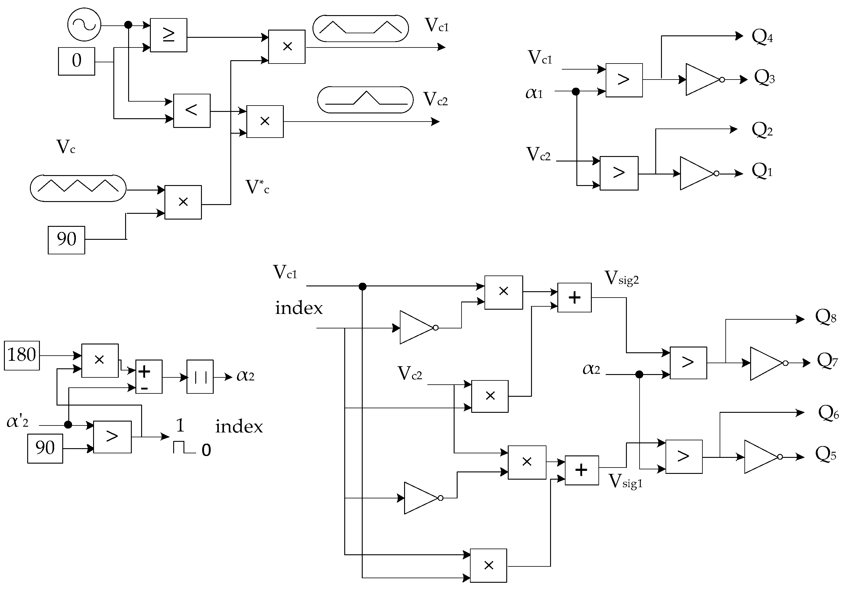
Figure 4 shows the proposed control technique. Logic and carrier signals are used to generate eight switching signals for the MLI system. Figure 4 comprehensively illustrates the last step in the flow chart shown in Figure 2. The carrier (Vc) and AC signals have unity amplitudes with frequencies that are equal to that of the output voltage waveform. Vc is multiplied by 90; thus, the generated carrier (V*c) has an amplitude that ranges from 0 to 90, which is the range of the actual switching angle solutions. The carrier V*c is separated into subcarriers Vc1 and Vc2, which represent the positive and negative half waveform cycles, respectively. Both subcarriers are compared with to generate the switching signals of the lower MLI cells (Q1–Q4). The index has a digital number of 1 or 0. When index = 0, is within the accepted range (0°–90°), and no modification is required. When index = 1, is outside the accepted range (90°–180°), and thus is subtracted from 180° to reduce it to the accepted range. Hence, is modified to . The two index values, Vc1 and Vc2, and are used to generate the switching signals for the upper MLI cells (Q5–Q8). Equations (11)–(14) are used to calculate the switch signal pulses as follows:
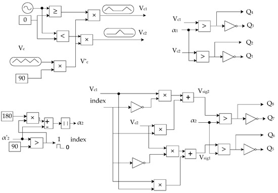
Figure 4.
Logic for the gate pulse generation of the proposed control technique.
3. Simulation and Experimental Results
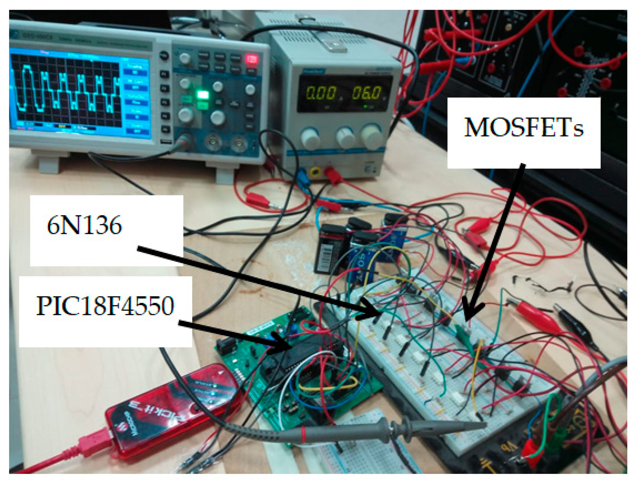
Several case studies were used for simulation and experiments to verify the validity of the proposed method. The system parameters include the input DC voltages (), x (), MI, and . The proposed system is experimentally evaluated using the same simulation test parameters to confirm its effectiveness. The setup of the system is presented in Figure 5. MOSFETs (IRF740) and gate drives includes (6N136) are used as power switches and isolation elements, respectively. The microcontroller PIC18F4550 is used to perform the proposed algorithm and generate the control signal of the switches. MikroC PRO PIC and MPLAB IDE packages are used to write the codes and program the microcontroller, respectively.
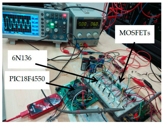
Figure 5.
Experimental setup of the proposed system.
Case Study I:
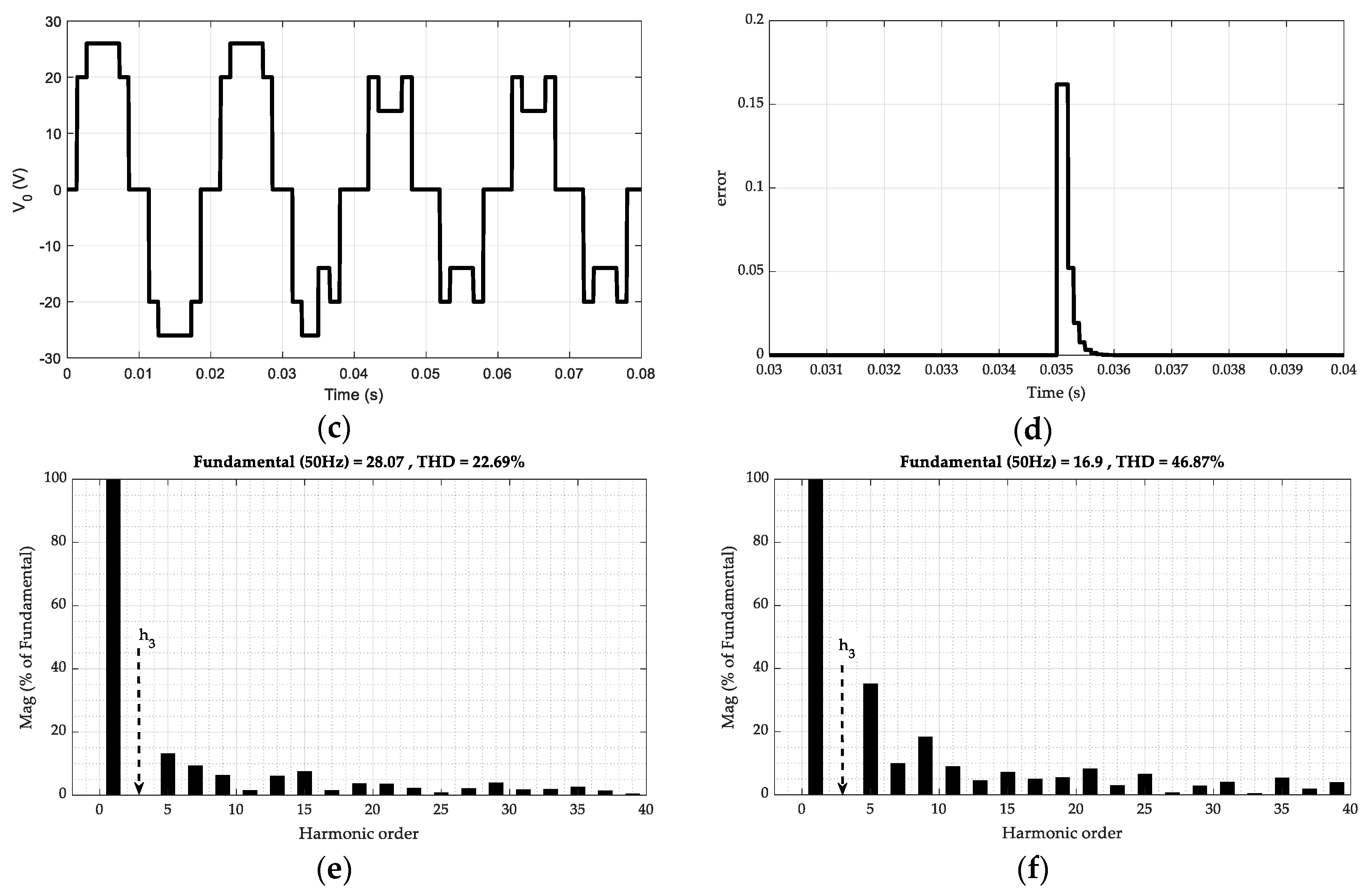
Figure 6 illustrates the dynamic performances of the first case study, where a step change in MI from 1.08 to 0.65 is applied at 0.035 s. The inverter was tested at , and to control the fundamental component while removing the third harmonic. Figure 6a shows the switching angles. The result shows that changes from 24.995° to 35.802°, whereas increases from 49.905° to 118.566°. If increases beyond 90°, this angle is modified by subtracting it from 180°, as shown by the dash dot waveform that decreases to 61.434° (180°−118.566°). On the basis of the calculated and , the control signals of the eight switches are generated to obtain the desired inverter output voltage. Figure 6b presents the lower (VL) and upper (VU) voltages, and Figure 6c depicts the resulting output voltage waveform. When the switching angles are lower than 90° (i.e., high MI), VL and VU are added to produce the output voltage. Otherwise, (i.e., low MI), the latter is subtracted from the former to determine the output voltage. The feedback controller is a simple proportional controller with a single parameter . The mechanism of this controller is simple, that is, increasing the gain until a stable operation is achieved. When , the controller delivers an extremely fast and stable response (Figure 6d). The simulation is conducted in MATLAB/Software®, and the sample time is set to 100 µs. The system reaches the steady state within 1 ms. This result suggests that the proposed technique has a small computation complexity and it can be easily used in real-time calculation. The fundamental component changes from 28 to 17 V as the MI changes from 1.08 to 0.65 (Equation (3)). Figure 6e,f shows the output voltage harmonic spectra of the two cases of MI. As previously stated, the third harmonic is removed in both cases.

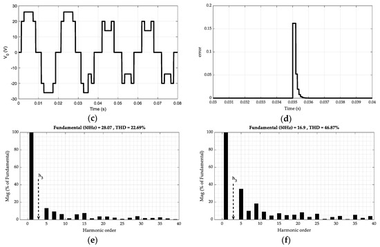
Figure 6.
Results of the first case study at , , and the third harmonic component is removed and the fundamental component is controlled by applying a step change in MI from 1.08 to 0.65 at 0.035 s: (a) and , (b) VL and VU, (c) resulting output voltage, (d) controller output signal, and (e,f) output voltage spectra.
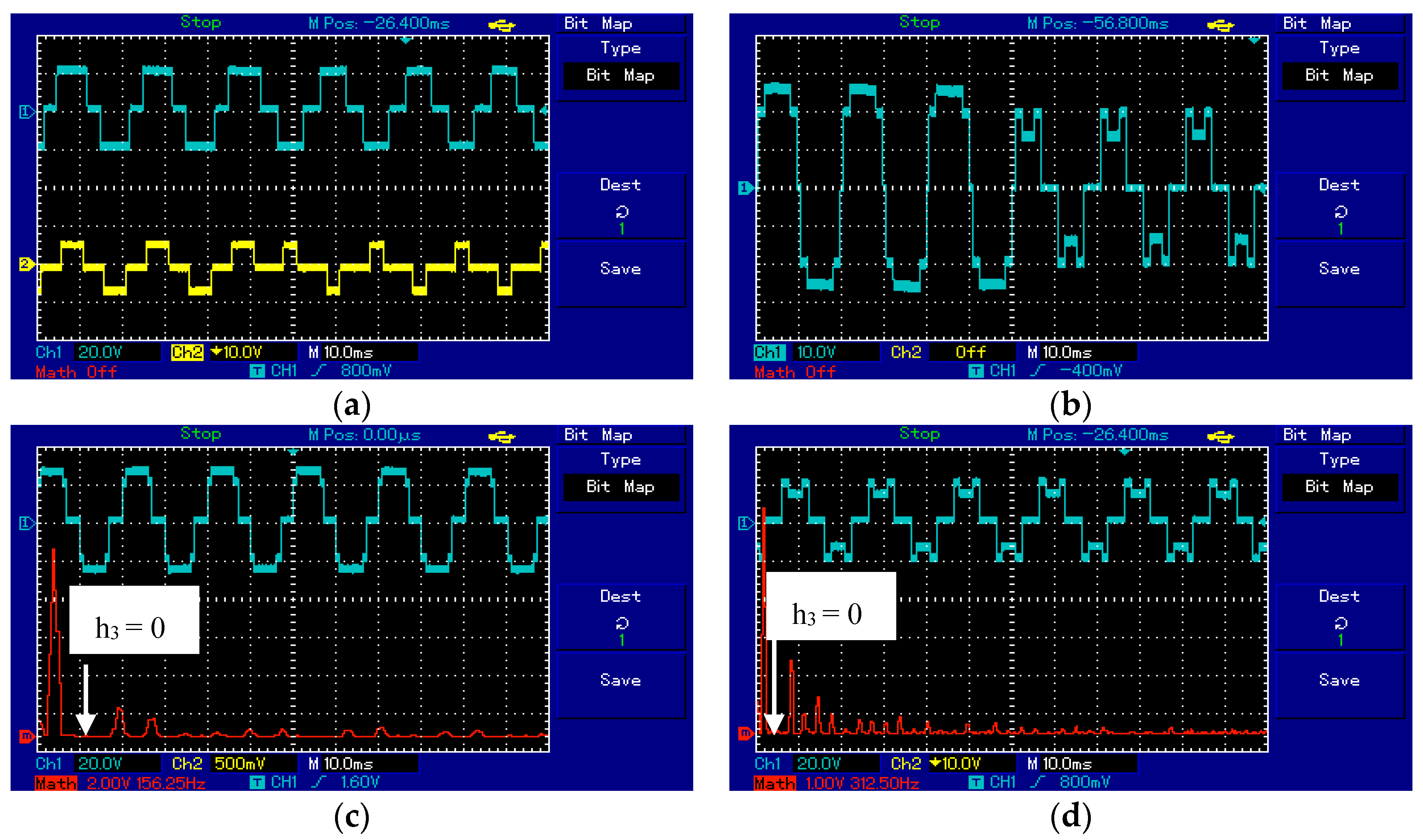
Figure 7 shows the experimental results due to the dynamic change in MI induced through the simulation parameters presented in Figure 6. The goal in the first and second durations, where MI is 1.08 and 0.65, respectively, is to control the fundamental component and remove the third harmonic component. Figure 7a shows the sudden changes in the separated upper and lower generated output MLI cells, and Figure 7b–d display the total output voltages of the MLI in the entire range, first duration, and second duration, respectively.
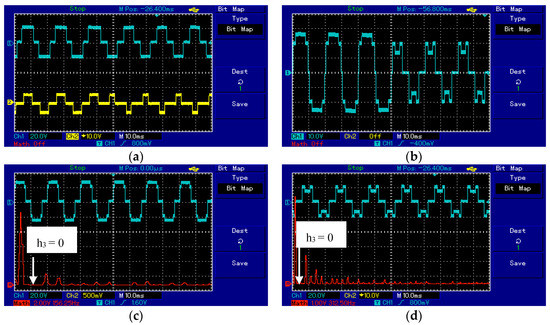
Figure 7.
Results of the first case study at , , and , in which the third harmonic component is removed and the fundamental component is controlled by applying a step change in MI from 1.08 to 0.65: (a) VU and VL, (b) resulting output voltage, and output voltage spectra at (c) MI = 1.08 and (d) MI = 0.65.
Case Study II:
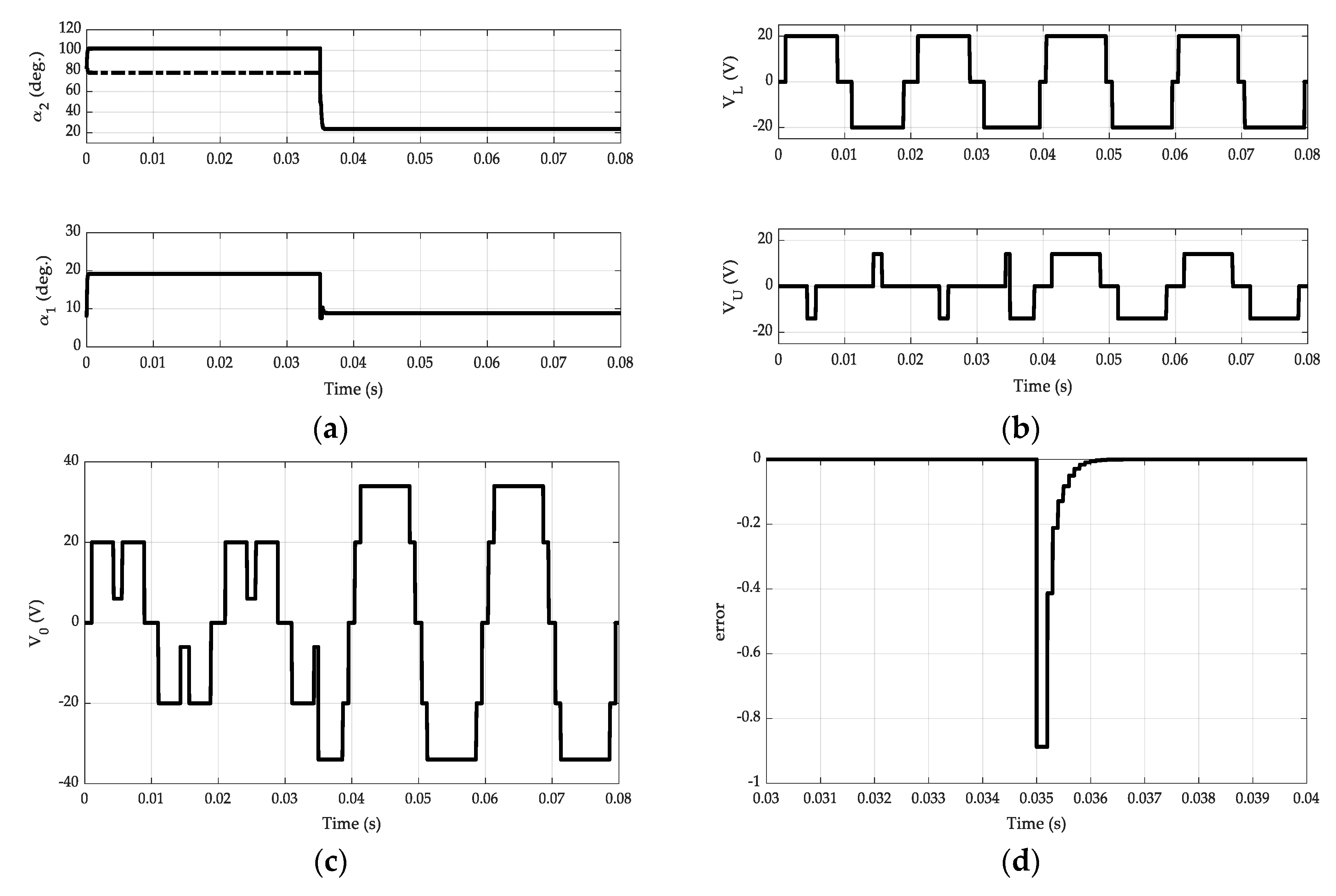
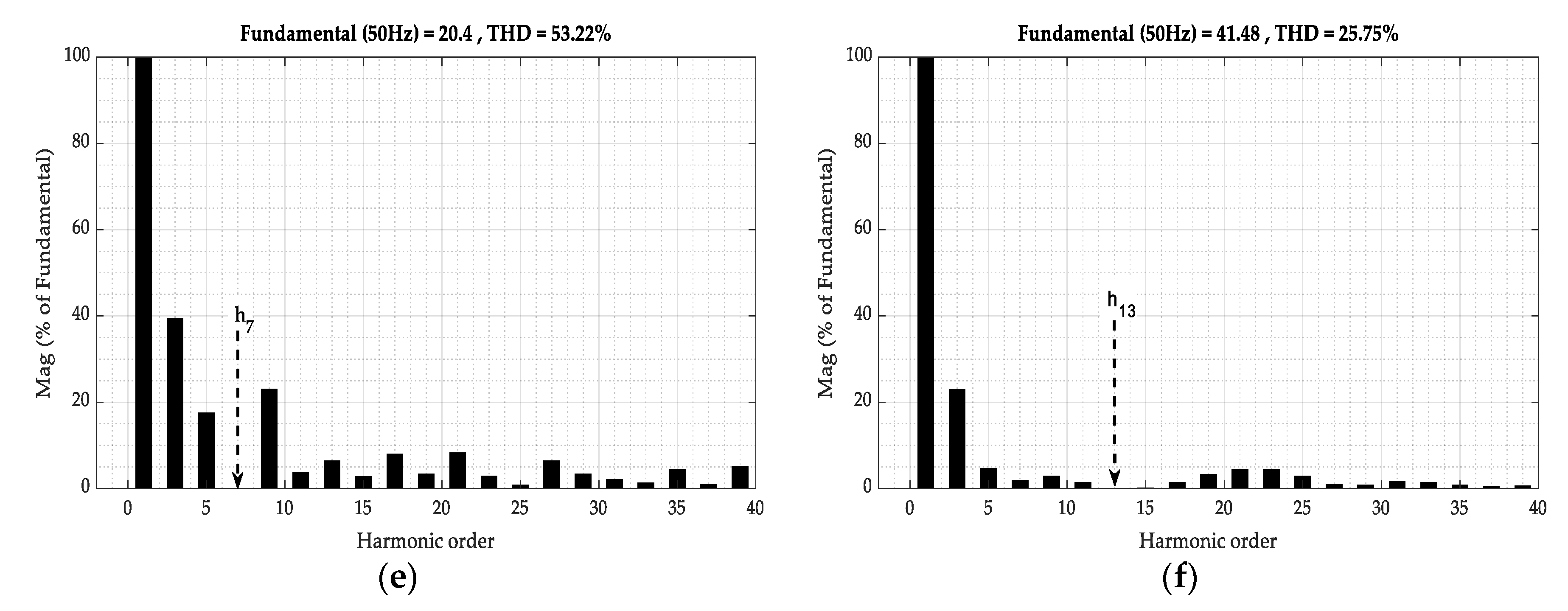
To further verify the effectiveness of the proposed algorithm, another case study is performed by applying a step change in MI from 0.6 to 1.22 at 0.035 s. The inverter was tested at , and . The goal in the first duration (t < 0.035 s), where MI = 0.6, is to control the fundamental component and remove the seventh harmonic component, whereas that in the second one (t > 0.035 s), where MI = 1.22, is to control the fundamental component and remove the 13th harmonic component. In the second duration, the 15th harmonic component is also removed. The simulation and experimental results of this case study are shown in Figure 8 and Figure 9, respectively. The findings are similar to those presented in Figure 6 and Figure 7, except for the obvious variations observed in the values of each variable. As shown in Figure 8a, exceeds 90° (solid line) and is therefore subtracted from 180° to obtain the accurate value (dashed line). The voltage of each cell is depicted in Figure 8b. The two voltages are subtracted in the first duration (low MI) and added in the second one (high MI) to obtain the desired inverter output voltage (Figure 8c). The subtraction or addition of VU and VL is achieved by generating the proper control signals of the power switches. Figure 8d displays the error signal, and thus confirms that the computation complexity is extremely small because the proposed algorithm rapidly reaches the steady state values of the switching angles. The Fourier spectra of both durations are presented in Figure 8e,f. The seventh harmonic component is fully removed in the first duration, whereas the 13th and 15th harmonic components are effectively deleted in the second one.
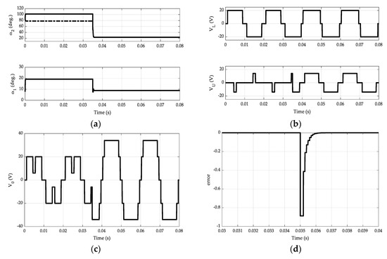
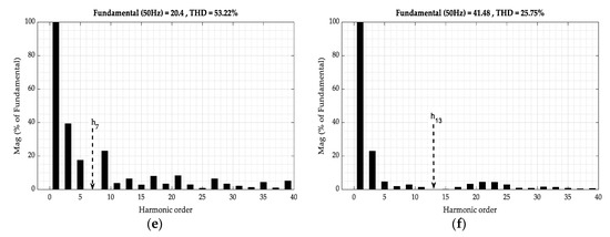
Figure 8.
Results of the second case study performances at , , and , in which the seventh and 13th harmonic orders are removed and the fundamental component is controlled by applying a step change in MI from 0.6 to 1.22 at 0.035 s: (a) and , (b) VU and VL, (c) resulting output voltage, (d) controller output signal, and (e)–(f) output voltage spectra.
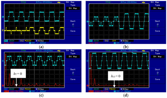
Figure 9.
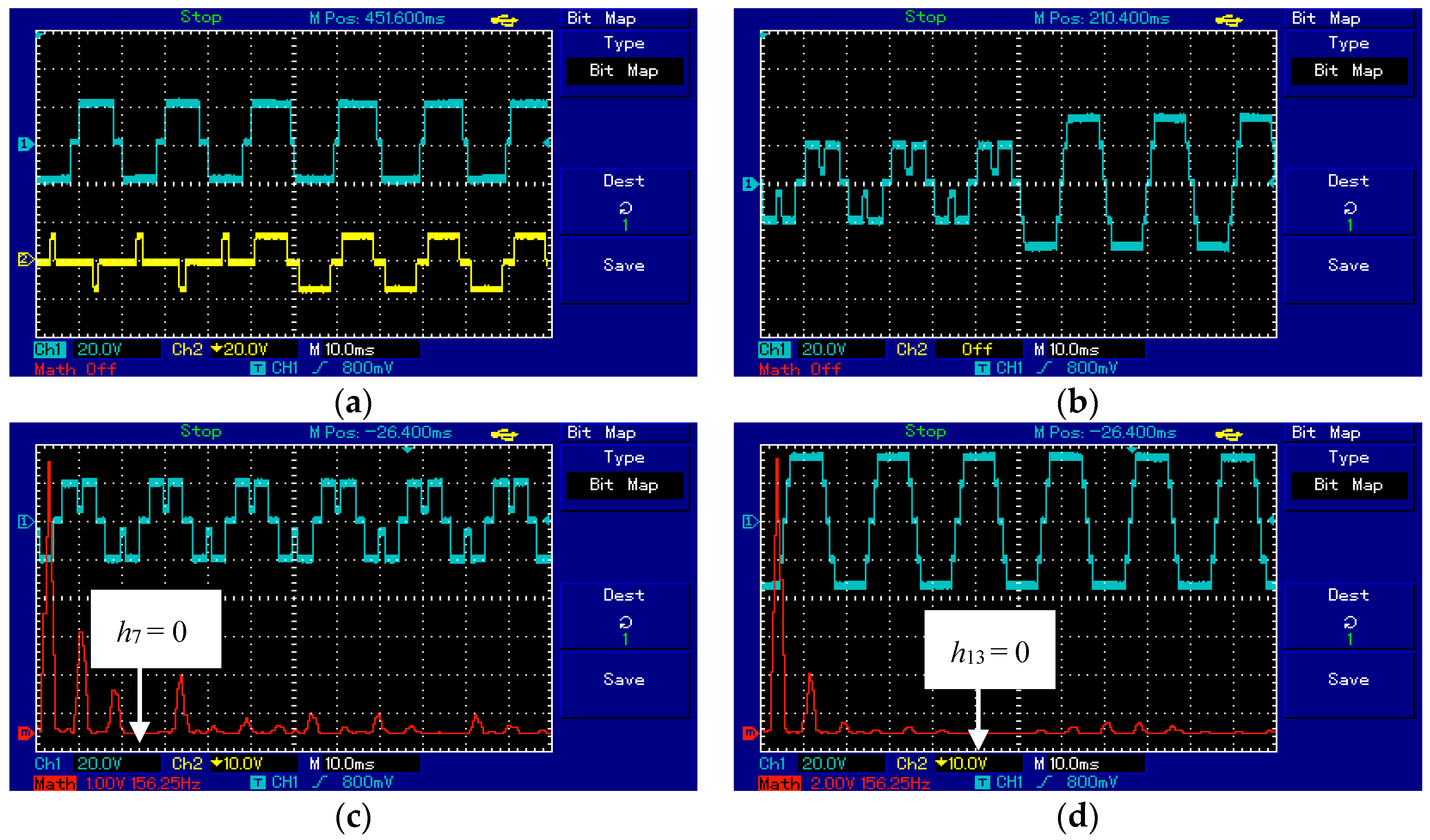
Results of the second case study at , , and , in which the seventh and the 13th harmonic orders are removed and the fundamental component is controlled by applying a step change in MI from 1.22 to 0.65: (a) VU and VL, (b) resulting output voltage, and output voltage spectra at (c) MI = 1.22 and (d) MI = 0.65.
Figure 9 shows the results due to the dynamic change in both MIs and removal of harmonic order, which is similar to the simulation conditions presented in Figure 8. Figure 9a depicts the sudden changes in the separated upper and lower generated output MLI cells, and Figure 9b–d shows the total output voltages of the MLI in the entire range, first duration, and second duration, respectively. The experimental results are extremely close to the simulated ones, thereby indicating the high performance and applicability of the proposed method in a wide range of MI.
4. Observations on the and Solutions
Figure 10 shows that when , the output voltage waveform in Figure 1b is generated; otherwise, the output voltage waveform in Figure 1c is produced. Therefore is an ideal border between the two waveforms. By using Equation (7), the corresponding in this condition can be calculated as , where is the stipulated removed harmonic order (n = 3 or 5 or 7 or 9, …).
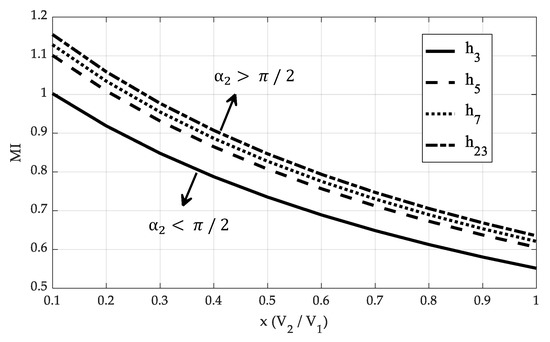
Figure 10.
Relationship among MI, x, and the removed harmonic order at the edge additive/subtractive of the DC sources.
Substituting Equation (6) yields
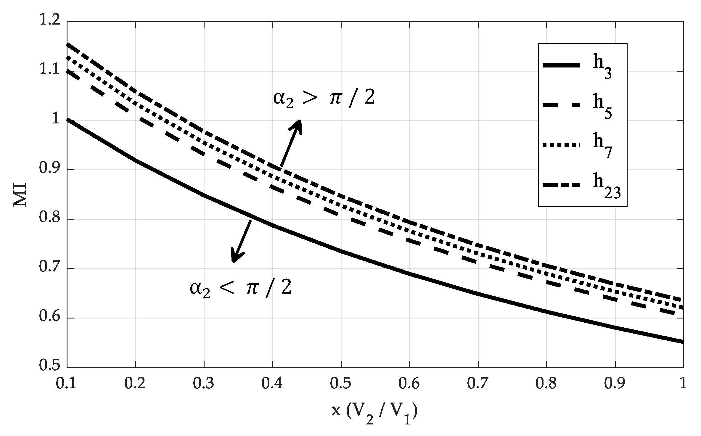
Equation (15) shows the relationship that defines which output voltage waveform will be generated. Figure 11 illustrates this relationship for the elimination of the third, fifth, seventh, and 23rd harmonic components. The region of the upper curve represents , which yields the output voltage waveforms shown in Figure 1b. By contrast, the region of the lower curve denotes , which produces the output voltage waveforms shown in Figure 1c.
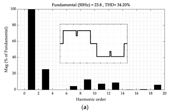
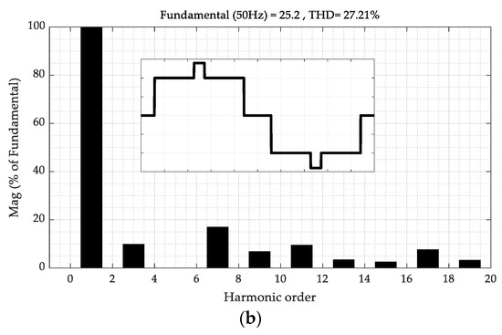
Figure 11.
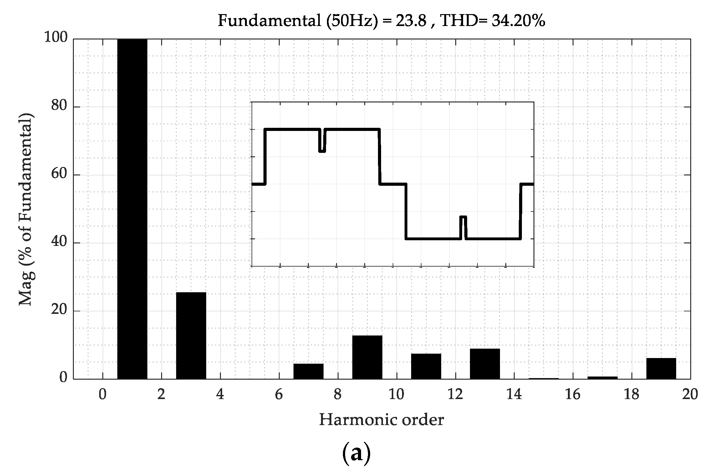
Change in the output voltage waveform due to α2 when x = 0.4 (V2 = 8 V, V1 = 20 V) and h5 is removed: (a) MI = 0.85 and (b) MI = 0.9.
Figure 11 illustrates how changes the output voltage waveforms. The removal of the harmonic h5 at x = 0.4 (Figure 10) is taken as an example. Given that the operation point is lower than the curve, MI = 0.85 (), and VU is subtracted from VL to generate the output voltage waveform (Figure 11a). If the operation point is located higher than the curve, MI = 0.9 (), and VU and VL are added to generate the output voltage waveform (Figure 11b).
5. Conclusions
In this study, a fast and easy solution that utilizes the classical proportional control algorithm and SHE technique to analyze the unequal DC sources of a five-level inverter is proposed to calculate the switching angles of MLI ( and ). The proposed method is applicable to renewable energy systems because it can overcome the mismatches among their generated DC sources. Two transcendental equations are formulated in terms of , , , and to verify two specified conditions. The two stipulated conditions are controlling the output voltage fundamental component and removing the extra single harmonic component. The advantages of the proposed technique are as follows.
- The proposed control algorithm is a simple proportional control (kp).
- The computational time complexity is minimal, and the proposed method can be easily implemented in real time.
- The proposed algorithm is fast and produces accurate solutions.
- The proposed technique is valid for a wide range of MI and x variations.
- The simulation and laboratory tests results match the analytical findings, and thus validate the proposed concept.
Suggested future research that can be performed with the existing technique is summarized in the following items.
- The proposed technique can be extended to a three-phase system.
- The proposed technique can be extended to higher MLI levels; thus more harmonic components can be removed, leading to decreasing the harmonic contents.
Author Contributions
Conceptualization, M.A. (Mahrous Ahmed) and E.H.; methodology, M.A. (Mahrous Ahmed) and E.H.; software, M.A. (Mahrous Ahmed), E.H. and S.G.; validation, M.A. (Mahrous Ahmed), E.H., and B.A.; formal analysis, M.A. (Mahrous Ahmed) and E.H.; investigation, M.A. (Mosleh Alharthi) and S.G.; resources, M.O. and S.M.; data curation, B.A. and F.S.; writing—original draft preparation, M.A. (Mahrous Ahmed) and E.H.; writing—review and editing, B.A., F.S., M.O., and S.M.; visualization, M.A. (Mosleh Alharthi), F.S., M.O., and S.M.; supervision, M.A. (Mahrous Ahmed), M.A. (Mosleh Alharthi), and S.G.; project administration, M.A. (Mahrous Ahmed), B.A., M.A. (Mosleh Alharthi), F.S., M.O., S.M., and S.G.; funding acquisition, M.A. (Mahrous Ahmed). All authors have read and agreed to the published version of the manuscript.
Funding
M.A., E.H., B.E., M.A., F.S., M.O., S.M., and S.G. would like to express their gratitude to the Scientific Research Deanship, Taif University, KSA, for its immense support under Grant No. 1-439-6072.
Acknowledgments
The authors would like to acknowledge the financial support received from the Scientific Research Deanship, Taif University, KSA, through grant no. 1-439-6072.
Conflicts of Interest
The authors declare no conflict of interest.
Abbreviation
Definitions and abbreviations used in the manuscript.
| MLI | multilevel inverter |
| SHE | selective harmonic elimination |
| THD | total harmonic distortion |
| and | switching angles |
| absolute error | |
| and | unequal input DC sources, |
| input DC source ratio, x = | |
| inverter output voltage waveform | |
| Fourier series components of the output voltage waveform | |
| modulation index ( | |
| non-normalized fundamental output voltage component |
References
- Debnath, S.; Qin, J.; Bahrani, B.; Saeedifard, M.; Barbosa, P. Operation, control, and applications of the modular multilevel converter: A review. IEEE Trans. Power Electron. 2015, 30, 37–53. [Google Scholar] [CrossRef]
- Schmidt, S.; Richter, M.; Oberrath, J. Control Oriented Modeling of DCDC Converters. Int. Fed. Autom. Control (IFAC) 2018, 51, 331–336. [Google Scholar] [CrossRef]
- Malinowski, M.; Gopakumar, K.; Rodriguez, J.; Perez, M.A. A survey on cascaded multilevel inverters. IEEE Trans. Ind. Electron. 2010, 57, 2197–2206. [Google Scholar] [CrossRef]
- Amjad, A.M.; Salam, Z. A review of soft computing methods for harmonics elimination PWM for inverters in renewable energy conversion systems. Renew. Sust. Energy Rev. 2014, 33, 141–153. [Google Scholar] [CrossRef]
- Jammala, V.; Yellasiri, S.; Panda, A.K. Development of a New Hybrid Multilevel Inverter Using Modified Carrier SPWM Switching Strategy. IEEE Trans. Power Electron. 2018, 33, 8192–8197. [Google Scholar] [CrossRef]
- Dahidah, M.S.; Konstantinou, G.; Agelidis, V.G. A review of multilevel selective harmonic elimination PWM: Formulations, solving algorithms, implementation and applications. IEEE Trans. Power Electron. 2015, 30, 4091–4106. [Google Scholar] [CrossRef]
- Colak, I.; Kabalci, E.; Bayindir, R. Review of multilevel voltage source inverter topologies and control schemes. Energy Convers. Manag. 2011, 52, 1114–1128. [Google Scholar] [CrossRef]
- Siddique, D.; Mekhilef, S.; Shah, M.; Sarwar, A.; Iqbal, A.; Memon, A. A New Multilevel Inverter Topology With Reduce Switch Count. IEEE Access 2019, 7, 58584–58594. [Google Scholar] [CrossRef]
- Buccella, C.; Cecati, C.; Cimoroni, M.G.; Kulothungan, G.; Edpuganti, A.; Rathore, A.K. A Selective Harmonic Elimination Method for Five-Level Converters for Distributed Generation. IEEE J. Emerg. Sel. Top. Power Electron. 2017, 5, 775–783. [Google Scholar] [CrossRef]
- Hasan, M.; Mekhilef, S.; Ahmed, M. Three-phase hybrid multilevel inverter with less power electronic components using space vector modulation. IET Power Electron. 2014, 7, 1256–1265. [Google Scholar] [CrossRef]
- Chiasson, J.N.; Tolbert, L.M.; McKenzie, K.J.; Du, A.Z. Elimination of harmonics in a multilevel converter using the theory of symmetric polynomials and resultants. IEEE Trans. Control Syst. Tech. 2005, 13, 216–223. [Google Scholar] [CrossRef]
- Yang, K.; Yuan, Z.; Yuan, R.; Yu, W.; Yuan, J.; Wang, J. A Groebner bases theory-based method for selective harmonic elimination. IEEE Trans. Power Electron. 2015, 30, 6581–6592. [Google Scholar] [CrossRef]
- Neralwar, K.S.; Meshram, P.M.; Borghate, V. GA based hybrid selective harmonic elimination (SHE) technique applied to five-level Nested Neutral Point Clamped (NNPC) Converter. In Proceedings of the IEEE 1st International Conference on Power Electronics, Intelligent Control and Energy Systems (ICPEICES), Delhi, India, 4–6 July 2016; pp. 1–6. [Google Scholar]
- Lee, S.S.; Chu, B.; Idris, N.R.N.; Goh, H.H.; Heng, Y.E. Switched-Battery Boost-Multilevel Inverter with GA Optimized SHEPWM for Standalone Application. IEEE Trans. Ind. Electron. 2015, 63, 2133–2142. [Google Scholar] [CrossRef]
- Hagh, M.T.; Taghizadeh, H.; Razi, K. Harmonic minimization in multilevel inverters using modified species-based particle swarm optimization. IEEE Trans. Power Electron. 2009, 24, 2259–2267. [Google Scholar] [CrossRef]
- Sundareswaran, K.; Jayant, K.; Shanavas, T. Inverter harmonic elimination through a colony of continuously exploring ants. IEEE Trans. Ind. Electron. 2007, 54, 2558–2565. [Google Scholar] [CrossRef]
- Balasubramonian, M.; Rajamani, V. Design and Real-Time Implementation of SHEPWM in Single-Phase Inverter Using Generalized Hopfield Neural Network. IEEE Trans. Ind. Electron. 2014, 61, 6327–6336. [Google Scholar] [CrossRef]
- Ahmed, M.; Hendawi, E.; Taha, I.B.M. Simple analytical solution for selective harmonic elimination technique. IET Electron. Lett. 2016, 52, 749–751. [Google Scholar] [CrossRef]
- Ahmed, M.; Orabi, M.; Sheir, A. Real Time Solution and Implementation of Selective Harmonic Elimination Using Classical Control. IEEE J. Emerg. Sel. Top. Power Electron. 2017, 5, 1700–1709. [Google Scholar] [CrossRef]
- Zhao, H.; Jin, T.; Wang, S.; Sun, L. A Real-Time Selective Harmonic Elimination Based on a Transient-free, Inner Closed-Loop Control for Cascaded Multilevel Power Inverters. IEEE Trans. Power Electron. 2016, 31, 1000–1014. [Google Scholar] [CrossRef]
- Ahmed, M.; Orabi, M.; Ghoneim, S.; Alharthi, M.; Alameri, B.; Salem, F.; Mekhilef, S. General Mathematical Solution for Selective Harmonic Elimination. IEEE J. Emerg. Sel. Top. Power Electron. 2019. [Google Scholar] [CrossRef]
- Ji, Y.H.; Jung, D.Y.; Kim, J.G.; Kim, J.H.; Lee, T.W.; Won, C.Y. A Real Maximum Power Point Tracking Method for Mismatching Compensation in PV Array under Partially Shaded Conditions. IEEE Trans. Power Electron. 2011, 26, 1001–1009. [Google Scholar] [CrossRef]
- Fares, D.; Fathi, M.; Mekhilef, S. Comparison of Two Hybrid Global Maximum Power Point Algorithms for Photovoltaic Module under Both Uniform and Partial Shading Condition. In Proceedings of the 2020 International Conference on Electrical, Communication, and Computer Engineering (ICECCE), Istanbul, Turkey, 12–13 June 2020. [Google Scholar]
- Filho, F.; Tolbert, L.; Yue, C.; Ozpineci, B. Real-time selective harmonic minimization for multilevel inverters connected to solar panels using artificial neural network angle generation. IEEE Trans. Ind. 2011, 47, 2117–2124. [Google Scholar] [CrossRef]
- Ahmed, M.; Orabi, M.; Ghoneim, S.; Alharthi, M.; Alameri, B.; Salem, F.; Mekhilef, S. Selective harmonic elimination method for unequal DC sources of multilevel inverters. J. Control Meas. Electron. Comput. Commun. 2019, 60, 378–384. [Google Scholar] [CrossRef]
- Kamani, P.L.; Mulla, M.A. Middle-Level SHE Pulse-Amplitude Modulation for Cascaded Multilevel Inverters. IEEE Trans. Ind. Electron. 2018, 65, 2828–2833. [Google Scholar] [CrossRef]
© 2020 by the authors. Licensee MDPI, Basel, Switzerland. This article is an open access article distributed under the terms and conditions of the Creative Commons Attribution (CC BY) license (http://creativecommons.org/licenses/by/4.0/).

