1. Introduction
Today alternative energy sources are commonly used in industrial microsystems, such as battery-less applications, self-powered sensors, and low-current communication modules [
1]. Particularly, in Reference [
1] the energy harvester achieves over 60 mW power in the pressing process. It is presented that the harvested energy is enough to supply the radio frequency integrated circuit (RFIC) low power transmitter, which signal is successfully detected by the receiver with an amplitude of −28.44 dBm. Industrial application of so-called “green energy”, which uses the piezo elements of a small scale in renewable energy sources, is given in Reference [
2]. The actual idea of Industry 4.0, i.e., Internet of Things (IoT), accounting for an energy harvesting system, where the intelligent electric energy management methods are employed. One example of this system developed by Cypress, Texas Instruments, and Maxim Integrated, was described in Reference [
3]. In that study, the vibration energy harvesting system, which can generate up to 150 mW power is proposed. In the era of miniaturization, manufacturers encourage the support of compact devices using piezo elements, which serve for charging LED flashlights or individual device functions [
4]. The “smart clothes” new fabric harvests energy from its wearer [
5,
6,
7], i.e., using piezo elements incorporated in the wearable patch which generate the usable electric energy. The authors in Reference [
8] investigated an optimal inertial power harvester for human-powered devices, where the output power seems to be useful for continuously operating motion powered wireless health sensors and other low-power devices. On the other hand, the electronics industry also strives to reduce electric energy consumption by replacing sensors with the low-power ones.
In the rotational machines, vibration monitoring systems are usually powered by an external source [
9,
10]. The commonly used and high accuracy torsional vibration transducer vibrometer is proposed in Reference [
9]. However, that solution is still expensive and gives similar results to the sensors based on the piezo elements. Similarly, in Reference [
10], the authors have developed expensive equipment for the vibration measurement using the ultrasonic sensor attached to the casing. The effectiveness of the method was demonstrated with simulation results. The autonomous machine monitoring unit with the wireless sensor module, where the piezo electronics were used to the vibration measurement and energy harvesting, is given in Reference [
11]. This energy harvesting system can provide the battery charging time up to 100 s. The magnetic sprung generator is another method of vibration measurement using energy harvesting, where the influence of the vibration frequencies on the amount of the harvested energy is the main studied effect [
12]. In that work, the simulation and experimental results confirmed the correctness of this sprung generator designs, and harvested power up to 80 mW was obtained with appropriate excitation. Design of vibration exciter by using the permanent magnets in the piezoelectric energy harvester, where the effect of magnets size, air-gap dimension, and pole array distribution was studied, is presented in Reference [
13]. In that work, the presented vibration energy harvesting system based on the structure of the piezo generators, and the rotor speed was in the range 0–1000 rpm. Moreover, the optimal air-gap and dimensions of the magnets were determined for the selected angular speeds. The most important conclusion was that the polarity of the poles had the greatest influence on the piezo voltage output. However, in Reference [
13], the simple test-rig is given with the static air-gap. In our work, the given results are provided for a wide variety of air-gaps and rotational speeds. Moreover, in this work, the rotor is levitated magnetically. This is supported by two radial active magnetic bearings, and macro fiber composite (MFC) cantilever configuration includes four sets around the rotor. In Reference [
14], the authors developed a piezoelectric cantilever array for broadband vibration harvesting, where the influence of the weight and dimensions of the bracket is studied. Experimental tests were carried out by binding the cantilever with a different mass. Multiple cantilevers with a different resonant frequency are operating with frequency in the range of 200–300 Hz. Excitation was carried out using an electromagnetic shaker. The authors in Reference [
14] claimed that by adding mass and extending the mount, higher values of the stored harvested energy can be achieved. The rotational energy harvesting using bi-stability and frequency up-conversion for the low-power sensing application is discussed in Reference [
15]. The bi-stability energy harvester operation was derived using two external magnetic forces, and the output power 52.3 μW was obtained when the excitation frequency was over 11 Hz.
In this paper, the energy harvesting prototype based on the macro fiber composite (MFC) piezoelectric elements, is applied in the active magnetic bearing (AMB) rotor application. The MFC-piezo elements configuration, together with permanent magnets, provide the rotor radial vibration energy harvester prototype. The proposed method of energy harvesting is based on the rotor radial vibration energy transfer to the MFC piezo configuration using the contact-free magnetic coupling. Moreover, the MFC cantilever, together with the fabricated converter system, was proposed as the rotor vibration sensors. The MFC element deflection depends on the rotor air-gap. Thus, the MFC element deflection measurement enables us to obtain the rotor displacements in the given axis with high accuracy. The harvesting energy is used to supply the MFC transducer converter electric circuit itself and enables us to obtain a self-powered MFC-based vibration sensor. The self-powered MFC-magnet based rotor vibration sensor is an attractive solution comparing with eddy-current or laser-based displacement low-power sensors. To assess the accuracy of the MFC-magnet based rotor vibration sensor, the experimental results are compared with measurements obtained using fiber optic sensors. Furthermore, the self-powered sensor prototype presented in the paper is a low-cost solution that can be integrated into the rotational machines in the feedback control or as the system health diagnostic.
The main contributions of this paper are as follows:
Novel (patented) contactless MFC-magnet based rotor radial vibration energy harvesting prototype;
Self-powered rotor vibration sensor;
Adjusted MFC harvested energy conditioning system;
experimental verification of MFC-magnet based energy harvester system for the active magnetic bearing rotor;
Study of magnetic coupling parameters and its influence on harvested electric energy amount at different rpm’s;
Experimental verification of MFC-magnet based self-powered vibration sensor accuracy compared with precise fiber optic based displacement sensor.
The paper is organized as follows. In
Section 2, analytical input and the energy harvester prototype idea is described.
Section 3 gives an overview of the AMB rotor and MFC-magnet harvesting system set-up. In
Section 4, experimental results and measured energy harvesting performance are presented, respectively. The paper ends with conclusions and future aspects.
2. Energy Harvester Prototype Description
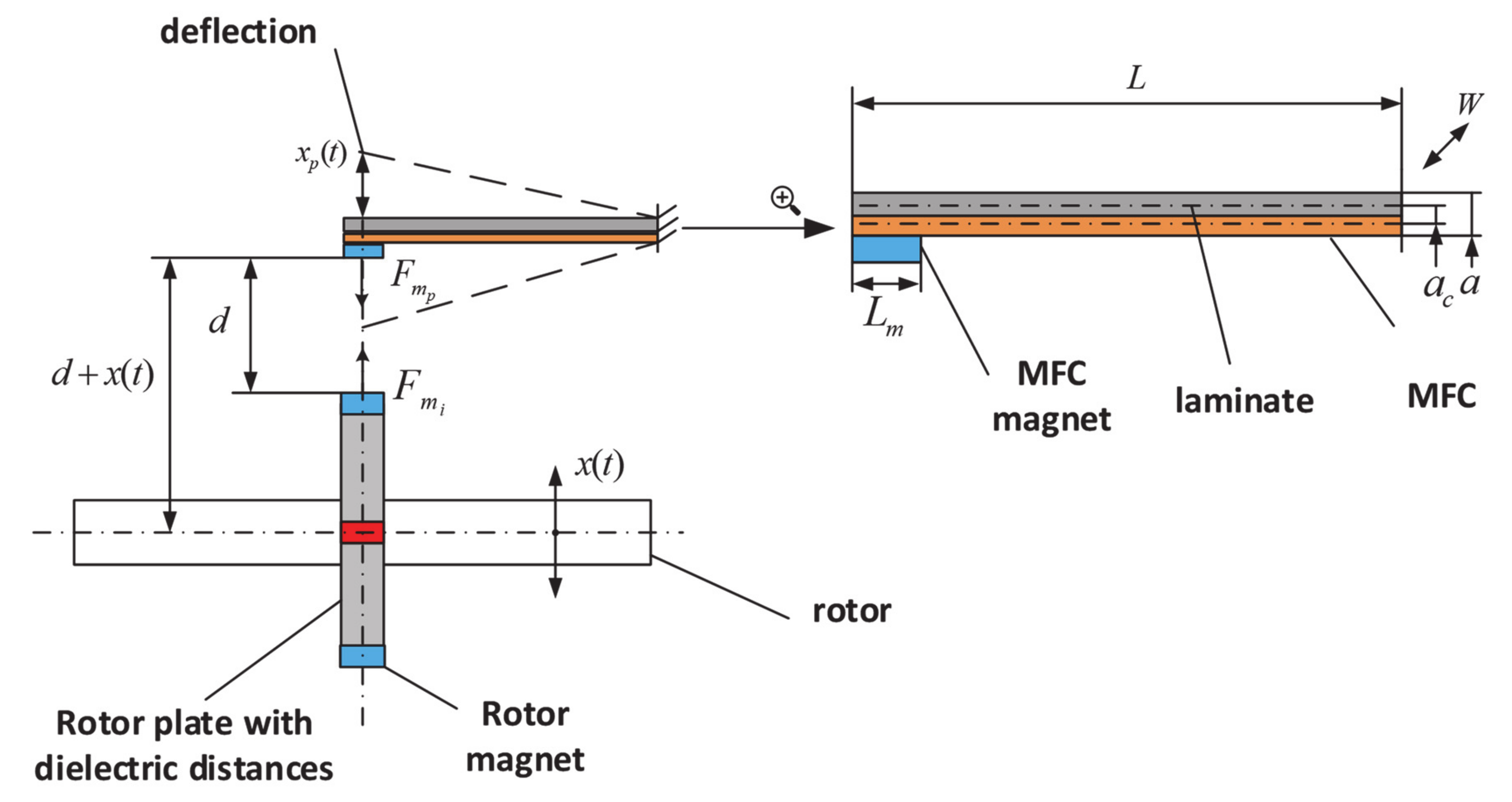
The mechanical model of the MFC-magnet based energy harvester (with magnetic coupling) is given in
Figure 1. We assume that the energy harvester can be modeled as an electromechanical system with mass, spring, damper, and piezo structure [
16,
17,
18].
If forces act only in the vertical axis, the motion equation has the form
where
is the rotor displacement,
is the MFC cantilever deflection,
m is the equivalent mass of the cantilever beam,
is the equivalent damping of the beam,
k is the equivalent stiffness,
is the generated voltage,
is the magnetic force of MFC-magnet and
is the force of successive rotor permanent magnets, where
. Because the magnets on the rotor are alternately arranged, it can be assumed that successive directions of force will be in the function of the sine-the next extreme positions with a sign change, assuming that the magnets force on the rotor is identical, Equation (1) can be rewritten as
According to the technical data of neodymium magnets for the desired dimensions, the maximal force of the rotor magnets is 14.7 N, while the maximal force of the MFC-magnets is 19.6 N. Notice that the . The deflection is also strongly influenced by the MFC material properties. In our application, the MFC material proved to be a 1 mm thick laminate; at the same time, we have rejected steel and aluminum assembling, due to too high stiffness.
Furthermore, piezoelectric constitutive equations in the reduced form are, [
19]
where
and
is the stress (N/m
2)and strain,
is the Young’s modulus at the constant electric field,
is the piezoelectric stress coefficient,
is the applied electric field (V/m),
and
is permittivity (F/m) with constant strain value. In Equations (3) and (4), subscripts {
1} and {
3} represent the measurement direction. Thus, Equation (4) can be rewritten as
However, the electric field
can be described using the voltage across the connected load
and dimension
(see
Figure 1)
Generally, the stress
along the beam length in the piezoelectric layer is expressed as
where
is the moment of the end mass and
is the moment of the inertia. According to the Equation (2) and assuming that the force acts on the center of the magnet, the moment can be described as
Therefore, Equation (7) becomes
Stress in the piezo layer varies on the length, so average stress is given as, [
20]
Linking (6) and (10), Equation (5) can be rewritten
Electric charge is created between two electrodes of piezoelectric materials when the materials are exposed to an external mechanical strain. The electric charge generated on the electrode with width
and length
is given by
and the load resistance current is
Simplification of Equation (13) is
where
is the capacitance of piezoelectric and
θ is the induced damping parameter. Equation (14) is the electrical circuit equation of the piezoelectric energy harvester, called as electromechanically coupled governing equation [
19,
20].
The MFC-magnet energy harvester prototype principle of operation is given in
Figure 2. This system uses the magnetic coupling for transfer the rotor radial vibration energy to the four MFC beams. The pole array distribution of the Neodymium Iron Boron (NdFeB) permanent magnets (NSNS) placed on the rotor interact with the pole array of magnets (SSSS) located on the MFC substrate (laminate) beam, which produces deflections. The proposed magnets configuration enables us to generate in one axis attraction force and the repulsive force in another axis a given time. The main advantage of this configuration is that at any time, the total force acting on the rotor is zero and does not produce external vibrations. For each laminate beam, the acting force is changing from repulsive to the attraction one and in the opposite direction. The radial air-gap
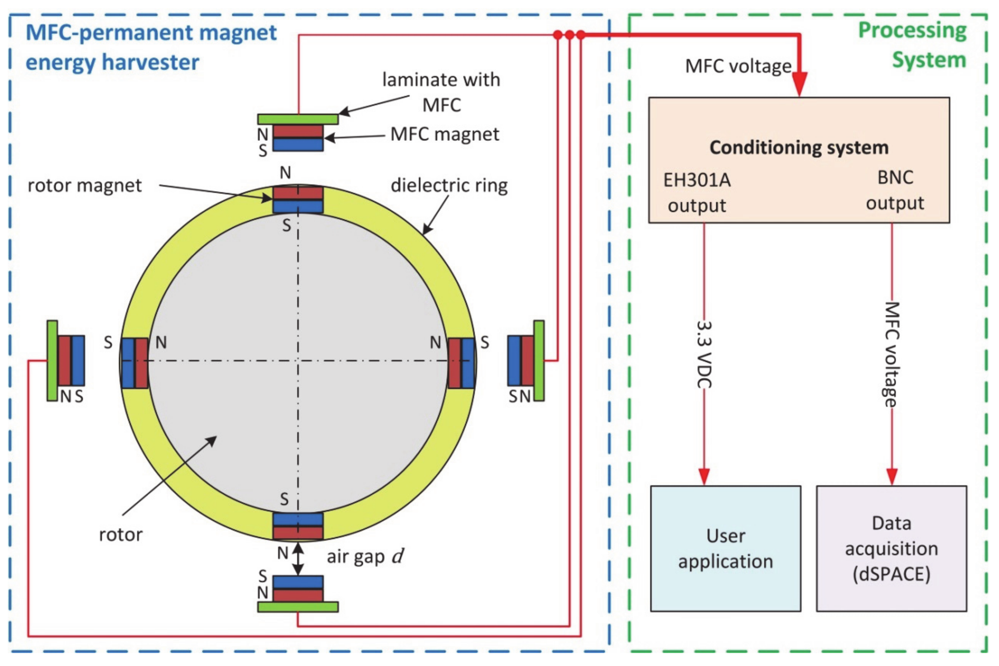
d between the rotor magnets and MFC magnets strongly influences the value of harvested electrical energy. This clearance is the main adjustable parameter in the proposed prototype, and its effect on the MFC harvesting system performance is investigated.
In particular, the neodymium magnets mounted at the free end of the MFC substrate beam are excited by the rotor magnets resulting bending deformation of the MFC cantilevers. In this way, we generated electric energy through the interaction between both arrays of the permanent magnets working as the vibration exciter. The maximal amplitude of the excited vibration depends on the magnet array geometry, width of the air-gap
d, and rotor vibration level. To determine the optimum conditions in order to harvest as much as possible electric energy, a set of experimental measurements are conducted where the main parameter, such as distance between the two magnet arrays and rotor speed are varied. The harvested energy is obtained from the four MFC elements with parallel connection, and is stored in the energy harvesting module EH301A, see
Figure 2. Detailed electrical connections of the four MFC cantilever outputs to the EH301A module is shown in Figure 11.
Optimization of the MFC Cantilever Beam Energy Harvester
The mechanical structure and shape of the MFC-magnet energy harvester must be optimized, due to the specified natural frequency in order to harvest maximal energy. The first eigenmode of the fixed-free beam is close to the deformation curve subjected to a uniform load. The energy generated by the piezoelectric layer in the case of linear deformations is proportional to the magnitude of the deformation in that layer. The equation of the deformation curve of the MFC cantilever deformation cantilever beam subjected to a uniform load at
p is as follows:
The deformations caused by the strains
S1 are effective; thus, strain component
S1 is:
where
z is the cantilever deflection coefficient. The plane strain energy
U is determined by integrating over the upper plane of the cantilever:
where
H is the height of the beam. The Equation (17) can be rewritten
The first eigenfrequency of the cantilever is given as
where
ρ is the material density. To select the geometrical parameters, the optimization tasks can be formulated
The cost function given by Equation (20) includes three main optimization parameters, such as
L, W, and
H, that may be found at the specified eigenfrequency.
Figure 3 shows that the amount of the harvested energy depends on the length of the harvester and is strongly nonlinear in comparison to the width linear dependence.
Figure 4 shows the relative dependence of the harvested energy field values on the length and width of the MFC-magnet energy harvester, which properly adjusts the dimensions to ensure the maximal amount of energy supplied. Particularly,
Figure 4 gives the energy field values, where the width and length are relative to the cantilever total width and length dimensions, thus the axes are in dimensionless form.
In order to increase the efficiency of the energy harvester, one of the most effective ways is to achieve the significant amount of energy was to the optimize cantilever configuration for the second eigenmode of the transverse oscillations (see
Figure 5). Such excited by the magnetic forces cantilever vibrates exceptionally at the second eigenmode of the transverse oscillations.
Due to some manufacturing complications, a simpler shape construction is possible, where the cross-section of the beam is increased to dimensions of
x/l = 0.24 placed from the fixed location (see
Figure 5, bottom). The second eigenmode of the oscillation of such a structure is shown in
Figure 6, and a possible optimized MFC-magnet energy harvester structure is given in
Figure 7. Particularly,
Figure 6 gives a total relative bending deflection of the cantilever, where deflection in
y axis is relative to the cantilever total length
L. In this Figure, the denominator
l is changed by
L, and the axes are in dimensionless form.
Figure 8 presents the voltage signals with time collected by the three PZT segments (0.24 L, 0.76 L, 0.2 L, respectively) of the MFC-magnet energy harvester, where
T is the cantilever vibration period.
The highest voltage amplitude is observed for the second PZT segment of the MFC energy harvested when it is oscillating at a frequency of the second eigenmode.
3. Experimental Set-Up
The experimental set-up consists of 4 main elements: Motor, two radial heteropolar active magnetic bearings (AMBs), safety ball bearings, a rotor with two unbalance disks, and the energy harvester system. The AMB detail description and overview of the AMB test rig is given in the previous studies [
21,
22]. Is given in the previous paper [
21,
22]. The AMB electromagnetic force is a nonlinear function of the coil current and rotor displacement. At the operating point defined by the bias clearance 0.0004 m and bias coil current 2.5 A, the nominal values of current and displacement stiffness of the radial magnetic bearing are 13.2 N/A and 82,000 N/m, respectively. The system offers several rotor configurations in the horizontal axis. The total rotor mass equals 6 kg, and spindle AC motor with inverter enables us to achieve rotor speed in the range 0–24,000 rpm. The radial AMBs are enclosed by a housing which consists of the stator, two-axes eddy-current displacement sensors, and touchdown ball bearings (emergency support). The rotor has two unbalance disks, which enable the unbalance load. The test rig model is presented in
Figure 9.
The MFC cantilever is attached to the flexible glass-epoxide TSE-5 substrate (laminate) of 1 mm thickness. This substrate ensures nominal bending deflection resulting in generated voltage output. Moreover, in the proposed MFC cantilevers configuration, the MFC element should transfer bending vibrations without affecting the entire frame of the prototype. The MFC element is fixed to the TSE-5 laminate using flexible glue Z70 of HBM, which ensures MFC cantilever bending amplitudes up to 10 mm. The neodymium magnets with dimensions of 2 × 3 × 20 mm (on the rotor disk unbalance) and 5 × 2 × 20 mm (on the free end of the MFC beam) are applied. The self-powered vibration sensor performance is compared with the rotor displacement measurements provided by the fiber optic PHILTEC RC62-T2 sensor developed by
philtec.com, which is not sensitive to magnetic field changes. The analog sensor RC62-T2 has a high sensitivity of 3 mV/µm, standard DC-20 kHz bandwidth, and the reflectance compensated output. Both sensors are placed in the same plane at the rotor unbalance disk. The technical data of the sensor is given in
Table 1.
The experimental set-up is shown in
Figure 10. The rotor is driven by the AC motor, and two radial AMBs are driven by the power amplifier based on the pulse-with-modulation (PWM). The AMBs are controlled by the feedback control system realized on the digital signal processor, Expansion Box PX10, developed by the dSPACE, thus, the stability of the rotor magnetic suspension is ensured.
The energy storage system is based on the EH301A module. Four MFC piezo elements are connected to the EH301A in a parallel way. The MFC cantilever and EH301A electric measurement connections are shown in
Figure 5. The constant output voltage
of the EH301A module is active after charging up the capacitors to the voltage range between
and
. The stored energy can be used for various purposes, e.g., microsystems, low-power sensors, or low-power wireless modules. In our case, the diode with nominal current consumption of 20 mA is used to check how long it can be powered from the stored energy (see
Figure 11). This will allow us to evaluate the suitability of the developed energy harvesting system for further applications.
The specification of the EH301A module is collected in
Table 2. In the EH301A module, the first output with BNC socket is used for MFC transducer voltage measurements via A/D card with the input impedance of 1 MΩ of the digital signal processor Box P10 of dSPACE, whereas the second one is used as the stable output power supply for DC diode with conventional 3.3 VDC. Moreover, the first output is further used for the rotor radial vibration measurements. The EH301A module is designed to continuously and actively operating to capture, accumulate, and conserve energy from an external energy source. The MFC-based energy source injects energy into the inputs of the EH301A module in the form of electrical charge impulses; these charge packets are collected, accumulated, and stored onto an internal storage capacitor bank.
The MFC piezo, developed by Smart Materials GmbH, type M8514P2, and incorporated in the harvester frame, are given in
Figure 12.
Macro Fiber Composites (MFCs) are very effective piezoelectric transducers that can produce energy harvesting from mechanical vibrations. The harvesting energy depends on the total deflection of the MFC. This deflection in our application is limited by the rotor air-gap and the repulsive or attraction force produced by the configuration of the permanent magnets. Therefore, it is important that the MFC cantilever should operate with a frequency close to the eigenfrequency of the system. However, the total harvesting energy is limited by MFC element properties and dimensions. Moreover, this kind of harvesting system must be designed by considering all phenomena that could limit the total harvested energy. One of them is the temperature fluctuation during the device operation. Another disadvantage of the MFC cantilever is their fragility, which can provide to damage during handling and assembly. The P2 type of the MFC element has a high electric source capacitance, low output voltage, and increased electric charge generation, which make this MFC cantilever well suited for vibration harvesting application. In comparison to other piezo ceramic harvester devices, the standard MFC element is delivered unattached to a structure or cantilever. This attaches to vibration nodes of mechanical structures and is one of the important features of using the flexible MFC transducer for energy harvesting applications. It also allows for the design of non-resonant harvesters. The technical specifications of the MFC element are presented in
Table 3.
The MFC cantilever consists of rectangular rods, which are arranged between the adhesive layers, the electrodes, and the polyimide film. The electrodes are attached to the web in a parallel arrangement. This kit provides polarization, start-up, and detection in a closed and durable package. A thin sheet that is compatible with the surface can be applied to a composite structure.
4. Experimental Results and Discussion of the MFC-Magnet Energy Harvester
This section presents experimental results that verify the prototype designs and performance. The main goal of the research is to get optimal conditions for the system parameters, such as the air-gap d between the magnets and rotor rotational speed. These parameters influence the total harvested energy is investigated. The experimental study is divided into three following steps:
Examination of the capacitor charging time, due to the air-gap width;
Examination of the capacitor charging time, due to the rotor rotational speed;
Evaluation of the MFC-magnet self-powered vibration sensor output with fiber optic output.
These tests are carried out in the same conditions and settings of the hardware. The measurements and data acquisition are carried out using ControlDesk software and the digital signal processor of dSPACE. The fixed sampling time is equal to 0.0001 s. For the given AMB test rig, the rotor was well balanced with the Schenck balancer with accuracy up to 0.0001 kg.
The first set of measurements present the capacitor voltage output versus the air-gap and rotor speed in the time domain.
Figure 13 shows the capacitor charging effect dependence on the air-gap
d = 24 mm and three rotational speeds: 1150, 2150, and 3150 rpm.
The capacitor output voltage fast increase occurs at the beginning of the measurement, in the time range 0÷10 s, when the rotor is accelerating from angular speed 100 to 500 rpm. There is a rapid bending vibration of the MFC piezo elements. For the angular speed of 3150 rpm, the capacitor is charged to almost 1 V in the time 500 s. The output is activated when the level is reached. In this case, charging the capacitor up to 5.3 V would take about 44 min.
Another significant phenomenon we can discover in these capacitor voltage trajectories that the energy MFC-based energy harvester has a wide range of resonant frequencies in contrast to a conventional piezoelectric ceramic, which has a fixed resonant frequency [
23]. As can be observed, the output power is strongly depending on the rotor vibration amplitude changes. Moreover, the output voltage depends on the level of the magnetic coupling, which transfers the mechanical energy; these intensities can be increased using the Halbach arrays [
24].
Figure 14 shows the capacitor charging when the air-gap
d = 20 mm. In this case, decreasing the air-gap by 4 mm results in decreasing the capacitor charging time by approx. 2.5× for the highest rotational speed. As a result, the capacitor output voltage over 2.5 V is achieved in the time 500 s, when the rotor speed is equal to 3150 rpm.
Finally, the minimum value of the air-gap
d = 16 mm is obtained to prevent the mechanical contact between the MFC-magnet and rotor magnet arrays, respectively. The capacitor output voltage time response for the air-gap
d = 16 mm is given in
Figure 15.
In this case, during the charging mode, the capacitor output voltage achieves the high-level in the time up to 100 s for the rotor angular speed 3150 rpm. Then, the output voltage is activated, and the 20 mA diode was powered up. After that, during the discharging mode, the capacitor voltage decreases to low-level , and the is deactivated. For lower rotational speeds r = 1150 and 2150 rpm, the charging time is approx. 460 and 310 s, respectively.
The discharging mode of the MFC-magnet configuration is presented in
Figure 16. Where the approximate duration of the continuous discharging from the high-level voltage
V to the low-level voltage
V equals 4.1 s.
It should be outpointed here, that the capacitor is not fully discharged, and the recharge time does not exceed 40 s. The capacitor charging and discharging times are important in the face of the usable energy. The usable harvested energy can be further used to supply, i.e., external device or sensor.
In order to calculate the harvesting energy, it was assumed that the voltage
and current
of the capacitor, with capacity
and load
is related to the time
as follows:
However, power
used for transferring a small load
from one capacitor cover to the other, assuming one of the covers is charged with load
is described
The harvesting energy stored in the capacitor is calculated by integrating the (22), resulting in:
In our application, capacity
C is equal to 4700
µF and voltage
U is the maximal capacitor voltage. Thus, the electric power, for the MFC energy harvester charging time
t is given by
. Measured electric performance of the MFC-magnet energy harvesting system is collected in
Table 4.
To conclude, among the results obtained in
Figure 13,
Figure 14,
Figure 15 and
Figure 16, as was expected, the smaller size of the air-gap, the greater the mechanical energy transferred to the MFC beam, and therefore, the higher output power. The effect of distance between two magnets and its influence on the output voltage is similar to observed in Reference [
25], where the results show that the position that is close to the fixed end of the PZT cantilever and the relative motion along the long side gives higher power output. The output power is increasing together with the excitation frequency. The highest output power is obtained at both the resonant harvester frequency and high rotor frequency. Considering that the MFC cantilever is excited four times per one rotor rotation, the MFC element excitation resonant frequency is up to 210 Hz. This resonant frequency is almost eight times higher in comparison with the results presented in Reference [
13], where the piezoelectric ceramic cantilever beam is operated with the four rotor-magnet arrays at rotor speed 400 rpm. According to the power analysis, the obtained max. power of 673.47 μW is significantly greater in comparison with the rotational energy harvester with output power 52.3 μW presented in paper [
15]. On the other hand, the experiments proved a strong influence of the magnetic coupling to the output power. Therefore, the air-gap between the magnet and magnet size has to be always adjusted to the desired power output. The measurements are provided for the calibrated MFC energy harvester, and every single test was repeated two times. The measurement uncertainty is not defined, since it is insignificant. Another method to increase the harvested energy is to use a stronger magnet to match the stronger magnetic forces [
26]. Moreover, the MFC-piezo’s optimal position is essential for energy harvesting, since the location influences the beam deflection and stiffness [
27].
Experimental Setup and Results of the Self-Powered Vibration Sensor
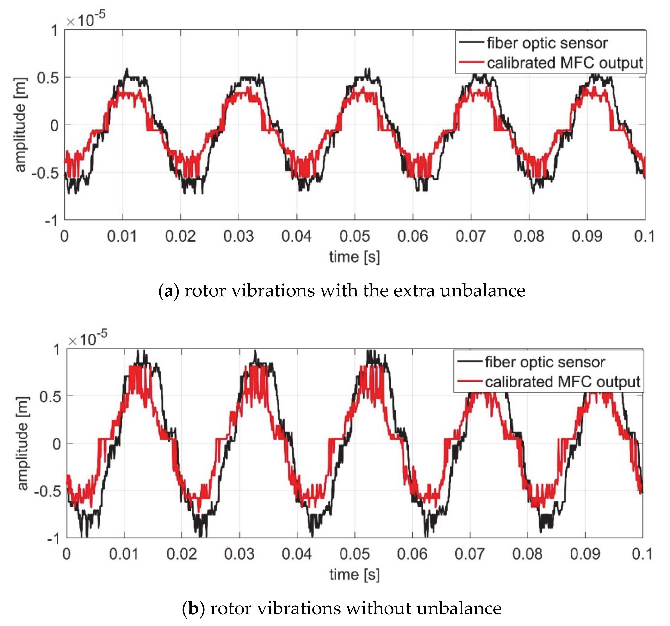
The last set of measurements presents an investigation of the MFC-magnet self-powered vibration sensor. The MFC-magnet configuration is used to measure the rotor radial displacements in the
x–
y directions. In order to verify the rotor vibration sensitivity, the fiber optic laser sensor is used. This sensor is placed close enough in the
y-axis of the rotor unbalance disk, see
Figure 17. Moreover, since the fiber optic sensor has a high measurement resolution, it is suitable as the feedback sensor in the closed-loop rotor position control system. The obtained MFC transducer voltage was calibrated in order to match the voltage amplitude of the laser sensor
. Where
is calibrated MFC transducer output,
is the constant gain,
is the raw MFC transducer output voltage, and
is offset. In particular, the system gains, such as
= 15.75 and
= 0.0073, were estimated based on the fiber optic sensor output. The rotor vibration measurements are carried out for the constant rotational speed of 3150 rpm, and with/without extra unbalance mass
of 0.0128 kg at radius
= 35 mm. The system configuration during the rotor vibration measurements is shown in
Figure 17.
The measured rotor displacements, in the
y axis, is shown in
Figure 18, where the fiber optic sensor output is compared with the MFC-magnet sensor output, for the balanced and unbalanced rotor. In both cases, the MFC-magnet sensor output fits well with the fiber optic sensor output. However, the MFC-magnet sensor output is not smooth enough as in the fiber optic sensor, where the output voltage is filtered and stabilized using the sensor proximity.
Figure 18a shows the rotor vibration waveforms without the unbalance, and the maximal vibration amplitude vary approx.
m, while in the case of the unbalanced rotor, the maximal vibration amplitude is twice bigger and equals
m (see
Figure 18b).
According to the results given in
Figure 18, the extra unbalance mass enables us to obtain a higher rotor displacement amplitude, due to the active damping of the AMBs. The mismatched vibration amplitude for both sensors does not exceed 1 μm. The difference of the rotor vibration between MFC-magnet and fiber optic sensors could has arisen from the inaccurate calibration of the MFC transducer output voltage. Moreover, there was no possibility to locate the fiber sensor tip exactly in the
y axis, see
Figure 17.
5. MFC-Magnet Halbach Array Energy Harvester
The neodymium magnet Halbach array is an arrangement of permanent magnets that creates a stronger field on one side, while reducing the field on the other side to almost zero. This is a well-known solution to increase the magnetic flux and increase the magnetic force in the axis. The MFC-magnet Halbach array energy harvester enables us to transmit the mechanical energy of the rotor vibrations more effectively, since the high flux density resulting in the highly attractive or repulsive magnetic forces. Moreover, the MFC-magnet Halbach energy harvesting system will be enough for power a low-current Hall sensor in the flux-controlled AMB system operated with zero-bias flux. In addition, we plan to determine the geometry of the structure of the piezo elements in the AMB rotor system in order to maximize the harvested energy.
With the increasing use of the Internet of Things for technological devices, it is necessary to envisage the applications of the MFC-magnet energy harvester for wireless technologies that enable remote monitoring of technological devices.
Figure 19 shows the proposed complete architecture of the wireless energy generator.
To increase the effectiveness and sensitivity of the MFC-magnet energy harvester 1, the resonant frequency of transverse vibrations
Fmp is tuned by changing the concentrated inertial mass 2, which approaches the frequency of
Fmi.
Figure 20 suggests that the measured maximal output voltage of the rotor without unbalance vibration harvester is 2 V (blue color). The generated voltage of the harvester exponentially rose until the capacitor was fully charged, and a wireless signal is sent to the receiver. The signal sending time intervals amounted to ~6 s. The accelerometer signal is marked in red color.
When the rotor is unbalance, the signal amplitude of the accelerometers (see
Figure 21), as well as the frequency of wireless transmission of the measured results increase; while the time interval decreases by approximately 2–3 times every ~2–3 s.
The harvested electricity charges the capacitor, which when charged up to 2 V, sends a signal to the receiver (smartphone). If the rotor unbalance increases, then the frequency of the transmitted signals also increases—which indicates the technical health condition of the rotor system.
6. Summary
In this paper, we have designed, fabricated, and investigated a new energy harvesting device to obtain usable electric energy using the MFC piezo elements and neodymium magnets. The proposed prototype of the rotor radial vibration energy harvester based on the MFC elements configuration with contact-less magnetic coupling is experimentally validated. We have presented an experimental study of the major system parameters, such as air-gap between two magnets and rotor angular speed, as well as their influence on the energy harvesting performance. The harvested energy is stored in the capacitor-based module. For the minimum width of the air-gap d = 16 mm, the high-level capacitor voltage V is obtained in the time 100 s, when the rotor angular speed was 3150 rpm. The capacitor recharging time of 40 s is achieved, when the capacitor voltage increases from the low-level , to the high-level , for the rotor speed 3150 rpm. The maximal obtained harvested power equals 673.47 μW.
The MFC-magnet configuration is also used as the self-powered rotor vibration sensor. The experimental results obtained when comparing the indications of the fiber optic sensor with the MFC-magnet sensor output voltage are fit well, which indicates the usefulness of the proposed system in the measuring application. The obtained difference between the rotor vibration amplitude for both sensors does not exceed 1 μm.
The MFC cantilever with the contactless magnet-based vibration energy harvesting prototype is already patented with the title: “Device for recovery and conversion of mechanical energy from radial vibrations of machine rotor or shaft into electrical energy, introduces neodymium magnet arrangement on the periphery of the rotor and at micro fiber composite (MFC) elements”. Patent number PL425303-A1; PL234703-B1. International Patent Classification: H02N-002/18.


