Article

A Powerful Build-Up Rate (BUR) Prediction Method for the Static Push-the-Bit Rotary Steerable System (RSS)

1
School of Petroleum Engineering, China University of Petroleum (East China), Qingdao 266580, China
2
Key Laboratory of Unconventional Oil & Gas Development (China University of Petroleum-East China), Ministry of Education, Qingdao 266580, China
3
CNPC Tarim Oilfield Company, Korla 841000, China
4
CNPC Chuanqing Drilling Co. Ltd., Guanghan 618300, China
5
Aerospace Science and Industry Inertial Technology Co. Ltd., Beijing 100074, China
*
Author to whom correspondence should be addressed.
Energies 2020, 13(18), 4847; https://doi.org/10.3390/en13184847
Submission received: 30 June 2020 / Revised: 15 September 2020 / Accepted: 15 September 2020 / Published: 16 September 2020
(This article belongs to the Section K: State-of-the-Art Energy Related Technologies)

Abstract

:
The RSS has been widely used in directional drilling. In order to enhance wellpath control accuracy and efficiency of the static push-the-bit RSS, a powerful BUR prediction method is reconstructed by coupling a rotary steerable bottom-hole assembly (RSBHA) mechanical model and a drill bit–rock interaction model. This article showed that when establishing the RSBHA mechanical model by using the continuous beam column method, the steering rib should be treated as an eccentric stabilizer to consider the contact effect between the steering rib and wellbore wall. For the beam column containing the flexible sub and between two stabilizers, it should be rearranged into three beam columns, and the lower and upper steps of the flexible sub should be considered as virtual supports. The equilibrium tendency method (ETM) to predict the BUR can enhance wellpath prediction accuracy than those of traditional methods. Under 3D conditions, the total drilling tendency angle should be denoted by inclination tendency angle and azimuth tendency angle to enhance the solution efficiency. Case analyses have verified that the average forecast error of the BUR prediction model in this article is less than 1°/30 m.

Graphical Abstract

1. Introduction

The RSS is a directional drilling system that performs continuous and real-time steering of the wellpath while the drill string is always rotating. Compared to the traditional sliding steerable system with a bent-housing downhole motor, the RSS can enhance the efficiency and accuracy of complex wellpath control. Now, the RSS is widely used in directional drilling [1,2,3,4,5]. According to the steering mode, the RSSs are divided into push-the-bit systems (for example, Baker Hughes’ AutoTrak RCLS/ Schlumberger’s PowerDrive system), point-the-bit systems (for example, Sperry-Sun’s Geo-Pilot system), and hybrid systems [6,7,8]. Among the RSSs, the AutoTrak RCLS belongs to the static push-the-bit RSS and is the original one put into industrial application in the world.
During the course of wellpath control, the key task is to predict and adjust the BUR to hit the target. The existing BUR prediction methods mainly include the three-point circular method (TPCM) [9,10] and its modified methods [11,12,13], the equilibrium curvature method (ECM) [14] and its modified methods [15], and the equilibrium tendency method (ETM) [16,17]. The TPCMs only consider the geometric configurations of the BHA. Its prediction accuracy is relatively low. The ECMs consider the geometric shape of the wellbore and the deformation of BHA. Its prediction accuracy is higher than that by means of the ECMs. Compared to the TPCMs and ECMs, the ETM additionally considers the anisotropic features of drill bit and formation. Its prediction accuracy is higher than those of the TPCMs and ECMs.
Now, the static push-the-bit RSS is being developed in China. The ETM has been tried to predict the BUR of RSBHA [18,19,20]. As more directional or horizontal wells have been drilled by more complex RSBHAs, it is urgent to set up a powerful BUR prediction method to provide guidelines to optimize the RSBHA and drilling parameters to predict and adjust the BUR accurately.

2. Modified RSBHA Mechanical Model

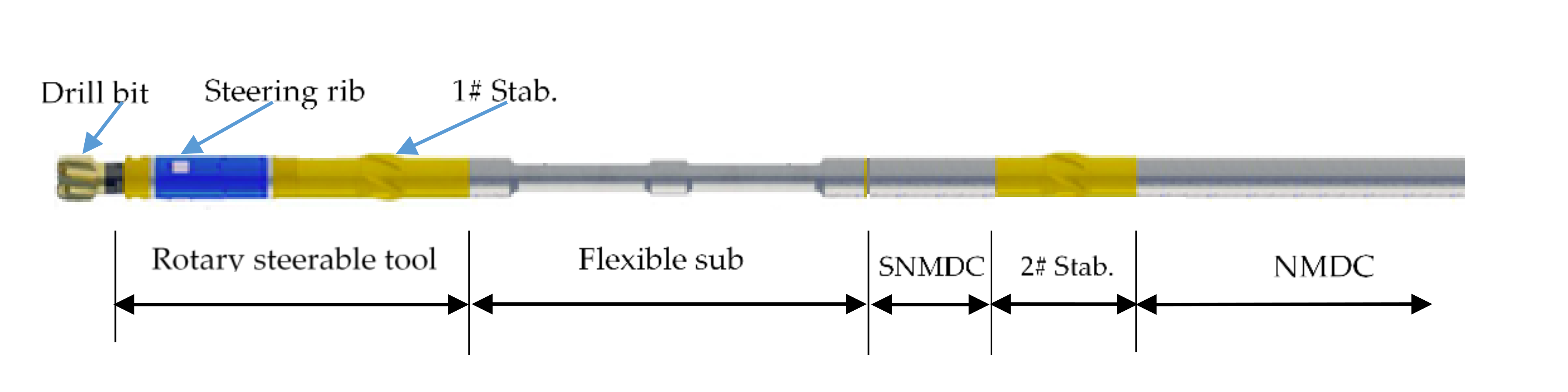
2.1. A Typical Static Push-the-Bit RSBHA

A reasonable BHA mechanical model is the basis to predict the BUR accurately. As shown in Figure 1, a typical static push-the-bit RSBHA includes a rotary steerable tool with a separated stabilizer (1# stab.), a flexible sub, a short non-magnetic drill collar (SNMDC), a drill string stabilizer (2# stab.), non-magnetic drill collars (NMDC), and a MWD (measurement while drilling) system inside of the NMDCs. Compared to previous configurations of RSBHA [18,19,20], the significant difference is that this one adopts two stabilizers. The 2# stabilizer can decrease the stick-slip vibration of the drill string to protect the MWD system.
A variety of methods can be adopted to establish the RSBHA mechanical model, including the finite element method [12,13], the weighted residual method [21], and the beam column method [22,23]. The beam column method is relatively simple and more accurate as compared to the abovementioned methods and has been employed in this paper.

2.2. Basic Assumptions to RSBHA

The following assumptions are generally adopted by the beam column method [24]:
(1)
The total RSBHA is a small elastic deformation system.
(2)
The center of a drill bit is located on the wellbore center line.
(3)
The weight-on-bit (WOB) is a constant value and along the tangential direction of the wellbore.
(4)
Due to the effect of the drill string gravity, the drill string above the upper tangential point lies on the lower side of wellbore.
(5)
The wellbore wall is a rigid body and the wellbore size does not change over time.
(6)
The contact between the stabilizer and wellbore wall is a point contact.
(7)
The effect of rotation and vibration of a drill string is not taken into account.

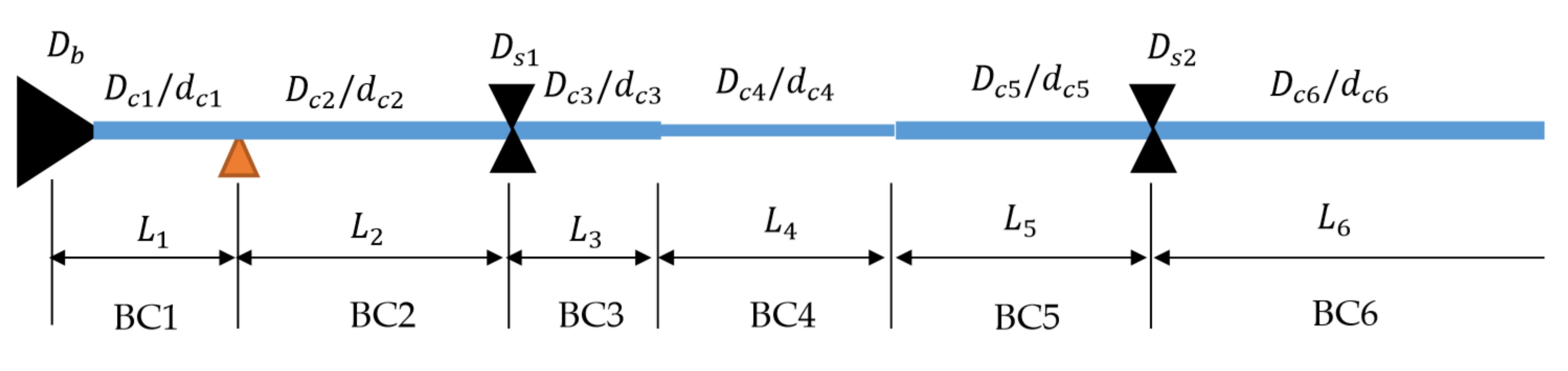
2.3. Equivalent Treatments of the RSBHA

When establishing the RSBHA mechanical model, the steering rib and the flexible sub should be simplified and treated reasonably. Now, there are two equivalent treatment methods to the steering rib. The first method took it as a laterally concentrated force with known magnitude and direction [23]. The second method considered the steering rib as an eccentric stabilizer with a known support force (equal to the steering force) and unknown eccentric displacement [20]. Based on the working principle of the static push-the-bit RSS, the support effect between the steering rib and the wellbore wall should be considered [25]. Hence, the second method is adopted in this paper. There are also two equivalent treatment methods to the flexible sub. The first method employs the theory of the Timshenko variable stiffness beam to directly calculate its eccentric displacement and tilt angle [23,26]. The second method takes the steps of the flexible sub as virtual supports with unknown internal bending moments and eccentric displacements [24]. Both methods have high computational accuracy. Because the second method is more simple than the first method, it is adopted in this article.

2.4. RSBHA Mechanical Model

Taking the steering rib as an eccentric stabilizer and the lower and upper steps of the flexible sub as two virtual supports, the modified RSBHA mechanical model is shown in Figure 2. Under this mechanical model, the RSBHA is divided into 6 beam columns at the steering rib, two stabilizers, and the lower and upper steps of the flexible sub. They are named as BC1 (drill bit to steering rib), BC2 (steering rib to 1# stabilizer), BC3 (1# stabilizer to lower step of the flexible sub), BC4 (between lower and upper steps of the flexible sub), BC5 (upper step of the flexible sub to 2# stabilizer), and BC6 (2# stabilizer to the upper tangential point between the drill string and wellbore wall). Here, D c i , d i , and L i denote the outer and inner diameters, and the length of the ith (i = 1~6) beam column, respectively; D b , D s 1 , and D s 2 denote the diameters of the drill bit and 1# and 2# stabilizers, respectively.
Compared to previous mechanical models of RSBHA [18,19,20], the significant differences are that two steps of the flexible sub are regarded as two virtual supports and the beam column between two stabilizers is divided into three spans with different diameters. In most cases, the lengths of BC3, BC4, and BC5 are in the range of 0.5–1.0, 1.0–4.0, and 4.5–6.0 m, respectively. The modified mechanical model of RSBHA can enhance the prediction accuracy of BUR.
When establishing the RSBHA mechanical model above, all three-moment equations and supplementary equations need to be derived by the continuity conditions at each stabilizer or virtual supports. To simplify the derivation process, suppose that the wellbore is a 2D arc and the resultant steering force is along the high or low side of the wellbore. The supplementary conditions and equations of the steering rib and the flexible sub can be derived as follows.

2.4.1. Basic Three-Moment Equations to the RSBHA

According to the beam column theory [24], basic three-moment equations corresponding to two stabilizers and the upper tangential point of the drill string and wellbore wall can be derived directly.
M i 1 Z u i + 2 M i Y u i + E I i L i + 1 E I i + 1 L i Y u i + 1 + M i + 1 E I i L i + 1 E I i + 1 L i Z u i + 1 = q i L i 2 4 X u i q i + 1 E I i L i + 1 3 4 E I i + 1 L i X u i + 1 + 6 E I i L i y i + 1 y i L i + 1 y i y i 1 L i ( i = 1 ~ 5 )
q 6 X u 6 L 6 4 + 4 2 M 6 Y u 6 + M 5 Z u 6 L 6 2 = 24 E I 6 L 6 K 1 6 L i y 6 + y 5
where E I i and u i denote the stiffness and the stability coefficient of the ith (i = 1~6) beam column, respectively; q i denotes the lateral uniform load of the ith beam column due to its gravity; X u i , Y u i , and Z u i denote the amplification factors for the tilt angle of the ith beam column end; M i and y i denote the internal bending moment and the height of the ith support, respectively; M 0 and y 0 denote the internal bending moment and the support height at the drill bit, respectively; K denotes the curvature of the wellbore; the other variables have the same meanings as above.
Please pay attention that the basic three-moment equations corresponding to beam columns BC1~BC5 have been uniformed to the first equation above.
Some parameters in Equations (1) and (2) should be calculated as follows.
P i = P i 1 1 2 w i 1 L i 1 cos α ¯ i 1 1 2 w i L i cos α ¯ i
q i = w i sin α ¯ i
α ¯ i = α 0 K j = 1 i 1 L j K L i 2
y i = K 2 j = 1 i L j 2 ± Δ i   i = 1 ,   3 ,   4 K 2 j = 1 i L j 2 ± D b D c i 2   i = 2 ,   5 ,   6
M 6 = E I 6 K
where w i P i , and α ¯ i denote the line weight, the midpoint axial load, and the average inclination of the ith (i = 1~6) beam column, respectively; Δ 1 , Δ 3 , and Δ 4 denote the eccentric displacements of steering rib and the lower and upper steps of the flexible sub, respectively; “+” denotes the contact between the stabilizer and the upper wellbore wall; “−” denotes the contact between the stabilizer and the lower wellbore wall; the other variables have the same meanings as above.
Regardless of the wellbore enlargement and the bending moment at the drill bit, let M 0 = 0, y 0 = 0, w 0 = 0, L 0 = 0, P 0   =   P b (weight-on-bit, WOB), and α 0   =   α b (inclination of the current wellbore bottom). All equations above contain 9 unknown parameters, M i (i = 1~5), L 6 , y 1 , y 3 , and y 4 . In fact, the eccentric displacements, Δ 1 , Δ 3 , and Δ 4 , are implicit in y 1 , y 2 , and y 3 , respectively. The number of the unknown values is greater than that of the given equations. Some supplementary equations to the steerable rib and the steps of the flexible sub must be added to the RSBHA mechanical model.

2.4.2. Supplementary Condition and Equation of the Steering Rib

As for the steering rib, the eccentric stabilizer treatment method is adopted. The first two beam columns BC1 and BC2 are picked out and showed in Figure 3. Here, the bending moments M 0 , M 1 , and M 2 are basic unknown parameters and the eccentric displacement Δ 1 is a supplementary unknown parameter.
The supplementary condition to the steering rib is that the support force is equal to the steering force and denoted by Equation (8).
F s = Q 1 R Q 2 L
where F s denotes the resultant steering force of steering rib; Q 1 R and Q 2 L are the shear forces corresponding to the right end of the first beam and the left end of the second beam, respectively.
According to the beam column theory [24], the supplementary equation was derived and showed by Equation (9). Here, M 1 , M 2 , and y 1 are unknown values; y 1 contains the additional unknown value Δ 1 (the eccentric displacement of the steerable rib).
M 0 L 1 1 L 1 + 1 L 2 M 1 + M 2 L 1 P 1 L 1 + P 2 L 2 y 1 = F s q 1 L 1 + q 2 L 2 2 P 1 y 0 L 1 P 2 y 2 L 2

2.4.3. Supplementary Condition and Equation of the Flexible Sub

As for the flexible sub, three beam columns BC3 to BC5 are picked out and showed in Figure 4. Here, the bending moments M i (i = 2~5) are basic unknown parameters, and the eccentric displacements Δ 3 at lower step and Δ 4 at upper step are supplementary unknown parameters and implicit in y 3 and y 4 . Two supplementary conditions are required to derive two supplementary equations.
The supplementary condition to a step of the flexible sub is that the shear forces of two sides of the step are equal and denoted by Equations (10) and (11).
Q 3 R = Q 4 L
Q 4 R = Q 5 L
where Q 3 R and Q 4 L are the shear forces corresponding to the right end of the third beam (left side of the lower step) and the left end of the fourth beam (right side of the lower step), respectively; Q 4 R and Q 5 L are the shear forces corresponding to the right end of the fourth beam (left side of the upper step) and the left end of the fifth beam (right side of the upper step), respectively.
According to the beam column theory [24], the supplementary equations were derived and showed by Equations (12) and (13). Here, M i (i = 2~5), y 3 , and y 4 are unknown values; y 3 and y 4 contain the additional values Δ 3 and Δ 4 , respectively.
M 2 L 3 1 L 3 + 1 L 4 M 3 + M 4 L 4 = y 3 y 2 L 3 P 3 y 4 y 3 L 4 P 4 q 3 L 3 + q 4 L 4 2
M 3 L 4 1 L 4 + 1 L 5 M 4 + M 5 L 5 = y 4 y 3 L 4 P 4 y 5 y 4 L 5 P 5 q 4 L 4 + q 5 L 5 2
Up to now, all equations of the 2D RSBHA mechanical model are derived. All equations should put into one equation set and solved by numerical solution.

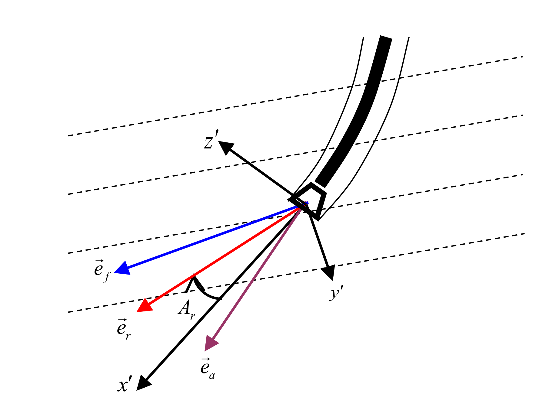
2.4.4. Simple Discussion of the 3D RSBHA Mechanical Model

The above 2D mechanical model is only applicable to 2D wellbores, and the tool face angle (TFA) is 0° (the steering force is along the high-side direction) or 180° (along the low-side direction). Under the other conditions, the 3D RSBHA mechanical model also can be established and solved according to the beam column theory [24]. In short, the 3D wellbore and 3D steering force all can be decomposed into the inclination plane P and the azimuth plane Q, and then, the 3D RSBHA mechanical model can be transformed into two 2D mechanical models and solved separately. The basic equation sets corresponding to the P and Q planes can be derived in a straightforward manner and omitted here.
The purpose to set up and solve the RSBHA mechanical model is to solve the lateral force(s) and tilt angle(s) of the drill bit, and then, predict the BUR. Here, only the equations involving lateral forces and tilt angles of the drill bit are listed and showed by Equations (14)–(17).
N b P = P b y 1 P L 1 + q 1 p L 1 2 + M 1 P L 1
A b P = q 1 p L 1 3 24 E I 1 X u 1 + M 1 p L 1 6 E I 1 Z u 1 y 1 p L 1
N b Q = P b y 1 Q L 1 + M 1 Q L 1
A b Q = M 1 Q L 1 6 E I 1 Z u 1 y 1 Q L 1
where N b P and A b P denote the lateral force and the tilt angle of the drill bit on the inclination plane P, respectively; N b Q and A b Q denote the lateral force and the tilt angle of the drill bit on the azimuth plane Q, respectively. Normally, when N b P and A b P are positive (along the high side of the wellbore), the inclination shows an increasing trend, while a decreasing trend is observed when N b P and A b P are negative (along the low side of the wellbore). When N b Q and A b Q are positive, it shows an increasing azimuth tendency, and there is a decreasing azimuth tendency if N b Q and A b Q are negative.

3. Modified BUR Prediction Method

3.1. Principle of the ETM and Its Modifications

The principles of the ECM and ETM are shown in Figure 5 [16]. Here, x indicates the current wellbore axial direction (tangential direction); z indicates the current wellbore high-side direction; y is determined by x , z , and the right-hand rule; unit vectors e r , e f , and e a denote the directions of the resultant drilling velocity (called as the drilling tendency direction), the resultant force, and the axial of the drill bit, respectively; the angle A r between the drilling tendency direction and wellbore axial direction is called the drilling tendency angle. If unit vector e r is above the x axis, it means that A r > 0; if e r is below the x axis, it means that A r < 0; if e r is along the x axis, it means that A r = 0.
The ETM considers that the drilling direction is determined by the resultant drilling velocity at the drill bit. If the lateral drilling velocity is not equal to 0, it means that A r ≠ 0, and then, the new drilling wellbore curvature will increase ( A r > 0) or decrease ( A r < 0). If the lateral drilling velocity is equal to 0, it means that A r = 0, and the new drilling wellbore curvature has reached to the equilibrium value and can be selected as the predicted BUR corresponding to the given drilling condition. Compared to the ETM, the ECM considers that the drilling direction is determined by the resultant force at drill bit. If the lateral component force ultimately turns into 0, the new drilling wellbore curvature is selected as the predicted BUR corresponding. In fact, only ETM combines with the drill bit–rock interaction model [26] and totally takes into account the effects of the wellbore geometry, the BHA mechanical model, and the anisotropic features of the drill bit and formation. As a result, its BUR prediction result is relatively accurate.
The ETM requires a trial and error approach. Under the 3D condition, the BUR is related to the inclination and azimuth. It is difficult to adjust the next trial value of BUR (wellbore curvature) based on the previous value of A r . In view of this problem, A r is decomposed onto the P and Q planes, denoted by inclination tendency angle ( A P ) and azimuth tendency angle ( A Q ), respectively. These two factors are employed to test the trial values of inclination and azimuth. The effect of formation anisotropy is ignored in this analysis. A simple and practical set of equations for the inclination tendency angle A P and azimuth tendency angle A Q are derived as follows.
A P = tan 1 P b 1 I b tan A b P + N b P tan 2 A b P + I b P b 1 + I b tan 2 A b P + N b P 1 I b tan A b P A Q = tan 1 [ P b 1 I b tan A b Q + N b Q tan 2 A b Q + I b P b 1 + I b tan 2 A b Q + N b Q 1 I b tan A b Q ]
where I b denotes the drill bit anisotropic index; the subscript p indicates the P or Q plane.

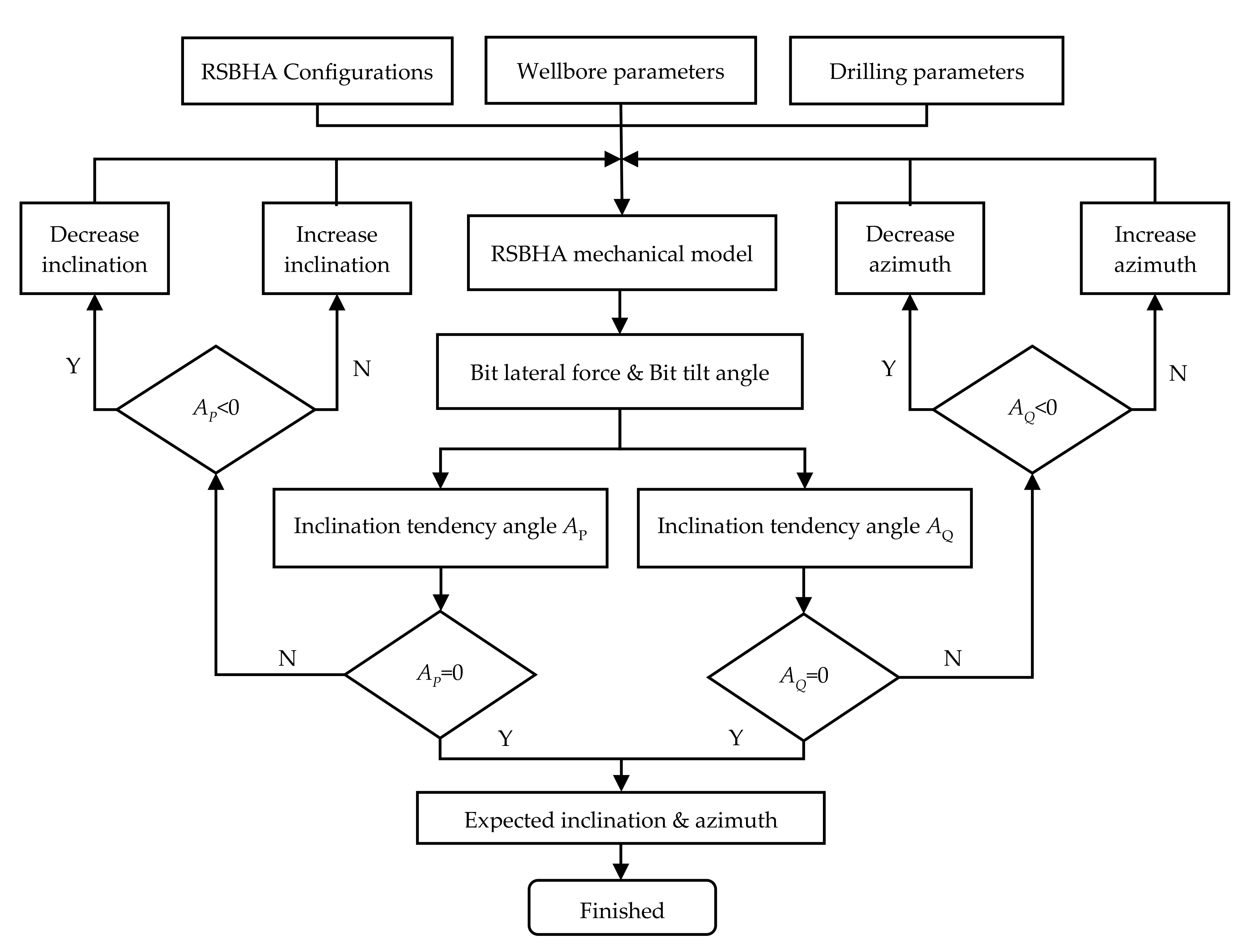
3.2. Solution Procedure for the ETM

Taking the 3D problem as an example, the modified procedure for predicting the BUR by the ETM is shown in Figure 6. According to the given drilling conditions, the inclination and azimuth are estimated at first. Then, the above RSBHA mechanical model is applied to obtain the lateral forces and tilt angles of the drill bit on the P and Q planes, respectively, and finally, Equation (18) is used to calculate the inclination tendency angle A P and azimuth tendency angle A Q . If A P ≠ 0 or A Q ≠ 0, then inclination or azimuth are re-estimated, and the above calculation steps are repeated. When re-estimating the inclination and azimuth, if A P > 0 or A Q > 0, the estimation values are adjusted to increase the inclination change rate or azimuth change rate; otherwise, if A P < 0 or A Q < 0, the inclination or azimuth estimation are adjusted to decrease the inclination change rate or azimuth change rate. After several trial calculations, if A P ≈ 0 and A Q ≈ 0, the trial calculation is terminated. Simulation analysis shows that the modified method can be used to adjust the trial values of inclination and azimuth after the previous trial, which can significantly reduce the times of trial calculation and improve solution efficiency.

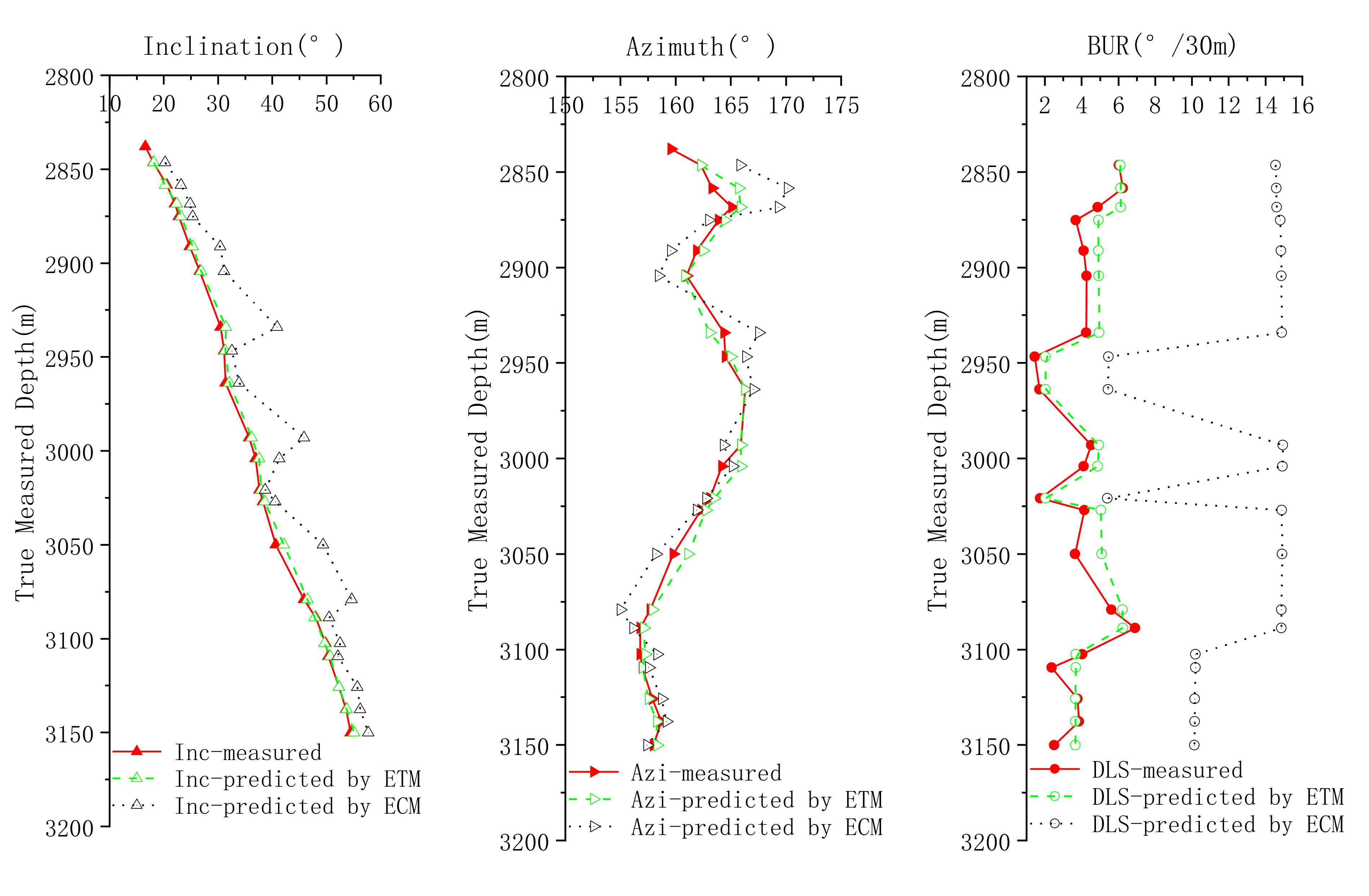
4. Case Calculation and Analysis

A test case is chosen from a shale gas horizontal well in southwest China. The RSBHA is shown in Figure 1 and Figure 2. The known conditions of the test case are listed in Table 1. The wellpath control instructions of RSS and measured wellpath data are shown in Table 2.
The RSBHA mechanical model proposed in this paper is employed to calculate the lateral forces and tilt angles of drill bit at different survey stations, and then, the ETM and ECM are adopted to predict the BURs, inclinations, and azimuths simultaneously. All measured wellpath data and predicted wellpath data are summarized in Table 2 and Figure 7.
It can be seen that when using the ETM proposed, the predicted wellpath data (inclination, azimuth, and BUR) are totally more accurate than those of the traditional ECMs. The average absolute errors of inclination, azimuth, and BUR at each survey station or section are 0.43°, 0.59°, and 0.67°/30 m, respectively. Only a few survey stations or sections have larger errors. Compared to the ECM, the ETM can enhance the BUR prediction accuracy greatly and meet the drilling requirements.
The test case analyses have also showed that the predicted BUR of ECM is always quite larger than the true values. That is why its modified methods use two coefficients to decrease the values [15].
The simulation analyses have also verified that the modified mechanical model of RSBHA in this article can enhance the accuracy of lateral forces and tilt angles of the drill bit, and the modified ETM under the 3D condition could reduce trial calculation times and improve the solution efficiency.

5. Conclusions

In this article, a powerful BUR prediction method for the static push-the-bit RSS is reconstructed and verified by an instance analysis. Some instructive conclusions and understandings are obtained for the development and application of the static push-the-bit RSS.
(1)
When establishing the RSBHA mechanical model by using the beam column method, the steering rib should be considered as an eccentric stabilizer.
(2)
For the beam column between two stabilizers, it should be rearranged into three beam columns, and the two steps of the flexible sub should be considered as virtual supports.
(3)
Under 3D conditions, the total drilling tendency angle should be denoted by inclination tendency angle and azimuth tendency angle to enhance the solution efficiency.
(4)
The ETM to predict the BUR can enhance the wellpath prediction accuracy than those of traditional methods. Its average forecast error of BUR is less than 1°/30 m.

Author Contributions

All the authors conceived and designed the study. Y.S., Z.T. and Z.G. performed the formula derivation, model calculation, and wrote the paper; J.B. and W.L. finished the field application; H.L., Y.X. and Y.L. discussed the model and edited the manuscript. All authors have read and agreed to the published version of the manuscript.

Funding

This research was funded by the China National Natural Science Fund Project (grant number 51674284) and China National Important and Special Project (grant number 2016ZX05022-002).

Acknowledgments

This research was also supported by the Key Laboratory of Unconventional Oil & Gas Development of China University of Petroleum, and Key R&D Program of Shandong Province, China (grant number 2019GHZ001).

Conflicts of Interest

The authors declare that there is no conflict of interests regarding the publication of this paper.

Nomenclature

RSSrotary steerable system
BURbuild-up rate
BHAbottom-hole assembly
RSBHArotary steerable bottom-hole assembly
TPCMthree-point circular method
ECMequilibrium curvature method
ETMequilibrium tendency method
TMDtrue measured depth of a survey station

References

  1. Kenupp, R.; Lourenço, A.; Soltvedt, S.; Thomson, I.; Simoes, G.; Morosov, D.; Andrade, R. The Longest Horizontal Section ever Drilled in an Extended-Reach Well in Brazil. In Proceedings of the Offshore Technology Conference Brazil, Rio de Janeiro, Brazil, 24–26 October 2017. [Google Scholar]
  2. Al Dabyah, A.A.; Zubairi, B.A.; Al Umairin, I.S.; Chima, J.I.; Kunhiveetil, D.; Otaif, H.W. Proper planning supported by latest technology leads to drilling the longest 8.5 in section in an extended-reach well: Case study. In Proceedings of the SPE Annual Technical Conference and Exhibition, Dubai, UAE, 26–28 September 2016. [Google Scholar]
  3. Jerez, H.; Tilley, J. Advancements in powered rotary steerable technologies result in record-breaking runs. In Proceedings of the SPE Latin American and Caribbean Petroleum Engineering Conference, Maracaibo, Venezuela, 21–23 May 2014. [Google Scholar]
  4. Warren, T. Steerable motors hold their own against rotary steerable systems. In Proceedings of the SPE Annual Technical Conference and Exhibition, San Antonio, TX, USA, 24–27 September 2006. [Google Scholar]
  5. Moody, M.; Boonen, P. Borehole quality analysis comparing rotary steerable tools to conventional directional drilling assemblies. In Proceedings of the AADE 2005 National Technical Conference and Exhibition, Houston, TX, USA, 5–7 April 2005. [Google Scholar]
  6. Zhang, Y.; Samuel, R. Analytical model to estimate the directional tendency of point and push-the-bit BHAs. In Proceedings of the SPE Annual Technical Conference and Exhibition, Houston, TX, USA, 28–30 September 2015. [Google Scholar]
  7. Al Dabyah, A.; Biscaro, E.; Mayer, H. New generation of rotary steerable system enables higher BUR and performance. In Proceedings of the SPE Annual Technical Conference and Exhibition, Dubai, UAE, 26–28 September 2016. [Google Scholar]
  8. Johnstone, J.A.; Allan, D. Realizing true value from rotary steerable drilling systems. In Proceedings of the 1999 Offshore Europe Conference, Aberdeen, UK, 7–9 September 1999. [Google Scholar]
  9. Karisson, H.; Brassfield, T. Performance drilling optimization. In Proceedings of the SPE/IADC Drilling Conference, New Orleans, LA, USA, 5–8 March 1985. [Google Scholar]
  10. Karisson, H.; Cobbley, R.; Jaques, G.E. New developments in short, medium, and long-radius lateral drilling. In Proceedings of the SPE/IADC Drilling Conference, New Orleans, LA, USA, 28 February–3 March 1989. [Google Scholar]
  11. Liu, X.S.; He, S.S.; Zou, Y. Study on the geometric build angle rate of steerable motor. Acta Pet. Sin. 2004, 25, 83–87. [Google Scholar]
  12. Sugiura, J. Optimal BHA design for steerability and stability with configurable rotary-steerable system. In Proceedings of the SPE Asia Pacific Oil & Gas Conference and Exhibition, Perth, Australia, 20–22 October 2008. [Google Scholar]
  13. Stroud, D.; Peach, S.; Johnston, I. Optimization of rotary steerable system bottom hole assemblies minimizes wellbore tortuosity and increases directional drilling efficiency. In Proceedings of the SPE Annual Technical Conference and Exhibition, Houston, TX, USA, 26–29 September 2004. [Google Scholar]
  14. Birades, M.; Fenoul, R. A Microcomputer program for prediction of bottom hole assembly trajectory. SPE Drill. Eng. 1988, 3, 167–172. [Google Scholar] [CrossRef]
  15. Su, Y.N. A method of limiting curvature and its application. Acta Pet. Sin. 1997, 18, 110–114. [Google Scholar]
  16. Shi, Y.C.; Guan, Z.C.; Zhao, H.S.; Huang, G.L. A new method for build-up rate prediction of bottom-hole assembly in well drilling. J. China. Univ. Pet. Nat. Sci. Ed. 2017, 1, 85–89. [Google Scholar]
  17. Panayirci, H.M.; Brands, S.; Houette, O. Selection of optimum bottom hole assembly configuration using steering prediction modeling. J. Nat. Gas Sci. Eng. 2015, 27, 757–762. [Google Scholar] [CrossRef]
  18. Wang, H.; Guan, Z.C.; Shi, Y.C.; Liu, Y.W.; Liang, D.Y. Drilling trajectory prediction model for push-the-bit rotary steerable bottom hole assembly. Int. J. Eng. 2017, 11, 1800–1806. [Google Scholar]
  19. Wang, H.; Guan, Z.C.; Shi, Y.C.; Liang, D.Y. Study on build-up rate of push-the-bit rotary steerable bottom hole assembly. J. Appl. Sci. Eng. 2017, 3, 401–408. [Google Scholar]
  20. Shi, Y.C.; Teng, Z.X.; Bai, J.; Guan, Z.C.; Liu, Q.C.; Wang, H.; Fan, Z.B. Improved mechanical model of the static push-the-bit rotary steerable bottom-hole assembly. J. China. Univ. Pet. Nat. Sci. Ed. 2018, 5, 75–80. [Google Scholar]
  21. Li, Z.F.; Zhao, J.H.; Li, J.Y. Mathematical models for 3D analysis of rotary steering bottom hole assembly with small deflection. Acta Pet. Sin. 2004, 25, 84–88. [Google Scholar]
  22. Hong, D.F.; Tang, X.P.; Su, Y.N.; Sheng, L.M.; Dou, X.R. Generalized beam-column method for non-continuous rotary steering drilling of bottom-hole assembly. Acta Pet. Sin. 2014, 35, 543–550. [Google Scholar]
  23. Tang, X.P.; Su, Y.N.; Ge, Y.H.; Sheng, L.M.; Li, T.J. BHA mechanical analysis for rotary steering drilling system. Mech. Eng. 2013, 1, 55–59. [Google Scholar]
  24. Bai, J.Z.; Su, Y.N. Deviation Control in Direction Drilling; China Petroleum Industry Press: Beijing, China, 1990. [Google Scholar]
  25. Ajibose, O.K.; Wiercigroch, M.; Akisanya, A.R. Experimental studies of the resultant contact forces in drill bit-rock interaction. Int. J. Mech. Sci. 2015, 91, 3–11. [Google Scholar]
  26. Tang, X.P. Non-uniform stiffness beam-column theory and its application. Mech. Eng. 2011, 5, 12–15. [Google Scholar]
Figure 1. A typical static push-the-bit RSBHA.
Energies 13 04847 g001
Figure 2. Continuous beam column model of the RSBHA.
Energies 13 04847 g002
Figure 3. Force analyses of the beam columns related to the steering rib.
Energies 13 04847 g003
Figure 4. Force analyses of the beam columns related to the flexible sub.
Energies 13 04847 g004
Figure 5. Drilling tendency analysis.
Energies 13 04847 g005
Figure 6. Solution procedure of the ETM.
Energies 13 04847 g006
Figure 7. Measured wellpath data vs. predicted wellpath data.
Energies 13 04847 g007
Table 1. Known conditions of the test case.
D c 1 /mm190.0 d 1 /mm55.0 L 1 /m0.6 D b /mm215.9
D c 2 /mm190.0 d 2 /mm55.0 L 2 /m2.4 D s 1 /mm213.0
D c 3 /mm178.0 d 3 /mm57.2 L 3 /m0.7 D s 2 /mm213.0
D c 4 /mm127.0 d 4 /mm57.2 L 4 /m1.2 I b 0.035
D c 5 /mm178.0 d 5 /mm57.2 L 5 /m4.5
D c 6 /mm178.0 d 6 /mm57.2 L 6 /m15.0
Table 2. Measured wellpath data vs. predicted wellpath data.
TMD
(m)
dL
(m)
Measured ValuesWellpath Control InstructionsPredicted Values by ETMPredicted Values by ECM
INC
(°)
AZI
(°)
BUR
(°/30 m)
INC
(°)
AZI
(°)
BUR
(°/30 m)
INC
(°)
AZI
(°)
BUR
(°/30 m)
2838.04/16.61159.59/60 kN, 100%, 30°//////
2846.518.4718.11162.296.0318.14162.296.1120.21165.8414.55
2858.4211.9120.57163.296.2520.26165.726.1223.20170.1414.59
2868.4410.0222.06165.094.8722.39165.886.1324.86169.3214.61
2875.276.8322.76163.893.6780 kN, 100%, 345°23.15164.464.9125.33163.0114.81
2891.2115.9424.79161.894.1125.31162.494.9230.41159.5414.85
2904.4513.2426.63160.994.2626.91160.824.9331.14158.4414.86
2934.0929.6430.5164.394.2580 kN, 100%, 15°31.42163.084.9640.89167.5314.89
2946.7712.6831.11164.491.4580 kN, 33%, 30°31.30165.002.0432.57166.355.45
2963.7917.0231.38166.291.7132.12166.262.0433.88167.045.44
2992.9629.1735.77165.894.5280 kN, 100%, 355°36.18165.924.9445.85164.3514.94
3004.0811.1236.91164.194.1037.58165.924.8841.28165.1514.93
3020.8716.7937.62163.091.7480 kN, 33%, 330°37.96163.492.0338.71162.745.41
3027.076.2038.32162.294.1480 kN, 100%, 345°38.64162.765.0440.60161.8914.89
3050.0422.9740.61159.793.6442.14161.115.0849.38158.2214.90
3079.2229.1845.88157.695.6260 kN, 100%, 345°46.53157.906.2354.63154.9914.87
3088.839.6147.99156.796.9047.83157.106.2450.50156.1314.86
3102.5313.7049.83156.794.0380 kN, 66%, 15°49.63157.253.6752.50158.3110.20
3109.506.9750.36156.992.3750.66157.023.6752.12157.5610.20
3125.7916.2952.29157.893.7852.31157.523.6655.70158.7310.16
3137.7411.9553.61158.693.8553.72158.273.6656.20159.1510.15
3150.2212.4854.49157.992.5080 kN, 66%, 345°55.10158.303.6657.69157.4010.14
Average absolute error/ Maximum absolute error0.43/1.530.59/2.430.67/1.444.10/10.391.82/6.858.38/11.26
Note: (1) TMD, INC, and AZI denote the measured depth, the inclination, and the azimuth of at a survey station; dL denotes the measured depth increment of a survey interval. (2) The push-the-bit RSS is accustomed to use a set of wellpath control instruction with the WOB, the relative steering force and the tool-face angle. For example, “90 kN, 100%, 345°” means that the WOB is 90 kN, and the relative steering force is 100% of the maximum value (22.5 kN), and the high side tool face angle is 345°.

