Abstract
In ground-source heat-pump systems, the heat exchange rate is influenced by various design and operational parameters that condition the thermal performance of the heat pump and the running costs during exploitation. One less-studied area is the relationship between the pumping costs in a given system and the heat exchange rate. This work analyzes the investment and operating costs of representative borehole heat-exchanger configurations with varying circulating flow rate by means of a combination of analytical formulas and case study simulations to allow a precise quantification of the capital and operational costs in typical scenario. As a conclusion, an optimal flow rate minimizing either of both costs can be determined. Furthermore, it is concluded that in terms of operating costs, there is an operational pumping rate above which performance of geothermal systems is energetically strongly penalized.
1. Introduction
The thermal efficiency of a borehole heat exchanger is characterized by its thermal resistance, i.e., the thermal resistance between the circulating fluid and the borehole wall. This parameter originally was defined by Mogenson [1] and widely analyzed by Eskilson [2] and Hellström [3] where the thermal behavior of geothermal heat exchangers is modelled on the basis of the following key parameters:
- (i)
- the thermal conductivity of the ground (),
- (ii)
- the thermal resistance of the borehole heat exchanger (),
- (iii)
- the undisturbed ground temperature (), and,
- (iv)
- the injection (or extraction) of heat ratio (thermal power input) (q) (that depends on flow rate and temperature gap of working fluid).
The (effective) borehole resistance () should be as low as possible since it has direct relationship with the thermal efficiency of the heat exchanger. The higher borehole thermal resistance, the lower heat transferred between the heat carrier fluid and the ground. Hence, by increasing the borehole thermal efficiency (a smaller borehole thermal resistance, ), the average working fluid temperature under the same thermal power ratio is decreased. Therefore, by improving the thermal efficiency of the borehole, either the number of drilling meters can be reduced (while maintaining the thermal efficiency of the heat pump) or the average working fluid temperature of the borehole can be improved (while improving the thermal efficiency of the heat pump, maximizing the system efficiency). This parameter, , should consequently be optimized to the lowest possible value.
The thermal resistance of the borehole is mainly affected by the following key parameters:
- –
- Properties and flow rate of the fluid through the heat exchanger,
- –
- Diameter of the geothermal borehole,
- –
- Geometry and materials of the heat-exchanger pipe, and,
- –
- Grouting material.
Most of these key parameters depend on borehole design. However, the flow rate can be to a certain degree controlled during the operation phase taking into account that the pumping requirements of a Ground-Source Heat Pump (GSHP) should be kept as low as possible to minimize losses. It should be noted that these hydraulic losses may be significant (between 4% to 21% of total system consumption [4], especially at high flow rates), increasing electricity consumption, and, substantially penalizing the overall performance. On the other hand, borehole heat resistance depends on the fluid flow rate and, thus, borehole thermal resistance and pumping losses are interrelated. Hence, to seek a compromise between increasing of the thermal efficiency of the borehole and reducing of the hydraulic losses in the GSHP system is reasonable.
There are numerous publications dealing with the thermal resistance of borehole heat exchangers [5] either using finite element numerical techniques [6,7] or based on analytical solutions of the heat exchange problem with different more or less realistic simplifying assumptions [8,9,10]. The latter are easily applied but can only to a limited type of pipe geometries and under certain conditions. These studies show that factors such as an increased thermal conductivity of the fluid conducting pipes and grout material or a closer distance of these pipes to the borehole wall will improve the thermal performance [11]. In [12] these claims were subsequently demonstrated in several field tests. Other studies focused on the impact of the heat carrier fluid flow rate on the borehole resistance (showing a strong decrease with decreasing flow rate [13]), on the thermo-hydraulic performance of a specific geometry GHE [14] or of a particular installation [15]. Even [16] proposes an analytical solution basing an entropy minimization technique in order to calculate the optimal flow rate but this analysis do not consider the heat-pump operation.
The evaluation of GSHP investment cost has been carried out in several studies for specific buildings or facilities, mainly compared to other renewable energies or HVAC technologies. For example, in [17] is carried out an energetic and economic analysis comparing the traditional system (boilers, chimneys and split system air conditioners) with innovative systems: GSHP, GSHP coupled with thermal solar collector, hybrid boiler-GSHP, GSHP coupled with photovoltaic cells. Operating costs are analyzed in bibliography by comparison with other systems, mainly economic evaluation of a GSHP system versus an air source heat pump [18] or evaluation of strategies to minimize costs in hybrid systems [19]. Studies show that improving GSHP system efficiency is usually done by oversizing the BHE field [20] but it is also possible to increase the efficiency decreasing the borehole thermal resistance as described above. In this context, the studies analyzed show how to improve the efficiency of the system by comparing different BHE configurations [21,22]. The aim of this work is not to characterize the best BHE configuration but to analyze the impact of working fluid flow rate on total costs (execution and operation expenditures).
Despite the background described, no studies have been found such this holistic sensitivity analysis of the impact of the heat carrier fluid flow rate on the thermal efficiency of the borehole and its reflection in the execution and operation costs. By means of a reliable analytical tool, previously validated by experimental results, an extensive fluid flow rate evaluation on the thermal efficiency of the borehole is carried out, under different design parameters (conductivity of the borehole materials, pipe and grout).
The validation of the analytical tool from experimental data has been done by means of Thermal Response Tests or TRTs [23,24], a widely accepted method [25,26] to determine the main parameters that define the thermal behavior of a borehole: the thermal resistance of the borehole () and the thermal conductivity of the ground ().
A scenario is then presented to evaluate this thermal efficiency impact considering the economic constraints, both in execution (length of borehole required due to thermal resistance of the borehole) and in operation (pumping requirements and geothermal heat-pump performance). The study is focused on a single U-tube configuration, first analyzing the influence of the flow rate on the thermal borehole resistance and the pressure losses and then conducting a quantification of the impact of the flow rate on drilling and operation costs in a borehole field of 9 single U-tube in two scenarios: constant length and constant efficiency of the BHEs.
2. Methodology
As explained in [27], the theoretical basis for the thermal calculation of BHEs was established long ago (see [3] for the most comprehensive treatment of the subject so far).
In broad terms, the total thermal resistance () between the pipe and the ground at a large distance from the pipe center, mediates the relation between the heat flow q and the temperature difference between the fluid inside the pipe () and the temperature in the surrounding soil ():
When the steady flow (or steady flux) conditions are established-after some time-the total heat resistance can be split up into two terms given by:
where is the soil resistance, mainly related to the ground thermal conductivity () and other soil-related factors and is the—constant—borehole resistance, given mainly by borehole characteristic parameters.
At long enough time, can be well approximated by simple formulas like the line, cylinder or finite line approximations—as discussed [3,28], while is a complex function depending on its geometric features, material properties, internal flow conditions and composite region (grout) conductivity conditions, more difficult to calculate.
2.1. Analytical Tool to Evaluate Thermal Efficiency of BHE According to Hydrogeological Conditions, Geometric Characteristics and Material Properties
According to the established theoretical methodology, heat transfer across borehole pipe is divided into different components which can be treated separately to model the local, steady-state heat conduction problem between the heat carrier fluid in the pipes and the adjacent surrounding ground. All these equations have been integrated into a comprehensive analytical tool that assesses the effective thermal resistance of the borehole. This work is focused on the component of the tool that allows isolation of the influence of fluid flow on heat transfer and pressure losses in a given geometrical configuration (single U-tube). The results are subsequently compared to the experimental results of our TRT tests to assess the validity of the model.
Following [3], this assessment can be characterized by means of the effective borehole resistance () defined as the thermal resistance between the wall borehole temperature and the average temperature inside the borehole heat exchanger. The average temperature is defined as the average between the inlet and outlet temperature at borehole. This effective borehole heat resistance is exactly what a Thermal Response Test (TRT) seeks to determine experimentally from a given real borehole.
More precisely, the effective borehole resistance is defined as:
Here it is important to note that represents the average fluid temperature inside the BHE, denotes the temperature in the ground at the distance corresponding to the borehole radius and is the average thermal power heat ratio during the thermal test.
The analysis carried out by the tool to calculate the effective borehole resistance is done considering a simplified model for the counter-flow heat exchange between the downward and upward flows and solving the corresponding coupled equation system that involves the z-evolution of the temperatures in both legs (the thermal evolution along the pipe (z axis) of single U-tube for each of the two “legs” (pipes) that compose it).
2.1.1. Heat Transfer Assessment
The pipe resistance () is usually split into three parts [3]:
The first term () relates with the resistance to heat transfer due to the conductivity of the material from which the pipe wall is made of. For a cylindrical wall with inner radius and outer radius the relation is given by:
Please note that here is now the conductivity of the pipe material. In the case of conventional polyethylene 100 (PE100) plastic pipes its value is around 0.4 W/(mK) (see new edition of guideline VDI 4640-2 (VDI 4640 is a widely respected industry standard in Germany and neighboring countries, first published in 1998, and now comprising 5 parts for different aspects of shallow geothermal energy.), published in May 2015).
The resistance term quantifies the resistance to heat transfer caused by a non-ideal contact between the outer pipe wall and the surrounding grout. Some authors [3,29,30] have discussed what could be reasonable values for , but there is no general formulation for this term. In most BHE studies, is not considered and just included as one of the many sources of uncertainty in the analysis of thermal resistances.
Finally, the term is given by the heat transfer conditions due to the forced convective process between the fluid at a temperature and the internal wall of the pipe. This process is conventionally represented by the non-dimensional Nusselt number, for which many correlations and studies have been made since long ([31,32]). The relationship between the resistance and the Nusselt number is given by:
being the thermal conductivity of the heat transfer fluid (usually water or a glycol and water mixture).
The Nusselt number () itself depends on different factors. According to the most accepted correlations, mainly on the Reynolds number (), the Prandlt number () and the inner radius of the pipe to borehole deep ratio of the borehole (), hence:
For long depth boreholes (), is close to zero and does not have influence on the process. The quantities appearing in the correlation are hence the basic fluid properties (viscosity, , heat capacity, , and density, , which are temperature and pressure dependent) and the volume flow, .
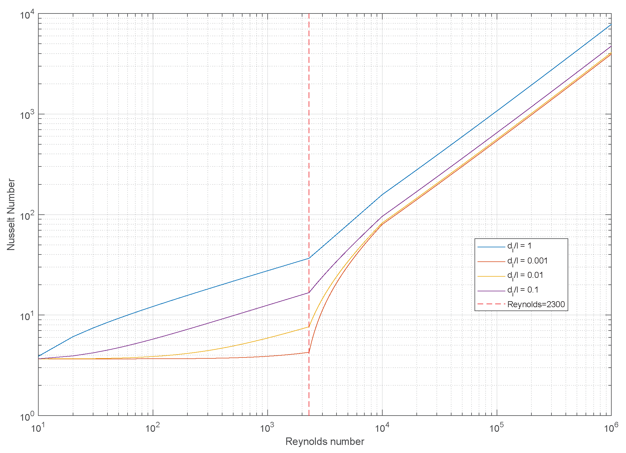
For the present analysis, the correlations and fluid property functions were taken from reference [33], the VDI atlas published in 2010. Figure 1 summarizes the resulting Nusselt number as a function of Reynolds number and a Prandtl number of 5.43 (which corresponds to water at atmospheric pressure and temperature of 30 C), for circular section pipes with different internal radius to deep ratios according to the implementation of the correlations recommended by VDI Heat Atlas [33]. Each curve is representative for a different diameter, d, to length, l, ratio (in our case, it can be assimilated to inner pipe radius to borehole deep ratio), being the red curve the one that represents the long pipe scenario . As can be seen, in this case the Nusselt number in the laminar flow condition () is basically constant. There is a steep increase of in the transition regime ( between 2300 and around ) and finally an increase with a constant slope (in logarithmic representation) is found within the turbulent flow regime (). The blue curve would correspond to a “very short pipe” scenario with a radius to H relation of 1, while the red curve at the bottom depicts the result for a very long pipe, were is about zero.
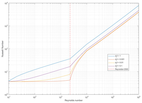
Figure 1.
Nusselt number as a function of Reynolds number.
2.1.2. Hydraulic Assessment
In this analytical tool, within a framework for pressure losses calculation in arbitrary geometries, the calculation of pressure loss caused by a given flow in a circular section unit pipe (based on the Darcy law) using the Gnielinski algorithm have been implemented (as published in [33], Chapter L).
Following the traditional Darcy–Weisbach analysis, the pressure loss through a pipe of a given length L, is given by:
where is the mean cross-section fluid velocity in the circular section pipe under consideration, the inner diameter of the pipe and is generally known as the drag or friction coefficient, which depends on several factors such as the Reynolds number of the flow, the geometry of the flowing channel and the internal surface roughness characteristics.
It is important to state that—to standardize and be able to compare different design solutions—our analysis will be referred to the pipe unit length (L) and thus:
is the pressure drop per unit length of BHE (). From this, the ideal hydraulic power per unit of pipe length spent to meet the pumping needs, can be calculated in an easy way:
where
- is the hydraulic power per unit of length (W/m),
- is the volume flow (m/s), and,
- is the differential pressure (Pa/m) [from Equation (8)]
Friction Coefficient and Pumping Losses Calculation
In the case of a circular pipe, the correlation recommended in the VDI atlas [33] and valid for smooth pipes establishes that the friction factor ():
And the Reynolds number:
being, and .
2.2. Capital and Operating Costs
Costs related to ground-source heat-pump installation can be classified into three main groups: investment costs, operating costs and decommissioning and disposal costs. First group refers to how much it cost to install the geothermal system, i.e., the cost of drilling, trenching, installing pipes, hydraulic components, circulation pump and heat pump. Operating costs are the annual costs incurred during operation such as electricity bills or maintenance work. Finally, decommissioning costs include scrapping of heat pump, disposal of refrigerants or restoration of land due to the boreholes.
In this article, the installation costs of drilling and equipping the geothermal borehole at designed depth and the energy operating costs (the electricity consumption of the heat pump during its operating time and the electricity consumption of the circulation pump necessary to overcome hydraulic losses) are analyzed for different scenarios in a typical geothermal installation.
According [34], the Capital Expenditures (CAPEX) (€/year) can be calculated using the following expression:
where
- is the total cost of an equipped borehole per drilled meter (€/m),
- n is the number of boreholes,
- L is the borehole depth (m), and,
- N is installation amortization period (years).
In this case, only the capital expenditures related to the borehole field are taken into account as these are the only ones affected by the thermal efficiency of the borehole.
In addition, the Annual Energy Operating Costs (OPEX) (€/year):
where
- is the Annual energy Operating Cost of Heat Pump (€/year)
- is the Annual energy Operating Cost of Circulating Pump (€/year)
- is the Heat-Pump electrical hourly consumption (kW),
- is the Circulation Pump electrical hourly consumption (kW),
- h is the number of operating hours per year, and,
- is the electricity cost (€/kWh).
To quantify these costs, hydraulic losses must be calculated based on the characteristics of the BHE using an analysis tool that allows a thermal and hydraulic evaluation of the borehole.
3. Experimental Validation
To validate the tool and the conclusions obtained from the analytical study, several thermal tests (called Thermal Response Test, or TRT) were performed with a constant and controlled heat injection at different flow rates to allow the thermal transfer in the borehole to be characterized.
The methodology used in these thermal tests is described in [35] and highlights the importance of a strict thermal heat injection control (by means of a PID). In this way, more precise results are obtained than in the traditional methodology, in which no control of thermal injection is carried out, being limited only to the generation of a constant heat pulse that does not take into account thermal losses of the connecting pipes and the thermal influence of the fluctuating outdoor temperatures.
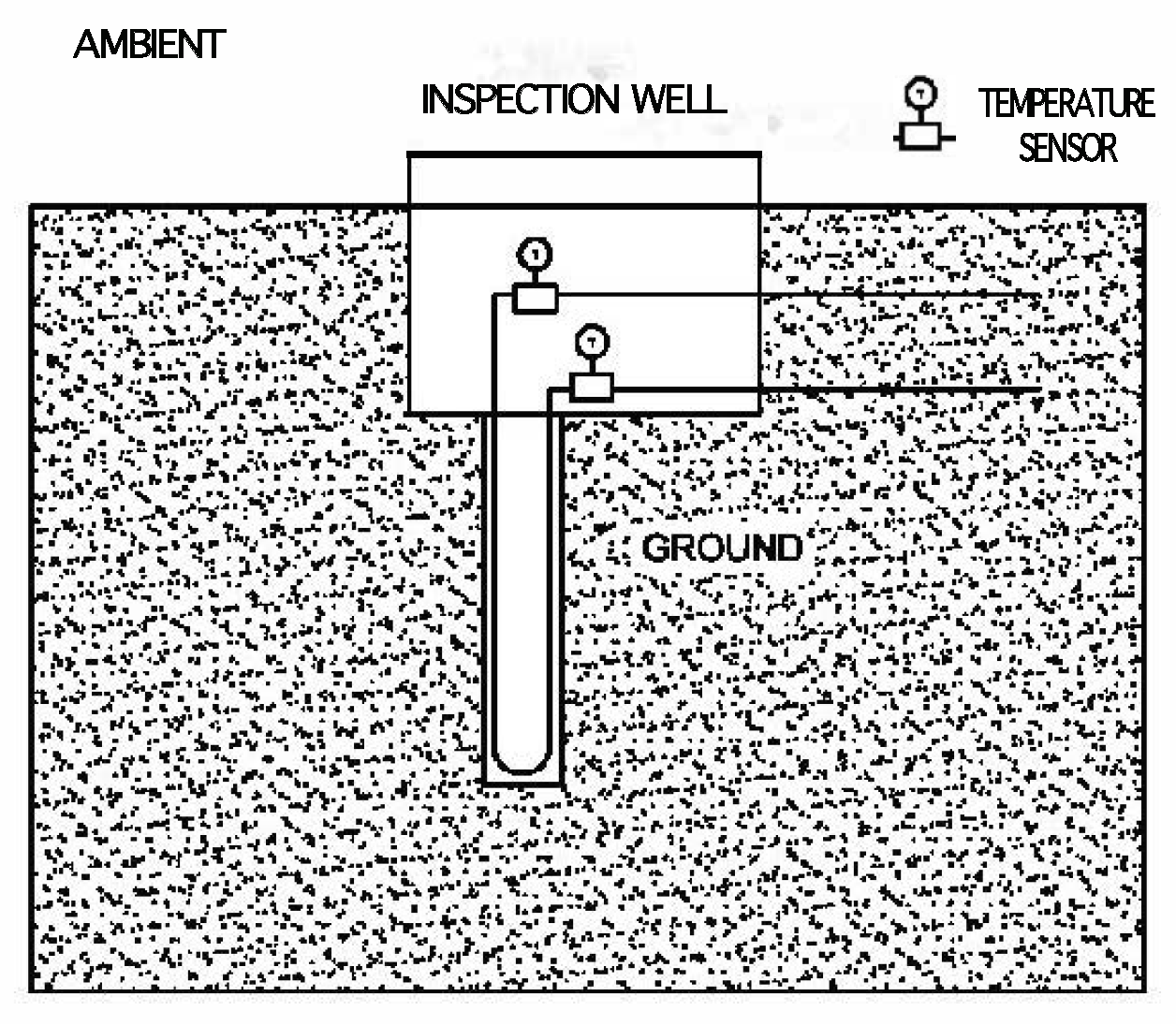
The experimental validation was carried out by means of 3 thermal tests (TRTs) on a single U-tube borehole heat exchanger installed at Universitat Politècnica de València (see Figure 2 that shows the position of the temperature sensors at inlet and outlet of the borehole).
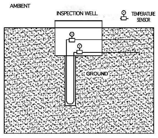
Figure 2.
Scheme of the single U-tube borehole with temperature sensors position.
3.1. Experimental Data
Borehole characteristics are 15 m deep and diameter of iron casing 126/101 mm equipped with a PE-Xa probe, 32 mm of diameter and 2.9 mm thick, and filled with a commercial thermal grout. Table 1 summarizes all technical parameters of the borehole, which are then used as input parameters to the analytical tool.

Table 1.
Parameters of single U-tube borehole.
The thermal tests were performed at the geothermal laboratory test site located inside the Universitat Politècnica de València campus. All the information on the description of the installation is provided in Chapter 2.1 of Reference [35]. TRTs were carried out with different thermal power rate and fluid flow rate and their main parameters are indicated in Table 2.

Table 2.
Main test parameters.
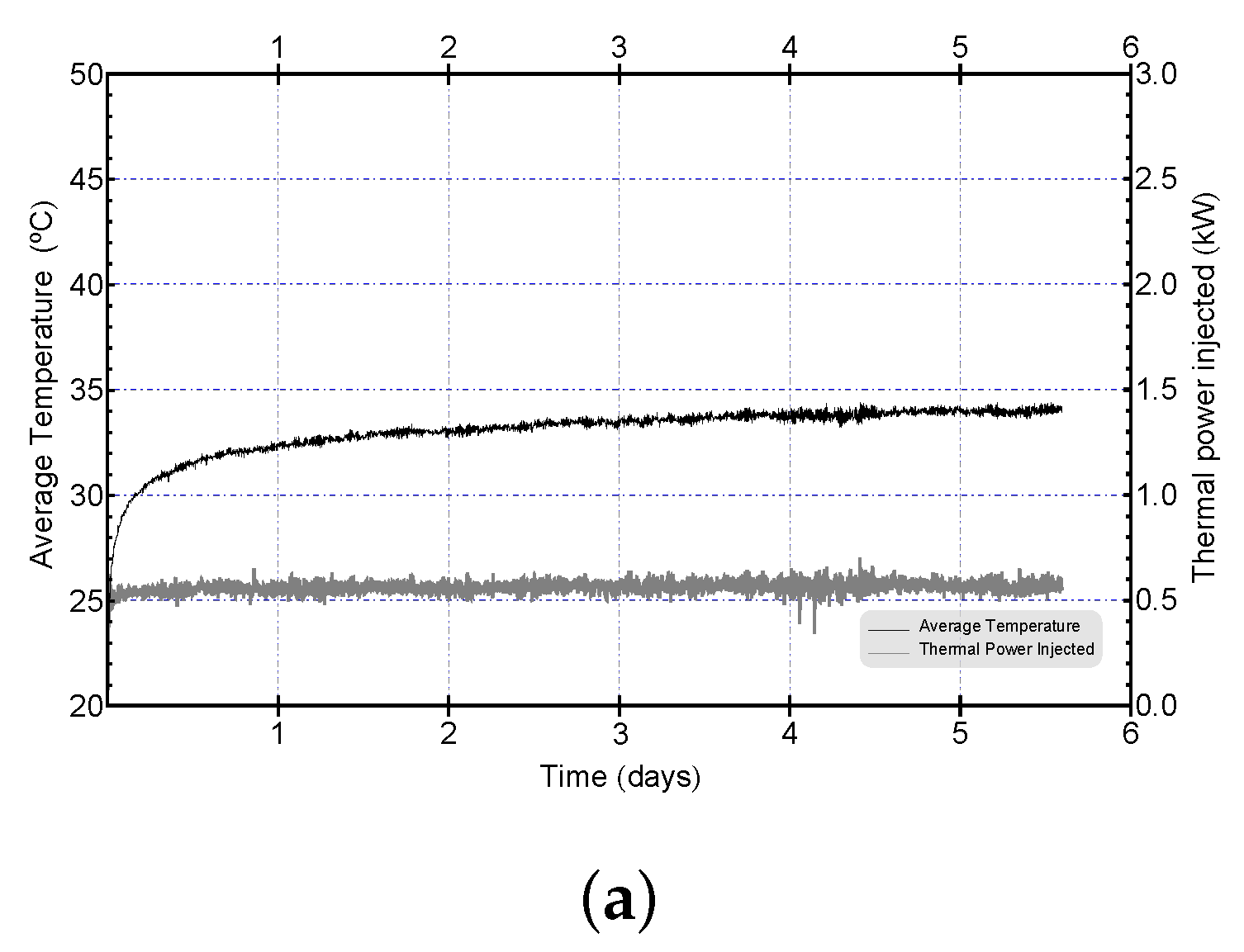
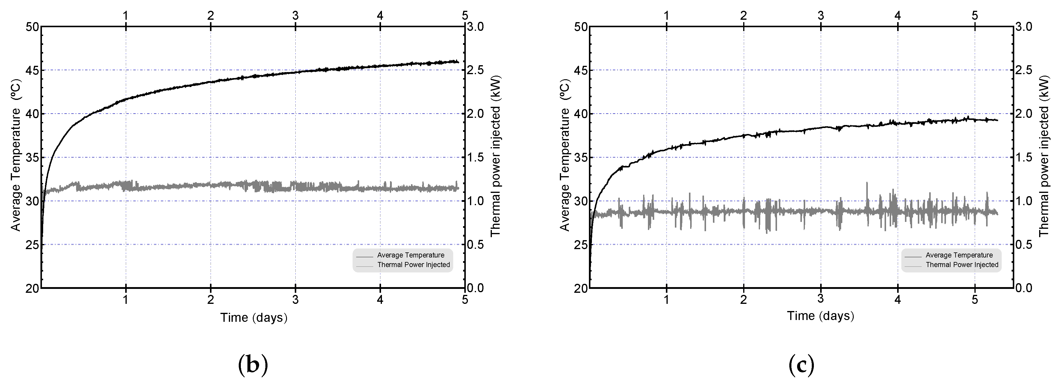
The thermal test duration was variable but longer than 100 h. Test were performed, for three different Reynolds numbers: Test 1 under laminar flow conditions, Test 2 in the boundary between laminar and turbulent flow and Test 3 under turbulent flow in order to analyze Reynolds influence in borehole thermal resistance. Both the installation for carrying out the thermal tests and its procedure are thoroughly described in [36].
The raw temperature data logged during the thermal test (average temperature between borehole inlet and outlet sensors-see Figure 2 and thermal power injection) of each TRT carried out is shown in Figure 3.
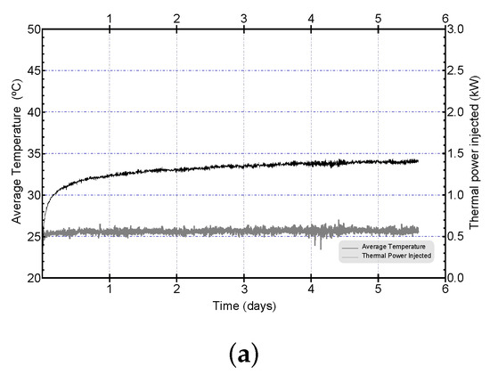
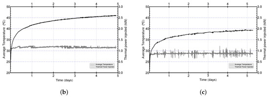
Figure 3.
Average Temperature (in black color) and Thermal Power injected (in grey color) (a) Test 1; (b) Test 2; (c) Test 3.
3.2. Comparing Results
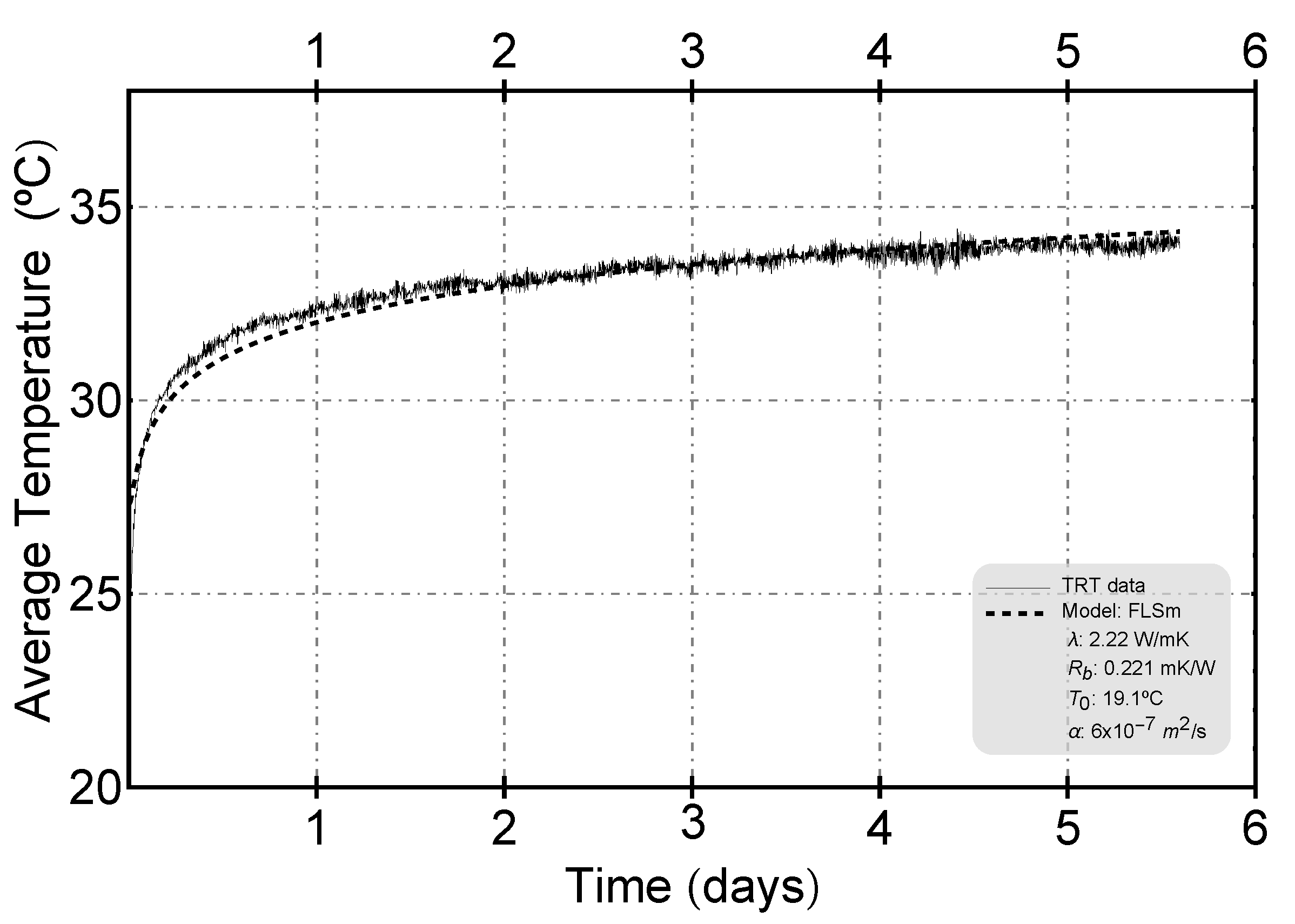
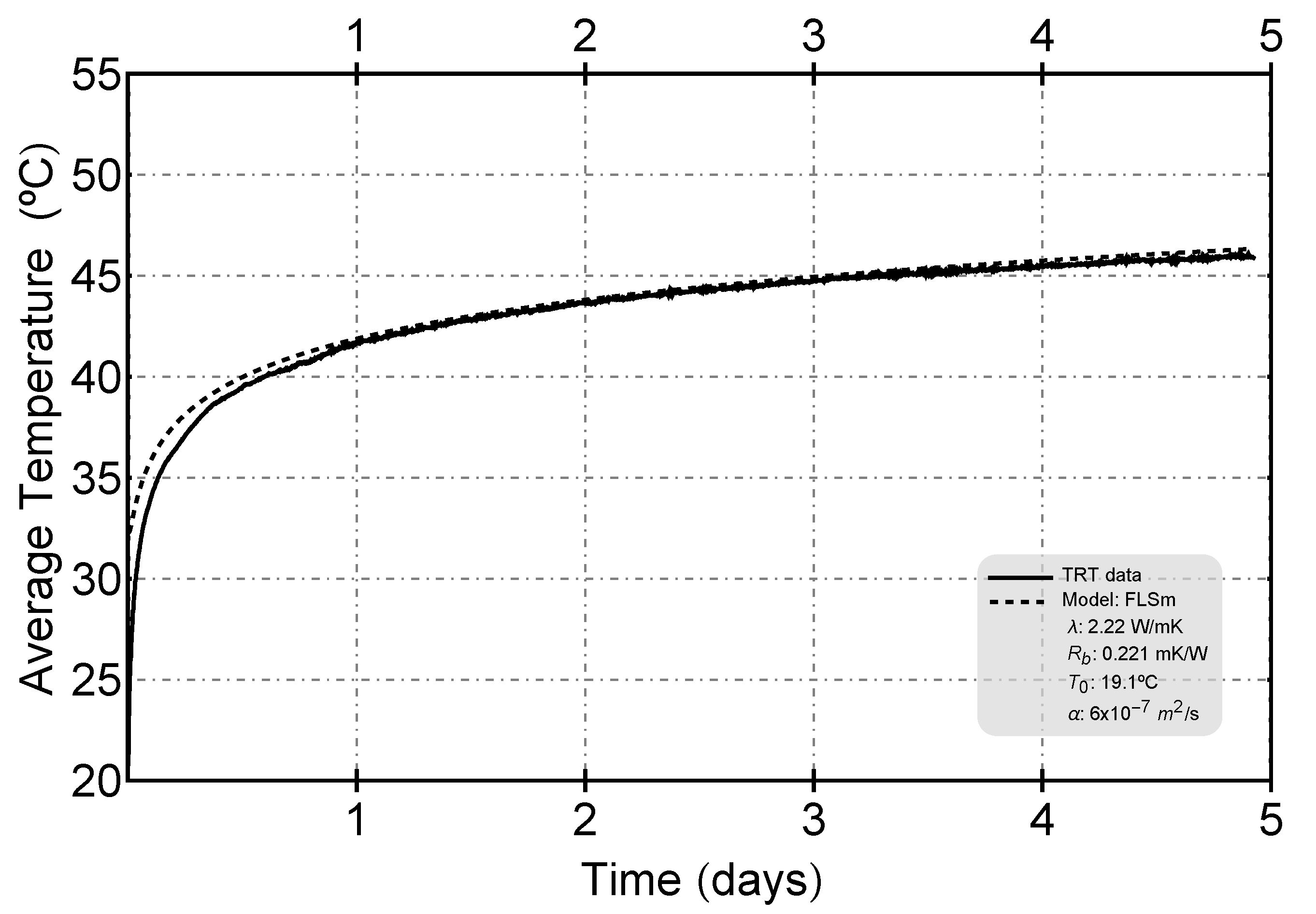
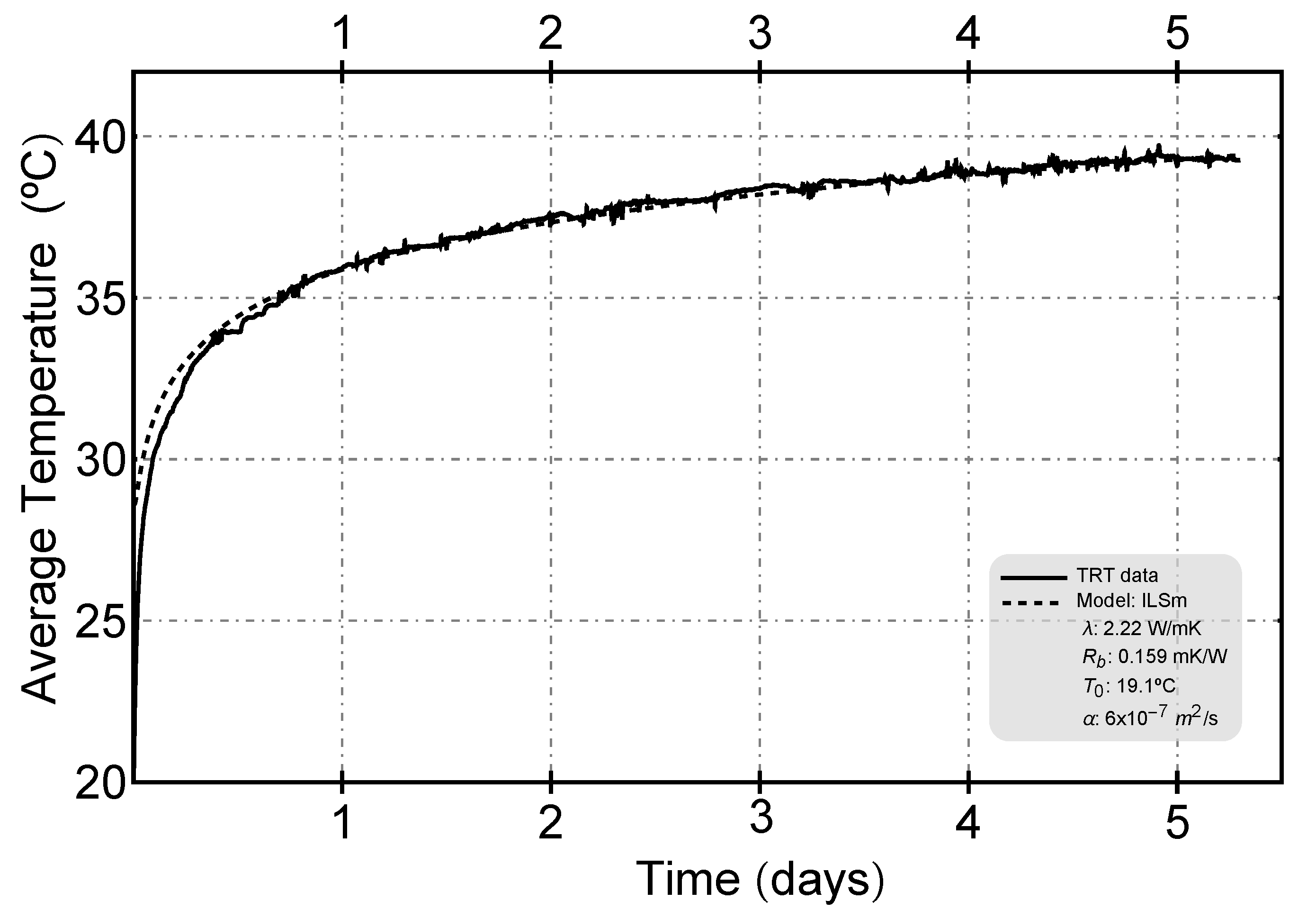
The procedure used for the analysis of the TRTs is explained in detail in [37] and the parameters thermal conductivity of the ground (), borehole thermal resistance (), undisturbed ground temperature () and ground thermal diffusivity () are drawn by means of a method of adjustment (emplsqurvefit) to the main models (Infinite Line Source Model—ILSm—Finite Line Source Model—FLSm—and Finite Cylindric Source Model—FCSm), using the Levemberg–Marquardt algorithm implemented in Matlab©.
The geological setting of the borehole field corresponds to continental alluvial sediments like sands, silts, conglomerates, peat deposits, etc., (Quaternary deposits). Sediments are related to the activity of major river (Turia) and small ravines that have influenced the geomorphology of the Valencian region during the Quaternary [38]. The hydrogeological regime in this area was described in [37]. The area has been characterized with a low estimated Peclet number [37]. For this reason, the possible influence of the groundwater flow has not being considered in the models applied.
The comparison between the experimental results and the model data is presented below, by selecting in each experiment the model (ILSm, FLSm or FCsm) that yields the least Mean Squared Error (see Figure 4, Figure 5 and Figure 6). As can be seen, in the case of the cylindrical model, no adjustment was obtained with the lowest Mean Squared Error.
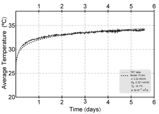
Figure 4.
Fitting model of Test 1.
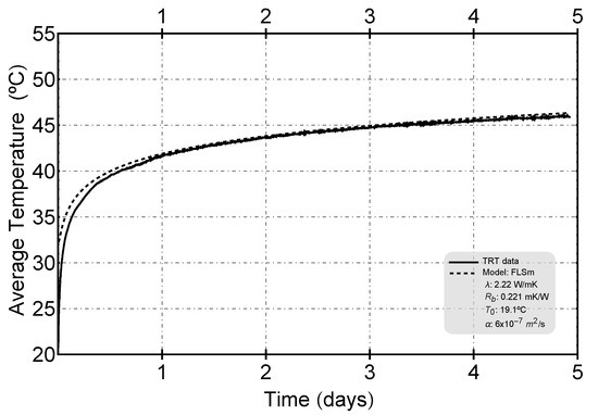
Figure 5.
Fitting model of Test 2.
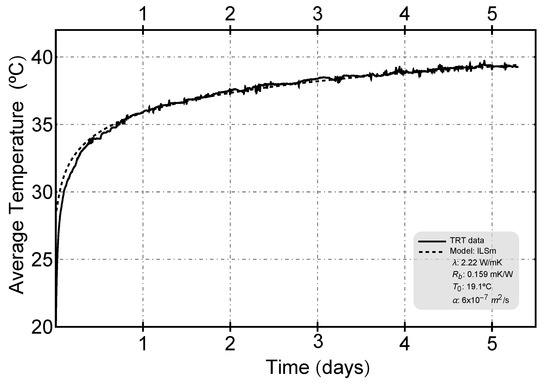
Figure 6.
Fitting model of Test 3.
On the other hand, to build the analytical tool, the analytical formulas described in the previous subsection were implemented as a collection of Mathematica© [39] functions that allow a flexible and general access to a variety of tools to analyze and visualize results. The resulting graphs for the optimization analysis of single U-tube are shown in the next section.
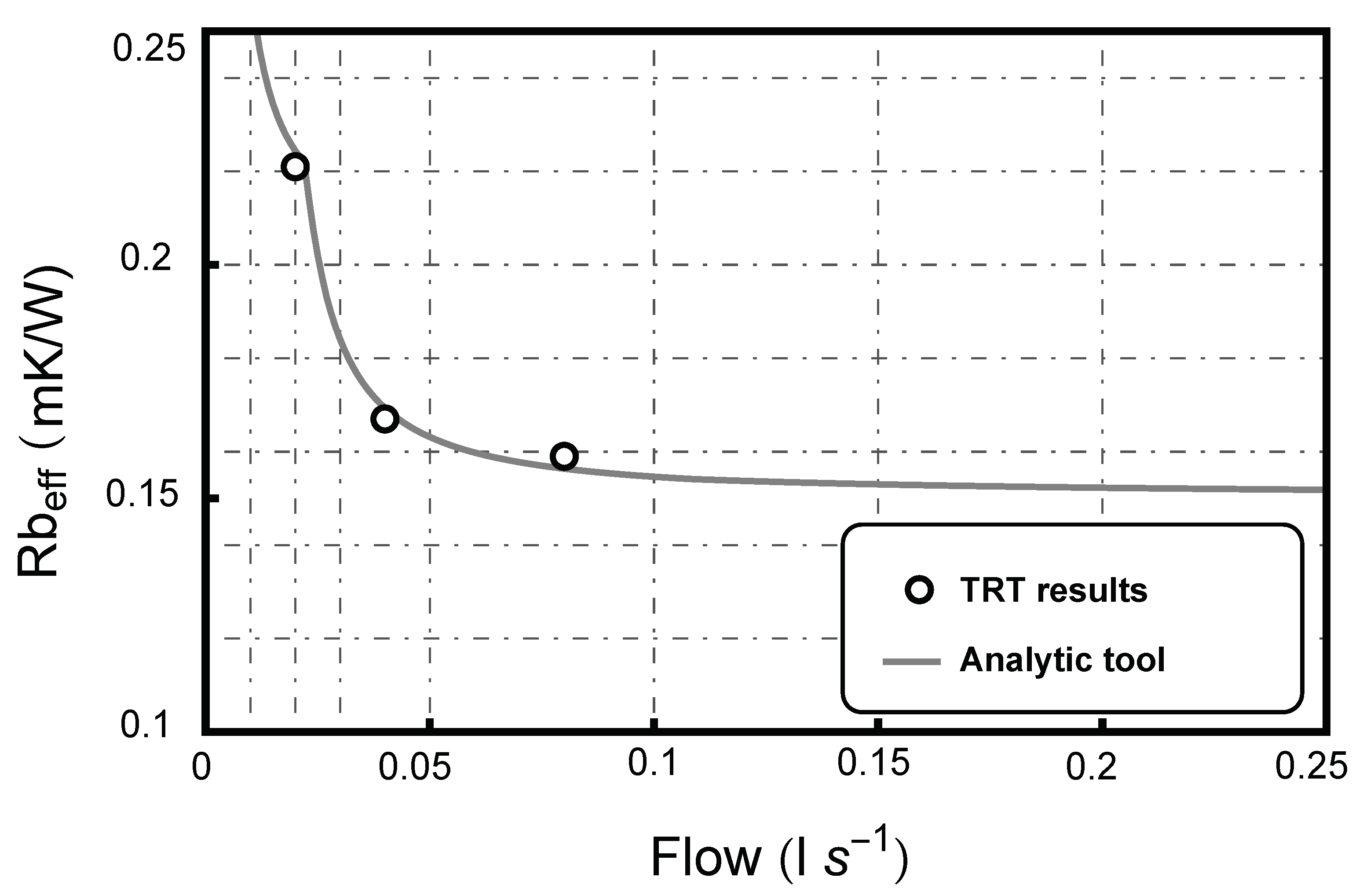
Figure 7 shows the good correlation between the experimentally determined borehole resistances and the predicted values. The results correspond to the standard PE-100 plastic pipe single U-tube BHE of our facility at UPV measured at three different volume flows (ranging from laminar to highly turbulent). The individual dots (○) represent the experimental data (from TRT tests) while the continuous curve represents the calculated values at any flow rate.
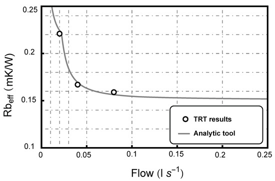
Figure 7.
Flow influence on Thermal Borehole Resistance () [analytical and experimental data].
Table 3 shows the results of the experimental tests (from adjustments shown in Figure 4, Figure 5 and Figure 6) and compares them with the results obtained by the analytical tool for the same characteristics of each thermal experiment. As it can be observed, the values of borehole thermal resistance obtained by means of the analytical tool predict with considerable accuracy the values obtained by the experimental analysis, which justifies the robustness of the results obtained with the analytical tool for the optimization analysis detailed in the following section.

Table 3.
TRT results and comparison.
4. Optimization Assessment
The methodology explained in Chapter Section 2 was implemented in the framework of European projects GEOCOND (Further information at https://geocond-project.eu/) and GEO4CIVHIC (Further information at https://geo4civhic.eu/) to allow a general setting for the optimization of materials and geometrical configurations of BHEs. This methodology is used here to calculate the effective borehole thermal resistance () and the hydraulic parameters (pressure losses) in a single U-tube borehole configuration to characterize the installation’s operating costs analyzing their mutual influence. First, the influence of the flow rate on the thermal borehole resistance and the pressure losses in a single U-tube borehole are studied analytically through the tool. This analysis is then extended to a combined study of the influence of the conductivity of the materials (pipes and grout). Subsequently, a case study of a typical geothermal installation is carried out to quantify the impact of the flow rate on drilling and the operating costs (based on the electricity consumption of the heat pump and the circulation pump) in two limiting scenarios, constant length and constant efficiency of the BHEs.
4.1. Thermal Resistance and Pressure Losses Analysis by Means of Analytic Calculations
Once the results obtained by means of the analytical tool have been validated experimentally, the following analysis has been carried out: the influence of the fluid flow rate on pressure losses per meter of borehole has been calculated by the tool in order to subsequently show the relevant correlation between the pressure drop in the borehole and the thermal efficiency of the borehole.
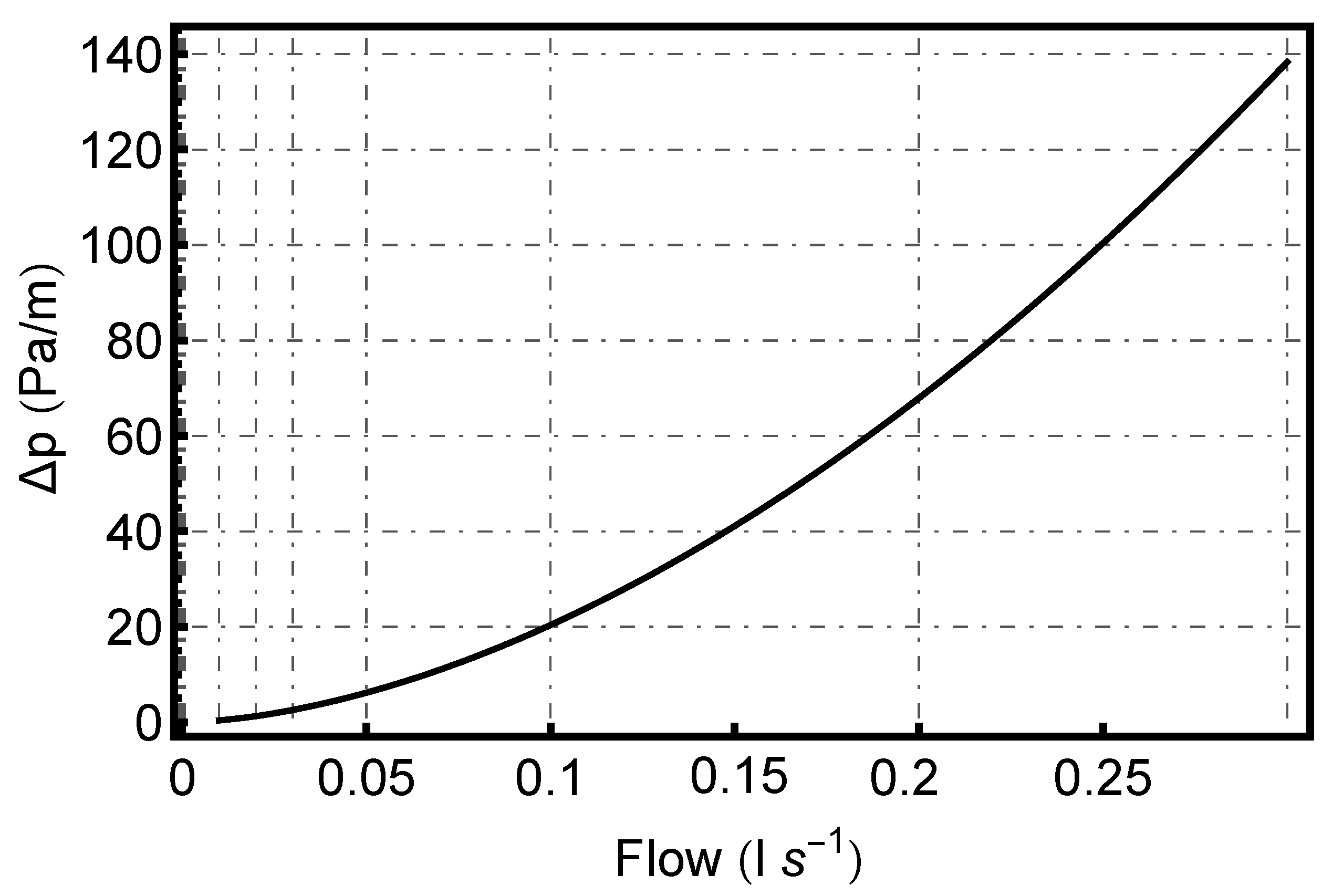
In Figure 8, the flow rates analyzed are shown reflecting the pressure drop resulting from each unit of borehole length (Pascal per meter). As expected, hydraulic losses in the borehole increase exponentially as the flow rate of fluid through it increases.
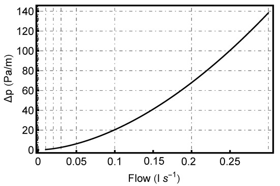
Figure 8.
Flow influence on Pressure Drop per borehole length.
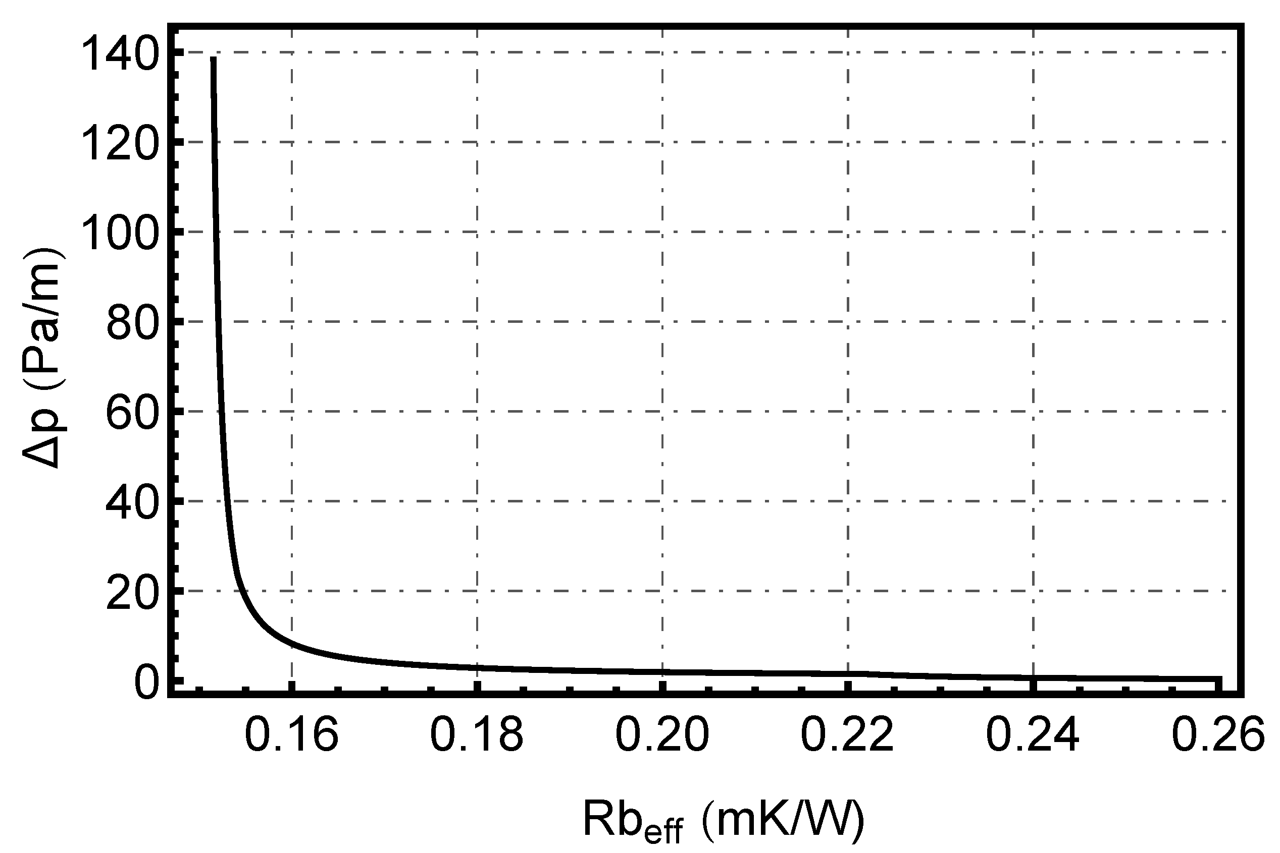
Combining Figure 7 and Figure 8 results Figure 9, which shows the significant relationship between the thermal resistance of the borehole and the pressure losses produced. It can be observed that to obtain very low values of borehole thermal resistance, a very high energy expenditure in pumping is required; and, conversely, to obtain low pressure losses, the thermal efficiency of the borehole has to be penalized. However, as it can be observed in the graph, in each configuration and properties of the borehole, there is an optimal point that minimizes those two values (the closest value to the origin). In our case, the optimal point would be approximately for a flow rate of 0.08 l/s (:0.152 mK/W, :12 Pa/m).
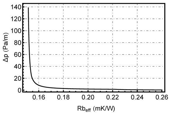
Figure 9.
Pressure drop vs. effective borehole resistance ().
4.2. Multi-Parameter Analysis
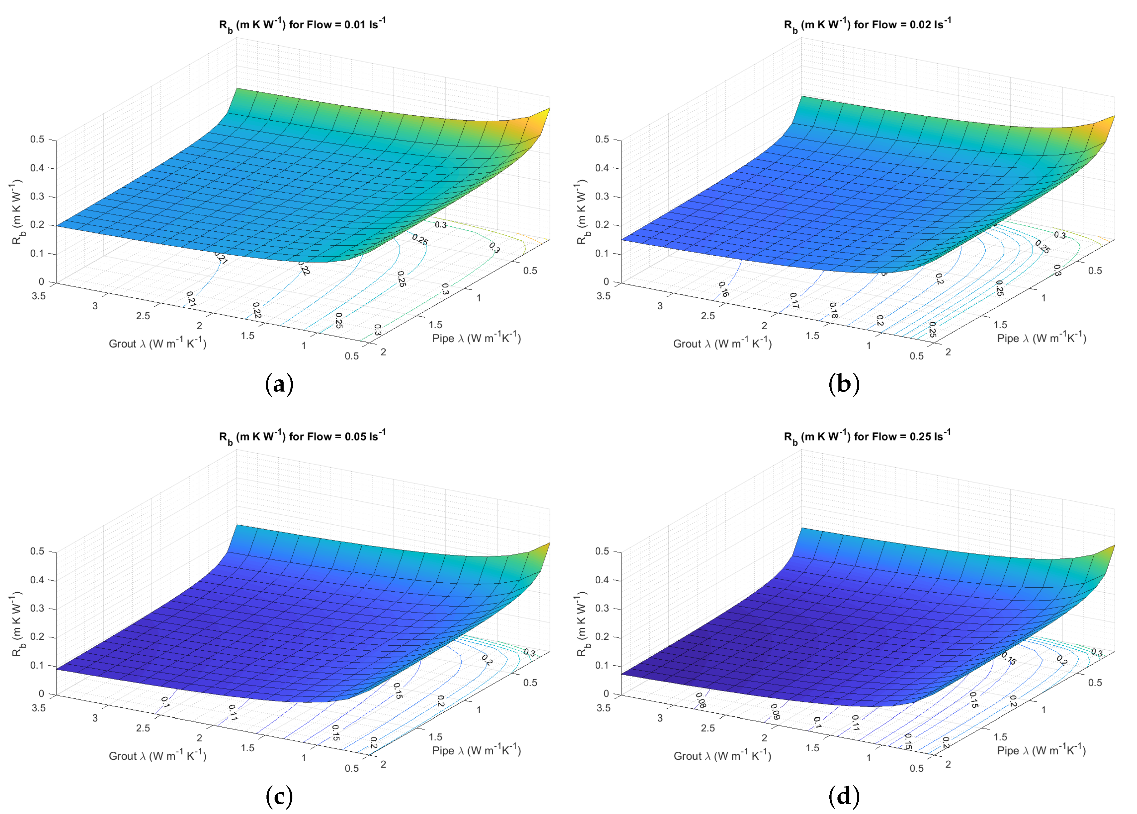
The combined influence of pipe conductivity, grouting material conductivity and fluid flow rate on the efficiency of the borehole thermal resistance has also been analyzed given the robustness of the analytical tool developed. This is performed by calculating the thermal resistance of the borehole with different input parameters of pipe conductivity, grouting material conductivity and heat carrier fluid flow rate. In Figure 10, different surfaces can be seen depending on these material conductivities for 4 reference flow rate values.
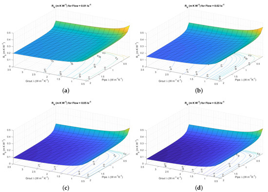
Figure 10.
Surfaces for different Flow values (in ): (a) 0.01; (b) 0.02; (c) 0.05 and (d) 0.25.
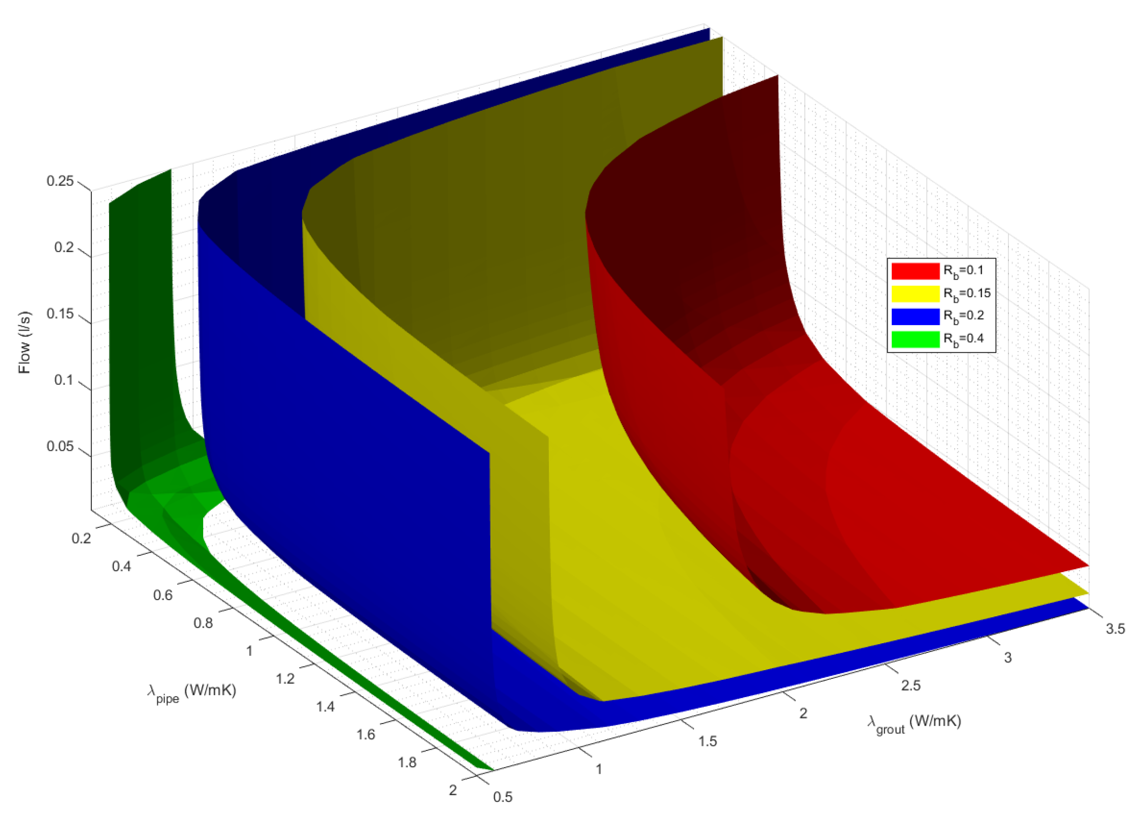
Figure 11 shows iso- surfaces: combinations of pipe conductivity, grout conductivity, and flow rate where the same borehole resistance value is obtained (the same thermal efficiency at the borehole heat exchanger).
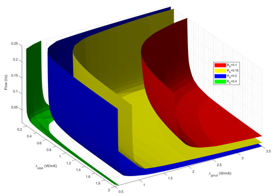
Figure 11.
Iso-surfaces for selected values: 0.1, 0.15, 0.2 and 0.4 mK/W.
The above Figures show the importance of the impact of not only optimal flow values, but also of the added effect of improved conductivity values of the pipe and grout, which can, conjointly, significantly improve the thermal efficiency of the borehole.
4.3. Scenario Analysis
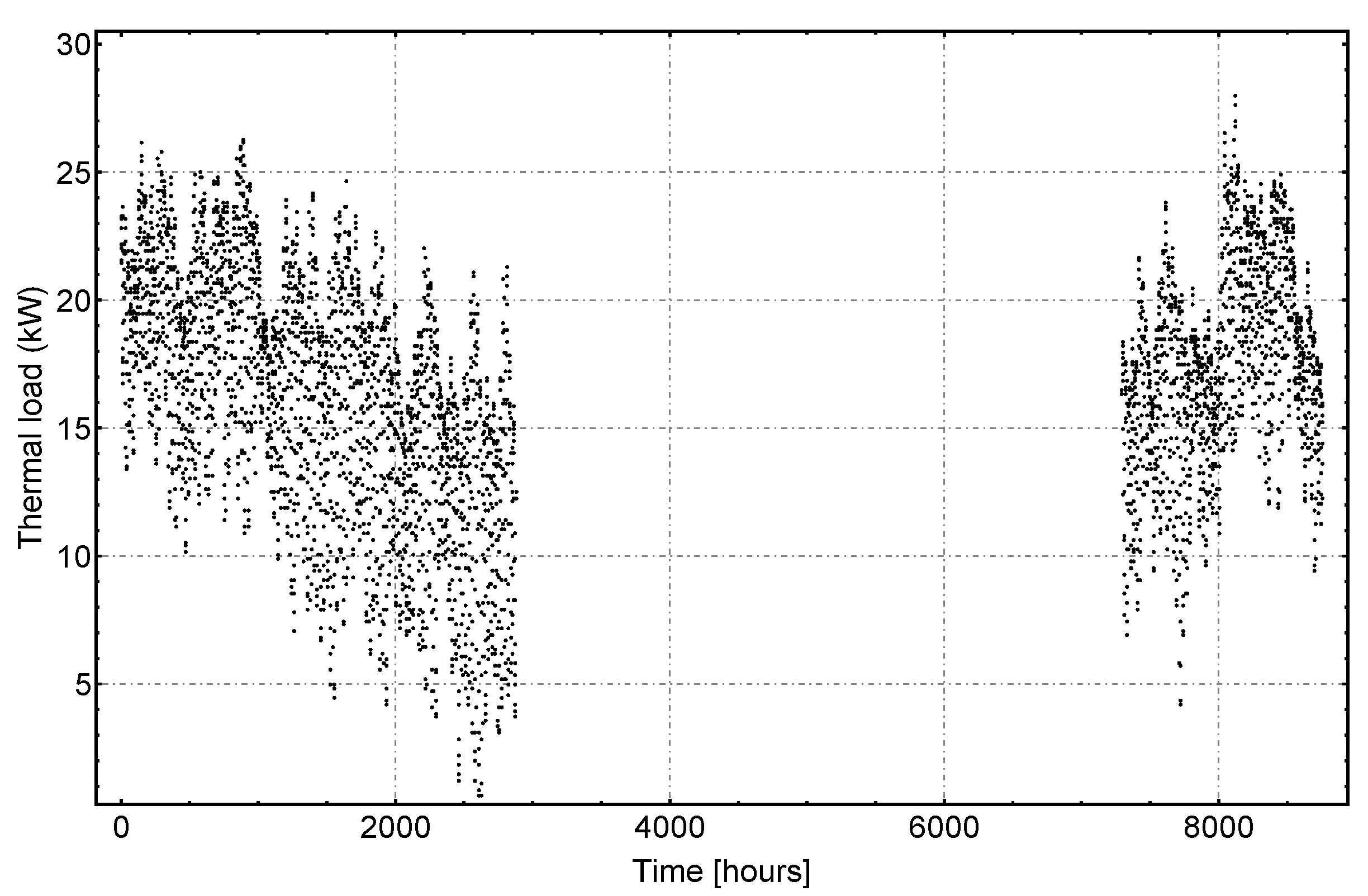
For a more detailed study of the influence on execution and operating costs, a case study is performed defining the characteristics of a geothermal installation. The installation under study is a 420 m residential building located in a continental climate ( according to Koppen climate classification) and due to the mild summer, it only requires a heating system, supplied by a geothermal heat pump with power capacity of 28 kW. The building complies with the Spanish construction standard (Technical Building Normative, 2013) [40] that implies the following thermal transmittance U-values in the envelope elements: 0.6 W/Km in the facade, 0.4 W/Km in the floor and ceiling and 2.7 W/Km in windows and external doors with a maximum of air permeability of 27 mh/m. Building hourly thermal demand is showed in Figure 12 (yearly heating thermal load of the building is 171.94 kWh/m) and the main installation characteristics are collected in Table 4. This scenario was analyzed using the DesignBuilder software, EED (Earth Energy Designer) [41], by carrying out hourly simulations of the thermal behavior of the geothermal heat exchanger field.
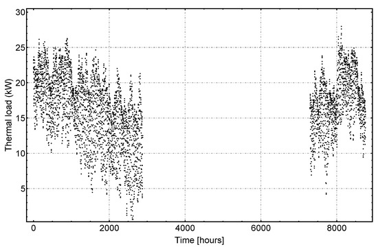
Figure 12.
Hourly thermal demand (heating) of case study.
The borehole field consists of 9 single U-tube boreholes of same characteristics of Table 1 with 90 depth and 6 m separation between them.

Table 4.
Parameters of scenario.
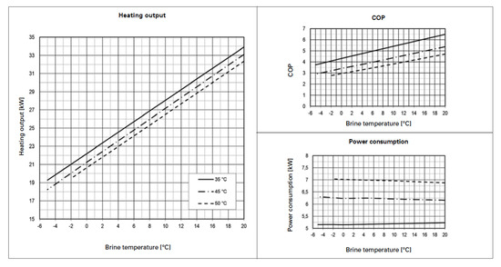
Figure 13.
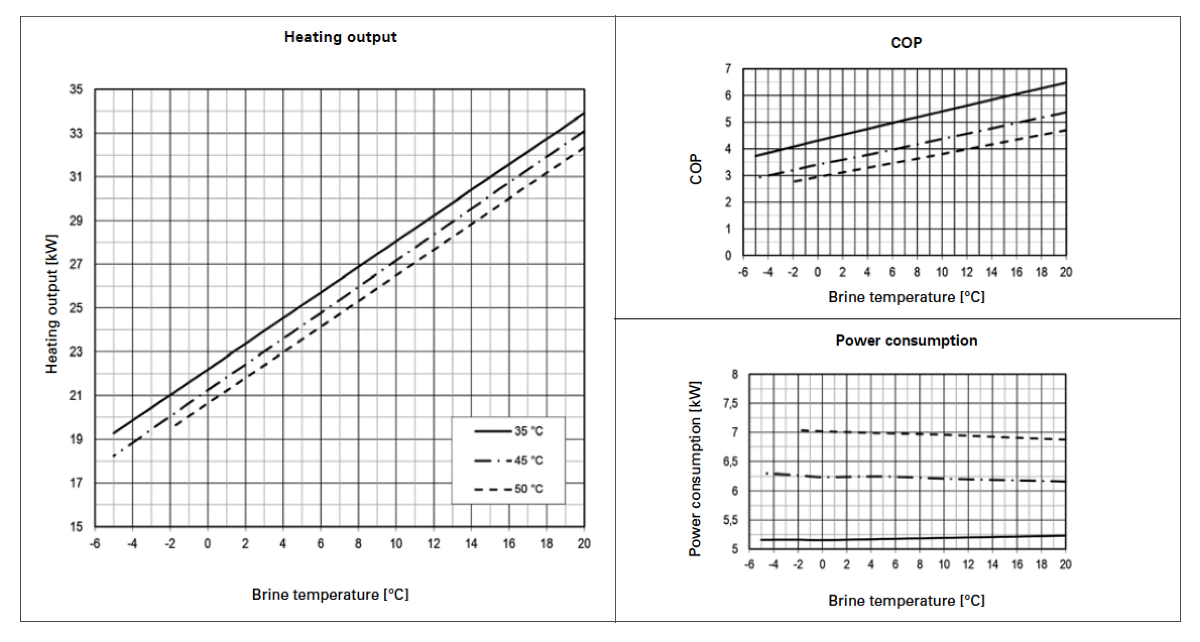
Performance curves of GMSW 28 HK Heat Pump depending on supply temperature of heating system [42].
Table 4.
Parameters of scenario.
| Borehole field | |||
|---|---|---|---|
| Borehole type | single U-tube | Borehole parameters | See Table 1 |
| Borehole field | 9 × 90 m | Borehole separation | 6 m |
| Ground properties | |||
| Undisturbed ground temperature | 18 C | Ground conductivity | 2.3 W/mK |
| Pipe properties | |||
| Installation properties | |||
| Heat Pump | GMSW 28 HK | Pipe distance from borehole to Heat Pump | 2 × 35 m |
| Common pressure losses (filter, heat pump heat exchanger, fittings,⋯) | 90 kPa | ||
4.3.1. Same Borehole Field
In the following assessment, a geothermal drilling field of the same length —9 boreholes of 90 m depth— for all flow rates is analyzed to determine the influence of the flow on the overall cost of the geothermal system (drilling and operation costs).
The results are listed in Table 5.

Table 5.
Scenarios results.
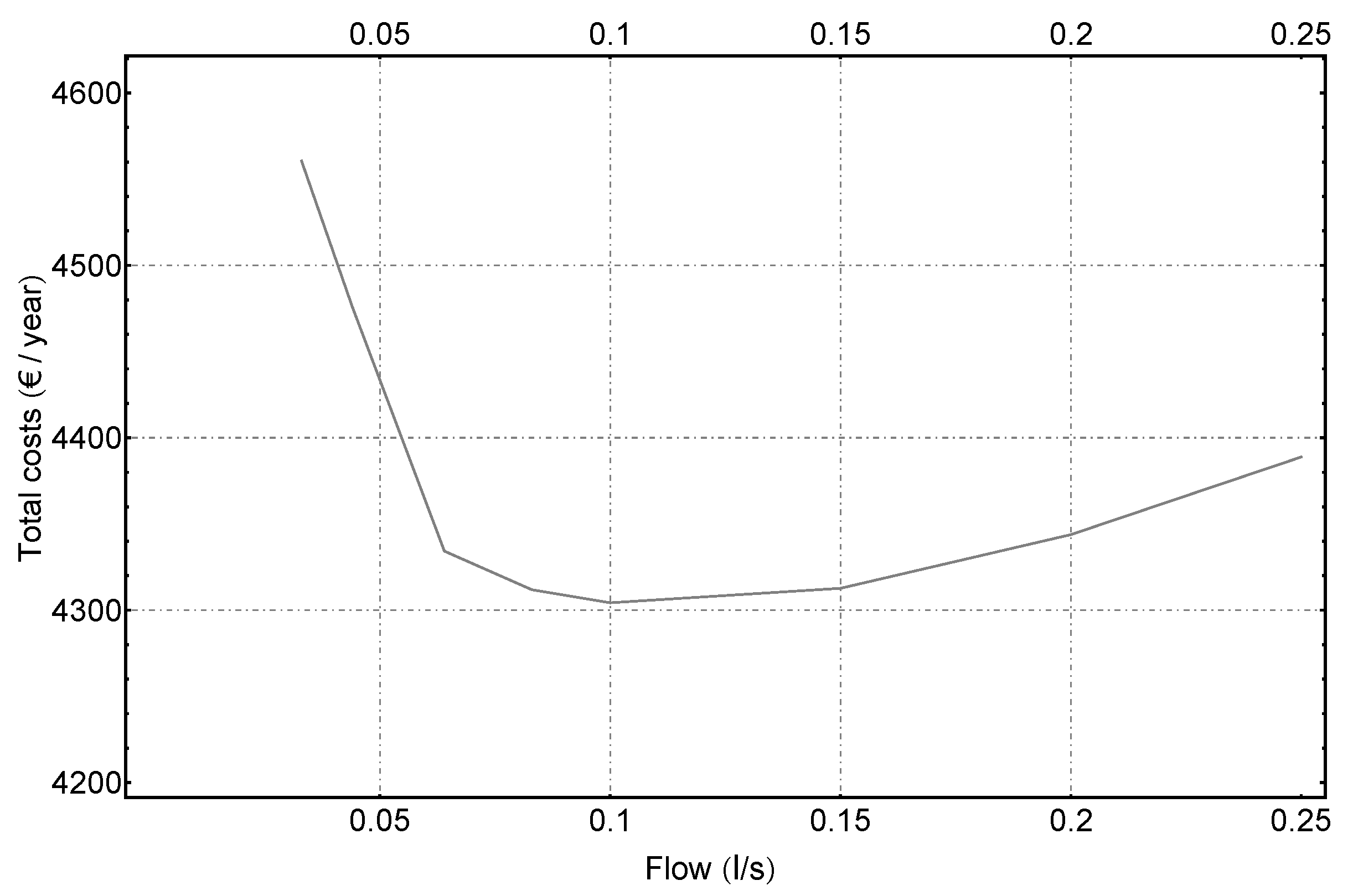
Following Figure 14 shows the total costs per year depending on the flow rate. Very low working fluid flow rate results in higher total costs, due to the increased electricity consumption of the heat-pump operation [] because of the low thermal efficiency of the borehole (higher working temperatures in the borehole field, as can be found in the Annexes). As the fluid flow rate increases, these total costs are reduced (higher thermal efficiency of the borehole), but after a certain point (in this case study, approximately 0.1 ), the pumping costs [] start to play a bigger role, increasing the total costs.
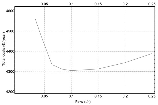
Figure 14.
Total costs per year depending on flow rate.
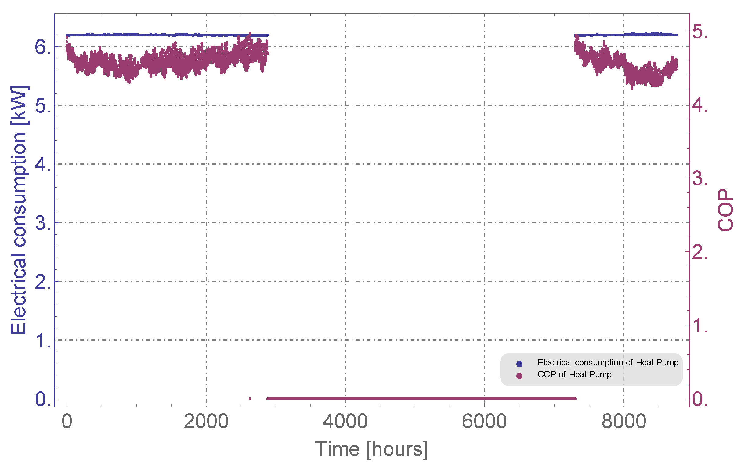
The additional data from the simulations performed for each case can be seen in the Appendix A, Appendix B, Appendix C, Appendix D, Appendix E, Appendix F, Appendix G and Appendix H. For each case it is shown:
- –
- The annual evolution of the inlet and outlet temperatures of the heat transfer fluid, which depend on the thermal performance of the borehole ().
- –
- The hourly thermal capacity of the heat pump and the rate of heat injected to the borehole throughout the year.
- –
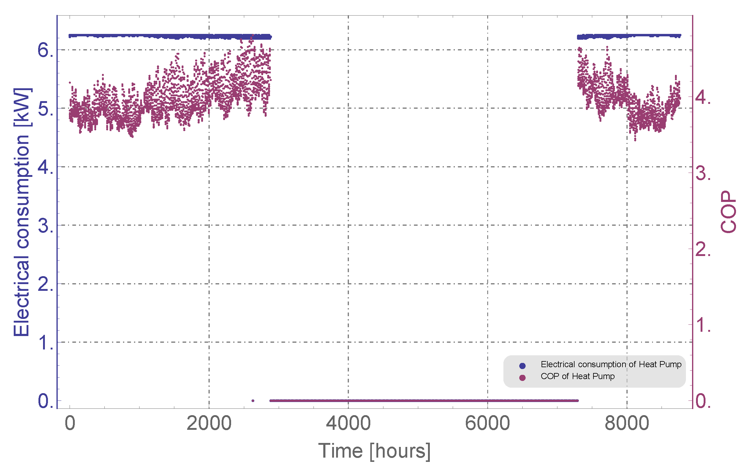
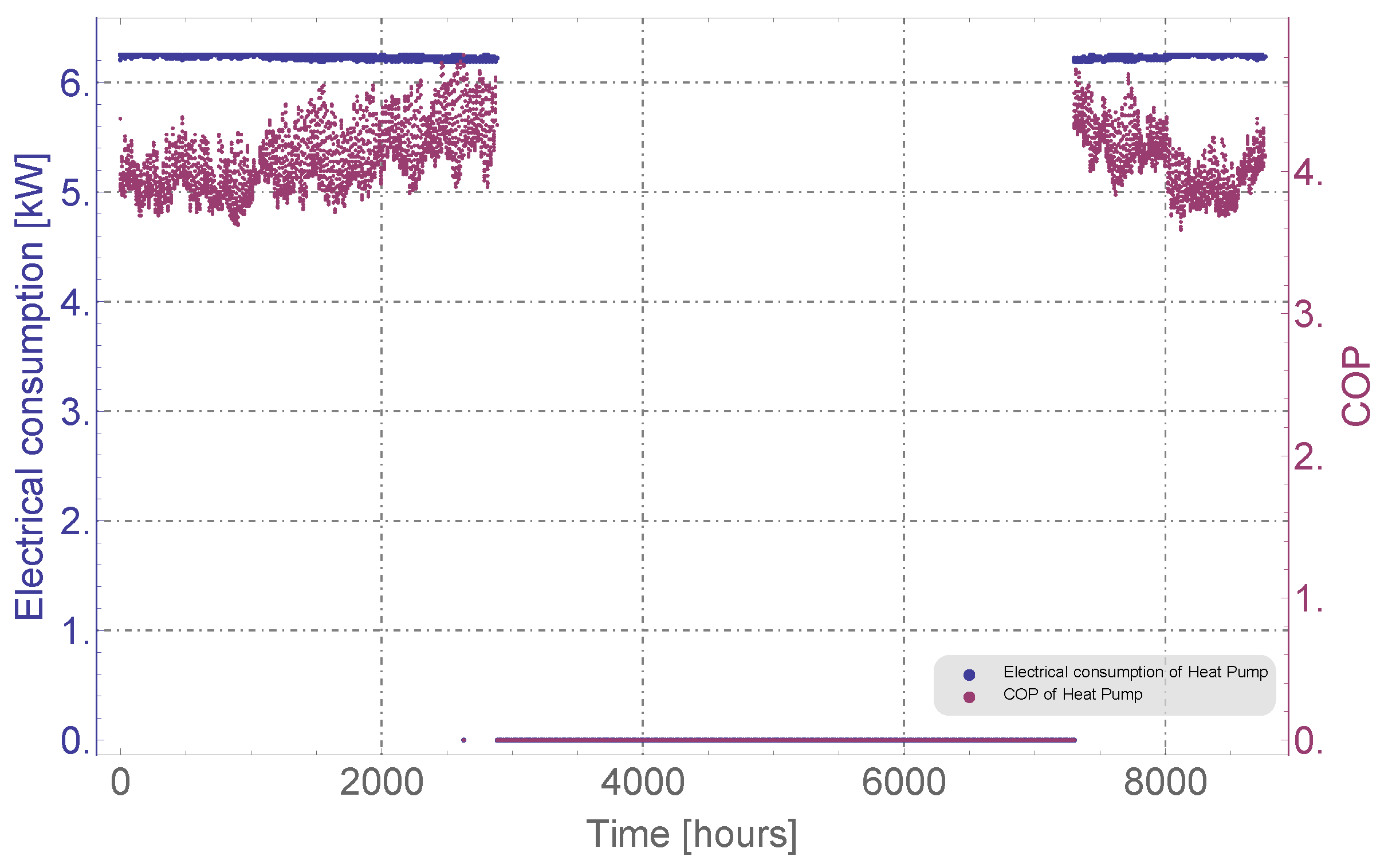
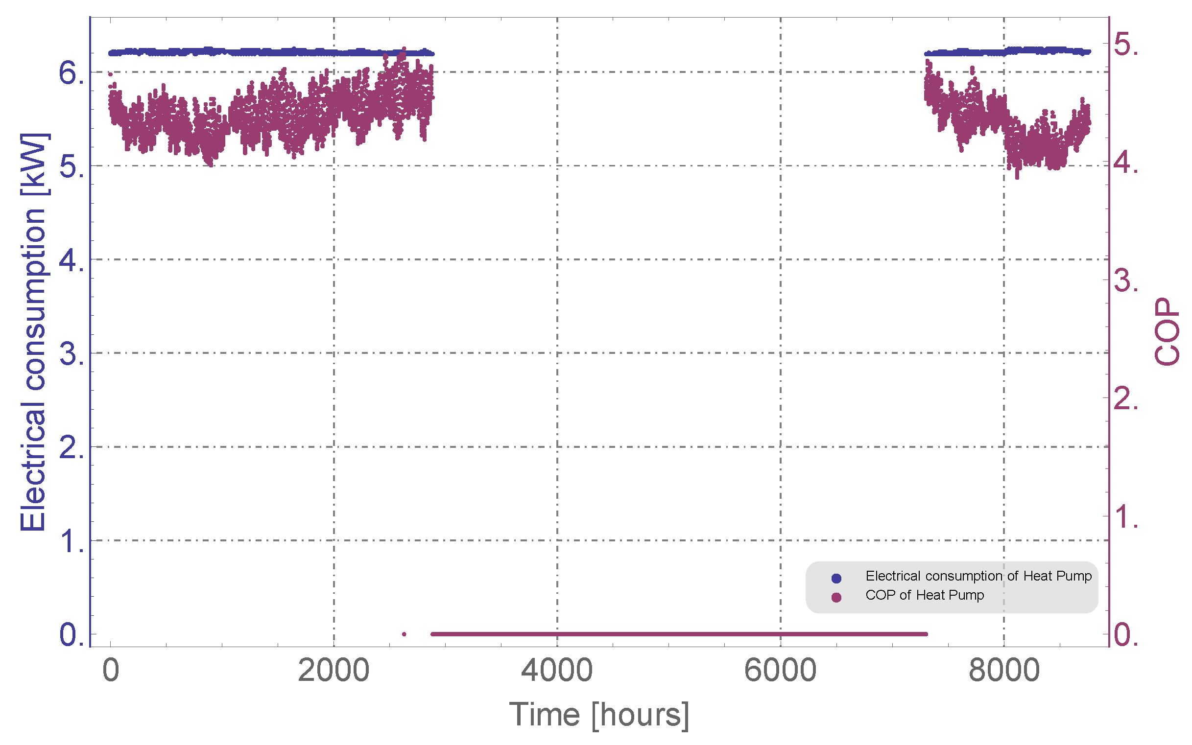
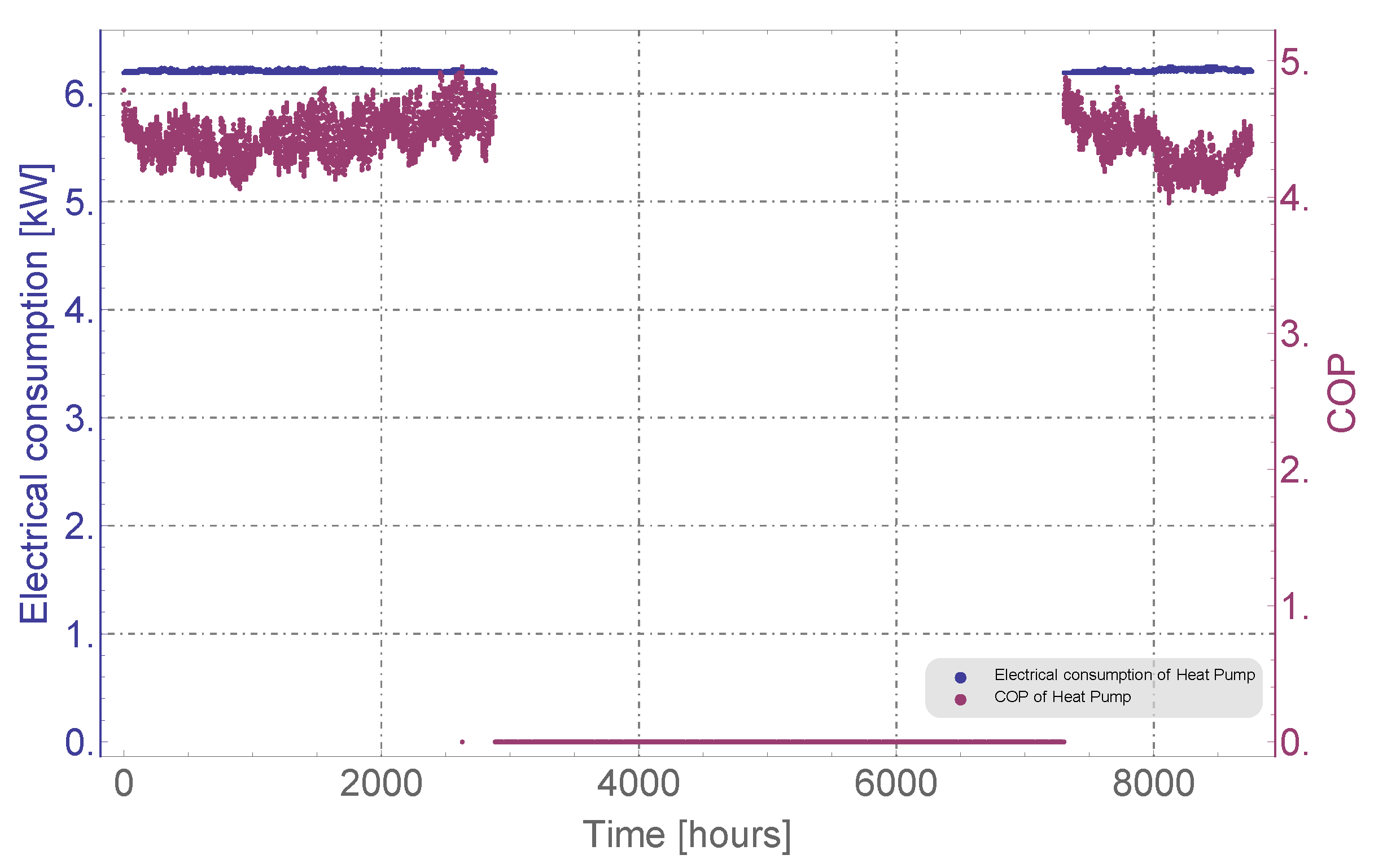
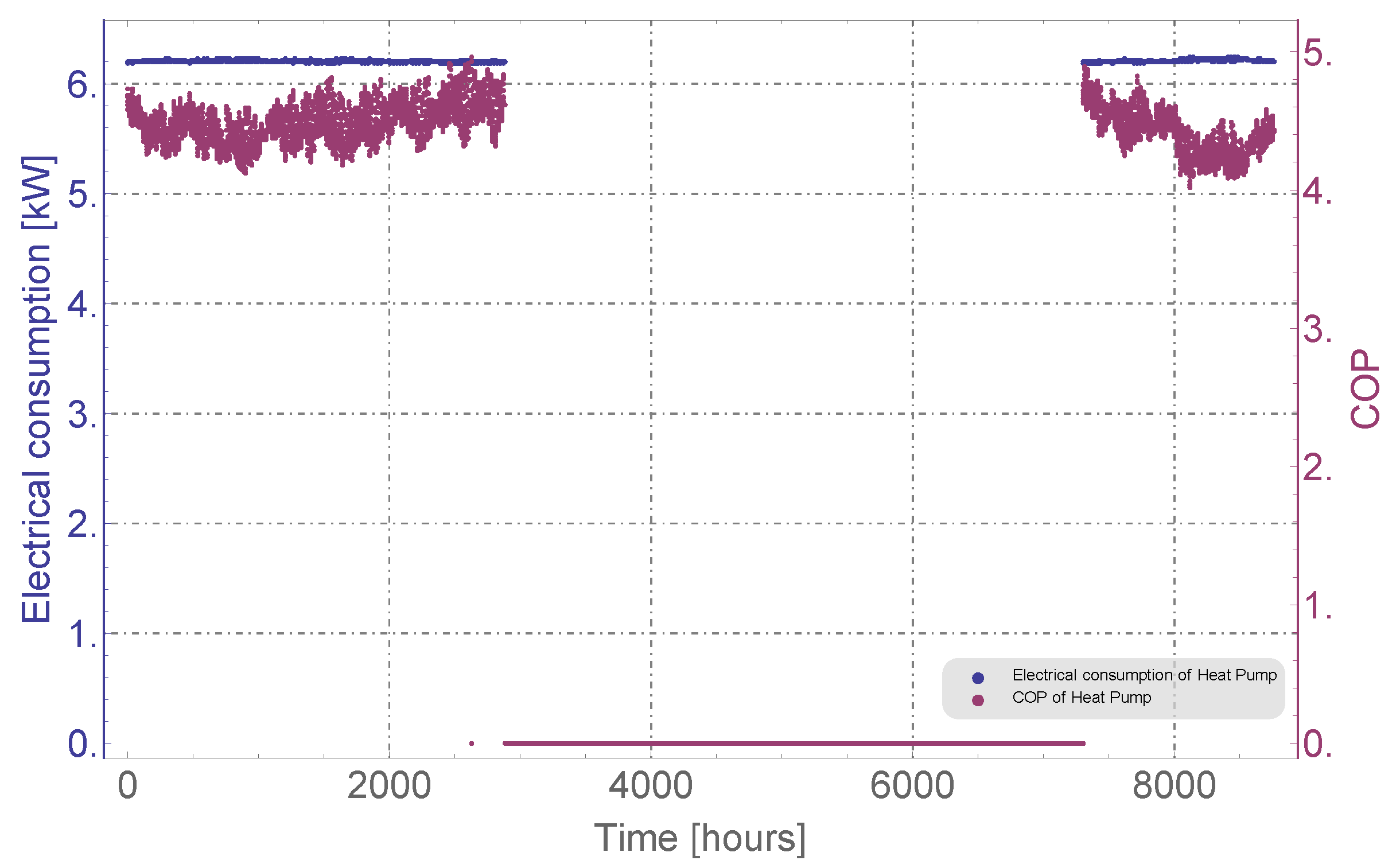
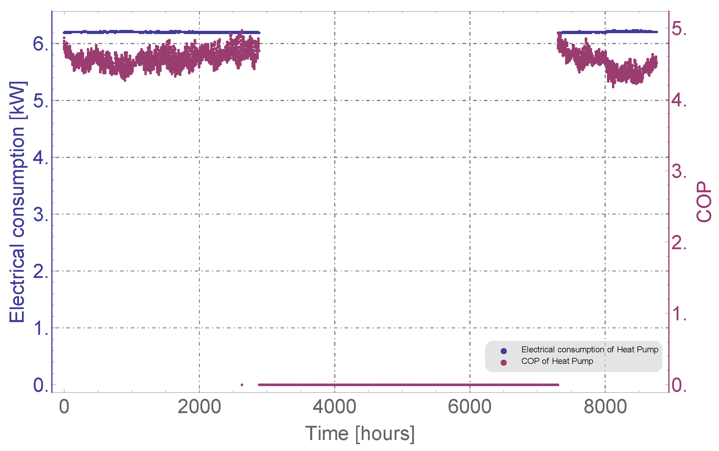
- The electric consumption of the heat pump and its efficiency (Coefficient of Performance—COP) calculated based on the heat pump rating. The value of the SPF indicated in the analysis is the COP annual average.
4.3.2. Same Heat-Pump Efficiency
By means of the Energy Earth Design (EED) software, taking as a reference the operating temperatures in the borehole field in Case #3, the total length of the geothermal field has been modified to equal those temperatures (see Figure A7), and therefore, obtain the same electrical efficiency-SPF-in the heat pump. Consequently, in cases where low flow rates penalize the thermal efficiency of the borehole, the necessary length of the geothermal field increases, and in cases of high flow rates, as there is a better thermal efficiency, a shorter length of the borehole field is required.
The simulation results are listed in Table 6.

Table 6.
Scenarios results.
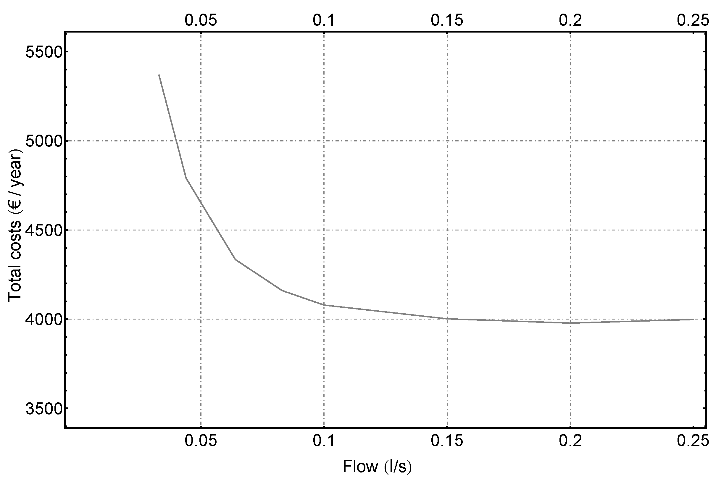
Following Figure 15 shows the total costs per year depending on the flow rate. At very low working fluid flows, very high total costs are observed, strongly penalized by the elevated drilling costs [CAPEX], due to the longer length of the borehole heat exchanger required to obtain the same thermal efficiency in the heat pump (same working temperatures in the borehole field). As the fluid flow rate increases, these total costs are reduced (lower drilling costs), but after a certain point (in this case study, approximately 0.15 l/s), the pumping costs [] start to play a bigger role, increasing the total costs. However, in the analyzed flow rates these pumping costs [] do not exceed the savings in drilling costs (although they are expected to do so at higher flows).
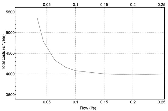
Figure 15.
Total costs per year depending on flow rate.
5. Conclusions
This work has analyzed the investment and operating costs of a typical BHE configuration taking into account the relationship between its thermal efficiency and hydraulic losses at different fluid flow rates. An extensive theoretical and numerical tool was developed to filter, refine and finally select optimal borehole configuration meeting the required criteria arising from the installation and conductivity material and evaluating the correlation between borehole thermal efficiency () and borehole pressure losses depending on the fluid flow rate. This tool has been experimentally validated with results from thermal tests (TRTs) at three different flow rates, obtaining errors between the calculated and the experimental values of less than 1.5%.
The following results can be concluded:
- –
- As expected, the borehole thermal resistance value significantly depends on the flow rate (see Figure 7). Within laminar flow (below 0.04 l/s), borehole thermal resistance is rapidly increasing with small flow rate decreases, whereas in turbulent flow, a further increase in the flow rate produces only a marginal decrease in the borehole thermal resistance.
- –
- Since pressure losses in the borehole heat exchanger are correlated with the value of the thermal resistance (see Figure 8), an optimum value is observed where the pressure losses have already decreased considerably, reducing the electrical pumping costs.
- –
- For the same flow rate value and hydraulic losses, the borehole characteristic that most penalizes borehole thermal efficiency is the low thermal conductivity of the pipe material (Figure 10), with more influence on the borehole thermal efficiency than the value of the grout thermal conductivity.
- –
- The difference obtained in borehole thermal efficiency values between the lowest pipe thermal conductivity and the highest for the same grout conductivity is about 0.2 mK/W for all values of flow rates analyzed. This relevant result, which is not a main objective of this article, opens an interesting field to analyze in future works.
To complete this theoretical analysis, hourly numerical simulations by EED program of a case scenario were carried out to check the influence of working fluid flow rate on the total costs of the installation (drilling and operating costs). As can be seen from both the analysis with the analytical tool and the scenario simulations, the flow rate affects both the efficiency of the borehole (and therefore the efficiency of the heat pump-SPF), and the pumping costs. Working at low flow rates will result in lower borehole efficiency, with a cost overrun on heat-pump consumption. On the other hand, operating at too high flows will increase the cost of pumping.
The conclusions that can be drawn are as follows:
- –
- As shown in Table 5, for the same increase in circulating flow, the improvement in the energy consumption of the heat pump is higher at low flow rates. For example, the running cost of the heat pump is reduced 4% with a flow increase from 0.033 to 0.044 l/s, but the reduction is about 0.4% in the range between 0.2 and 0.25 l/s.
- –
- When the flow rate exceeds a certain value, the penalty in the pumping operating costs are higher than the decrease in electricity consumption due the improved heat-pump performance. An optimum flow rate that optimizes the total costs of a certain BHE can be determined according to the scenario characteristics. In the case studied, this optimum is at a value of 0.1 l/s (Figure 14) representing 70% of nominal design flow rate.
- –
- If the design objective is to set the performance of the heat pump, there is a carrier flow threshold value from which a decrease in the total costs of the installation is not very significant (Figure 15).
- –
To conclude, the extensive analysis carried out in this article shows that the thermal efficiency of a BHE increases as pumping losses increase, existing, depending on borehole typology and characteristics, an optimal design point that minimizes both. What this highlights is the importance, when designing a geothermal installation, of carrying out a hydraulic assessment to evaluate the influence of the fluid flow in the borehole on both the thermal efficiency of the borehole and the electrical expenditure on the circulation pump, and therefore, a compromise must be reached between both, mainly taking into account that both have impact on the operating cost of a ground-source heat-pump system. This optimal value can be determined for each specific installation following the methodology described in this work.
It must be considered that according to the theoretical analysis, only parts of the pressure losses were included (related with the friction within the pipes). A more complete picture would need to account for additional losses caused by other system elements such as bends, valves or other singularities present in the system. On the other hand, another future work would be the evaluation with more complex models that consider the groundwater flow.
Author Contributions
Conceptualization, B.B. and J.F.U.; methodology, B.B., T.M., M.Á.M.P., J.S. and J.F.U.; software, B.B., M.Á.M.P. and J.F.U.; validation, B.B., T.M., M.Á.M.P. and J.F.U.; formal analysis, B.B., T.M., M.Á.M.P., J.S. and J.F.U.; investigation, B.B., T.M., M.Á.M.P., J.S. and J.F.U.; writing—original draft preparation, B.B. and T.M.; writing—review and editing, B.B., T.M., M.Á.M.P., J.S. and J.F.U.; visualization, M.Á.M.P.; supervision, J.S. and J.F.U.; funding acquisition, J.F.U. All authors have read and agree to the published version of the manuscript.
Funding
This research work has been supported financially by the European project GEOCOND (funded by the European Union’s Horizon 2020 research and innovation program under grant agreement No 727583) and by the European project GEO4CIVHIC (funded by the European Union’s Horizon 2020 research and innovation program under grant agreement No 792355).
Acknowledgments
This work has received funding from the European Union’s Horizon 2020 Research and Innovation program under grant agreement No [727583] and No [792355]. 

Conflicts of Interest
The authors declare that they have no known competing financial interests or personal relationships that could have appeared to influence the work reported in this paper. The information and views set out in this article are those of the authors and do not necessarily reflect the official opinion of the European Union. Neither the European Union institutions and bodies nor any person acting on their behalf may be held responsible for the use which may be made of the information contained therein.
Abbreviations
The following abbreviations are used in this manuscript:
| Ground thermal conductivity (W/mK) | |
| Fluid thermal conductivity (W/mK) | |
| Annual energy Operating Cost of Heat Pump (€/year) | |
| Annual energy Operating Cost of Circulating Pump (€/year) | |
| BHE | Borehole Heat Exchanger |
| CAPEX | Capital Expenses |
| COP | Coefficient of Performance |
| GSHP | Ground-Source Heat Pump |
| GHE | Ground Heat Exchanger |
| H | Borehole deep (m) |
| Nusselt number | |
| OPEX | Operating Expenses |
| Pressure drop (Pa) | |
| Pressure drop per unit length of BHE (Pa/m) | |
| Prandtl number | |
| PID | Proportional Integral Derivative (PID) Control |
| q | Thermal power heat ratio (W/m) |
| Borehole thermal resistance (mK/W) | |
| Reynolds number | |
| Outer radius of the pipe (m) | |
| Inner radius of the pipe (m) | |
| Total borehole resistance (mK/W)) | |
| SPF | Seasonal Performance Factor |
| Undisturbed ground temperature [C] | |
| Fluid temperature (C) | |
| Surrounding ground temperature (C) | |
| TRT | Thermal Response Test |
Appendix A. Case 1: Flow 0.033 L/S
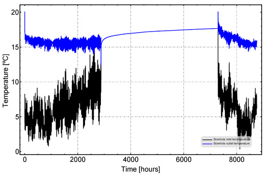
Figure A1.
Inlet and Outlet temperature at borehole.
Figure A1.
Inlet and Outlet temperature at borehole.
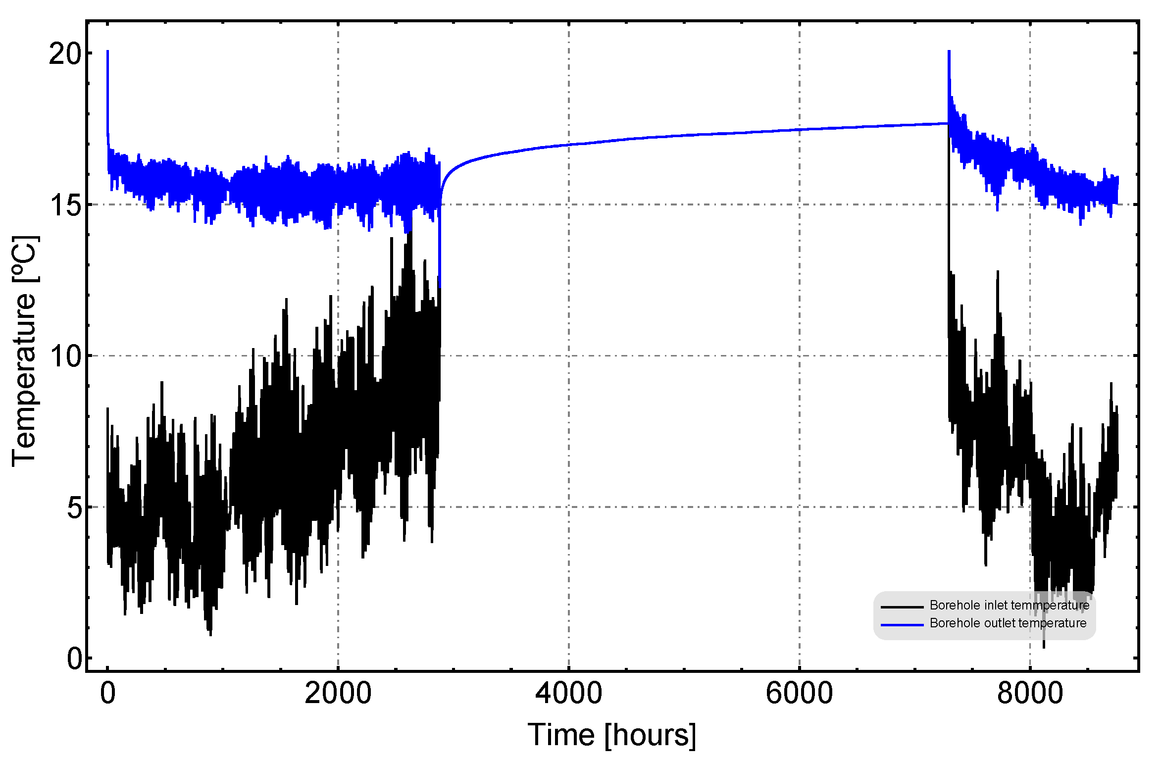
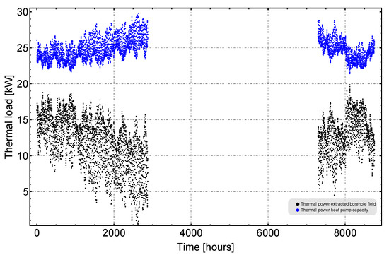
Figure A2.
Thermal power extracted from the borehole field and Thermal power capacity of the heat pump.
Figure A2.
Thermal power extracted from the borehole field and Thermal power capacity of the heat pump.
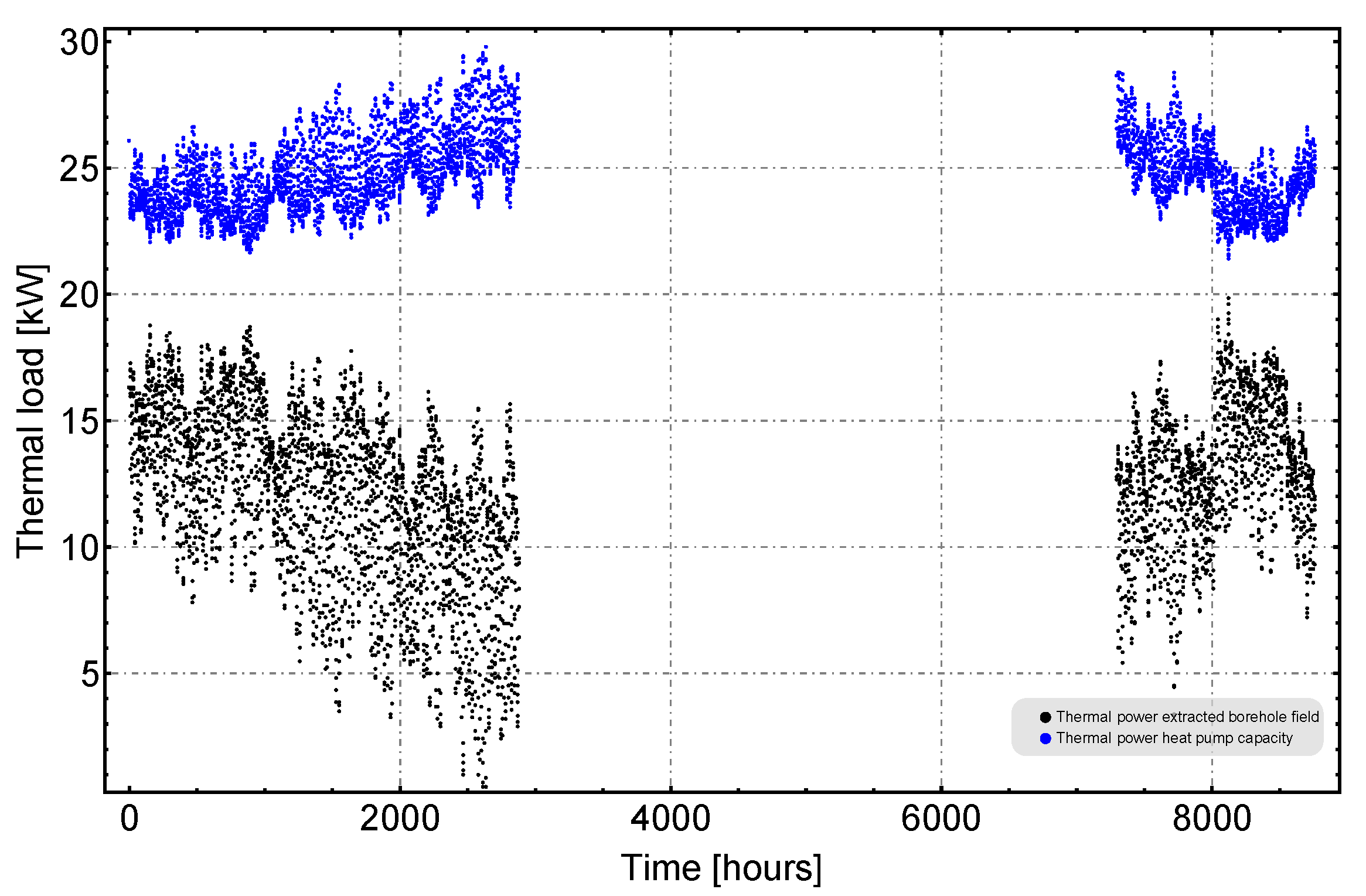
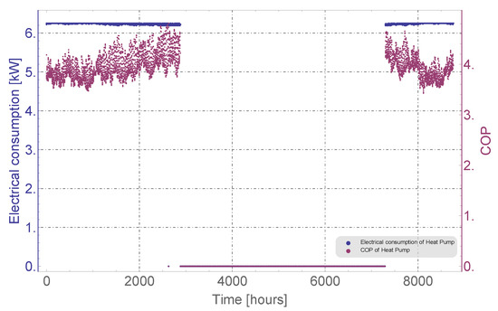
Figure A3.
COP and Electrical consumption of the heat pump.
Figure A3.
COP and Electrical consumption of the heat pump.
Appendix B. Case 2: Flow 0.044 L/S
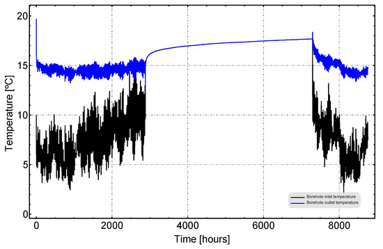
Figure A4.
Inlet and Outlet temperature at borehole.
Figure A4.
Inlet and Outlet temperature at borehole.
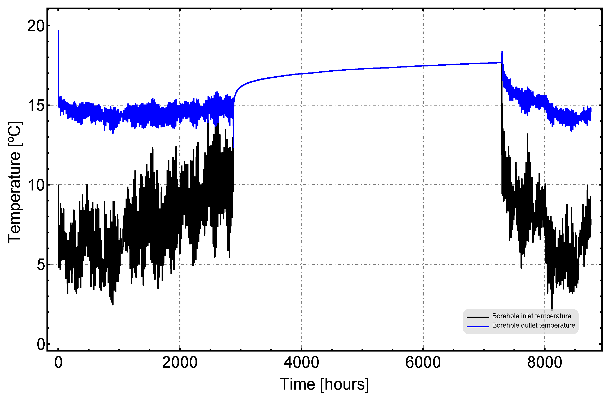
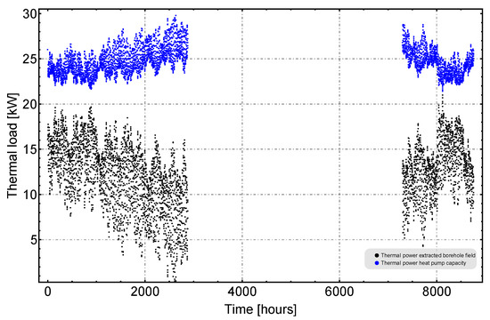
Figure A5.
Thermal power extracted from the borehole field and Thermal power capacity of the heat pump.
Figure A5.
Thermal power extracted from the borehole field and Thermal power capacity of the heat pump.
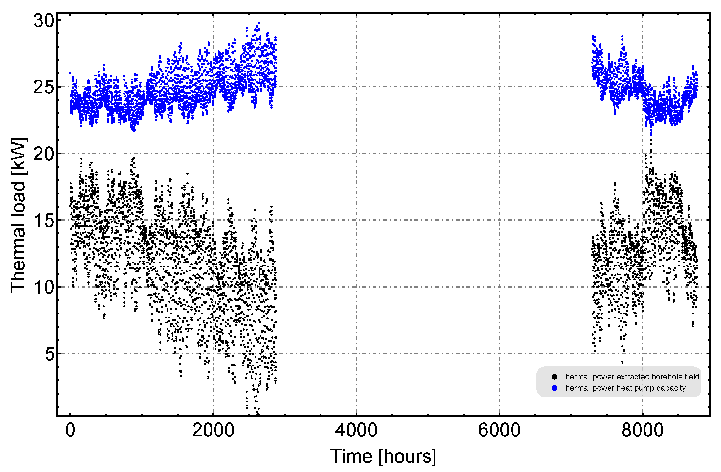
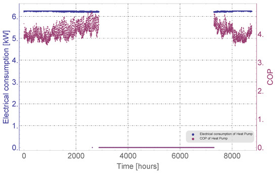
Figure A6.
COP and Electrical consumption of the heat pump.
Figure A6.
COP and Electrical consumption of the heat pump.
Appendix C. Case 3: Flow 0.064 L/S
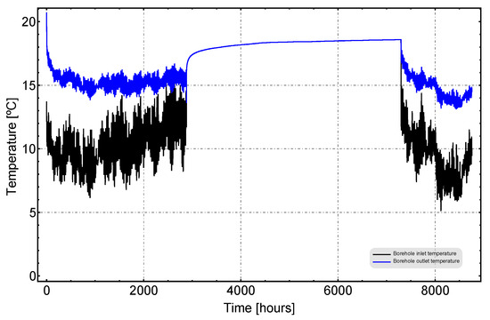
Figure A7.
Inlet and Outlet temperature at borehole.
Figure A7.
Inlet and Outlet temperature at borehole.
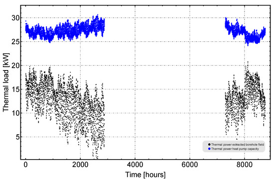
Figure A8.
Thermal power extracted from the borehole field and Thermal power capacity of the heat pump.
Figure A8.
Thermal power extracted from the borehole field and Thermal power capacity of the heat pump.
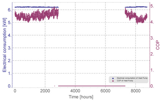
Figure A9.
COP and Electrical consumption of the heat pump.
Figure A9.
COP and Electrical consumption of the heat pump.
Appendix D. Case 4: Flow 0.083 L/S
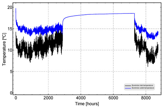
Figure A10.
Inlet and Outlet temperature at borehole.
Figure A10.
Inlet and Outlet temperature at borehole.
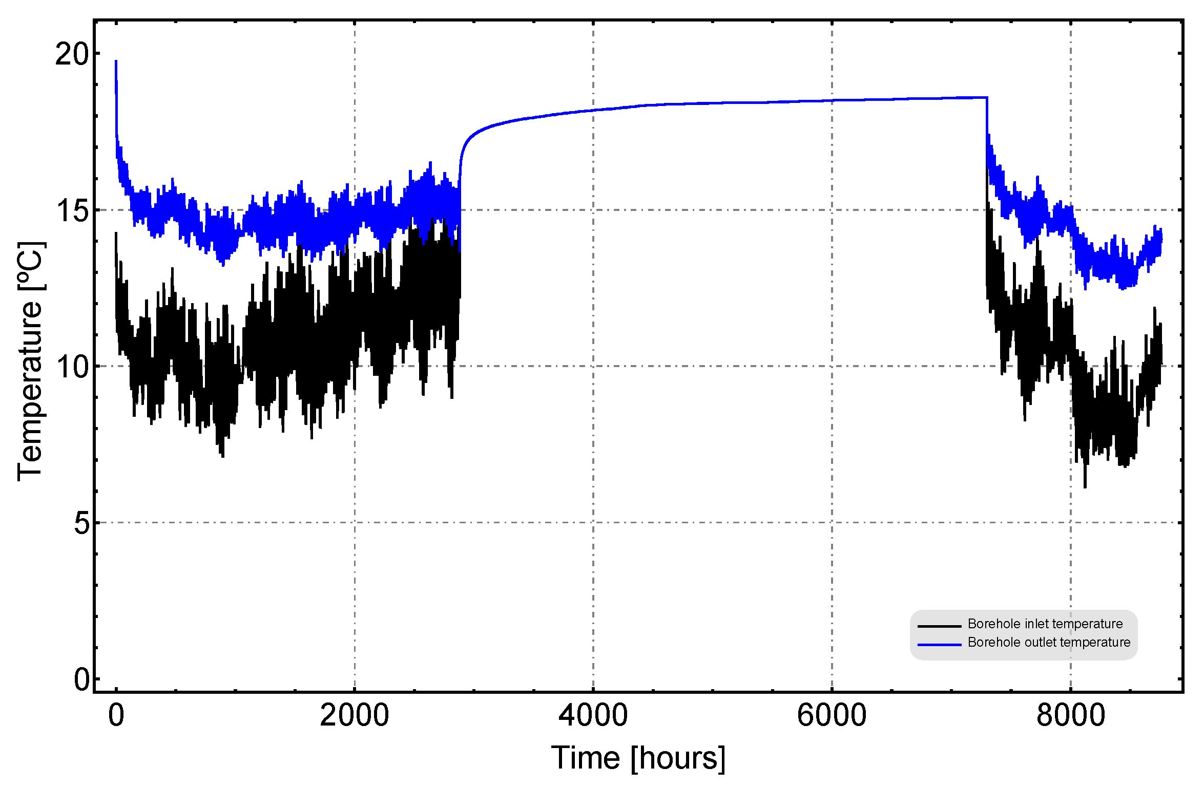
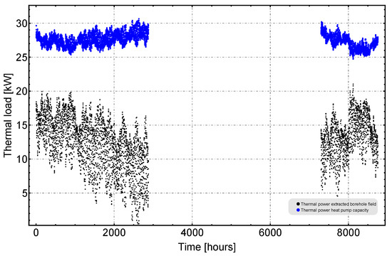
Figure A11.
Thermal power extracted from the borehole field and Thermal power capacity of the heat pump.
Figure A11.
Thermal power extracted from the borehole field and Thermal power capacity of the heat pump.
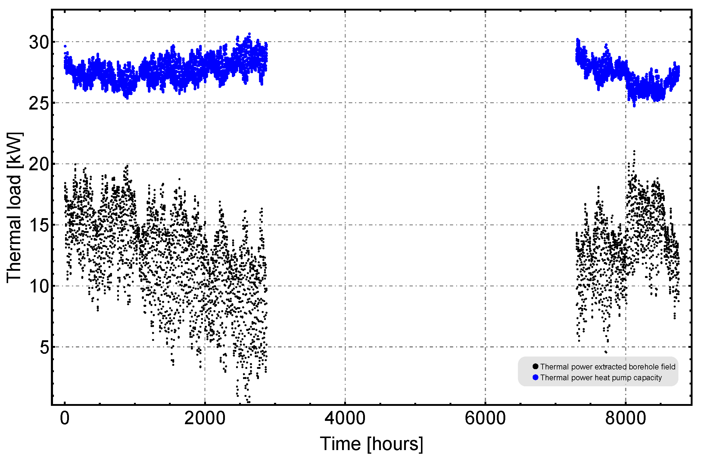
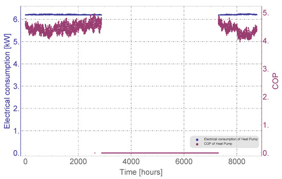
Figure A12.
COP and Electrical consumption of the heat pump.
Figure A12.
COP and Electrical consumption of the heat pump.
Appendix E. Case 5: Flow 0.1 L/S
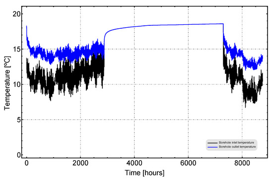
Figure A13.
Inlet and Outlet temperature at borehole.
Figure A13.
Inlet and Outlet temperature at borehole.
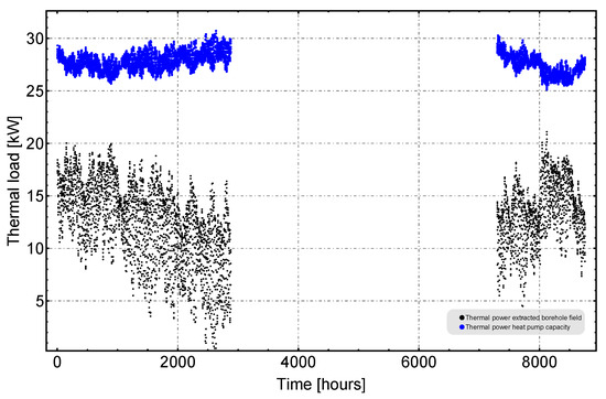
Figure A14.
Thermal power extracted from the borehole field and Thermal power capacity of the heat pump.
Figure A14.
Thermal power extracted from the borehole field and Thermal power capacity of the heat pump.
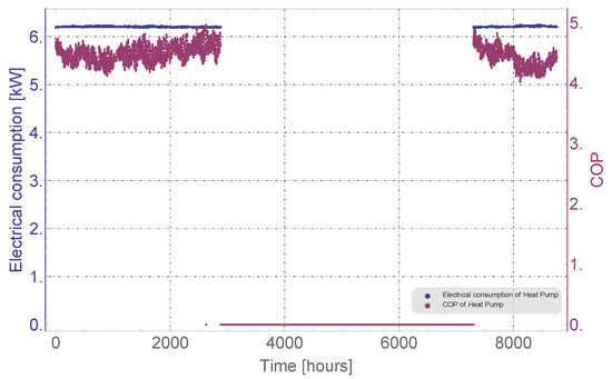
Figure A15.
COP and Electrical consumption of the heat pump.
Figure A15.
COP and Electrical consumption of the heat pump.
Appendix F. Case 6: Flow 0.15 L/S
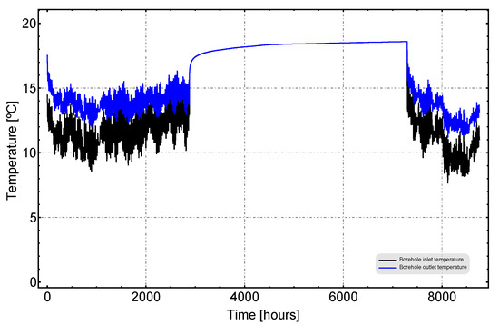
Figure A16.
Inlet and Outlet temperature at borehole.
Figure A16.
Inlet and Outlet temperature at borehole.
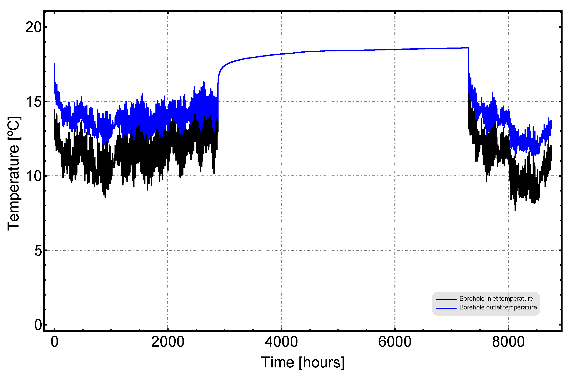
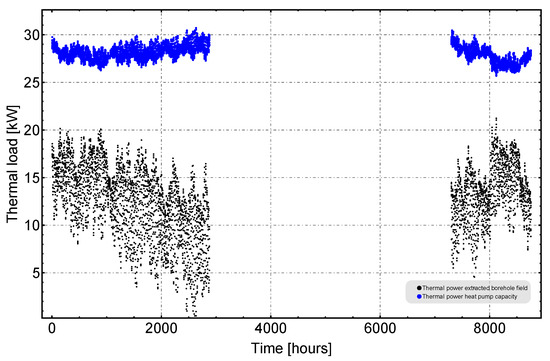
Figure A17.
Thermal power extracted from the borehole field and Thermal power capacity of the heat pump.
Figure A17.
Thermal power extracted from the borehole field and Thermal power capacity of the heat pump.
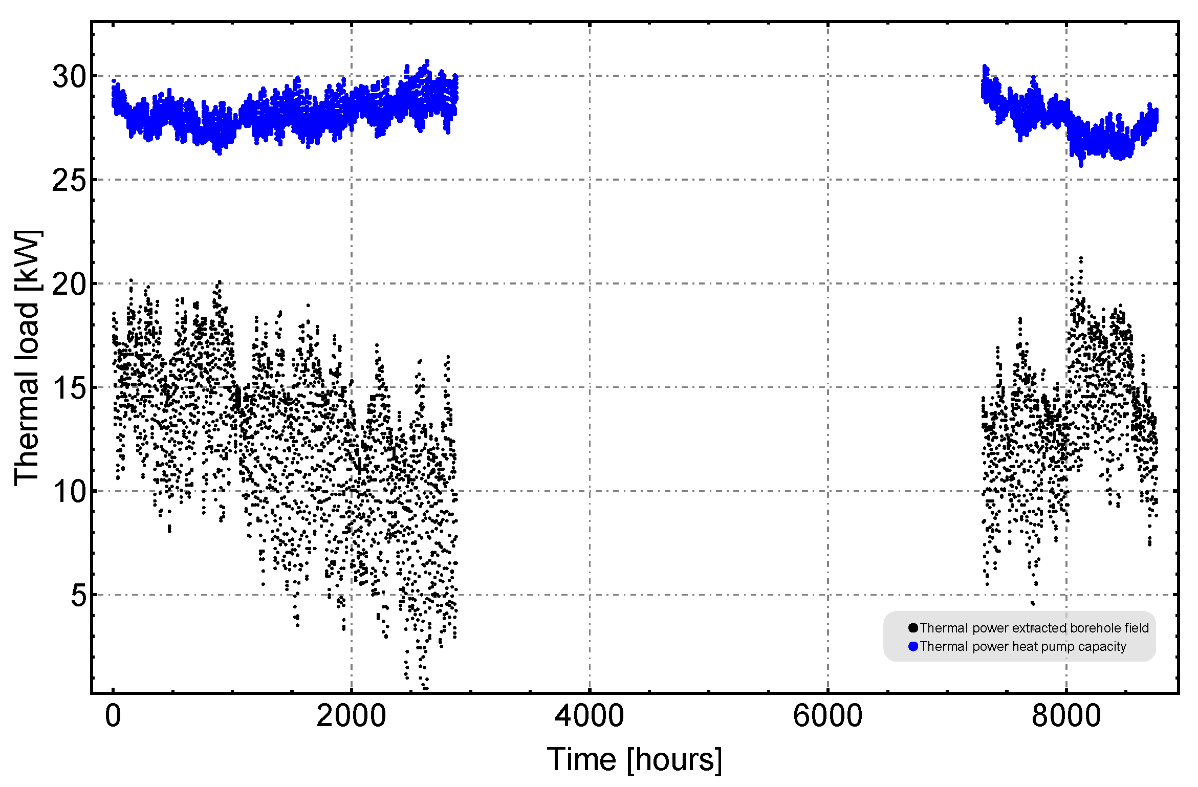
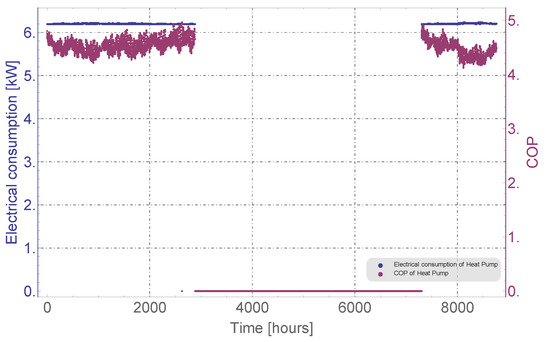
Figure A18.
COP and Electrical consumption of the heat pump.
Figure A18.
COP and Electrical consumption of the heat pump.
Appendix G. Case 7: Flow 0.2 L/S
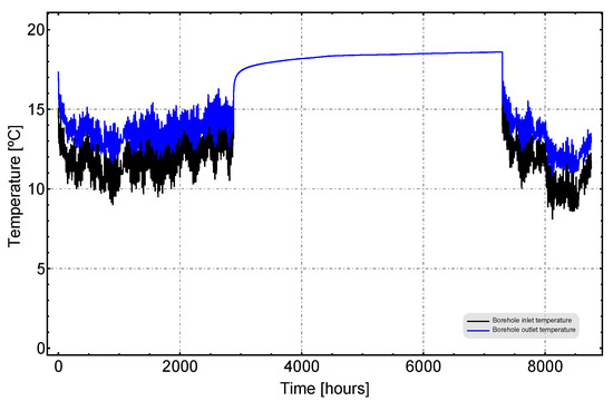
Figure A19.
Inlet and Outlet temperature at borehole.
Figure A19.
Inlet and Outlet temperature at borehole.
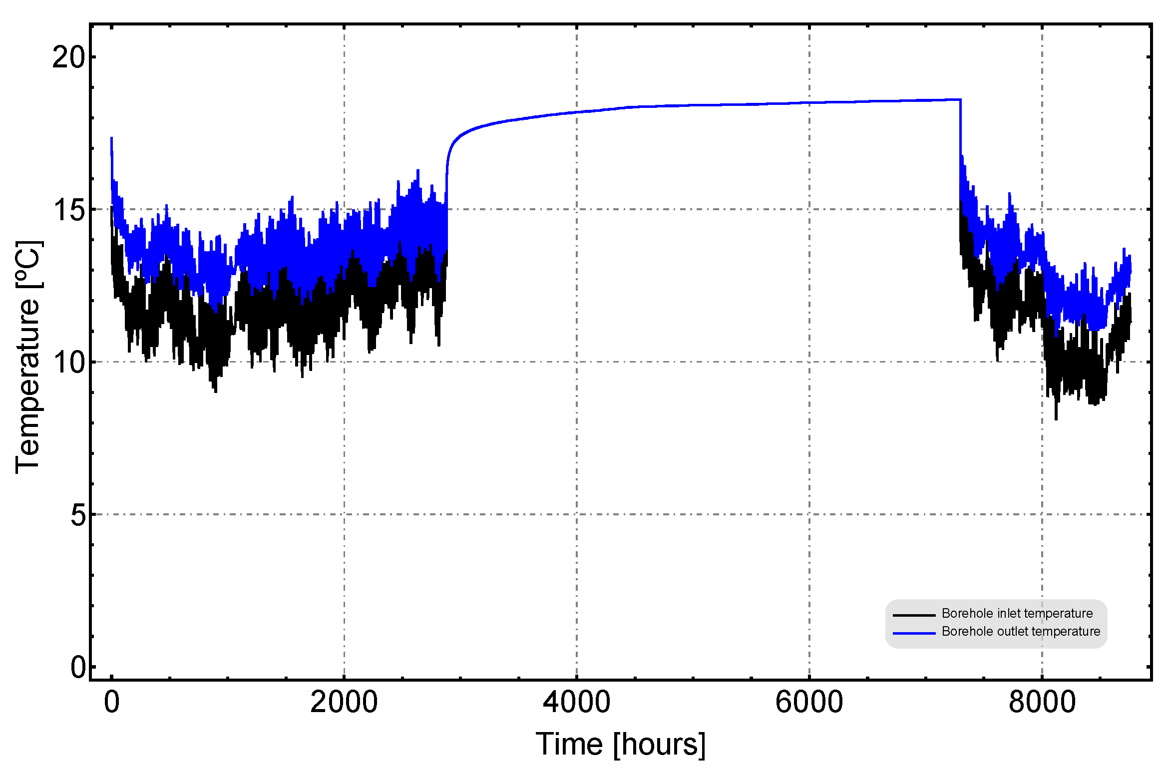
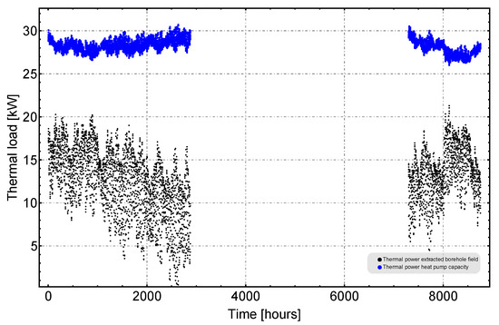
Figure A20.
Thermal power extracted from the borehole field and Thermal power capacity of the heat pump.
Figure A20.
Thermal power extracted from the borehole field and Thermal power capacity of the heat pump.
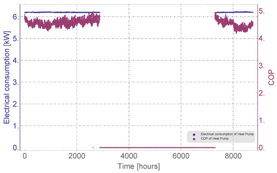
Figure A21.
COP and Electrical consumption of the heat pump.
Figure A21.
COP and Electrical consumption of the heat pump.
Appendix H. Case 8: Flow 0.25 L/S
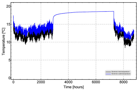
Figure A22.
Inlet and Outlet temperature at borehole.
Figure A22.
Inlet and Outlet temperature at borehole.
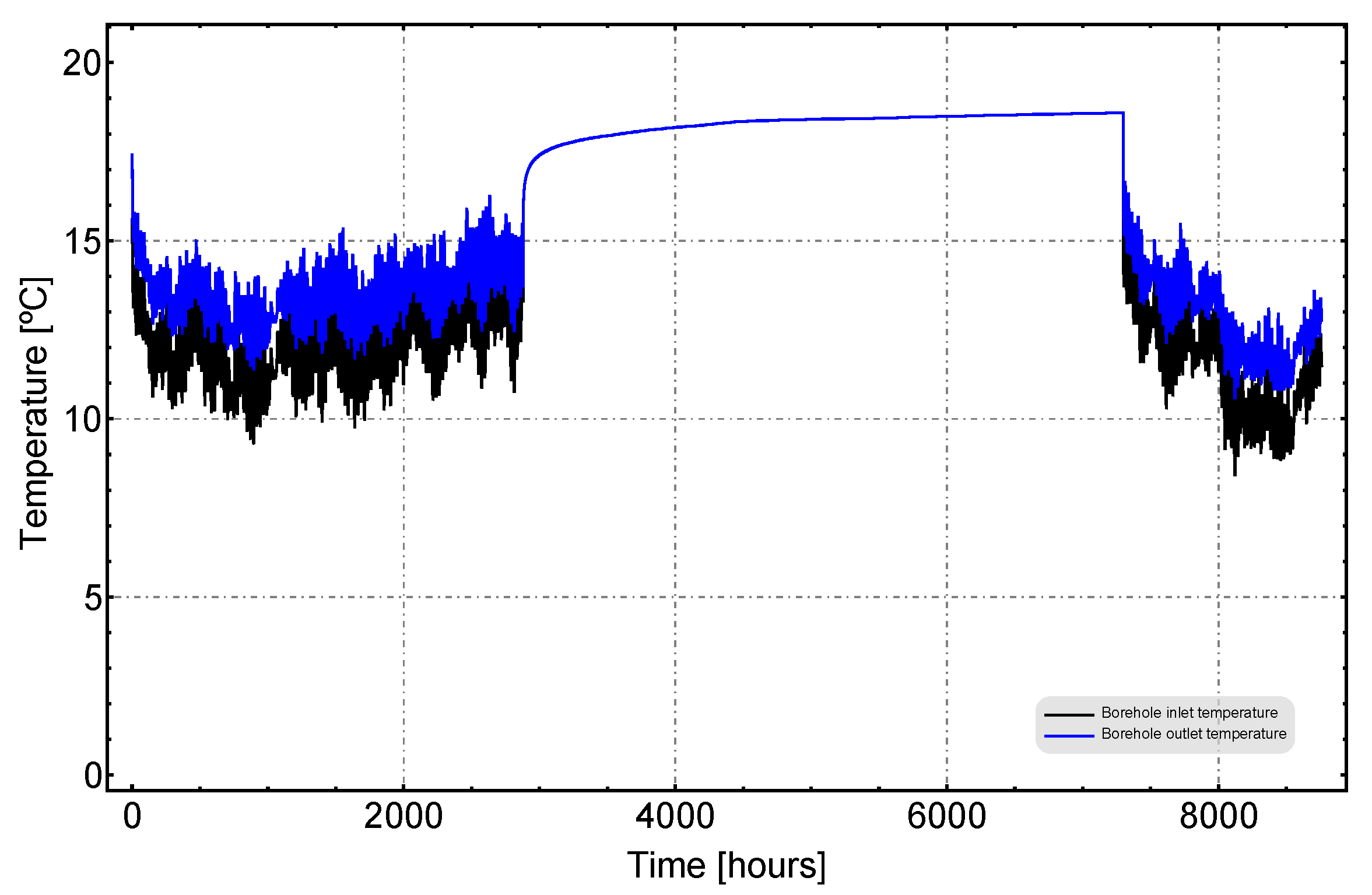
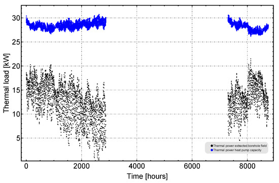
Figure A23.
Thermal power extracted from the borehole field and Thermal power capacity of the heat pump.
Figure A23.
Thermal power extracted from the borehole field and Thermal power capacity of the heat pump.
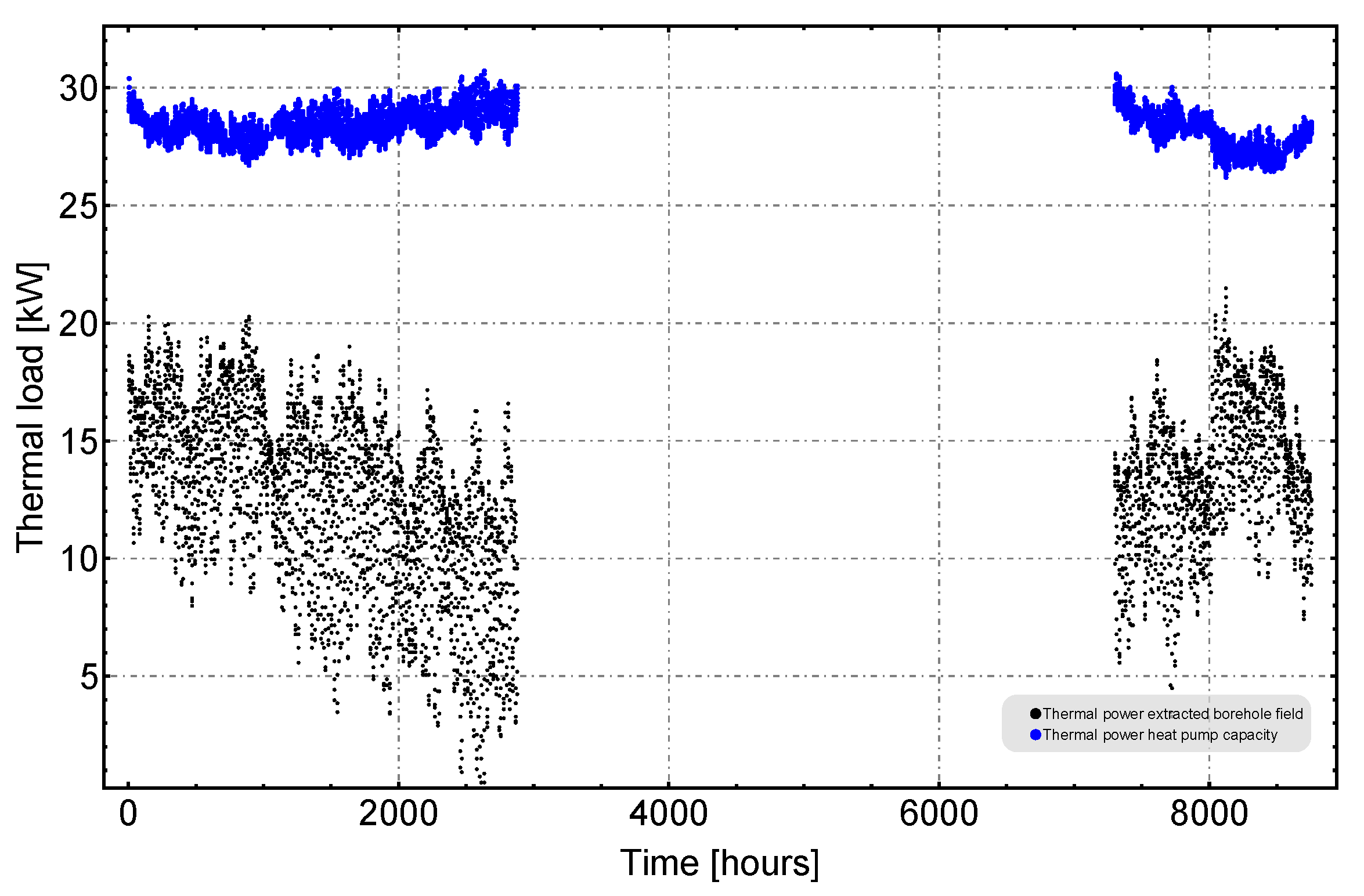
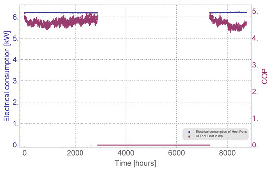
Figure A24.
COP and Electrical consumption of the heat pump.
Figure A24.
COP and Electrical consumption of the heat pump.
References
- Mogensen, P. Fluid to Duct Wall Heat Transfer in Duct System Heat Storages. In Proceedings of the International Conference on Subsurface Heat Storage in Theory and Practice, Stockholm, Sweden, 6–8 June 1983. [Google Scholar]
- Eskilson, P. Thermal Analysis of Heat Extraction Boreholes. Ph.D. Thesis, Lund University, Lund, Sweden, 1987. [Google Scholar]
- Hellström, G. Ground Heat Storage: Thermal Analyses of Duct Storage Systems. Ph.D. Thesis, Lund University, Lund, Sweden, 1991. [Google Scholar]
- ASHRAE. AHSRAE Handbook HVAC Application. In Geothermal Energy; American Society of Heating, Refrigerating and Air Conditioning Engineers: Atlanta, GA, USA, 2007; Chapter 32. [Google Scholar]
- Sáez Blázquez, C.; Piedelobo, L.; Fernández-Hernández, J.; Nieto, I.M.; Martín, A.F.; Lagüela, S.; González-Aguilera, D. Novel Experimental Device to Monitor the Ground Thermal Exchange in a Borehole Heat Exchanger. Energies 2020, 13, 1270. [Google Scholar] [CrossRef]
- Bae, S.M.; Nam, Y.; Shim, B.O. Feasibility Study of Ground Source Heat Pump System Considering Underground Thermal Properties. Energies 2018, 11, 1786. [Google Scholar] [CrossRef]
- Bilić, T.; Raos, S.; Ilak, P.; Rajšl, I.; Pašičko, R. Assessment of Geothermal Fields in the South Pannonian Basin System Using a Multi-Criteria Decision-Making Tool. Energies 2020, 13, 1026. [Google Scholar] [CrossRef]
- Gu, Y.; O’Neal, D. Development of an equivalent diameter expression for vertical U-Tubes used in ground-coupled heat pumps. ASHRAE Trans. 1998, 104, 347–355. [Google Scholar]
- Philippe, M.; Bernier, M.; Marchio, D. Sizing Calculation Spreadsheet Vertical Geothermal Borefields. ASHRAE J. 2010, 52, 7. [Google Scholar]
- Lamarche, L.; Raymond, J.; Koubikana Pambou, C.H. Evaluation of the Internal and Borehole Resistances during Thermal Response Tests and Impact on Ground Heat Exchanger Design. Energies 2018, 11, 38. [Google Scholar] [CrossRef]
- Vella, C.; Borg, S.P.; Micallef, D. The Effect of Shank-Space on the Thermal Performance of Shallow Vertical U-Tube Ground Heat Exchangers. Energies 2020, 13, 602. [Google Scholar] [CrossRef]
- Beier, R.; Ewbank, G. In-Situ Thermal Response Test Interpretations: OG&E Ground Source Heat Exchange Study; IGSHPA, OKSU: Stillwater, OK, USA, 2012. [Google Scholar]
- Javed, S.; Spitler, J. 3-Calculation of borehole thermal resistance. In Advances in Ground-Source Heat Pump Systems; Rees, S.J., Ed.; Woodhead Publishing: Cambridge, UK, 2016; pp. 63–95. [Google Scholar] [CrossRef]
- Serageldin, A.A.; Sakata, Y.; Katsura, T.; Nagano, K. Thermo-hydraulic performance of the U-tube borehole heat exchanger with a novel oval cross-section: Numerical approach. Energy Convers. Manag. 2018, 177, 406–415. [Google Scholar] [CrossRef]
- Hou, G.; Taherian, H.; Li, L.; Fuse, J.; Moradi, L. System performance analysis of a hybrid ground source heat pump with optimal control strategies based on numerical simulations. Geothermics 2020, 86, 101849. [Google Scholar] [CrossRef]
- Li, M.; Lai, A.C. Thermodynamic optimization of ground heat exchangers with single U-tube by entropy generation minimization method. Energy Convers. Manag. 2013, 65, 133–139. [Google Scholar] [CrossRef]
- De Carli, M.; Galgaro, A.; Pasqualetto, M.; Zarrella, A. Energetic and economic aspects of a heating and cooling district in a mild climate based on closed loop ground source heat pump. Appl. Therm. Eng. 2014, 71. [Google Scholar] [CrossRef]
- Lu, Q.; Narsilio, G.; Aditya, G.; Johnston, I. Economic analysis of vertical ground source heat pump systems in Melbourne. Energy 2017, 125. [Google Scholar] [CrossRef]
- Nguyen, H.; Law, Y.; Alavy, M.; Walsh, P.; Leong, W.; Dworkin, S. An analysis of the factors affecting hybrid ground-source heat pump installation potential in North America. Appl. Energy 2014, 125, 28–38. [Google Scholar] [CrossRef]
- Garber, D.; Choudhary, R.; Soga, K. Risk based lifetime costs assessment of a ground source heat pump (GSHP) system design: Methodology and case study. Build. Environ. 2013, 60, 66–80. [Google Scholar] [CrossRef]
- Yoon, S.; Lee, S.R.; Xue, J.; Zosseder, K.; Go, G.; Park, H. Evaluation of the thermal efficiency and a cost analysis of different types of ground heat exchangers in energy piles. Energy Convers. Manag. 2015, 105, 393–402. [Google Scholar] [CrossRef]
- Emmi, G.; Zarrella, A.; De Carli, M.; Dona, M.; Galgaro, A. Energy performance and cost analysis of some borehole heat exchanger configurations with different heat-carrier fluids in mild climates. Geothermics 2017, 65, 158–169. [Google Scholar] [CrossRef]
- Gehlin, S. Thermal Response Test-Method Development and Evaluation. Ph.D. Thesis, Department of Environmental Engineering, Luleå University of Technology, Luleå, Sweden, 2002. [Google Scholar]
- Sanner, B.; Hellström, G.; Spitler, J.; Gehlin, S. Thermal Response Test—Current Status and World-Wide Application. In Proceedings of the World Geothermal Congress 2005, Antalya, Turkey, 24–29 April 2005. [Google Scholar]
- Sanner, B.; Hellström, G.; Spitler, J.D.; Gehlin, S. More than 15 Years of Mobile Thermal Response Test—A Summary of Experiences and Prospects. In Proceedings of the European Geothermal Congress 2013, Pisa, Italy, 3–7 June 2013. [Google Scholar]
- Spitler, J.; Gehlin, S. Thermal response testing for ground source heat pump systems—An historical review. Renew. Sustain. Energy Rev. 2015, 50, 1125–1137. [Google Scholar] [CrossRef]
- Badenes, B.; Mateo, M.A.; Cuevas, J.M.; Lemus, L.G.; Oliver, J.V.; Urchueguia, J.F. Optimization methodology of borehole heat exchangers (BHEs) according geometric characteristics, material properties and installation and operation costs. In Proceedings of the Alternative Energy Sources, Materials & Technologies (AESMT’19) Congress, Sofia, Bulgaria, 3–4 June 2019. [Google Scholar]
- Bandos, T.V.; Álvaro, M.; Fernández, E.; Santander, J.L.G.; Isidro, J.M.; Pérez, J.; de Córdoba, P.J.F.; Urchueguía, J.F. Finite line-source model for borehole heat exchangers: Effect of vertical temperature variations. Geothermics 2009, 38, 263–270. [Google Scholar] [CrossRef]
- Diao, N.; Cui, P.; Fang, Z. The thermal resistance in a borehole of geothermal heat exchangers. In International Heat Transfer Conference Digital Library; Begel House Inc.: New York, NY, USA, 2002; p. 5. [Google Scholar] [CrossRef]
- Ali, H.; Tarrad, A. Borehole Thermal Resistance Correlation for a Single Vertical DX U-Tube in Geothermal Energy Application. Am. J. Environ. Sci. Eng. 2019, 3, 75–83. [Google Scholar] [CrossRef]
- Ould-Rouiss, M.; Redjem-Saad, L.; Lauriat, G. Direct numerical simulation of turbulent heat transfer in annuli: Effect of heat flux ratio. Int. J. Heat Fluid Flow 2009, 30, 579–589. [Google Scholar] [CrossRef]
- Lundberg, R.E.; McCuen, P.A.; Reynolds, W.C. Heat Transfer in Annular Passages. Hydrodynamically Developed Laminar Flow with Arbitrarily Prescribed Wall Temperatures or Heat Fluxes. Int. J. Heat Mas Trans. 1963, 6, 495–529. [Google Scholar] [CrossRef]
- VDI—Gesellschaft Verfahrenstechnick und Chemieingenieurwesen. VDI-Heat Atlas, 2nd ed.; Technical Report; Springer: Berlin/Heidelberg, Germany, 2010. [Google Scholar]
- Asociación de Productores de Energías Renovables (APPA). Análisis Sectorial—Sector Geotérmico de Baja Entalpía; APPA: Madrid, Spain, 2010. [Google Scholar]
- Badenes, B.; Mateo Pla, Á.M.; Lemus-Zúñiga, G.L.; Sáiz Mauleón, B.; Urchueguía, J.F. On the Influence of Operational and Control Parameters in Thermal Response Testing of Borehole Heat Exchangers. Energies 2017, 10, 1328. [Google Scholar] [CrossRef]
- Mateo Pla, M.A.; Badenes, B.; Lemus, L.; Urchueguía, J.F. Assessing the Shallow Geothermal Laboratory at Universitat Politècnica de València. In Proceedings of the European Geothermal Congress, Hague, The Netherlands, 11–14 June 2019. [Google Scholar]
- Urchueguía, J.F.; Lemus-Zúñiga, L.G.; Oliver-Villanueva, J.V.; Badenes, B.; Mateo Pla, M.A.; Cuevas, J.M. How Reliable Are Standard Thermal Response Tests? An Assessment Based on Long-Term Thermal Response Tests Under Different Operational Conditions. Energies 2018, 11, 3347. [Google Scholar] [CrossRef]
- IGME. Geological Map of Spain. Scale 1:50.000, MAGNA; Page n°722 (Valencia); IGME: Madrid, Spain, 1972. [Google Scholar]
- W.R. Inc. Mathematica; W.R. Inc.: Champaign, IL, USA, 2020; Version 12.1. [Google Scholar]
- Código Técnico de la Edificación de España. Available online: https://www.codigotecnico.org/ (accessed on 10 September 2020).
- EED—Earth Energy Designer, v4. Available online: https://buildingphysics.com/eed-2/ (accessed on 18 September 2020).
- GMSW 28 HK. Available online: https://www.ochsner.com/en/ochsner-products/product-detail/gmsw-28-hk/ (accessed on 25 August 2020).
Sample Availability: Raw data of the thermal test is available from the authors under request. |
© 2020 by the authors. Licensee MDPI, Basel, Switzerland. This article is an open access article distributed under the terms and conditions of the Creative Commons Attribution (CC BY) license (http://creativecommons.org/licenses/by/4.0/).

