1. Introduction
With the wide range of applications of the ultra-high-voltage direct current (UHVDC) project, the shortages of dynamic reactive power and rotational inertia in the power grid have become more apparent [
1,
2,
3]. The resulting accidents, such as the successive commutation failure caused by low bus voltage on the inverter side and the renewable energy tripping-off caused by overvoltage on the rectifier side, have greatly threatened the stability of the power grid [
4,
5].
The synchronous condenser (SC) is a traditional dynamic reactive power compensation device, in addition, it can increase the short-circuit ratio (SCR) and provide the rotational inertia [
6,
7]. The SC is substantially a synchronous machine without any mechanical load or prime mover [
8]. Thus, the SC can generate or consume reactive power flexibly but cannot provide sustaining active power. At present, the SC could spontaneously respond to the system demand in a few milliseconds and its transient reactive power output amount could be 2–3 times as much as its rated capacity of 300 MVA.
Hence, the SC has gained increasing attention in UHVDC [
9,
10,
11]. Until now, the State Grid Corporation of China has installed SCs in several UHVDC projects, which are summarized in
Table 1. Their roles in UHVDC can be summarized as follows [
12,
13]: 1) providing flexible and continuous regulation of reactive power; 2) providing rotational inertia; 3) improving the system’s dynamic stability; 4) controlling AC voltage; and 5) increasing the system SCR. Previous studies [
14,
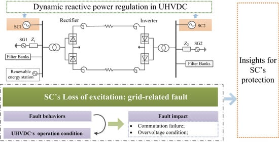
15] also verify that the SC could satisfy the two typical reactive power demands of the UHVDC: 1) providing dynamic reactive power which could effectively reduce the commutation failure on the inverter side and 2) consuming the redundant reactive power to restrain the transient overvoltage on the rectifier side.
With this comes considerations of the fault and corresponding protection of SCs. As an important grid-related failure, loss of excitation (LOE) refers to the loss of the device’s excitation ability caused by the abnormal condition of its excitation circuit [
16]. Zou et al. [
17] propose that the LOE SC would absorb reactive power from the system, which may bring security problems to the UHVDC, which is sensitive to the reactive power fluctuation. Thus, the SC’s LOE first aroused attention in the relevant study.
In a synchronous generator (SG) with a similar structure to SC, LOE has always been a research hotspot which has seen a great deal of progress. Besides the reactive power absorption, the LOE SG would be out of step and even lead to system oscillation [
18]. Using this asynchronous feature, Yaghobi [
19] proposes the most popular criteria based on the impedance technique, for example, the asynchronous limit impedance circle and steady-state stability limit impedance circle, to detect the LOE fault. Because the SG can only provide reactive power rather than absorbing it from the system, the reverse reactive power of the SG could also be used for LOE identification [
20]. Besides, other techniques including the excitation voltage/current-based technique [
21], intelligence based technique [
22] and flux based technique [
23] are also considered. Note that the latter techniques have not been widely used in the industry due to their poor accuracy and feasibility.
However, there are some obvious differences between the SC and SG in the LOE feature and impact on the system. Li et al. [
24] indicate that the LOE SC would not be in the asynchronous state like the post-fault SG. Consequently, the following two issues exist for the SC’s LOE protection.
(1) In fault identification, the traditional impedance criterion is no longer applicable to the SC. Additionally, the reverse reactive power feature could not be used to detect the LOE, because a normal SC could also absorb reactive power on some occasions, as mentioned before.
(2) In operation mode, different to the tripping operation of the SG’s LOE protection, the LOE SC may have more options considering its conceivable diverse impacts on UHVDC. Specifically speaking, the LOE SC’s effect on UHVDC mainly depends on the reactive power consumption since it can operate synchronously. As previously described, on the one hand, the reactive power deficiency caused by the LOE SC may do harm to the UHVDC, especially at the inverter end where commutation failure easily occurs. On the other hand, in the rectifier’s overvoltage condition, the reactive power consumption of the LOE SC may still be beneficial to the UHVDC’s transient stability. Therefore, for UHVDC’s different conditions, the LOE SC may have different impacts on the system.
In these contexts, the comprehensive analysis of the LOE fault features and the explicit cognition of the LOE SC’s impact on the UHVDC are urgently needed as the premise of the protection’s criterion and operation selections in view of the demands of the power grid planning and operation departments. To that end, this paper makes the following contributions.
(1) Proposing the SC’s LOE fault features. The SC’s LOE process was studied in a single-machine infinite bus (SMIB) system. Fault features, including reactive power absorption, monotonous decline of excitation current, and synchronous operation, are proposed. This can lend a basic acknowledgment of the LOE SC.
(2) Analysis of the LOE SC’s reactive power response to the system voltage variation. The LOE SC’s instantaneous reactive power response to the system voltage variation was analyzed and verified in an SMIB system. This reactive power response, which changes negatively with the system voltage, implies that the faulty SC may still have a certain effect on suppressing voltage fluctuation. This adds to the theoretical foundation for the latter research on transient UHVDC.
(3) Evaluation of the LOE SC’s impact on UHVDC’s performance. Considering the system’s different operational conditions, AC strengths, and system fault types, the LOE SC’s impact on UHVDC’s performance was comprehensively analyzed based on the simulation in PSCAD/EMTDC (V4.6, Manitoba HVDC Research Center, Winnipeg, MB, Canada). This offers some primary suggestions for the SC’s LOE protection in UHVDC. Note that compared with analytical methods, the EMTDC simulation is more suitable for the analysis of UHVDC’s performance based on the effect of various factors due to the accurate modeling of the transient process of the system, for example, the commutation failure.
The remainder of this paper is organized as follows.
Section 2 focuses on the fault features of an LOE SC.
Section 3 presents the analysis of the LOE SC’s response to the system voltage variation.
Section 4 analyzes the LOE SC’s impact on steady-state UHVDC’s performance. In
Section 5, we describe the simulations that were conducted to verify the impact of the LOE SC on the performance of transient UHVDC.
Section 6 proposes suggestions for LOE protection based on the above analyses. Finally, conclusions are provided in
Section 7.
2. SC’s Loss of Excitation Fault and Its Features
This section provides an overall insight of the LOE fault in SC. The model of the LOE SC is established in
Section 2.1. On this basis, the fault features are proposed through the theoretical analysis of the SC’s behavior during the LOE process in
Section 2.2.
Section 2.3 further verifies the results through the SMIB simulations and an engineering experiment.
2.1. Model of the LOE SC
The SC’s self-shunt excitation system consists of the excitation winding, the controlled voltage source (which could be further decomposed into the silicon-controlled rectifier and the excitation regulator), and the de-excitation circuit [
25]. Its equivalent physical model is depicted in
Figure 1.
presents the output value of the controlled voltage source,
and
represent the excitation voltage and current, respectively. The field discharge switches (
and
) and the de-excitation resistor
(its resistance is usually 2–5 times of the excitation resistance) comprise the de-excitation circuit. During the normal operation, switch
is closed as
opens (the equivalent loop is
). However, with the operation of the field discharge switch,
is open and
is closed (the equivalent loop is
).
LOE is defined as the loss of the magnetic field produced by the excitation winding. A variety of accidents could lead to this fault, such as a short-circuit or open-circuit in excitation winding, the incorrect tripping of the field discharge switch, the breakdown of the excitation rectifier or regulator and so on.
Two representative kinds of LOE fault, namely, open-circuit and short-circuit loss of excitation (referred as OLOE and SLOE, respectively), are considered in this paper:
From the physical model point of view, the parameters of the post-fault excitation loop resulting from the two kinds LOE are different. It is conceivable that the time constant of the excitation loop in an OLOE SC is smaller than that in an SLOE SC due to the existence of the de-excitation resistance.
On the basis of the above analysis, the SMIB system depicted in
Figure 2 was established in PSCAD/EMTDC. The parameters of the practical SC in engineering are shown in
Table 2. The SC models used in this paper were all built based on these actual parameters. It is supposed that there is no reactive power exchange between the system and the SC during the normal operation, and this was adopted in the practical engineering [
27]. Besides, as a result of the SC’s no-load operation, the power angle (
) is about zero during its operation. Moreover, the constant terminal voltage strategy was used in the regulator to ensure the normal SC’s corresponding forced or reduced excitation, according to the different system voltage variations.
2.2. Features Analysis of the LOE SC
Since the SC’s braking torque is very small due to its no-load operation, the additional synchronous torque, which results from the different values of the SC’s d- and q-axis reactance, is enough to conquer the braking torque to maintain the LOE SC’s synchronous operation. This assertion is also proved in practical operation.
The changing processes of the SC’s electrical quantities with the LOE fault are further analyzed theoretically. The system voltage is assumed to be constant in this section to focus on the change caused by LOE. As usual in SG analysis, the stator resistance and the transformer leakage reactance are ignored. All notations are expressed in pu in the analysis below.
For the SC, the following expressions hold:
where
and
are the
d- and
q-axis components of the terminal voltage;
and
are the
d- and
q-axis components of the terminal current; and
is the reactive power.
According to the electric machine theory [
28], the basic equation of the SC’s rotor loop can be expressed as
where
is the excitation flux, which remains invariant at the moment of LOE; and
,
and
are the excitation voltage, current and resistance, respectively.
Considering the interaction between the excitation winding and stator winding, we have the following expressions:
where
and
are the stator internal potential and transient internal potential, respectively;
is the reactance of the excitation winding; and
is the mutual reactance between excitation winding and stator winding.
By substituting Equations (5) and (6) into Equation (4), the basic equation could be written as:
From Equation (7), the
d-axis component of the SC’s stator current can be derived as
where
represents the decay time constant of the stator transient current.
The excitation current could be derived by substituting Equation (8) into Equation (6) as
Further, the reactive power of the SC can be written as
From Equations (9) and (10), the excitation current and reactive power would decrease monotonously due to the LOE fault. It should be noted that for different LOE faults, the duration of this transient process is different. Specifically, the quantities in SLOE SC would experience a longer attenuation process than those in OLOE SC.
In conclusion, the LOE fault would continue synchronous operation while resulting in the monotonous declines in excitation current and reactive power. The reactive power consumption may result in the instability of the system, which is also the most concerning consequence of the fault. Besides, compared with the SLOE SC, the quantities in OLOE SC have a shorter decline process.
2.3. Simulation Verification
To verify the fault features, the simulations of the two LOE faults occurring at 2 s in the SMIB system were conducted in PSCAD/EMTDC, respectively. The excitation current
and reactive power
are shown in
Figure 3 and they are expressed in unit values.
A visual inspection of
Figure 3 shows that the LOE SC maintains synchronous operation while the two quantities decrease monotonously after the fault. Furthermore, the electric quantities of the OLOE SC fall more rapidly compared with those of the SLOE SC. This is as expected since the time constant of the excitation loop in the OLOE SC is smaller.
In addition, a series of recorded waveforms, as shown in
Figure 4, were used to prove these conclusions. These waveforms are from an engineering experiment in which mal-operation of the field discharge switch occurred. The excitation current
here is a transduced value. It has fluctuations during the LOE process due to the arc discharge of the field discharge switch.
represents the terminal phase current of the SC, it has a significant increase after the fault. This implies that the SC’s internal potential declines with the reduction of the excitation current, which further results in reactive power consumption.
3. Analysis of the LOE SC’s Response to System Voltage Variation
According to the above analysis, the LOE SC would absorb reactive power. However, it may still be beneficial to the UHVDC under the overvoltage condition. In order to clarify the influence of the LOE SC on the transient UHVDC, the analysis of the dynamic response of the LOE SC to the system voltage variation is necessary. The theoretical analysis of the LOE SC’s reactive power response to the system voltage variation is carried out in
Section 3.1. and
Section 3.2 verifies this response through the simulations in the SMIB system.
3.1. Theoretical Analysis of the LOE SC’s Response to Voltage Variation
As mentioned, an SC is essentially a no-load SG, so the fundamental motor theory is also applicable to the study of the SC. Before the analysis, a few things should be noted. Firstly, the SC’s excitation regulator could not work normally due to the LOE fault, thus its role in this transient process can be ignored. Secondly, the stator resistance and transformer leakage reactance are ignored during this process as previously done. Moreover, as the worst condition, the LOE SC is assumed to be in its maximum phase-in condition before the system voltage changes. The following notations are expressed in pu.
According to the Park equation [
28], the increment of
during the change of system voltage can be expressed as
where
represents the variation of the system bus voltage;
represents the pre-fault value while
represents the post-fault value;
represents the time constant of stator sub-transient current;
represents the time constant of the stator current aperiodic component; and
represents the electric angular velocity of the SC; there is
for SC because of its no-load operation.
Furthermore, the reactive power of the LOE SC during the system’s transient process can be derived from Equation (11) as
where
represents the LOE SC’s stator current value before the system voltage changes. Since the LOE SC absorbs reactive power, in other words,
,
is the reactive power value before the system voltage changes and it can be derived from Equation (10) that
.
As can be seen from Equation (12), the reactive power response of the LOE SC consists of the decaying DC component①, the decaying AC component②, and the steady-state component③. The instantaneous post-fault value is determined by the three components and then the reactive power would finally decay to the steady-state component.
For clarification, the instantaneous value, the decay rate and the steady value of this reactive power are analyzed respectively:
• Instantaneous value of the reactive power.
With
, the instant variation of
can be expressed as
With Equation (13), the reactive power increment can be expressed as
where
is the instantaneous reactive power value of the LOE SC after the system voltage changes.
As can be inferred from Equation (14), the change tendency of reactive power ( ) is opposite to that of the system voltage ( ) with . This further indicates that the instantaneous reactive power response of the LOE SC is in line with the system demands. In particularly:
(a) In the overvoltage state ( ), the LOE SC will consume more reactive power ( ) considering and .
(b) In the low bus voltage state (
), the value of
needs a deeper discussion considering
and
. By substituting the parameters of the SC in
Table 2 into Equation (14), it can be derived that when
,
. In addition,
reaches its maximum when
.
• The decay rate of the reactive power.
The first two components of Equation (12) decay with their respective time constants, in which
is related to the excitation loop. For different LOE SCs, as described in
Section 2, the OLOE SC has a shorter transient process compared with the SLOE SC.
• The final value of the reactive power.
The final value of the reactive power is determined by the third steady-state component, which could be expressed as
(a) In the overvoltage situation, considering and . That is, the LOE SC keeps consuming reactive power in this condition.
(b) In the low voltage situation, it can be derived that when by substituting the SC’s parameters.
In summary, it can be concluded that the LOE SC still has an instantaneous reactive power response to the system voltage variation, which is contrary to the system voltage change and decays with time. Compared with OLOE, the attenuation process of reactive power in SLOE is longer.
Correspondingly, the primary conclusions regarding the LOE SC on transient UHVDC are as follows:
The LOE SC could absorb reactive power continuously during the overvoltage condition;
The LOE SC may provide some reactive power when the system experiences a large voltage drop, while under most of these conditions; the LOE SC still absorbs reactive power in the low system voltage condition.
3.2. Simulation Verification
LOE SC’s responses to the system voltage rise and drop were simulated respectively in the SMIB system. The LOE fault occurred at 2 s (both OLOE and SLOE are considered), while the system voltage changes from 1.0 pu to 1.2 pu, 0.7 pu and 0.2 pu (referred to as 1.2SLOE/OLOE, 0.7SLOE/OLOE and 0.2SLOE/OLOE) at 4 s, respectively. As the result of the limited space, the SC’s LOE process depicted in
Figure 3 is no longer presented here. The reactive power response of the LOE SC during the change of system voltage is shown in
Figure 5.
As expected, the LOE SC still has an instantaneous reactive power variation at the moment of the system voltage change, which is positive under the voltage drop condition and negative under the voltage rise condition. The OLOE SC’s reactive power has a shorter attenuation process compared with the SLOE SC under the same voltage variation, which is as illustrated above.
Under the overvoltage condition (1.2SLOE/OLOE, as shown in
Figure 5), the LOE SC could consume the reactive power continuously as expected. It is conceivable that the LOE SC would have a definite positive impact on the system under the overvoltage condition.
Under the low voltage conditions depicted in
Figure 5 (0.7SLOE/OLOE and 0.2SLOE/OLOE), as expected, the LOE SC emits reactive power at the instant of voltage change in the two scenarios. In the 0.2 pu scenario, the LOE SC continuously provides reactive power which is helpful to the transient system while in the 0.7 pu scenario, the LOE SC finally absorbs the reactive power. The specific impact of the LOE SC on the low system voltage condition will be further illustrated through the actual UHVDC simulation later.
5. Impact of the LOE SC on the Performance of Transient UHVDC
Since the LOE SC still has instantaneous reactive power response to the system voltage variation, which is described in
Section 3, this section discusses the LOE SC’s impact on the transient UHVDC through the practical performance simulation in UHVDC. The system performances, such as DC transmission power, commutation bus voltage and the connecting WTG’s transmission power, are compared between the case with the LOE SC and the case without the LOE SC to illustrate the impact.
The UHVDC model depicted in
Figure 6 was used for simulation. For a comprehensive analysis, the two typical transient conditions of the UHVDC, namely the inverter bus low voltage caused by an AC fault and the rectifier bus overvoltage caused by a DC fault, were conducted, respectively. The SC’s LOE fault occurs at 2 s, then the other system fault resulting in the converter bus voltage fluctuation occurs at 5 s. Consistent with the theoretical analysis, the LOE SC has been its maximum phase-in depth before the system fault. With these considerations, the following simulation analyses were conducted in PSCAD/EMTDC software.
5.1. Impact on the UHVDC under Inverter Low Voltage
As the most serious AC fault, the three-phase short circuit with different transition resistances (174.36 Ω in Scenario 1 and 182.21 Ω in Scenario 2) were applied on the inverter side to cause the bus voltage sag. It is conceivable that the larger the transition resistance, the larger the post-fault system voltage, and the less likelihood of commutation failure. Hence, Scenario 1 is more prone to commutation failure than Scenario 2.
In each fault location scenario, the system’s performance is further compared under the three conditions, namely, the case keeping the LOE SC caused by the discharge switch’s mal-operation (referred to as Ncut), the case separating the LOE SC after the system fault (referred to as Cut1) and the case separating the LOE SC after the LOE fault (referred to as Cut2).
The visual inspection of
Figure 8 indicates that in Scenario 1, compared with the other two cases (Ncut and Cut2) where commutation failure occurs, the case separating the LOE SC after the system fault (Cut1) has the best performance, in other words, no commutation failure occurs. In Scenario 2 with the smaller probability of the occurrence of commutation failure, the commutation failure does not appear in Cut1, as is expected. However, commutating failure occurs in the Cut2 case, while no commutating failure appears in the Ncut case. This implies that for the low bus voltage transient on the inverter side, separating the LOE SC after the voltage drop is the most effective way to avoid the commutation failure, and the connecting LOE SC is also still beneficial to the system’s transient operation even though it absorbs reactive power, as compared with separating the SC immediately after LOE.
This abnormal phenomenon is mainly related to commutation failure. Lin et al. [
29] indicate that in the process of commutation failure caused by an AC fault, aside from the absolute value of bus voltage, the voltage drop speed also has a large effect on the commutation process. In the Ncut case, although the LOE SC always absorbs reactive power resulting in a lower bus voltage value compared with the Cut2 case, the LOE SC still provides a positive reactive power increment at the instant of system fault, which slows down the process of bus voltage drop, thus avoiding commutation failure to a certain extent.
In the same way, since the instantaneous reactive power increment provided by the LOE SC is less than that provided by separating the LOE SC after the system fault (which can be seen from the reactive power diagram in
Figure 8), Cut1 is the way that contributes the most to avoiding commutation failure.
To verify the illustration, more simulations were carried out in the system with the inverter AC SCR varying from 2 to 8. The commutation failure immunity index (CFII) proposed in [
30] was used here to evaluate the vulnerability of the commutation failure in these three cases. The mathematical expression of CFII is depicted as:
where
presents the line voltage rating of the commutation bus;
presents the DC transmission power rating and
presents the maximum fault impedance that would cause the commutation failure. It is conceivable that the smaller the CFII, the greater the possibility of commutation failure. The result is presented in
Table 4.
From
Table 4, under the Cut1, Ncut and Cut2 conditions, the corresponding CFII decreases in turn. In other words, it can be concluded that compared with separating the SC immediately after LOE, connecting the LOE SC is still beneficial for the inverter low voltage transient, while the most effective operation to reduce commutation failure is separating the LOE SC after the system voltage drop. On the basis of the above conclusions, the appropriate operation modes of the SC’s LOE protection are discussed further in the later sections.
5.2. Impact on the UHVDC under Rectifier Overvoltage Fault
This part focuses on the rectifier overvoltage fault caused by a DC ground fault resulting in power interruption, which may further induce a WTG’s tripping fault. The SC’s reactive power output, rectifier bus voltage and the WTG’s active power output were recorded and compared between the Ncut, Cut1 and Cut2 cases.
As shown in
Figure 9, the LOE SC has a negative reactive power increment when the converter bus experiences a voltage rise, which is as expected. With the reactive power absorption, the bus voltage and WTG’s active power performances in the Ncut case are better than the cases separating the LOE SC (Cut1 and Cut2). The system performances in the two cases (Cut1 and Cut2) are basically the same.
Thus, it can be concluded that the LOE SC could also absorb reactive power during the period of overvoltage fault, which helps to restrain the transient overvoltage. This may efficiently reduce the occurrence of the high-voltage tripping fault of renewable energy.
5.3. Summary
The impact of the SC’s LOE fault on the transient system’s performance can be summarized as follows.
On the inverter side, compared with separating the LOE SC immediately, keeping the LOE SC may still be beneficial to decrease the commutation failure due to the instantaneous positive reactive power increment; furthermore, separating the LOE SC after the system voltage drop has the best performance.
The rectifier LOE SC is also still beneficial for restraining the bus overvoltage, which may have a significant effect on the decrease in renewable energy tripping.


