Article

Fault Current Limiting and Breaking Characteristics of SFCLB Using Flux Coupling with Tap Changer

1
Department of Electrical Engineering, Soongsil University, 369, Sangdo-ro, Dongjak-gu, Seoul 156-743, Korea
2
Department of Mechanical Engineering, Soongsil University, 369, Sangdo-ro, Dongjak-gu, Seoul 156-743, Korea
3
Department of Organic Material and Fiber Engineering, Soongsil University, 369, Sangdo-ro, Dongjak-gu, Seoul 156-743, Korea
*
Author to whom correspondence should be addressed.
Energies 2020, 13(19), 5138; https://doi.org/10.3390/en13195138
Submission received: 17 August 2020 / Revised: 24 September 2020 / Accepted: 27 September 2020 / Published: 2 October 2020
(This article belongs to the Section F: Electrical Engineering)

Abstract

:
In this paper, a superconducting fault current limiting breaker (SFCLB) using flux coupling with a tap changer is suggested and its effective fault current limiting and breaking characteristics due to the winding method using its tap changer are analyzed. The suggested SFCLB using flux coupling, which consists of the SFCLB using flux coupling with a tap changer, mechanical switch and driving coil, can perform the circuit-breaking function without external driving power after the fault current limiting operation. To examine the suggested SFCLB’s operation, the small scale SFCLB using flux coupling was fabricated and alternative current (AC) short-circuit experiments due to the winding method using the tap changer of the SFCLB were executed. From the experimental results, a lower fault current limiting rate and faster breaking time in the case of a SFCLB with a series connection could be obtained compared to one with a parallel connection.

1. Introduction

In overcoming the technical limitation of previous protective devices, such as the circuit breaker, series reactor and power fuse, superconducting fault current limiters (SFCLs) have received attention as promising devices [1,2,3,4]. Moreover, the increased fault current due to increased power generation facilities with a larger capacity and the meshed system construction have accelerated the development of various types of SFCLs for application in the real field system [5,6,7,8,9,10,11]. Among the developed SFCLs, the trigger or hybrid type SFCL has been reported to be more effective in highly reducing the volume or amount of the superconducting (HTSC) elements comprising the SFCL, which has given the SFCL a lower cost by using a mechanical switch (MS) [10,11,12,13,14,15,16,17]. Of the other types of SFCL, an SFCL using flux-coupling between the windings wound on one iron core has been studied. With a tap changer or adjustment of the turn ratio comprising the SFCL, the operating current of the SFCL can be easily set higher or lower than the critical current of the HTSC element and this reduces the power burden of the HTSC elements, thus decreasing the number of HTSC elements comprising the SFCL as well [17,18,19,20,21,22,23,24,25].
Continuously, a flux-lock type SFCL using a mechanical switch, which utilizes the features of the trigger type and flux-coupling type SFCLs, has been reported upon and its advantageous characteristics described compared to other types of SFCL. Recently, the operational characteristics of the SFCL with an interrupting operation have been presented [26,27]. The interrupting operation of the SFCL is expected to be more necessary for the reliable operation of the meshed or looped power system with multiple bus lines and the protection of linked power systems from the short circuit [28,29,30].
Generally, for the interrupting operation or the breaking operation of the circuit breaker (CB) and the power switch (PS), installed for separation from the abnormal state of the power system, an additional driving circuit and power source for the opening of the CB are commonly required together with either a current or voltage transformer [31,32].
In this paper, a superconducting fault current limiting breaker (SFCLB) using flux coupling with a tap changer, which is not required for additional driving power, was suggested, and its parallel and series constructions through the tap changer were designed. Through short-circuit tests for a small-scale fabricated SFCLB, its fault current limiting and breaking characteristics dependent on the winding method of the coils were analyzed.

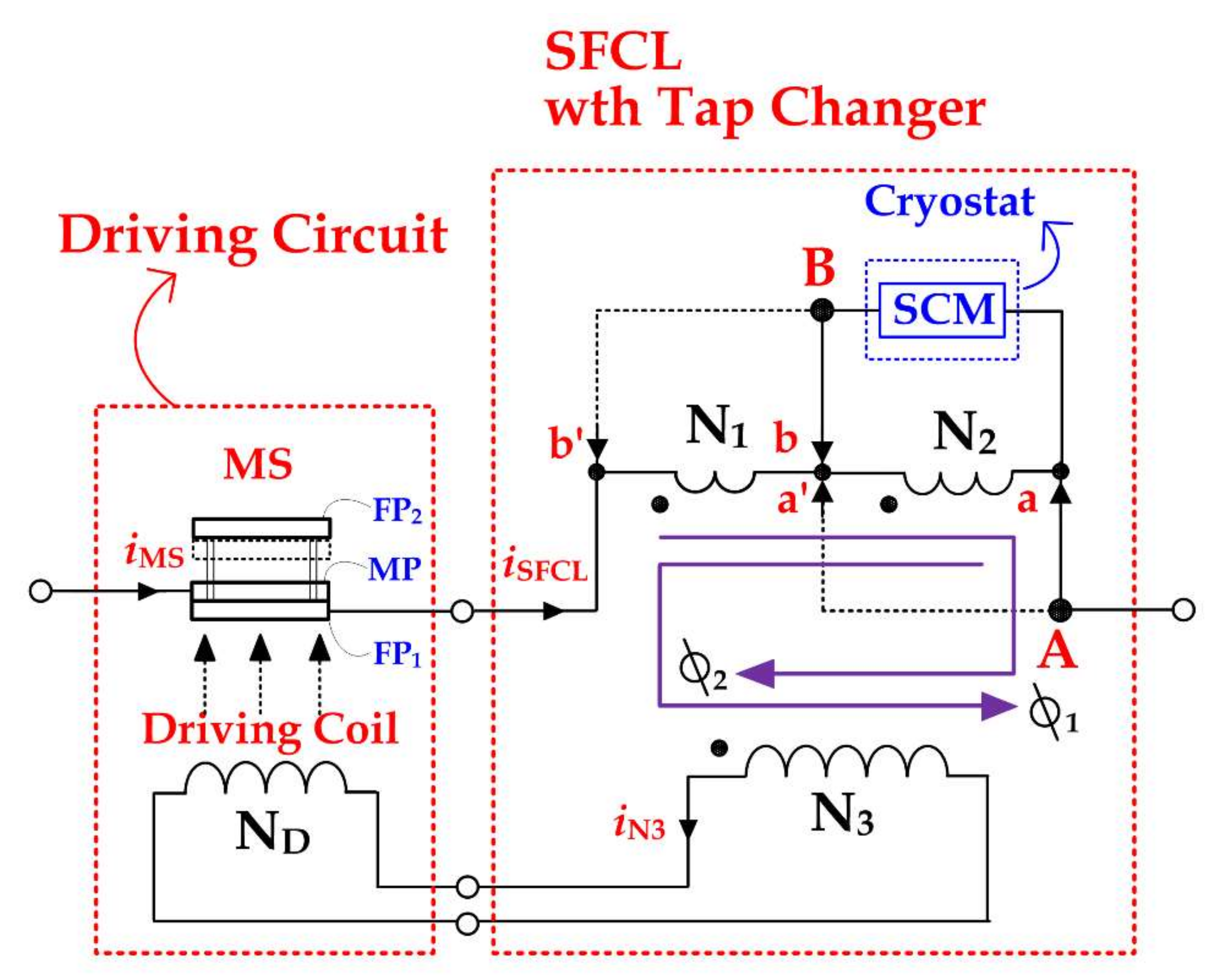
2. Structure and Operational Principle

2.1. Structure

The proposed SFCLB using flux coupling with a tap changer mainly consists of the SFCL with a tap changer to switch the winding method and a self-driving circuit for the breaking operation (driving coil and MS), as shown in Figure 1. The SFCL with a tap changer is composed of three magnetically coupled coils (N1, N2, N3) wound on the same iron core. A and B taps can be moved from a and b into a’ and b’ within each coil (N1, N2). In the case that A and B taps are connected into a and b as seen in Figure 1, the two coils of the SFCL are constructed as a series connection. In the case that the A and B taps move into a’ and b’, the two coils of the SFCL are designed as a parallel connection.
The superconducting module (SCM), which is located within cryostat filled with liquid nitrogen, is connected to two taps. The N3 coil, apart from the N1 and N2 coils, is connected to the driving coil (ND).
The self-driving circuit consists of the driving coil, wound on the cylindrical bobbin, and the MS. The MS includes the moving plate (MP) and two fixed plates (FP1, FP2) with a constant distance by four guide bars.

2.2. Operational Principle

When the SCM is in the superconducting state as seen in Figure 1, the current in the driving coil does not generate if the coil’s resistance and the leakage flux between coils can be ignored, because two fluxes (φ1, φ2) from two coils cancel each other out. Therefore, in a normal time, when the magnetic flux for the magnetic repulsive force on the MP does not generate, the MP keeps the contact with the FP1.
However, the quench generation in the SCM right after the fault occurs does not allow the cancellation between two fluxes, which gives rise to a limit in the fault current and contributes to the fault current limiting operation of the SFCLB [19,20,21,22,23,24,25,26,27]. Simultaneously, the induced voltage in the N3 due to the non-cancellation of two fluxes brings the current flow into the driving coil. The current flow in the driving coil, wound on the cylindrical plastic bobbin, induces the magnetic flux of the axial direction into the MP. If the electromagnetic repulsive force generated by the magnetic flux on the MP exceeds the gravity force of the MP, the MP moves from the FT1 into the FP2, which contributes to the fault current breaking operation of the SFCLB without the additional driving power supplier.
The larger induced current in the driving coil directly after the fault occurrence is expected to cause the larger magnetic flux of the axial direction on the MP and the larger electromagnetic repulsive force. In addition, the larger induced current in the driving coil is proportional to the axial direction moving velocity of the MP due to a larger electromagnetic repulsive force, which is related to the opening time of the MS.
Figure 2 shows the phases of total clearing time in the general circuit breaker (CB). The opening time means the period until the CB opens after the trip coil is energized. The arching time represents the period until the current of the CB is fully zero after the opening operation of the CB starts. The breaking time is equal to the sum of the opening time and the arching time [33].
The induced current in the driving coil, as well as the opening time of the MS comprising the suggested SFCLB using flux coupling, is expected to be dependent on the winding method of two coils among its main design parameters. To switch the winding method, the locations of two taps (A, B) were changed with the tap changer. One case is that the two taps are located on a and b points of two coils, which is called a series connection because it seems like a series connection of two coils. The other case is that the two taps are located on a’ and b’ points of two coils, which is called a parallel connection from the parallel connection of the two coils.
Figure 3 shows the electrical equivalent circuits of the SFCLB using flux coupling for the two winding methods as described above. In each equivalent circuit, the magnetizing inductance (Lm) was included with a consideration for the magnetizing characteristics during the fault period.

3. Experimental Setup

The design specification of the SFCLB using the flux coupling with a tap changer was listed in detail in Table A1, Appendix A. For the SCM with a larger critical current, three superconducting elements with the same critical current were connected in parallel. As two winding methods using the tap changer, the series connection (where the two taps are located on a’ and b’ points) and the parallel connection (where the two taps are located on a and b points) were constructed as shown in Figure 1. Figure 4 shows the schematic experimental test circuit with the SFCLB using flux coupling with a tap changer. In the test circuit, the input voltage (EIn) of 200 Vrms was connected with the SFCLB through an input impedance (ZIn) of 1 Ω and a load resistance (RL) of 41.2 Ω. The short-circuit fault tests were executed by closing SW2, connected in parallel with the load resistance, after closing SW1, connected in series with the input voltage, as shown in Figure 4. The currents and the voltages of the MS, SCM and coils comprising the SFCLB for each winding method were recorded into the data acquisition system after measuring through the current and the voltage probes.

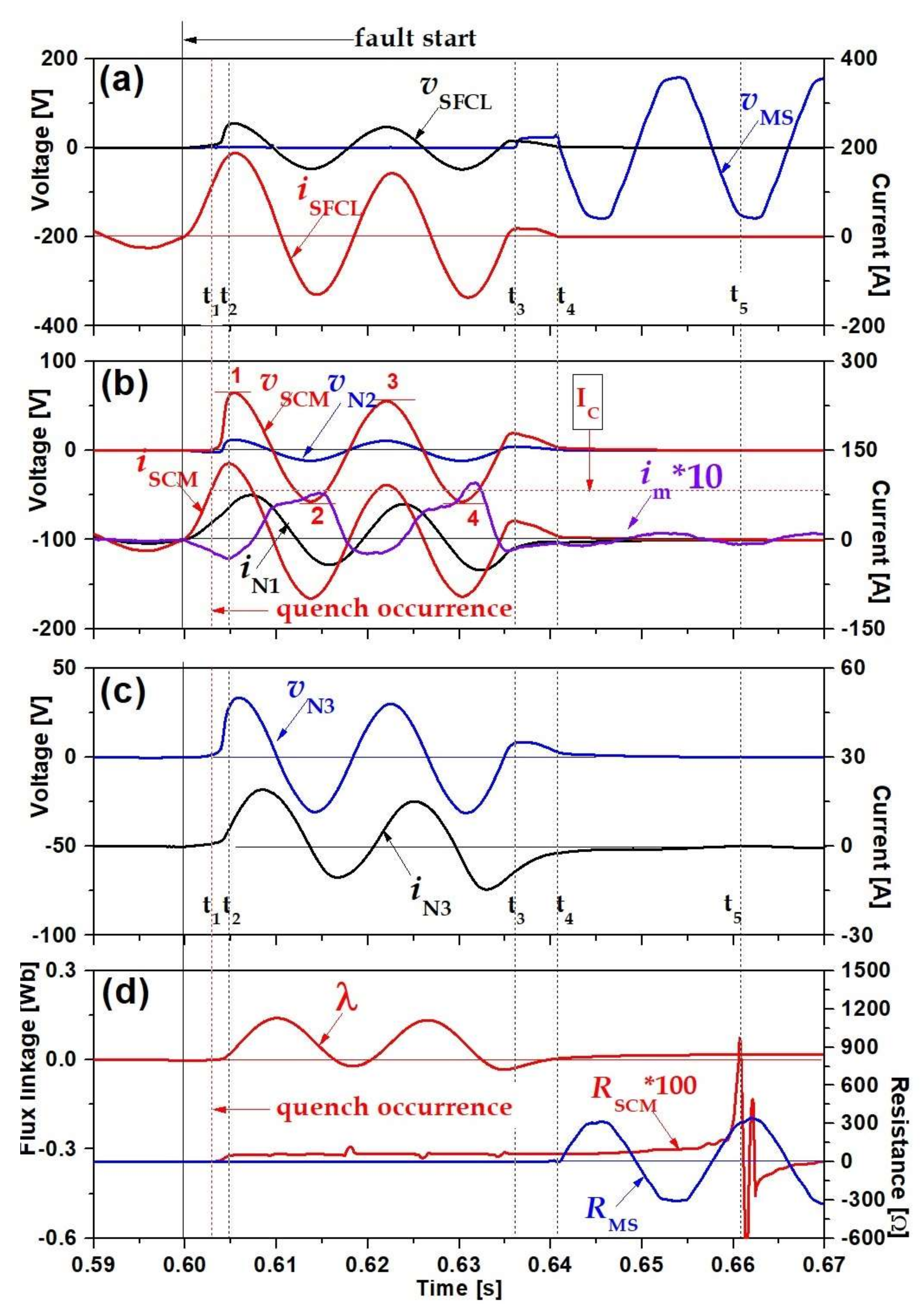
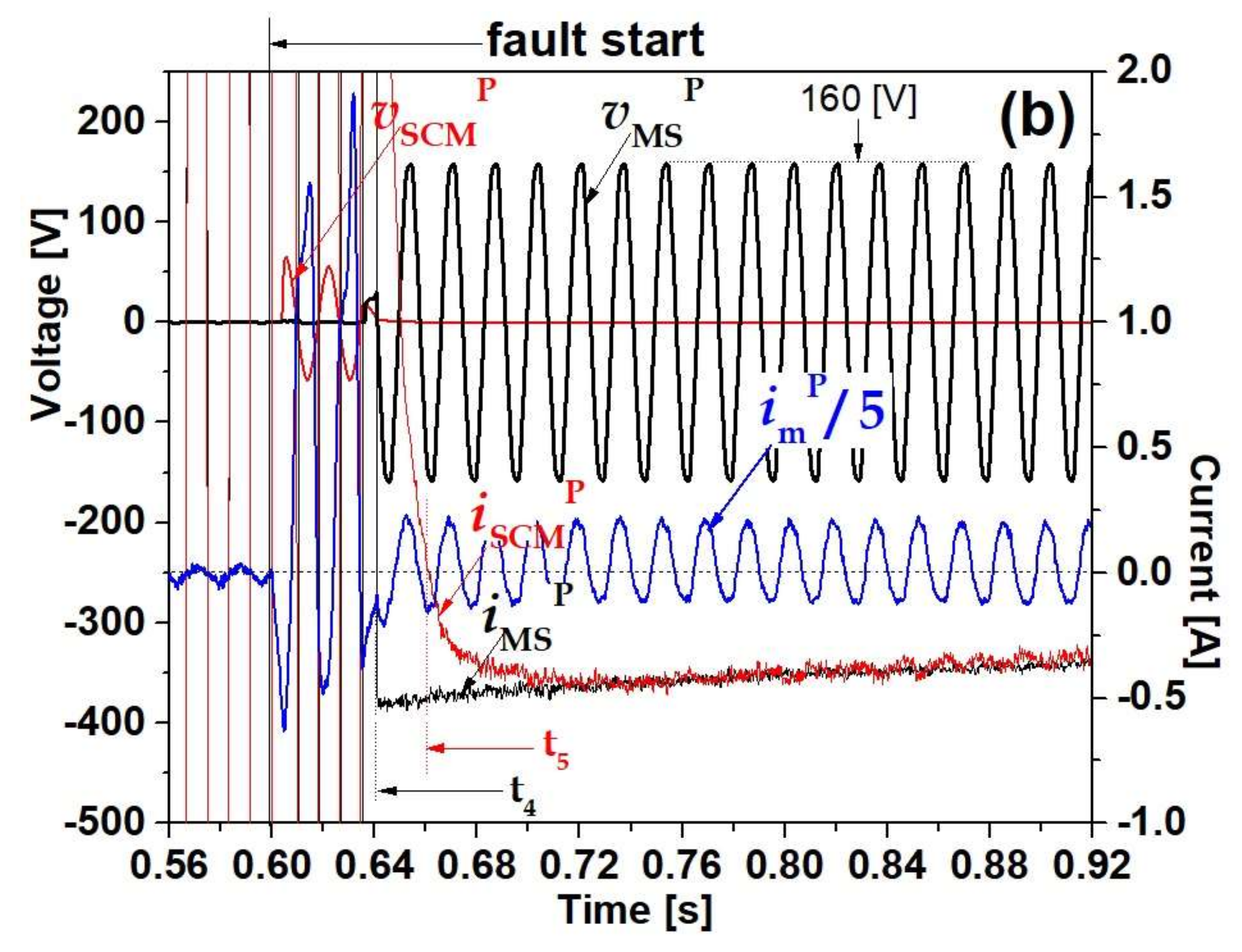
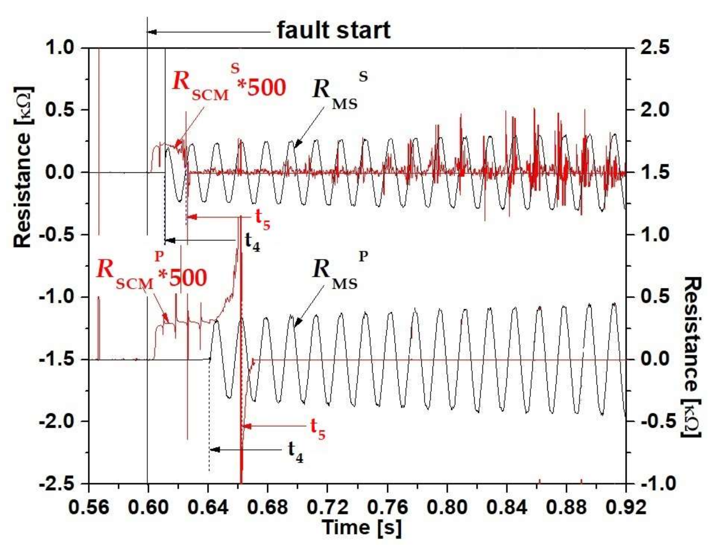
4. Results and Discussion

To investigate its breaking time, including the opening time due to its winding method, the fault current limiting and breaking characteristics of the suggested SFCLB using flux coupling were analyzed. Generally, a larger driving current is advantageous for the fast opening operation of the SFCLB.
Figure 5 shows the fault current limiting and breaking operational sequence of the SFCLB using flux coupling with a tap changer due to the two winding method. The time to reach the critical current (IC) of the SCM after the fault occurred was marked t1, which is equal to the time of the quench occurrence of the SCM. In the case of Figure 5a with the winding method in the series connection, the time to rise to the critical current of the SCM is faster than in the case of the parallel connection, as compared with Figure 5b. After t1, the time it took for the SCM’s current (iSCM) to arrive at its first peak value was indicated with t2. Despite the faster arrival at the critical current of the SCM in the case of the series connection (Figure 5a), the first peak value of the current in the SCM can be observed as being larger than in the case of the parallel connection (Figure 5b). The time that the breaking operation of the SFCLB starts is indicated with t3 in Figure 5. The breaking operation starting time can be checked by the voltage generation across the MS (vMS).
After the breaking operation starts, the current in the MS drops and then approaches almost a zero value as marked with t4 in Figure 5. The time until the current in the MS drops to a zero value after t3 is defined as the opening time of the circuit breaker as explained in Figure 2. Regardless of the winding method, the opening time of the SFCLB using flux coupling had little difference as compared with Figure 5a,b. On the other hand, before the breaking operation starts, the fault current limiting operation period between t1 and t3 had more of a difference due to the winding method. In the SFCLB using flux coupling constructed as a series connection, the fault current limiting operation period was observed to be shorter than in the one constructed as the parallel connection. After the opening time finished (t4), the time in which the current of the SCM approached zero value (iSCM) is displayed with t5. As compared in Figure 5a,b for each winding, the time it took for the SCM’s current to approach a zero value after t4 was observed to take a longer time in the case of the parallel connection than in the case of the series connection.
To investigate the different opening starting times due to the winding method, the flux linkage, the driving current and the resistance in the SCM were compared. Figure 6 shows the fault current limiting and breaking operational waveforms of the SFCLB using flux coupling with a tap changer in the case of the series connection. The voltage of the SFCL (vSFCL) in Figure 6a is seen to be the sum of the voltages of the coil N1 and the SCM (vN1 + vSCM) in Figure 6b. The current of the SFCLB (iSFCL) in Figure 6a, which is observed to be cut off after the opening time (t4) finishes, is also observed to be divided into both the current of the coil N2 (iN2) and the current of the SCM (iSCM) as seen in Figure 6b. The above relationship of the voltage and the current comprising the SFCLB is confirmed as agreeing well with the analysis obtained from the electrical equivalent circuit as shown in Figure 3a, assuming that the magnetizing current (im) is ignored.
The flux linkage (λ) in Figure 6d, which was calculated from the induced voltage at the driving coil Nd (i.e., the voltage of the N3 coil (vN3) in Figure 6c), increases and reaches the peak value shortly after the opening operation of the SFCLB starts (t3). After the opening operation finishes (t4), the voltage across the MS (vMS) comprising the SFCLB, which starts to be induced after t3, can be observed to keep a sinusoidal waveform with constant amplitude as seen in Figure 6a. In addition, the resistance of the MS (RMS), as displayed in Figure 6d, is also seen to have a sinusoidal waveform directly after the plus and minus peaks generate near t4. However, after t4, its peak value has a smoothly increasing tendency. Furthermore, when the decreased current in the SCM approaches a zero value near t5, the resistance of the SCM (RSCM), which was displayed by dividing the voltage in SCM (vSCM) with the current in SCM (iSCM), immediately increases into the plus value, then sharply decreases into the minus value. Shortly after that, the resistance of the SCM can be seen to be zero, as shown in Figure 6d.
Figure 7 shows the fault current limiting and breaking operational waveforms of the SFCLB using flux coupling with a tap changer in the case of a parallel connection. The voltage of the SFCL (vSFCL) in Figure 7a is the same as the voltage of the coil N1 (vN1) as analyzed from the electrical equivalent circuit in Figure 3b. However, the amplitude of the SFCL’s voltage (vSFCL) in the parallel connection is lower than that in the series connection. Due to the winding polarity of the parallel connection, the voltage of the SCM (vSCM) is analyzed as being equal to the voltages’ sum in coil N1 and coil N2 (vN1 + vN2) in Figure 7a,b. In the parallel connection, the current of the SFCLB (iSFCL) in Figure 7a, which has a larger amplitude than the series connection, is analyzed as being identical to the sum of the two currents in the coil N1 and the SCM (iN1 + iSCM) in Figure 7b if the magnetizing current (im) is not considered.
The flux linkage (λ) in Figure 7d in the parallel winding slowly increases after the current of the SCM (iSCM) reaches its first peak value (t2) and has a lower peak amplitude than in the case of the series connection, as shown in Figure 6d. The lower amplitude of the flux linkage, which results from the lower amplitude of the N3 coil’s voltage or the Nd driving coil (vN3), contributes to a longer starting time for the opening operation in the SFCLB (t3), as seen in Figure 7.
After the opening operation finishes (t4), the voltage across the MS (vMS) and the resistance of the MS (RMS) with sinusoidal waveforms are observed as displayed in Figure 7a,d. The resistance of the SCM (RSCM), which repeats the sharply increased plus and decreased minus values near t5, is seen to smoothly decrease to zero after t5, as shown in Figure 7d.
From the comparative analyzed results coming from its winding method, the operational sequential time of the SFCLB using flux coupling is listed in Table A2.
To analyze the variation of the resistances (RSCM, RMS) in both the SCM and the MS after the fault occurrence, the voltage and the current waveforms of the SCM (vSCM, iSCM) and MS (vMS, iMS) were redisplayed with the enlargement of the current range in Figure 8 for the winding method. In the case of the series connection as seen in Figure 8a, the current flowing into the MS (iMSS), i.e., the SFCLB, is seen to be sharply decreased at the point when the opening time is completed as indicated with t4 and slowly reduces after t4. On the other hand, the voltage of the MS (vMSS) after t4 has a sinusoidal waveform with amplitude of 160 V. In the case of the SCM, the induced voltage (vSCMS) in the SCM after the fault occurrence drops to zero at t4, the time that the opening operation of the MS finishes. Together with the zero of the MS’s voltage after t4, the sharply decreased current (iSCMS) of the SCM approaches a zero value at t5. However, after t5, the noisy sinusoidal waveform in the SCM’s current with slowly decreased amplitude can be observed as seen in Figure 8a. The non-zero currents in the MS and the SCM directly after t4 are thought to be related to the magnetizing current (imS), which slowly decreases with a sinusoidal waveform after it approaches the peak value due to the fault occurrence.
In the case of the parallel connection as displayed in Figure 8b, the current of the MS (iMSP) slowly decreases with a non-sinusoidal form after it approaches zero value at t4. The current of the SCM (iSCMP), except that it approaches zero value at t5, is the same as the current of the MS.
From the current and the voltage of the MS and the SCM as analyzed in Figure 8, the resistances of the MS (RMSS, RMSP) and the SCM (RSCMS, RSCMP) for the winding methods are displayed in Figure 9. The non-zero constant voltage in the MS (vMSS, vMSP) and the slowly decreased current in the MS (iMSS, iMSP) after t4 are confirmed as causing the slowly increased resistance (RMSS, RMSP). On the other hand, the SCM’s resistance (RSCMS or RSCMP) can be seen to drop to the zero value after it increases into a higher peak value at t5, especially in the case of the parallel connection.
The residual current with the slowly decreased non-zero value in the MS after its opening operation finishes, called arching time as described in the above Figure 2, needs to be removed as fast as possible for its large scale application in the real field, because the residual current of the MS can cause its unstable opening state as well as the arc loss. In addition, the arc loss due to the residual current can cause corrosion on the plates comprising the MS, bringing about the performance degradation of the MS.
Based on this analysis, a countermeasure to decrease the arching time of this SFCLB using flux coupling can be explored in the future.

5. Conclusions

In this paper, an SFCLB using flux coupling, which performs both fault current limiting and breaking operations without an additional driving power source, was suggested and analyzed in its effective operation through short-circuit tests on a small-scale designed SFCLB owing to the winding method using a tap changer. In addition, the breaking time and opening time of the SFCLB due to its winding method were analyzed.
In the SFCLB using flux coupling designed as a series connection, the fault current limiting operation period and the time that the opening operation of the MS comprising the SFCLB finished were observed to be shorter and faster compared to the parallel connection. The shorter fault current limiting operation and the faster opening operation performance in the series connection were analyzed as resulting from the higher first peak amplitude of the flux linkage shortly after the fault occurrence.
Though the opening operation of the SFCLB using flux coupling finished after its fault current operation, the residual current in the MS was observed to keep a slowly decreased non-zero value for a long time.
For large-scale application in the real field, the countermeasure to drop fast to the zero value in the current of the MS is expected to be required in the future.

Author Contributions

S.-H.L. wrote and edited the article and conducted the experiments. J.-O.K. and Y.J. supported the experiments. All authors have read and agreed to the published version of the manuscript.

Funding

This research was supported by by the Soongsil University Research Fund of 2017 and also supported by the National Research Foundation of Korea (NRF) grant funded by the Korea government (MOE) (No. 2020R1F1A1077206).

Conflicts of Interest

The authors declare no conflict of interest.

Appendix A

Table A1. Design specification of the superconducting fault current limiting breaker (SFCLB) using flux coupling with a tap changer.
ComponentParameterValueUnit
Driving Circuit
MS (FP1, FP2, MP)Thickness3mm
Diameter of Each Plate100mm
MaterialAluminum
Distance between Two Fixed Plates mm
BobbinCylindrical Form100mm
Height
Outer Diameter120mm
Inter Diameter
Turn Number120Turns
Driving Coil (ND)Turn Number300Turns
Coupled Coils with Tap Changer
Iron CoreVertical Length of Outer Edge235mm
Height of Outer Edge250mm
Vertical Length of Inner Edge137mm
Height of Inner Edge155mm
Thickness132mm
Permeability Ratio(μr)8000–10,000H/m
Coupled CoilsTurn Number of Primary Coil (N1)45Turns
Turn Number of Secondary Coil (N2)15Turns
Turn Number of Tertiary Coil (N3)120Turns
Superconducting Module (SCM)
MaterialYBCO
Fabrication formFilm Type
Total Line Length420mm
Line width2mm
Thickness of Whole Film0.3μm
Thickness of Gold Layer0.2μm
Critical Temperature (TC)87K
Critical Current (IC)27A
Three HTSC Modules (SC1, SC2, SC3) Connected in Parallel
Total Critical Current81A
Table A2. Operational sequential time due to the winding method of the SFCLB using flux coupling with a tap changer.
Operational Sequential Timet1 (s)t2 (s)t3 (s)t4 (s)t5 (s)
DescriptionQuench starting timeApproaching time to first peak valueStarting time of breaking operationOpening time of CBApproaching time into zero value of SCM current
Series Connection0.600900.601960.605570.610880.62452
Parallel Connection0.602900.604800.636100.640720.66076

References

  1. Ye, L.; Lin, L.Z.; Juengst, K.P. Application studies of superconducting fault current limiters in electric power systems. IEEE Trans. Appl. Supercond. 2002, 12, 900–903. [Google Scholar]
  2. Jiang, Y.; Dongyuan, S.; Xianzhong, D.; Yuejin, T.; Shijie, C. Comparison of superconducting fault current limiter in power system. In Proceedings of the 2001 Power Engineering Society Summer Meeting, Conference Proceedings (Cat. No.01CH37262). Vancouver, BC, Canada, 15–19 July 2001; pp. 43–47. [Google Scholar]
  3. Lim, S.H.; Choi, H.S.; Chung, D.C.; Jeong, Y.H.; Han, Y.H.; Sung, T.H.; Han, B.S. Fault Current Limiting Characteristics of Resistive Type SFCL Using a Transformer. IEEE Trans. Appl. Supercond. 2005, 15, 2055–2058. [Google Scholar] [CrossRef]
  4. Alam, M.S.; Abido, M.A.Y.; El-Amin, I. Fault Current Limiters in Power Systems: A Comprehensive Review. Energies 2018, 11, 1025. [Google Scholar]
  5. Kovalsky, L.; Yuan, X.; Tekletsadik Keri, K.; Bock, A.J.; Breuer, F. Applications of superconducting fault current limiters in electric power transmission systems. IEEE Trans. Appl. Supercond. 2005, 15, 2130–2133. [Google Scholar]
  6. Chen, Y.; Liu, X.; Sheng, J.; Cai, L.; Jin, Z.; Gu, J.; An, Z.; Yang, X.; Hong, Z. Design and Application of a Superconducting Fault Current Limiter in DC Systems. IEEE Trans. Appl. Supercond. 2014, 24, 5601305. [Google Scholar]
  7. Naoki, H.; Yuya, M.; Hiroki, K. Fault Current Limitation Coordination in Electric Power Grid with Superconducting Fault Current Limiters. IEEE Trans. Appl. Supercond. 2018, 28, 5602304. [Google Scholar]
  8. Martini, L.; Bocchi, M.; Angeli, G.; Ascade, M.; Rossi, V.; Valzasina, A.; Ravetta, C.; Fratti, S.; Martino, E. Live Grid Field-Testing Final Results of the First Italian Superconducting Fault Current Limiter and Severe 3-Phase Fault Experience. IEEE Trans. Appl. Supercond. 2015, 25, 5600405. [Google Scholar] [CrossRef]
  9. Song, M.; Tang, Y.; Zhou, Y.; Ren, L.; Chen, L.; Cheng, S. Electromagnetic Characteristics Analysis of Air-Core Transformer Used in Voltage Compensation Type Active SFCL. IEEE Trans. Appl. Supercond. 2010, 20, 1194–1198. [Google Scholar] [CrossRef]
  10. Kim, H.R.; Yang, S.E.; Yu, S.D.; Kim, H.; Park, B.J.; Han, Y.H.; Park, K.; Yu, J. Development and Grid Operation of Superconducting Fault Current Limiters in KEPCO. IEEE Trans. Appl. Supercond. 2014, 24, 5602504. [Google Scholar]
  11. Hyun, O.B.; Yim, S.W.; Yu, S.D.; Yang, S.E.; Kim, W.S.; Kim, H.R.; Lee, G.H.; Sim, J.; Park, K.B. Long-Term Operation and Fault Tests of a 22.9 kV Hybrid SFCL in the KEPCO Test Grid. IEEE Trans. Appl. Supercond. 2011, 21, 2131–2134. [Google Scholar] [CrossRef]
  12. Lee, B.W.; Park, K.B.; Sim, J.W.; Oh, I.S.; Lee, H.G.; Kim, H.R.; Hyun, O.B. Design and Experiments of Novel Hybrid Type Superconducting Fault Current Limiters. IEEE Trans. Appl. Supercond. 2008, 18, 624–627. [Google Scholar] [CrossRef]
  13. Park, D.K.; Chang, K.S.; Yang, S.E.; Kim, Y.J.; Ahn, M.C.; Yoon, Y.S.; Kim, H.M.; Park, J.W.; Ko, T.K. Analytical and Experimental Studies on the Hybrid Fault Current Limiter Employing Asymmetric Non-Inductive Coil and Fast Switch. IEEE Trans. Appl. Supercond. 2009, 19, 1896–1899. [Google Scholar] [CrossRef]
  14. He, Z.; Wang, S. Design of the Electromagnetic Repulsion Mechanism and the Low-Inductive Coil Used in the Resistive-Type Superconducting Fault Current Limiter. IEEE Trans. Appl. Supercond. 2014, 24, 1–4. [Google Scholar] [CrossRef]
  15. Endo, M.; Hor, T.; Koyama, T.; Kaiho, K.; Yamaguchi, I.; Arai, K.; Mizoguchi, H.; Yanabu, S. Development of a superconducting fault current limiter using various high-speed circuit breakers. IET Electr. Power Appl. 2009, 3, 363–370. [Google Scholar] [CrossRef]
  16. Yang, K.; Yang, Y.; Junaid, M.; Liu, S.; Liu, Z.; Geng, Y.; Wang, J. Direct-Current Vacuum Circuit Breaker With Superconducting Fault-Current Limiter. IEEE Trans. Appl. Supercond. 2018, 28, 5600108. [Google Scholar] [CrossRef]
  17. Lim, S.H.; Cho, Y.S.; Choi, H.S.; Han, B.S. Improvement of Current Limiting Capability of HTSC Elements in Hybrid Type SFCL. IEEE Trans. Appl. Supercond 2007, 17, 1807–1810. [Google Scholar] [CrossRef]
  18. Lim, S.H.; Ko, S.C.; Han, T.H. Analysis on current limiting characteristics of a transformer type SFCL with two triggering current levels. Phys. C 2013, 484, 253–257. [Google Scholar] [CrossRef]
  19. Chen, L.; Tang, Y.; Li, Z.; Ren, L.; Shi, J.; Cheng, S. Current Limiting Characteristics of a Novel Flux-Coupling Type Superconducting Fault Current Limiter. IEEE Trans. Appl. Supercond. 2010, 20, 1143–1146. [Google Scholar] [CrossRef]
  20. Lim, S.T.; Ko, S.C.; Lim, S.H. Analysis on Current Limiting Characteristics of Transformer Type SFCL with Additionally Coupled Circuit. J. Elect. Eng. Technol. 2018, 13, 533–539. [Google Scholar]
  21. Lim, S.H.; You, I.K.; Kim, J.C. Study on Peak Current Limiting Characteristics of a Flux-Lock Type SFCL Using Its Third Winding. IEEE Trans. Appl. Supercond. 2011, 21, 1275–1279. [Google Scholar] [CrossRef]
  22. Lim, S.T.; Lim, S.H.; Han, T.H. Analysis on Operation Characteristics and Power Burdens of the Double Quench Trigger Type SFCLs. Prog. Supercond. Cryog. 2017, 19, 33–37. [Google Scholar]
  23. Lee, H.J.; Kim, J.S.; Lim, S.H.; Kim, J.C. Analysis on Operational Characteristics of Double Quench Flux Lock Type Superconducting Fault Current Limiter. IEEE Trans. Appl. Supercond. 2020, 30, 5600505. [Google Scholar] [CrossRef]
  24. Lim, S.H. Study on Current Limiting Characteristics of SFCL with Two Trigger Current Levels. Physica C 2010, 445, 1631–1635. [Google Scholar] [CrossRef]
  25. Kim, J.S.; Kim, J.C.; Lim, S.H. Study on Protection Coordination of a Flux-Lock-Type Superconducting Fault Current Limiter Using Switches. IEEE Trans. Appl. Supercond. 2016, 26, 5602104. [Google Scholar] [CrossRef]
  26. Lim, S.H.; Ahn, H.J.; Park, C.K. Study on Fault Current Limiting Characteristics of an SFCL Using Magnetic Coupling of Two Coils with Mechanical Switch Driven by Electromagnetic Repulsion Force. IEEE Trans. Appl. Supercond. 2014, 24, 5600704. [Google Scholar]
  27. Park, M.K.; Choi, S.J.; Lim, S.H. Current Limiting and Interrupting Operations of Flux-Lock Type SFCLI Using Mechanical Switch. IEEE Trans. Appl. Supercond. 2020, 30, 5601805. [Google Scholar] [CrossRef]
  28. Kim, J.S.; Lim, S.H.; Kim, J.C. Study on Application of Superconducting Fault Current Limiter Considering Risk of Circuit Breaker Short-Circuit Capacity in a Loop Network System. J. Elect. Eng. Technol. 2014, 9, 1789–1794. [Google Scholar] [CrossRef] [Green Version]
  29. Hyun, O.B.; Park, K.B.; Sim, J.W.; Kim, H.R.; Yim, S.W.; Oh, I.S. Introduction of a Hybrid SFCL in KEPCO Grid and Local Points at Issue. IEEE Trans. Appl. Supercond. 2009, 19, 1946–1949. [Google Scholar] [CrossRef]
  30. Stemmle, M.; Neumann, C.; Merschel, F.; Schwing, U.; Weck, K.H.; Noe, M.; Breuer, F.; Elschner, S. Analysis of Unsymmetrical Faults in High Voltage Power Systems With Superconducting Fault Current Limiters. IEEE Trans. Appl. Supercond. 2007, 17, 2347–2350. [Google Scholar] [CrossRef]
  31. Lim, S.H.; Lim, S.T. Current Limiting and Recovery Characteristics of a Trigger-Type SFCL Using Double Quench. IEEE Trans. Appl. Supercond. 2018, 28, 5601305. [Google Scholar] [CrossRef]
  32. Tokoyoda, S.; Inagaki, T.; Page, F.; Sato, M.; Kamei, K.; Miyashita, M.; Ito, H. Interruption characteristics of vacuum circuit breaker and the application to DCCB. In Proceedings of the 13th IET International Conference on AC and DC Power Transmission (ACDC 2017), Manchester, UK, 14–16 February 2017. [Google Scholar]
  33. Walterscheid, D. Medium-Voltage Vacuum Circuit Breaker Life Extension. In Proceedings of the 2017 Double Engineering Company-Circuit Breaker Seminar. Available online: https://www.vacuuminterruptersinc.com/downloads/MV-Vacuum-Circuit-Breaker-Life-Extension.pdf (accessed on 27 September 2020).
Figure 1. Schematic configuration of proposed superconducting fault current limiting breaker (SFCLB) using flux coupling with a tap changer.
Energies 13 05138 g001
Figure 2. Phases of total clearing time in the circuit breaker.
Energies 13 05138 g002
Figure 3. Electrical equivalent circuit of proposed SFCLB using flux coupling with a tap changer. (a) In the case that the two taps (A, B) move into a and b (series connection) (b) In the case that the two taps (A, B) move into a’ and b’ (parallel connection).
Energies 13 05138 g003
Figure 4. Schematic experimental test circuit with the proposed SFCLB using flux coupling with a tap changer.
Energies 13 05138 g004
Figure 5. Fault current limiting and breaking operational sequence of the SFCLB using flux coupling with a tap changer. Current waveforms of the mechanical switch (MS) (iSFCL = iMS) and coils (iN1, iN2, iN3), voltage waveforms of superconducting fault current limiter (SFCL), MS, SCM (vSFCL, vMS, vSCM) and coil N3 (vN3) (a) In the case of a series connection (b) In the case of a parallel connection.
Energies 13 05138 g005
Figure 6. Fault current limiting and breaking operational waveforms of the SFCLB using flux coupling with a tap changer in the case of a series connection. (a) Voltages of MS and SFCL (vMS, vSFCL), current of MS (iMS = iSFCL). (b) Voltages of coil N1 and SCM (vN1, vSCM), currents of coil N2, SCM and magnetizing branch (iN2, iSCM, im). (c) Voltage of coil N3 (vN3) and current of coil N3 (iN3). (d) Flux linkage (λ) and resistance of SCM and MS (RSCM, RMS).
Energies 13 05138 g006
Figure 7. Fault current limiting and breaking operational waveforms of the SFCLB using flux coupling with a tap changer in the case of a parallel connection. (a) Voltages of MS and SFCL (vMS, vSFCL), current of MS (iMS = iSFCL). (b) Voltages of coil N2 and SCM (vN2, vSCM), currents of coil N1, SCM and magnetizing branch (iN1, iSCM, im). (c) Voltage of coil N3 (vN3) and current of coil N3 (iN3). (d) Flux linkage (λ) and resistance of SCM and MS (RSCM, RMS).
Energies 13 05138 g007
Figure 8. Voltage and current waveforms of the SCM, MS and magnetizing branch (vSCM, vMS, iSCM, im) for the breaking time analysis of the SFCLB using flux coupling after the fault occurrence. (a) Series connection. (b) Parallel connection.
Energies 13 05138 g008aEnergies 13 05138 g008b
Figure 9. Resistance variations of the SCM and MS (RSCM, RMS) for the breaking time analysis of the SFCLB using flux coupling after the fault occurrence due to the winding method.
Energies 13 05138 g009

