Article

Numerical Predictions of a Swirl Combustor Using Complex Chemistry Fueled with Ammonia/Hydrogen Blends

by
Marco-Osvaldo Vigueras-Zuniga
1,
Maria-Elena Tejeda-del-Cueto
1,
José-Alejandro Vasquez-Santacruz
1,
Agustín-Leobardo Herrera-May
1 and
Agustin Valera-Medina
2,*
1
Mechanical Engineering Department, Universidad Veracruzana, 91090 Veracruz, Mexico
2
College of Physical Sciences and Engineering, Cardiff University, Cardiff CF24 3AA, UK
*
Author to whom correspondence should be addressed.
Energies 2020, 13(2), 288; https://doi.org/10.3390/en13020288
Submission received: 6 December 2019 / Revised: 19 December 2019 / Accepted: 27 December 2019 / Published: 7 January 2020
(This article belongs to the Section L: Energy Sources)

Abstract

:
Ammonia, a chemical that contains high hydrogen quantities, has been presented as a candidate for the production of clean power generation and aerospace propulsion. Although ammonia can deliver more hydrogen per unit volume than liquid hydrogen itself, the use of ammonia in combustion systems comes with the detrimental production of nitrogen oxides, which are emissions that have up to 300 times the greenhouse potential of carbon dioxide. This factor, combined with the lower energy density of ammonia, makes new studies crucial to enable the use of the molecule through methods that reduce emissions whilst ensuring that enough power is produced to support high-energy intensive applications. Thus, this paper presents a numerical study based on the use of novel reaction models employed to characterize ammonia combustion systems. The models are used to obtain Reynolds Averaged Navier-Stokes (RANS) simulations via Star-CCM+ with complex chemistry of a 70%–30% (mol) ammonia–hydrogen blend that is currently under investigations elsewhere. A fixed equivalence ratio (1.2), medium swirl (0.8), and confined conditions are employed to determine the flame and species propagation at various operating atmospheres and temperature inlet values. The study is then expanded to high inlet temperatures, high pressures, and high flowrates at different confinement boundary conditions. The results denote how the production of NOx emissions remains stable and under 400 ppm, whilst higher concentrations of both hydrogen and unreacted ammonia are found in the flue gases under high power conditions. The reduction of heat losses (thus higher temperature boundary conditions) has a crucial impact on further destruction of ammonia post-flame, with a raise in hydrogen, water, and nitrogen through the system, thus presenting an opportunity of combustion efficiency improvement of this blend by reducing heat losses. Final discussions are presented as a method to raise power whilst employing ammonia for gas turbine systems.

1. Introduction

Ammonia has recently been recognized by the International Energy Agency [1] as one of the fuels that will be part of the energy mix of the near future. The recognition comes as a result of the advancements that several economies are carrying on for the feasible use of the molecule as a fueling source. Consortia across the U.S.A., Japan, and Europe have recently engaged in a series of research programs to demonstrate the use of the molecule as a hydrogen enabler, supporting the transition to a more renewable economy with lower carbon emissions.
Although the use of ammonia has been basically delegated to its utilization in fertilizing applications [2], some research has been dedicated to its use as a fuel source in the past [3,4,5,6]. These studies served as the basis for further development overseen by the U.S.A. Army [7,8] who conducted a series of tests on representative engines employed for aircraft and power systems. The results concluded on the lower efficiency of using ammonia for fueling engines, and although it was recognized that ammonia could be a feasible replacement for several hydrocarbons, costs associated with the implementation of the concept made the idea redundant at a time when new hydrocarbon resources were highly available, economic, and still not bound to climate change effects. Still of interest for research groups, works on the understanding of reactions mechanisms of ammonia were performed [9,10], thus leaving a legacy for years to come.
However, as time progressed, the subject regained importance across scientific groups to mitigate carbon emissions. Initial works were conducted to fully understand the chemistry behind the use of ammonia in combustion systems. The first complete description of a detailed mechanism was proposed by Miller and Bowman [11] who, through experiments, established the first fundamental understanding of the oxidation process of ammonia at various operating conditions (i.e., temperature, equivalence ratio, pressure). Great emphasis was placed on NOx chemistry and their dependency on NHx radicals. Lindstedt et al. [12] developed a chemical kinetics mechanism based on Miller’s developments, and ammonia doped with hydrogen was also studied, with a deeper understanding on how the Zeldovich mechanism (thermal mechanism) of production of NO affects ammonia/hydrogen flames. Further works from Skreiberg et al. [13], Duynslaegher et al. [14], Konnov [15], Tian et al. [16], Mendiara et al. [17], Klippenstein et al. [18], etc., unraveled some of the intricate details of the reaction of ammonia, NHx, and O/H pools radicals through the reaction of the chemical and formation of nitrogen oxides produced during the combustion process. However, many studies [19,20] have demonstrated that these reaction mechanisms are still offset to the experimental values obtained in gas turbine systems, because other models have been developed with more pragmatic approaches.
Out of the available models used for gas turbine engines that show relatively good accuracy (i.e., over/under predictions that are in the same order of magnitude to experimental tests), the works from Xiao et al. [20], which are based on Mathieu’s reaction model [21], denote good potential of their model for practical implementation on the basis of the improvement of various NO steps. The model was eventually used for thermodynamic cycle developments [22,23,24], thus enabling the study of an enhanced ammonia simple Brayton cycle with efficiencies above 55%. Similarly, Glarborg et al. [25] gathered a vast quantity of resources to develop an improved reaction mechanism, which is currently under evaluation by several research groups, showing accurate results for some equivalence ratios on the improvement of NNH reactions and NO formation [26]. Finally, works performed by Okafor et al. [27], who used the GRI-Mech 3 [28] mechanism in combination with Tian’s 16 reaction model, have also denoted good agreement with experiments. The model, developed by Tohoku’s group, uses Tian’s reactions for ammonia/hydrogen in combination with GRI-Mech 3 methane reactions. The combination has delivered a highly accurate model in ammonia-methane studies. However, although vast work has been conducted on the field, there is still the need for more analyses to define the accuracy of these models at real operating conditions, thus ensuring that the latter can be fully optimized for the design of more complex combustion systems.
Simultaneously, works on the area of ammonia combustion for power and propulsion applications have been taking place over the last few years. Initial reports can be found from the works of the company SPG Propulsion [29]. Results show the potential of using ammonia with relevant industrial flowrates and power conditions. However, it was recognized in the study that the slow reactivity of ammonia combined with the necessary energy to vaporize the molecule would be a challenge for real applications. These unsurprising results provided clues to improve the combustion of this fuel using modern stabilization techniques (i.e., swirling flows, better atomization, doping, etc.). Works performed by Kobayashi et al. [30] set a new trend in the development of new combustion concepts, eventually leading to the recognition of fluid mechanic stabilized systems with enough residence time, recirculation, and mixing to efficiently burn ammonia [31]. Simultaneously, works performed by Valera-Medina et al. [32] and Hewlett et al. [33] have also demonstrated the efficient use of various ammonia blends (i.e., methane, hydrogen, coke oven gas) under a great diversity of conditions (i.e., humidified, highly oxygenated, etc.) for the improvement of the combustion process. Results have led to the recognition of multi-stage combustors capable of reducing ammonia slip and NOx emissions by the recombination of species (i.e., NHx radicals, OH, and O/H pools) at high pressures and inlet temperatures representative of industrial combustion systems [23,34]. These works have preceded the development of new micro generation concepts that, through fueling of ammonia/methane, have controlled NOx emissions using advanced stabilization techniques [35]. Furthermore, larger demonstrations have enabled the commissioning of gas turbine systems operating with up to 20% ammonia [36] and integration of technologies to demonstrate the operation of gas turbine systems with green ammonia produced from wind energy [37], thus advancing towards the development of large power units (MWs) for the near future.
Advancements of the technology have led to new concepts for the use of ammonia whilst retaking previous analyses for its utilization in more challenging systems such as aerospace jet engines. Works on this area, mainly established by the efforts of the U.S. Army, denote the complexity of using ammonia and the economic requirements to use the molecule as fueling agent for aircrafts. Recent analyses conducted by Goldmann et al. [38] show the high potential of ammonia as fuel replacement of jet fuel. Unfortunately, one of the markers that scored the lowest for ammonia was the specific energy of the fuel (MJ/kg), whilst in comparison, hydrogen showed the highest. The approach applied by the group only briefly raised the potential of ammonia–hydrogen blends, which are well-known to be more efficient for combustion purposes whilst having higher specific energies and the potential of the production of hot, unburned hydrogen [34,39]. Simultaneously, hydrogen, a well-known substitute for many power applications, has the potential to generate clean power whilst ensuring the distribution and storage of large renewable energy sources. However, hydrogen on its own presents disadvantages in combustion systems such as high instabilities [40,41] and flashback potential [42,43], making the use of slower chemicals such as ammonia advantageous to bring down the overall flame speed of H2.
Therefore, this study focuses on the use of a novel reaction model (i.e., that includes advanced ammonia/hydrogen settings and methane reactions from well-known predecessors) used in previous modelling campaigns [44] to determine the exhaust profile of an industrial gas turbine combustor fueled with ammonia and hydrogen, seeking to understand how the addition of hydrogen at high concentrations impacts the overall chemistry and flame profile of the system. Further details of such model are presented below. Moreover, different boundary conditions are also employed to determine their impact on the process of combusting ammonia–hydrogen blends at semi-industrial conditions. The study uses relevant literature to correlate the model under atmospheric conditions, thus enabling the prediction of the combustion system at higher power under high inlet temperature and high-pressure atmospheres. Predictions are analyzed in terms of emissions, radicals, and species formation based on thermal boundary conditions of the combustor walls, thus raising the high impact that this parameter has on the performance of such blends. The results can be further used for designing applications towards multi-stage combustor systems. The study, first of its kind, shows the impact that operating conditions have on ammonia/hydrogen flames and the production/consumption of radicals that can impact on the formation/consumption of NOx emissions, one of the main detrimental barriers of using ammonia as energy vector.

2. Materials and Methods
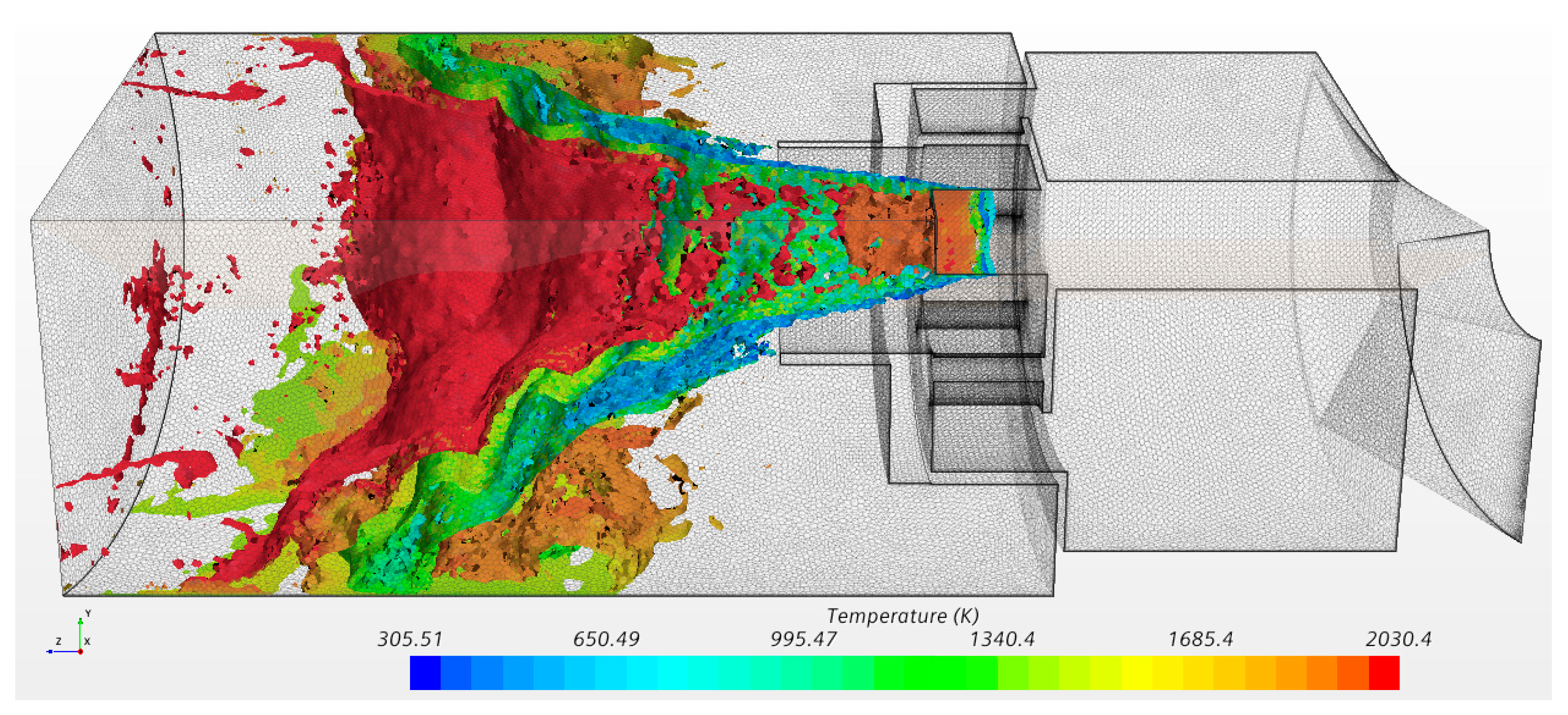
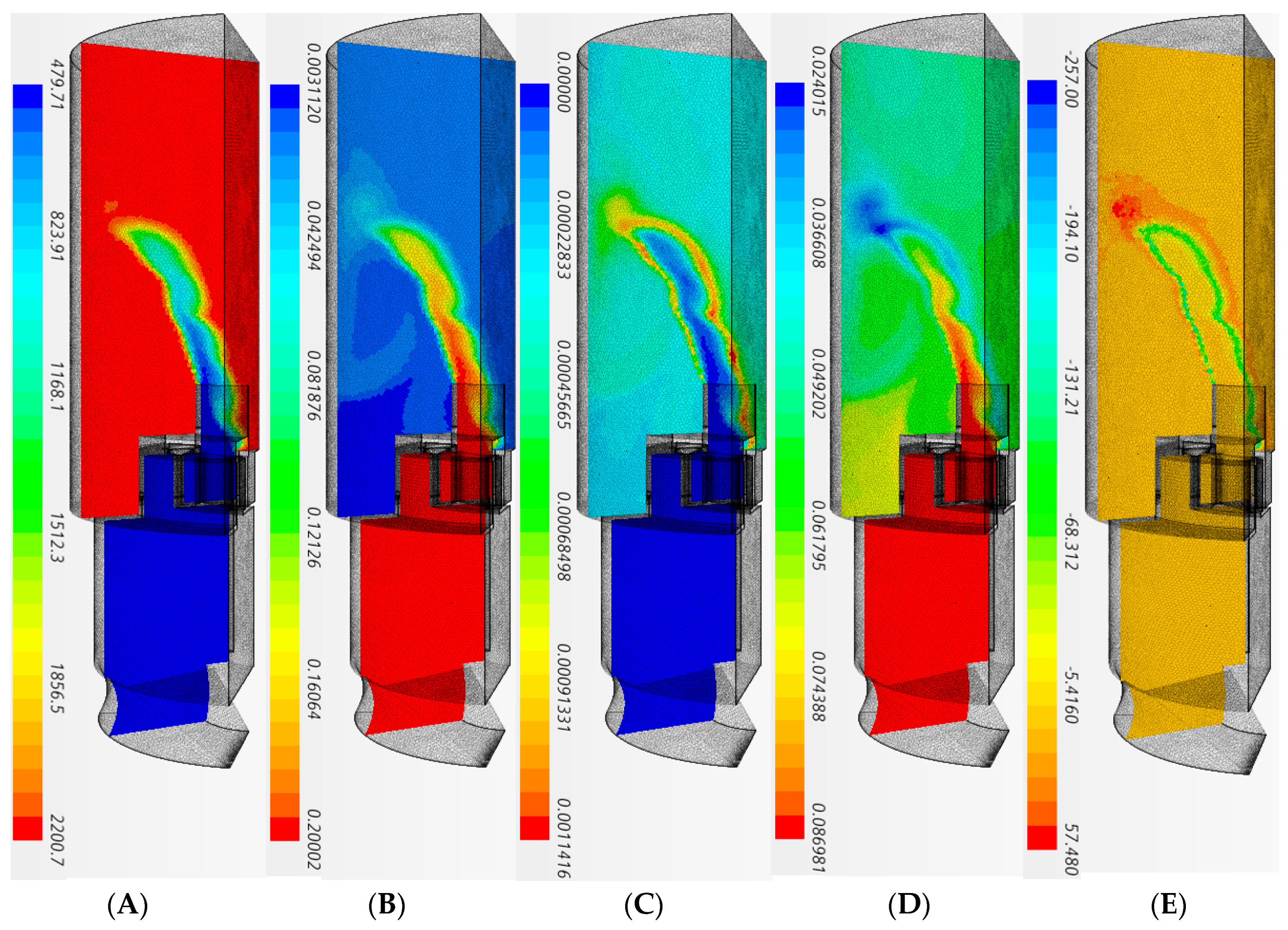
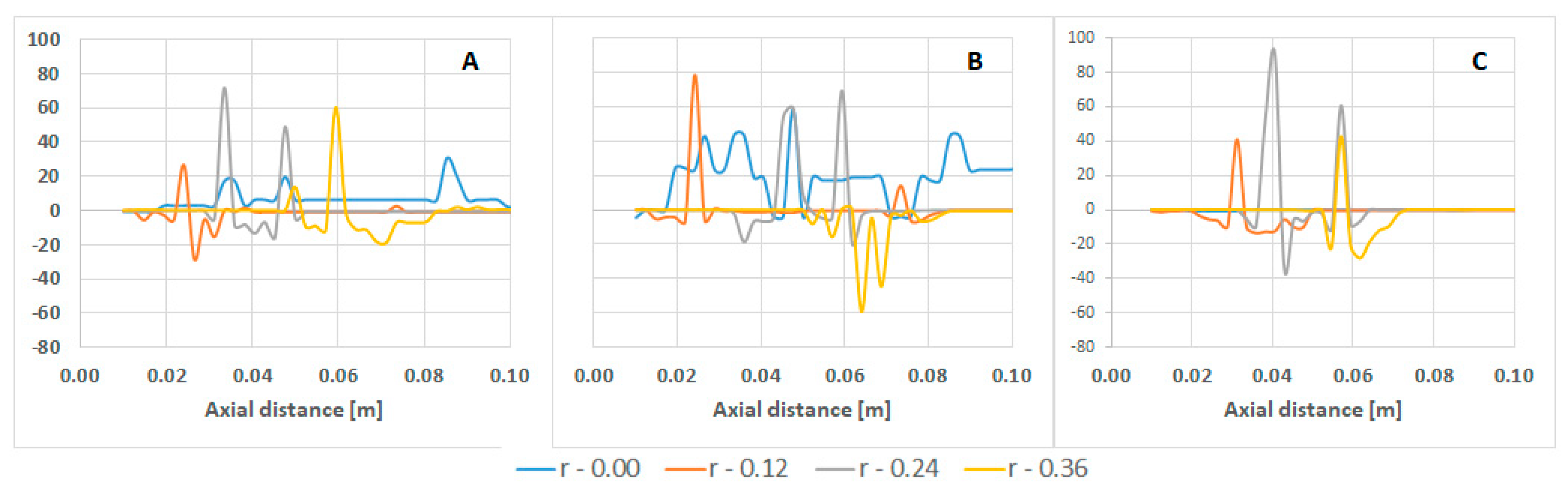
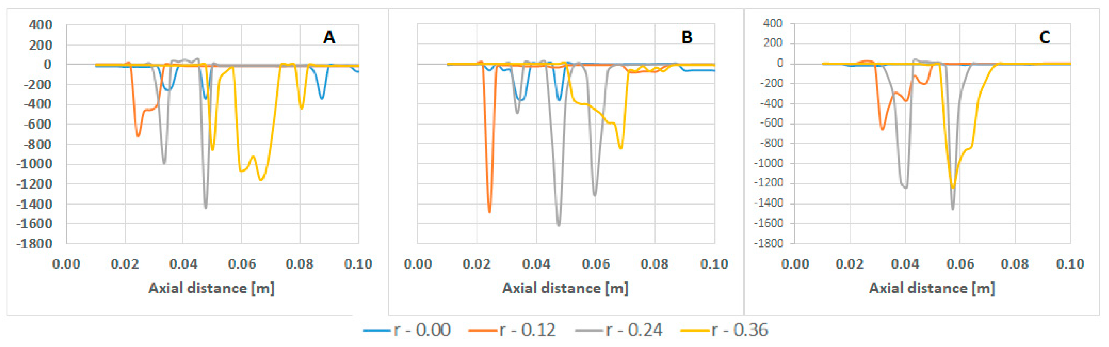
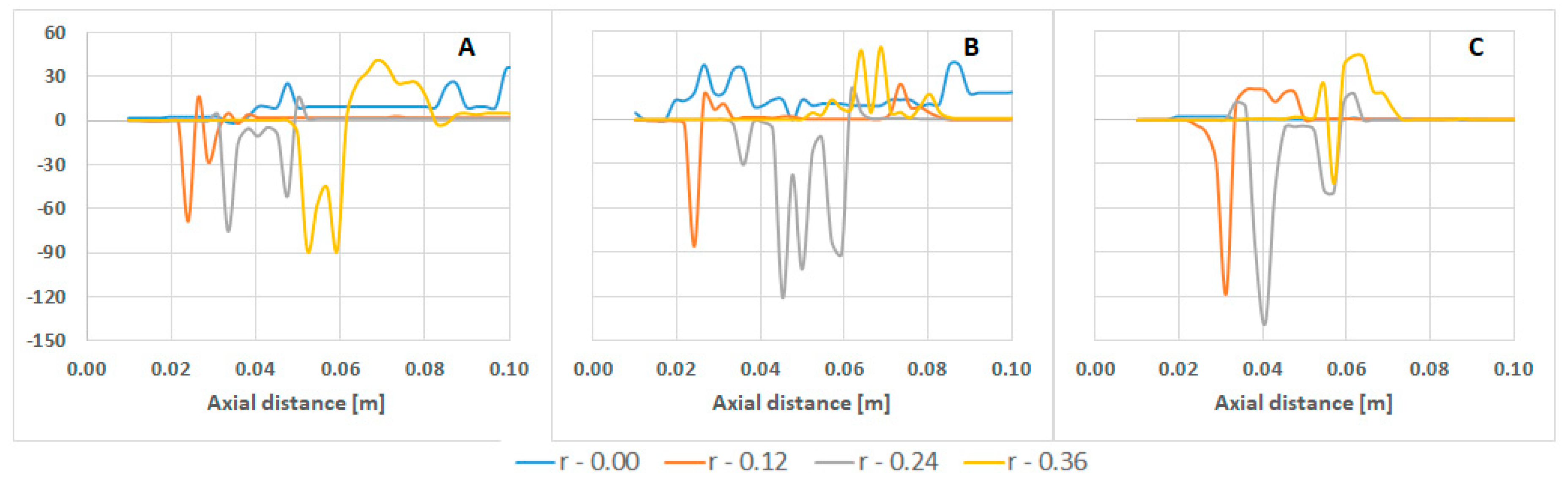
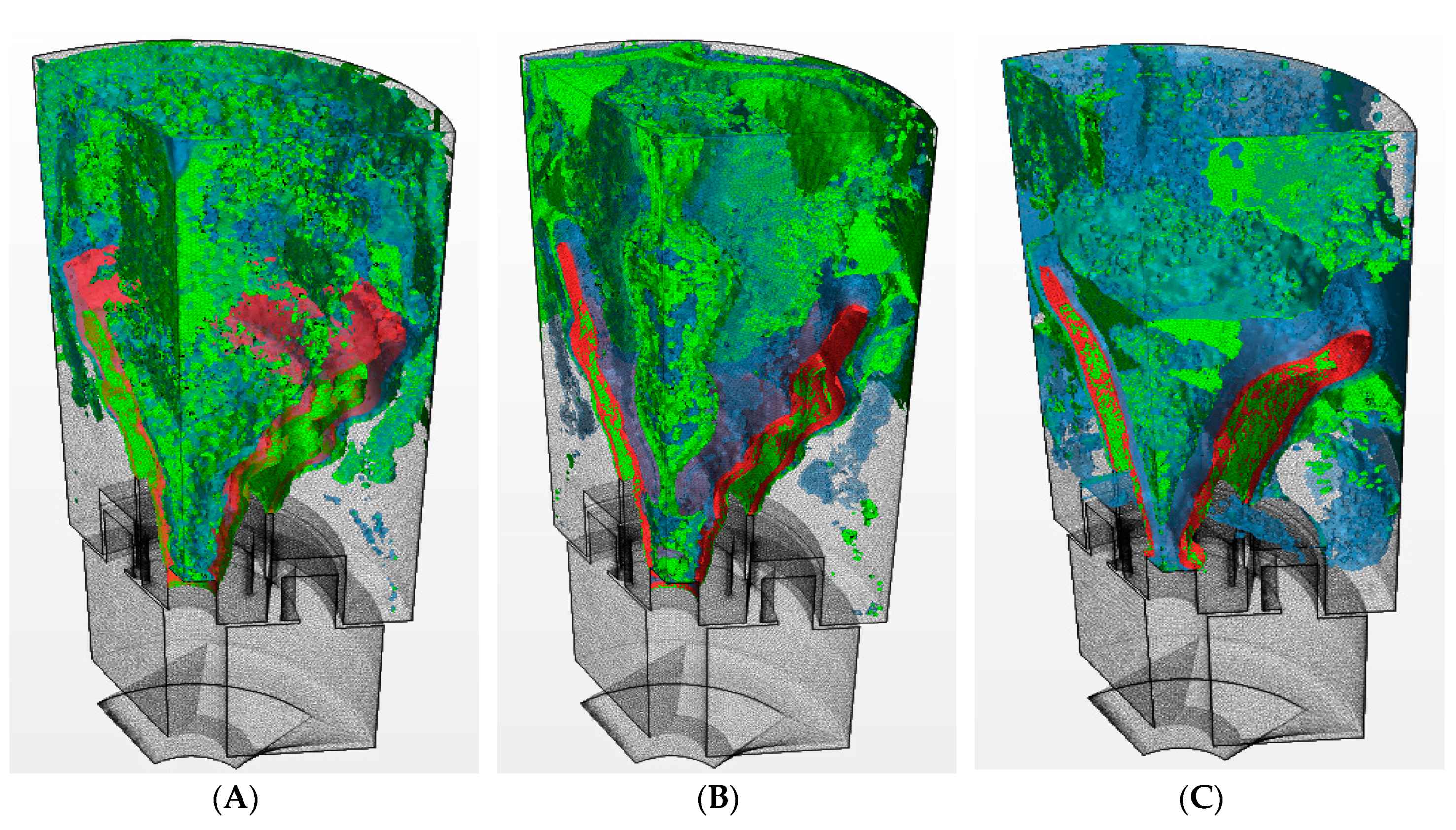
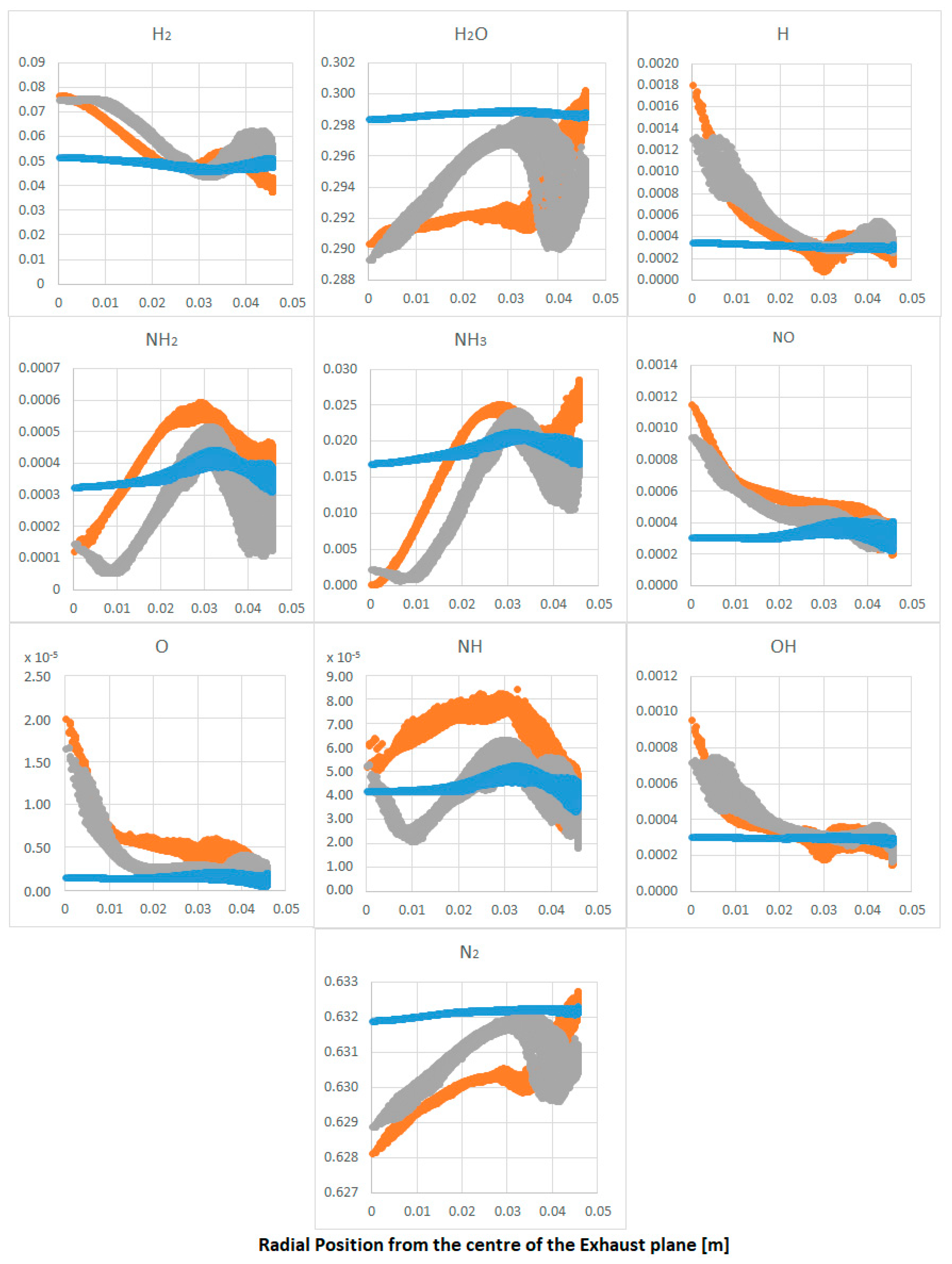
A numerical study was conducted to determine the exhaust gases obtained from the combustion of a 70–30 (mol%) ammonia–hydrogen blend under rich conditions (equivalence ratio of 1.2) and medium swirl (0.8), thus providing details for further thermodynamic analyses of a combustor previously evaluated using these settings [34,39]. Validation of the model was performed using the results from Valera-Medina et al. [39] and Pugh et al. [34]. Correlations were established between experimental and numerical concentrations of NOx, NH3, and H2 emissions. Temperatures at the base plate of the burner were also used. It is emphasized that no further temperature measurements were available due to corrosion problems experienced in the thermocouples of the high-pressure optical combustor (HPOC) section used for the experiments, a consequence of the high ammonia concentration (i.e., well-known to impact material integrity [45]).
The software Star-CCM+ v19.3 was employed. The analysis was conducted using RANS k-w SST modelling that is known to provide good average results for tangential swirling flows [46,47]. For the resolution of combustion, complex chemistry was employed by using a reduced kinetics mechanism developed by Okafor et al. [27]. The model was resolved using clustering to accelerate the chemistry resolution. Clustering reduces the computational expense of complex chemistry calculations by averaging cells with similar chemical compositions, integrating the reduced differential equations, and then interpolating the clusters back to the cells [48]. For turbulence-chemistry resolution, the laminar flame concept (LFC) was employed for this work, as the concept evaluates the instantaneous reaction rate at the mean temperature, pressure, and species mass fraction. Different to the Eddy dissipation concept (EDC), which integrates chemistry for a time scale close to Kolmogorov’s timescale, thus delivering slower reaction rates, LFC integrates the chemistry with respect to the residence time in the cell. The selection was based on results from previous campaigns and findings that denoted the high reactivity of this ammonia–hydrogen blend, with high NH2, OH, and H/O pools close to the flame front that increase the reactivity of the former [34,39]. Finally, the LFC model is appropriate for premixed, partially premixed, and unsteady flames [48]. The general species transport equation (Equation (1)) is then resolved,
t ρ Y i + x j ( ρ u j Y i + F k , j ) = ρ f ( Y i Y i τ )
where Yi is the species mass fraction, ρ is density, Fk,j the diffusion flux components, uj the velocity, f the mean reaction rate multiplier, and Yi* is the mass fraction at the end of a time integration τ (42).
In order to account for non-adiabatic conditions in the system (i.e., which are known to produce higher NOx and lower NH3 consequence of higher reactivity [44]), tests were conducted in a high-pressure optical combustor (HPOC) and validated with results [49] carried out in previous campaigns. A wall temperature of 1450 K was employed. A numerical mesh consisting of ~1.5 million cells was used for the calculations (Figure 1). The mesh represents only one-third of the entire section of the burner. Periodicity was established in all the side frontiers of the mesh in order to simulate the entire flow. The mesh was improved using local mesh refinement in the inner flame region downstream of the nozzle, Figure 2. Preliminary characterization was conducted for a mesh independency analysis. Meshes with ~800,000, ~1.5 million, and ~3.1 million cells were compared, with the intermediate cell providing similar results to the finest case. Residual values ranged from 10−4 to 10−6. The boundary conditions for the initial validation are specified in Table 1.
Once validation was accomplished, the model was extrapolated to high pressure and high inlet temperatures representative of larger power generation systems (Table 2). The selected conditions were estimated from the maximum capabilities of the HPOC system owned by Cardiff University, which can stably operate up to 9 bar and power outputs of ~200 kW. Although it is recognized that heat losses and thermal boundary conditions in the system are non-linear functions of pressure, flow rates, reactivity of species, and heat transfer from the combustion process and exhaust gases, and these are unknown for the extrapolated conditions, it is also highlighted that the estimates are solely a preliminary analysis of the use of ammonia–hydrogen blends at high operating conditions. Therefore, three different scenarios are presented in these analyses, namely (1) using the same wall temperature as in the validated case, (2) adiabatic conditions, and (3) an intermediate temperature between both points (Table 2).
Thermal power of the system was set at 196 kW. The blend’s specific energy was 48.6 MJ/kg. The fuel temperature at the inlet and air were both set at 500 K, with an ideal gas behavior. Inlet pressure of 0.90 MPa with an outlet pressure of 0.88 MPa (2% pressure drop) were considered (Table 2).

3. Results

Initial results were conducted to validate the CFD model against previous experimental data [34,39,50]. The results in Figure 3 and Figure 4 show good correlations. In terms of emissions, ammonia emissions are in good agreement with previous experimental campaigns (250 ppm versus 200 ppm). However, hydrogen is greater than predicted by the CFD study (3000 ppm experimentally against 5500 numerically). Simultaneously, NO emissions are over-predicted almost fourfold (293 ppm numerical and 70 ppm experimental). Although the ammonia has been well predicted, the consumption of hydrogen and its reaction close to the flame need to be further assessed by reaction mechanism developers.
Regarding the hydrodynamics of the flow, simulations and experiments were evaluated using isothermal conditions (since there is no experimental characterization of the hydrodynamics of ammonia/hydrogen flames yet). The experiments were determined using particle image velocimetry with the HPOC system. The comparison (Figure 4) shows the same trends, velocity profiles, and magnitude of coherent structures (i.e., central recirculation zone CRZ and shearing flow) between experiments and numerical analyses. It is believed that the discrepancy in the length of the shearing flow is caused by the reduced field of view, making it difficult for the post-processing software to fully resolve this region.
From the simulations (Figure 4), the appearance of an external recirculation zone attached to the quartz tube is clear. This recirculation, which is caused by the expansion of the flow and vorticity caused by the baroclinic differences in such a region, plays an important role in the final shape of the flame, which is addressed later. However, for the purpose of validation, there was confidence in the numerical approach to progress towards more extreme conditions.
The model in Figure 5 shows that it is under high temperatures >1700 K that unburned ammonia is decomposed into hydrogen after the flame. Also, NO is heavily found close to the flame front, as expected, with a decreasing concentration immediately after the breaking down point of unburned ammonia, a consequence of deNoxing effects caused by the interaction with NH2 produced from NH3 in the presence of OH. Recirculation patterns next to the wall (as seen in Figure 4) create higher concentration areas of NO emissions after the flame, but further formation of NO is limited in this region. Interestingly, NO reduction occurs at various temperatures above 700 K behind the flame in locations where external recirculation zones exist (Figure 6) and locations where unburned ammonia is also present, thus confirming the previous assertion.
However, the highly concentrated hydrogen post-flame barely reacted (Figure 5D), a consequence of the lack of oxygen and under-predictions in the reaction rates under these conditions. Traces of other radicals such as OH and water would increase the reactivity of hydrogen in the region, point observed by others [39]. This problem, previously observed in other works, is currently under research and is left aside for further analyses. However, the results are in the same order of magnitude to those obtained experimentally, thus enabling the analysis to move forward to semi-industrial conditions.
Figure 7, Figure 8 and Figure 9 show the emission profiles of this burner using ammonia/hydrogen at high pressures and high inlet temperatures with greater power outputs (Table 2). The results denote a considerable increase of hydrogen concentration compared to the atmospheric case. It is clear from the results that the production of hydrogen has increased in two orders of magnitude in the post-flame region. Moreover, although all cases show higher temperature profiles above 150 K, ammonia heavily appears in the post-flame region at concentrations >40,000 ppm, a problem observed with this burner configuration during previous experimental campaigns [39]. The increase of pressure seems to decrease the flame thickness, thus minimizing the reaction of the ammonia and hydrogen molecules, thus causing their high concentration at the core of the system and the outlet of the combustor. Surprisingly, NO still remains under similar values to those experimentally validated, i.e., 400–500 ppm. Although reduction of the molecule’s concentration was expected due to the lower combustion efficiency and increased concentration of ammonia (thus deNoxing effects), the higher inlet temperature has also increased reactivity, thus also the production of nitrogen oxide emissions [39]. Therefore, trends are as expected from all these results. Moreover, it is clear that flame profiles have changed. This is a consequence of an enhanced recirculation zone close to the wall (Figure 4), which increases in size and strength with temperature. This effect will impact on the final production/consumption of species. It is also known that the central recirculation zone will suffer at higher temperatures [43], thus reducing the swirl number in such a region. This will bring impacts towards the recirculation of species and further flame changes that will also account for the change in species reactivity.
It is remarkable to observe the progression of various intermediate molecules such as hydrogen, ammonia, and nitrogen oxides, which as previously stated, show variations at the analyzed conditions. Initial results were conducted to observe these progressions at different radius along the axial direction (Figure 10, Figure 11 and Figure 12).
Before assessing the results, it is important to emphasize that under adiabatic conditions, the reactions mainly occur through the flame or just a few centimeters above it, with all the reactions completed at the center line of the burner (radius r = 0.00). Therefore, there is no production/consumption rates at this radius under adiabatic conditions. Nevertheless, it is assumed that the trends from low to high temperature are maintained, as explained below. Also, the intermediate radius r = 0.24 crosses from bottom to top the flame. This fact needs to be emphasized to recognize the impacts caused by the flame between cases.
In terms of NO production/consumption (Figure 10), it is evident how the raise in confinement temperature has increased the production of the molecule along most radiuses, especially at the centerline and through the flame (r = 0.24). However, it is also clear that the rate of consumption has also increased closer to the wall at higher temperatures. Both phenomena are linked to the higher temperature of the flame and the no-slip condition close to the wall that creates structures that increase the residence time of NO and unburned ammonia, respectively. This interaction, evident in Figure 11, shows that close to the wall (r = 0.36), ammonia is highly consumed in all cases. The consumption of NH3 through the flame remains almost constant, while the overall consumption increases with temperature. However, it is also interesting to see some peaks of NO at the same locations where ammonia is being consumed close to the flame. The phenomenon could be a consequence of an increase in O radicals (via the increase of OH) promoting NO by enhancing the oxidation of NH2 to NHO and NH to NO.
Hydrogen has also changed its pattern considerably. Different to ammonia, hydrogen seems to have a high decrease across the flame at higher confinement temperatures. However, it is also evident that the overall production of the molecule has increased further down the axial direction. This hydrogen is believed to be produced by the decomposition of ammonia into NHx radicals and H molecules, as is evident from the decrease of ammonia in the locations where hydrogen is produced. Therefore, ammonia seems to be acting as a reductant of NO close to the wall, a producer of NO closer to the flame, and a hydrogen enabler downstream the combustion zone.
Figure 13 provides more evidence of this trend. Results show that some hydrogen production comes mainly from the destruction of the surrounding ammonia in the post-flame zone at temperatures ~2050 K. However, according to the high levels of hydrogen in the final flue gas (Figure 14), it seems as if hydrogen does not have enough time to fully react through the flame front under these conditions. This is a problem related to the thinner flame front at these higher pressures combined with the high hydrogen content of the initial blend. Nevertheless, as overall temperatures of the confinement increase due to lower heat losses (i.e., hotter boundary conditions), the production of hydrogen and destruction of ammonia considerably increases across the field, i.e., compare Figure 13A–C. Not surprisingly, hydrogen production at the outlet has also increased with a reduction of ammonia concentration in the flue gases as temperatures raise across the combustor. Moreover, water and nitrogen have increased with a reduction of NHx species at higher temperatures, Figure 14.
Hydrogen radicals H and hydroxyls OH remain constant at the end of the burner. Thus, the higher field temperatures and post-flame recombination led to a negative impact on the concentration of NHx species whilst delivering cleaner flue exhaust gases (i.e., higher water, hydrogen, and nitrogen contents).
From the still high concentrations of unreacted ammonia just after the flame to the exit of the system, NH3 emissions at the outlet have plummeted two-fold (~20,000 ppm), with NOx still well under 1000 ppm (with an average value of only 330–390 ppm) for all cases. Not surprisingly, adiabatic conditions have produced the most consistent results with higher water and nitrogen in the product gases, whilst intermediate molecules (i.e., H, O, OH, NH, NH2) have been further reduced. Hydrogen and ammonia, in general terms, have remained at similar values to their non-adiabatic counterparts, thus showing that the higher temperatures will impact directly on unreacted radicals to form water and nitrogen species rather than impacting on the former in location far from the flame and walls. This statement, although somehow demonstrated at much lower pressures by previous experiments, should be carefully approached as a consequence of the still unresolved hydrogen reaction via the employed reaction mechanism, as previously highlighted.
However, if accurate, the high concentration of hydrogen (average 5.5%) with ammonia (average 1.5%) and amidogen (NH2, average 286 ppm) could be employed for secondary stage combustion, minimizing even further the NHx traces. Highly humidified conditions also present in the system (i.e., 30% steam) could also support the production of extra power, increasing overall combustion efficiencies whilst delivering steam for other processes. It is emphasized that further experimental validations will be performed in a posterior project for these semi-industrial operational conditions.

4. Conclusions

The present work has been conducted to assess the potential effects of high pressure, high inlet temperatures, and higher power outputs for gas turbine systems fueled with ammonia/hydrogen blends. The results were first validated using experimental conditions, whilst extrapolated, more industrially relevant conditions were assessed using different heat losses through the boundary conditions of the system. The results showed that:
  • The reaction model has a good prediction for the consumption/production of ammonia under atmospheric conditions. However, hydrogen reactivity is still not fully solved, with nitrogen oxides also being over-estimated.
  • Nitrogen oxides remain at similar levels in most calculations, a consequence of a combined effect between the higher reactivity of the reactants at higher confinement temperatures and the increased reactivity of NO with unburned ammonia along the wall.
  • Higher temperatures across the post-flame region (e.g., reduced heat losses through the boundary condition) show an increase in reactivity of ammonia for the formation of hydrogen. Ammonia, whose reactivity remains relatively the same at different conditions across the flame, also produces nitrogen oxides (probably as a result of the production of NHO and NH).
  • On the other hand, hydrogen consumption through the flame is dependent on confinement temperatures, with an increase of the molecule caused by the decomposition of ammonia downstream the flame.
  • Larger quantities of water and nitrogen are produced at higher temperatures through the complete reaction of intermediate molecules. Hydrogen and ammonia remain at the same concentrations at the exhaust. Therefore, the energy provided by the change in confinement temperature will have a direct impact on hydrogen through the flame and radical formation post-combustion.

Author Contributions

Formal analysis, M.-E.T.-d.-C.; investigation, J.-A.V.-S.; methodology, A.-L.H.-M.; supervision, A.V.-M.; writing—original draft, M.-O.V.-Z. All authors have read and agreed to the published version of the manuscript.

Funding

This research was partially funded by FLEXIS [project no. 80835].

Acknowledgments

The authors gratefully acknowledge the support from CONACYT, Cardiff University and Universidad Veracruzana to be interested in this research field. Valera-Medina gratefully acknowledges the support from the project FLEXIS provided by a joint venture between the Welsh Government and the European Union.

Conflicts of Interest

The authors declare no conflict of interest. Also, The funders had no role in the design of the study; in the collection, analyses, or interpretation of data; in the writing of the manuscript, or in the decision to publish the results.

References

  1. Birol, F. Hydrogen: Accelerating & Expanding Deployment. Available online: https://www.nedo.go.jp/content/100885441.pdf (accessed on 10 September 2019).
  2. YARA. YARA Fertilizer Industry Handbook; Yara: Oslo, Norway, 2018. [Google Scholar]
  3. Porter, D.H. The Life and Times of Sir Goldsworthy Gurney: Gentleman Scientist and Inventor, 1793-1875; Lehigh University Press: Bethlehem, PA, USA, 1998. [Google Scholar]
  4. Krock, E. Ammonia—A Fuel for Motor Busses. J. Inst. Pet. 1945, 31, 213–223. [Google Scholar]
  5. Verkamp, F.J.; Hardin, M.C.; Williams, J.R. Ammonia Combustion Properties and Performance in Gas-Turbine Burners. In Symposium (International) on Combustion; Elsevier: Amsterdam, The Netherlands, 1967; Volume 11, pp. 985–992. [Google Scholar]
  6. Pratt, D.T. Performance of Ammonia-Fired Gas-Turbine Combustors; DTIC Document, University of California: Los Angeles, CA, USA, 1967. [Google Scholar]
  7. HI Solar. Development of an Ammonia-Burning Gas Turbine Engine. 1966. Available online: https://apps.dtic.mil/dtic/tr/fulltext/u2/6716 (accessed on 19 October 2019).
  8. Kailos, N.C. Utilization of Ammonia as an Alternative Fuel in Army Aircraft Engines: USAAVLABS Technical Report 66-52; U.S. Army, USA, 1966. Available online: https://apps.dtic.mil/dtic/tr/fulltext/u2/638360.pdf.chemical (accessed on 5 January 2020).
  9. Fenimore, C.P.; Jones, G.W. Oxidation of Ammonia in Flames. J. Phys. Chem. 1961, 65, 298–303. [Google Scholar] [CrossRef]
  10. Maclean, D.I.; Wagner, H.G. The Structure of the Reaction Zones of Ammonia-Oxygen and Hydrazine-Decomposition Flames. Symp. Combust. 1967, 11, 871–878. [Google Scholar] [CrossRef]
  11. Miller, J.A.; Bowman, C.T. Mechanism and Modeling of Nitrogen Chemistry in Combustion. Prog. Energy Combust. Sci. 1989, 15, 287–338. [Google Scholar] [CrossRef]
  12. Lindstedt, R.; Lockwood, F.C.; Selim, M.A. Detailed Kinetic Modelling of Chemistry and Temperature Effects on Ammonia Oxidation. Combust. Sci. Technol. 1994, 99, 253–276. [Google Scholar] [CrossRef]
  13. Skreiberg, Ø.; Kilpinen, P.; Glarborg, P. Ammonia Chemistry below 1400 K under Fuel-Rich Conditions in a Flow Reactor. Combust. Flame 2004, 136, 501–518. [Google Scholar] [CrossRef]
  14. Duynslaegher, C.; Jeanmart, H.; Vandooren, J. Ammonia Combustion at Elevated Pressure and Temperature Conditions. Fuel 2010, 89, 3540–3545. [Google Scholar] [CrossRef]
  15. Konnov, A.A. Detailed Reaction Mechanism for Small Hydrocarbons Combustion. Release 0.5 2000; Lund University: Lund, Sweden, 2000. [Google Scholar]
  16. Tian, Z.; Li, Y.; Zhang, L.; Glarborg, P.; Qi, F. An Experimental and Kinetic Modeling Study of Premixed NH3/CH4/O2/Ar Flames at Low Pressure. Combust. Flame 2009, 156, 1413–1426. [Google Scholar] [CrossRef]
  17. Mendiara, T.; Glarborg, P. Ammonia Chemistry in Oxy-Fuel Combustion of Methane. Combust. Flame 2009, 156, 1937–1949. [Google Scholar] [CrossRef]
  18. Klippenstein, S.J.; Harding, L.B.; Glarborg, P.; Miller, J.A. The Role of NNH in NO Formation and Control. Combust. Flame 2011, 158, 774–789. [Google Scholar] [CrossRef] [Green Version]
  19. Xiao, H.; Valera-Medina, A. Chemical Kinetic Mechanism Study on Premixed Combustion of Ammonia/Hydrogen Fuels for Gas Turbine Use. J. Eng. Gas Turbines Power 2017, 139. [Google Scholar] [CrossRef]
  20. Xiao, H.; Valera-Medina, A.; Bowen, P.J. Modeling Combustion of Ammonia/Hydrogen Fuel Blends under Gas Turbine Conditions. Energy Fuels 2017, 31, 8631–8642. [Google Scholar] [CrossRef]
  21. Mathieu, O.; Petersen, E.L. Experimental and Modeling Study on the High-Temperature Oxidation of Ammonia and Related NOx Chemistry. Combust. Flame 2015, 162, 554–570. [Google Scholar] [CrossRef] [Green Version]
  22. Guteša Božo, M.; Valera-Medina, A.; Syred, N.; Bowen, P.J. Fuel quality impact analysis for practical implementation of corn cob gasification gas in conventional gas turbine power plants. Biomass Bioenergy 2019, 122, 221–230. [Google Scholar]
  23. Guteša Božo, M.; Vigueras-Zuniga, M.; Buffi, M.; Seljak, T.; Valera-Medina, A. Fuel Rich Ammonia-Hydrogen Injection for Humidified Gas Turbines. Appl. Energy 2019, 251, 113334. [Google Scholar] [CrossRef]
  24. Gutesa-Bozo, M.; Valera-Medina, A. Novel Humidified Ammonia/Hydrogen Gas Turbine Cycles. SMARTCATS Conference. COST Action, EU. 2019. Available online: https://www.smartcats.eu/ (accessed on 5 January 2020).
  25. Glarborg, P.; Miller, J.A.; Ruscic, B.; Klippenstein, S.J. Modeling Nitrogen Chemistry in Combustion. Prog. Energy Combust. Sci. 2018, 67, 31–68. [Google Scholar] [CrossRef] [Green Version]
  26. Da Rocha, R.C.; Costa, M.; Bai, X.-S. Chemical Kinetic Modelling of Ammonia/Hydrogen/Air Ignition, Premixed Flame Propagation and NO Emission. Fuel 2019, 246, 24–33. [Google Scholar] [CrossRef]
  27. Okafor, E.C.; Naito, Y.; Colson, S.; Ichikawa, A.; Kudo, T.; Hayakawa, A.; Kobayashi, H. Experimental and Numerical Study of the Laminar Burning Velocity of CH4–NH3–Air Premixed Flames. Combust. Flame 2018, 187, 185–198. [Google Scholar] [CrossRef]
  28. GRI-Mech, V. 3.0. Gas Research Institute, GRI-Mech, Ver. 3.0. Available online: http://www.Me.Berkely.Edu/Gri-Mech/ (accessed on 19 June 2018).
  29. Arif, K.; Brian, E. Fuel Conditioning System for Ammonia Fired Power Plants, NH3 Fuel Association, October 2012. Available online: Https://Nh3fuel.Files.Wordpress.Com/2012/10/Evans-Brian.Pdf (accessed on 21 November 2016).
  30. Kobayashi, H.; Hayakawa, A.; Somarathne, K.D.K.A.; Okafor, E.C. Science and Technology of Ammonia Combustion. Proc. Combust. Inst. 2019, 37, 109–133. [Google Scholar] [CrossRef]
  31. Okafor, E.C.; Somarathne, K.D.K.A.; Hayakawa, A.; Kudo, T.; Kurata, O.; Iki, N.; Kobayashi, H. Towards the Development of an Efficient Low-NOx Ammonia Combustor for a Micro Gas Turbine. Proc. Combust. Inst. 2019, 37, 4597–4606. [Google Scholar] [CrossRef]
  32. Valera-Medina, A.; Xiao, H.; Owen-Jones, M.; David, W.I.F.; Bowen, P.J. Ammonia for Power. Prog. Energy Combust. Sci. 2018, 69, 63–102. [Google Scholar] [CrossRef]
  33. Hewlett, S.G.; Valera-Medina, A.; Pugh, D.G.; Bowen, P.J. Gas Turbine Co-Firing of Steelworks Ammonia with Coke Oven Gas: A Fundamental and Cycle Analysis. In Proceedings of the ASME Turbo Expo, Phoenix, AZ, USA, 17–21 June 2019; p. GT2019-91404. [Google Scholar]
  34. Pugh, D.; Bowen, P.; Valera-Medina, A.; Giles, A.; Runyon, J.; Marsh, R. Influence of Steam Addition and Elevated Ambient Conditions on NOx Reduction in a Staged Premixed Swirling NH3/H2 Flame. Proc. Combust. Inst. 2019, 37, 5401–5409. [Google Scholar] [CrossRef]
  35. Okafor, E.C.; Somarathne, K.D.K.A.; Ratthanan, R.; Hayakawa, A.; Kudo, T.; Kurata, O.; Iki, N.; Tsujimura, T.; Furutani, H.; Kobayashi, H. Control of NOx and Other Emissions in Micro Gas Turbine Combustors Fuelled with Mixtures of Methane and Ammonia. Combust. Flame 2020, 211, 406–416. [Google Scholar] [CrossRef]
  36. Ito, S.; Uchida, M.; Onishi, S.; Fujimor, T.; Kobayashi, T. Performance of Ammonia–Natural Gas Co-fired Gas Turbine for Power Generation. Available online: https://nh3fuelassociation.org/wp-content/uploads/2018/12/1545-Performance-of-Ammonia–Natural-Gas-for-Power-Generation-for-Power-Generation.pdf (accessed on 24 June 2019).
  37. Yamagami, A.; Fujiwara, H. World’s First Successful Ammonia Synthesis Using Renewable Energy-Based Hydrogen and Power Generation. Available online: https://ammoniaindustry.com/jgc-corporation-demonstrates-worlds-first-carbon-free-ammonia-energy-cycle/ (accessed on 2 June 2019).
  38. Goldmann, A.; Sauter, W.; Oettinger, M.; Kluge, T.; Schröder, U.; Seume, J.; Friedrichs, J.; Dinkelacker, F. A Study on Electrofuels in Aviation. Energies 2018, 11, 392. [Google Scholar] [CrossRef] [Green Version]
  39. Valera-Medina, A.; Gutesa, M.; Xiao, H.; Pugh, D.; Giles, A.; Goktepe, B.; Marsh, R.; Bowen, P. Premixed Ammonia/Hydrogen Swirl Combustion under Rich Fuel Conditions for Gas Turbines Operation. Int. J. Hydrogen Energy 2019, 44, 8615–8626. [Google Scholar] [CrossRef]
  40. Zhao, D.; Guan, Y.; Reinecke, A. Characterizing Hydrogen-Fuelled Pulsating Combustion on Thermodynamic Properties of a Combustor. Commun. Phys. 2019, 2, 44. [Google Scholar] [CrossRef] [Green Version]
  41. Terhaar, S.; Krüger, O.; Paschereit, C.O. Flow Field and Flame Dynamics of Swirling Methane and Hydrogen Flames at Dry and Steam Diluted Conditions. J. Eng. Gas Turbines Power 2015, 137. [Google Scholar] [CrossRef]
  42. Syred, N.; Giles, A.; Lewis, J.; Abdulsada, M.; Valera Medina, A.; Marsh, R.; Bowen, P.J.; Griffiths, A.J. Effect of Inlet and Outlet Configurations on Blow-off and Flashback with Premixed Combustion for Methane and a High Hydrogen Content Fuel in a Generic Swirl Burner. Appl. Energy 2014, 116. [Google Scholar] [CrossRef]
  43. Syred, N.; Abdulsada, M.; Griffiths, A.; O’Doherty, T.; Bowen, P. The Effect of Hydrogen Containing Fuel Blends upon Flashback in Swirl Burners. Appl. Energy 2012, 89, 106–110. [Google Scholar] [CrossRef] [Green Version]
  44. Honzawa, T.; Kai, R.; Okada, A.; Valera-Medina, A.; Bowen, P.J.; Kurose, R. Predictions of NO and CO Emissions in Ammonia/Methane/Air Combustion by LES Using a Non-Adiabatic Flamelet Generated Manifold. Energy 2019, 186, 115771. [Google Scholar] [CrossRef]
  45. Monteiro-Davalos, R. Observations of Corrosion Product Formation and Stress Corrosion Cracking on Brass Samples Exposed to Ammonia Environments. Mater. Res. 2018, 22, e20180077. [Google Scholar] [CrossRef] [Green Version]
  46. Valera-Medina, A.; Vigueras-Zuniga, M.O.; Baej, H.; Syred, N.; Chong, C.T.; Bowen, P.J. Outlet Geometrical Impacts on Blowoff Effects When Using Various Syngas Mixtures in Swirling Flows. Appl. Energy 2017, 207. [Google Scholar] [CrossRef]
  47. Baej, H.; Valera-Medina, A.; Bowen, P.; Syred, N.; O’Doherty, T.; Marsh, R. Impacts on Blowoff by a Variety of CRZs Using Various Gases for Gas Turbines. Energy Procedia 2014, 61, 1606–1609. [Google Scholar] [CrossRef] [Green Version]
  48. Siemens. Complex Chemistry. Available online: https://documentation.thesteveportal.plm.automation.siemens.coml (accessed on 24 September 2019).
  49. Valera-Medina, A.; Giles, A.; Pugh, D.; Morris, S.; Pohl, M.; Ortwein, A. Investigation of Combustion of Emulated Biogas in a Gas Turbine Test Rig. J. Therm. Sci. 2018, 27, 331–340. [Google Scholar] [CrossRef]
  50. Runyon, J.; Marsh, R.; Bowen, P.; Pugh, D.; Giles, A.; Morris, S. Lean Methane Flame Stability in a Premixed Generic Swirl Burner: Isothermal Flow and Atmospheric Combustion Characterization. Exp. Therm. Fluid Sci. 2018, 92, 125–140. [Google Scholar] [CrossRef]
Figure 1. Experimental rig (a) instrumentation and pilot injection lance, (b) inlet plenum, (c) mixing plenum, (d) radial-tangential swirler insert, (e) exit nozzle, (f) quartz window, (g) quartz confinement, and (h) high-pressure optical combustor (HPOC) casing.
Energies 13 00288 g001
Figure 2. Mesh used for modelling. (Top) Full mesh; (Bottom left) Details of the swirl vanes; (Bottom right) Close-up of local mesh refinement.
Energies 13 00288 g002
Figure 3. Validation using exhaust emissions profiles. Experiments as in [34,39].
Energies 13 00288 g003
Figure 4. Isothermal results. (Left) Experiments from [50]; (right) numerical analysis (zone of interest highlighted). Velocity magnitudes (in the shearing flow and CRZ) and location of the coherent structures are extremely close between cases.
Energies 13 00288 g004
Figure 5. (A) Temperature (K); (B) ammonia concentration (mol%); (C) NO concentration (mol%); (D) hydrogen concentration (mol%); (E) hydrogen rate of production (kg/m3·s). Operating conditions: 101 kPa, 304 K.
Energies 13 00288 g005
Figure 6. Isosurface of NO reduction (−0.1 kg/m3·s) over-imposed on temperature profiles.
Energies 13 00288 g006
Figure 7. (A) Temperature (K); (B) ammonia concentration (mol%); (C) NO concentration (mol%); (D) hydrogen concentration (mol%); (E) hydrogen rate of production (kg/m3·s). Operating conditions: 900 kPa, 500 K inlet temperature, 1450 K quartz tube.
Energies 13 00288 g007
Figure 8. (A) Temperature (K); (B) ammonia concentration (mol%); (C) NO concentration (mol%); (D) hydrogen concentration (mol%); (E) hydrogen rate of production (kg/m3·s). Operating conditions: 900 kPa, 500 K inlet temperature, 1800 K quartz tube.
Energies 13 00288 g008
Figure 9. (A) Temperature (K); (B) ammonia concentration (mol%); (C) NO concentration (mol%); (D) hydrogen concentration (mol%); (E) hydrogen rate of production (kg/m3·s). Operating conditions: 900 kPa, 500 K inlet temperature, adiabatic quartz tube.
Energies 13 00288 g009
Figure 10. NO production at different radius (0.00, 0.12, 0.24, 0.36) (r) along the axis, (A) 1450 K; (B) 1800 K; (C) adiabatic. Units (kg/m3·s).
Energies 13 00288 g010
Figure 11. NH3 production at different radius (0.00, 0.12, 0.24, 0.36) (r) along the axis, (A) 1450 K; (B) 1800 K; (C) adiabatic. Units (kg/m3·s).
Energies 13 00288 g011
Figure 12. H2 production at different radius (0.00, 0.12, 0.24, 0.36) (r) along the axis, (A) 1450 K; (B) 1800 K; (C) adiabatic.
Energies 13 00288 g012
Figure 13. Isosurfaces (same opacities and thresholds) of the production of hydrogen (blue) through the destruction of ammonia (green) after the flame (red). Operating conditions: 900 kPa, 500 K. (A) 1450 K; (B) 1800 K; (C) adiabatic conditions.
Energies 13 00288 g013
Figure 14. Molar fraction (−) of different emissions at the outlet of the burner at different quartz temperatures—1450 K (orange), 1800 K (grey), adiabatic (blue).
Energies 13 00288 g014
Table 1. Boundary conditions; atmospheric conditions.
ParameterValueParameterValue
Quartz Temperature1450 KOkafor Mechanism130 Reactions
Inlet Velocity3 m/sMethodSegregated Flow
Inlet Temperature304 KIgnition Temperature3000 K
Pressure101,300 PaTurbulence10%
Outlet Pressure99,274 PaBurner sectionSymmetry (120°)
WallsNo-slipSwirler wallsAdiabatic
Table 2. Boundary conditions; high-pressure, high inlet temperature conditions.
ParameterValueParameterValue
Quartz Temperature1450, 1800, 2150 KOkafor Mechanism130 Reactions
Inlet Velocity20 m/sMethodSegregated Flow
Inlet Temperature500 KIgnition Temperature3000 K
Inlet Pressure0.90 MPaTurbulence10%
Outlet Pressure0.88 MPaBurner sectionSymmetry (120°)
WallsNo-slipSwirler wallsAdiabatic

