Article

Zero-Vector-Injection Based Current Sharing Control of Interleaved Full-Bridge LLC Resonant Converters

School of Automation, Northwestern Polytechnical University, 1 Dongxiang Road, Chang’an District, Xi’an 710129, China
*
Author to whom correspondence should be addressed.
Energies 2020, 13(2), 347; https://doi.org/10.3390/en13020347
Submission received: 20 December 2019 / Revised: 3 January 2020 / Accepted: 6 January 2020 / Published: 10 January 2020

Abstract

:
Interleaved LLC resonant converters are widely used in various fields. However, interleaved LLC converters under Pulse Frequency Modulation (PFM) will lose the regulation of individual phases, causing a load sharing problem. Existing load sharing solutions have limitations; for example, phase shedding and current sharing cannot be realized at the same time. This paper proposed a novel current sharing method for interleaved full-bridge LLC resonant converters. Based on Zero-Vector-Injection, the voltage applied to the resonant tank is controlled to compensate for the difference in gain caused by component tolerance. The modulation strategy is proposed to maintain soft switching after Zero-Vector-Injection, and the phase shedding technique is also used to improve the efficiency at a light load. The detailed theoretical analysis and implementation method are proposed and validated using simulations. Experiments are also carried out to verify the feasibility of the proposed strategy based on a 2-phase 1.8 kW prototype.

1. Introduction

Due to high efficiency, high power density and simple structure, etc., the LLC resonant converter is widely applied in electric vehicles, high-power microwave systems, aerospace power supplies, communication power supplies, Micro-Grid and UPS equipment [1,2,3,4,5,6,7,8,9,10,11,12]. To further improve the performance of the LLC resonant converter in high current applications, an interleaving technique is proposed [13,14,15,16], which has the advantages of lower conduction loss, smaller current ripple and phase shedding capability. Interleaved LLC converters are operating at the same switching frequency for ripple cancelation. However, the resonant frequencies of each LLC converter are always different due to component tolerance, which makes the gain of each phase different under the same switching frequency, which results in uneven current [17,18].
Since switching frequency cannot be adjusted individually, previous works tried to change the parameters or structure of the resonant tank to achieve current sharing. The Switch Controlled Capacitor (SCC) based current sharing method used a switch-controlled capacitor to adjust the gain of each LLC converter individually, which achieved very good performance [19,20]. However, the control system of this approach is very complicated, which not only increase cost but also decrease system reliability. A method based on variable-inductor is proposed, in which a controlled DC current source is needed to change the value of inductor [21]. Obviously, the drawbacks of variable-inductor based approach are the same as the SCC based approach. The common-inductor and common-capacitor-based approach are proposed in References [22,23,24], which can realize automatic current sharing. These kinds of methods are convenient and do not add extra hardware. However, the current sharing performance of these passive approaches is not as good as the active approach. Moreover, reliability is a very big issue, and phase shedding cannot be implemented. In References [25,26], diodes at the secondary side are replaced by MOSFET, which are used to change the gain of the converter. This method also brings additional hardware and control costs, and synchronous rectification cannot be realized. In Reference [27], a passive current sharing method is proposed by adding a balancing transformer to the LLC converter. This method does not require additional control loops, but its current sharing accuracy is not as high as active current sharing method. And when it is applied to the multi-phases LLC converter, the design of its balancing transformer will have certain difficulties, and will make the hardware of the parallel system more complicated. In References [28,29], by adding fly capacitors, this method can be extended to multi-phase applications with good current sharing performance. However, it is not able to implement phase-shedding technology, and the additional fly capacitors reduce the input voltage of each phase. This is an advantage for step-down LLC, but for step-up LLC, this method will lead to an increase in the transformer ratio and the primary current, which will affect efficiency.
Compared with passive methods, active current sharing methods have the advantages of high current sharing accuracy and strong controllability. Most active current sharing methods can realize phase-shedding technology to improve light-load efficiency, and they can achieve current sharing with almost no additional hardware or topology modification, which leads to higher reliability.
In a high power application with low input voltage and high step-up ratio, the full-bridge LLC resonant converter is widely adopted. For full-bridge topology, the voltage applied to the resonant tank can be adjusted by Zero-Vector-Injection, which is another control freedom.
In this paper, a new active current sharing approach for interleaved LLC resonant converters is proposed. The voltage applied to the resonant tank is adjusted by injecting zero vectors to compensate for the gain difference caused by component tolerance. In this approach, high-accuracy current sharing and phase shedding can be realized while retaining soft-switching capability. Moreover, the proposed approach does not add any extra component and does not change the circuit structure. Section 2 is the principle of Zero-Vector-Injection-based current sharing. Section 3 is the detailed implementation of Zero-Vector-Injection and soft switching. Section 4 gives simulation and experimental verification. Section 5 is the conclusion.

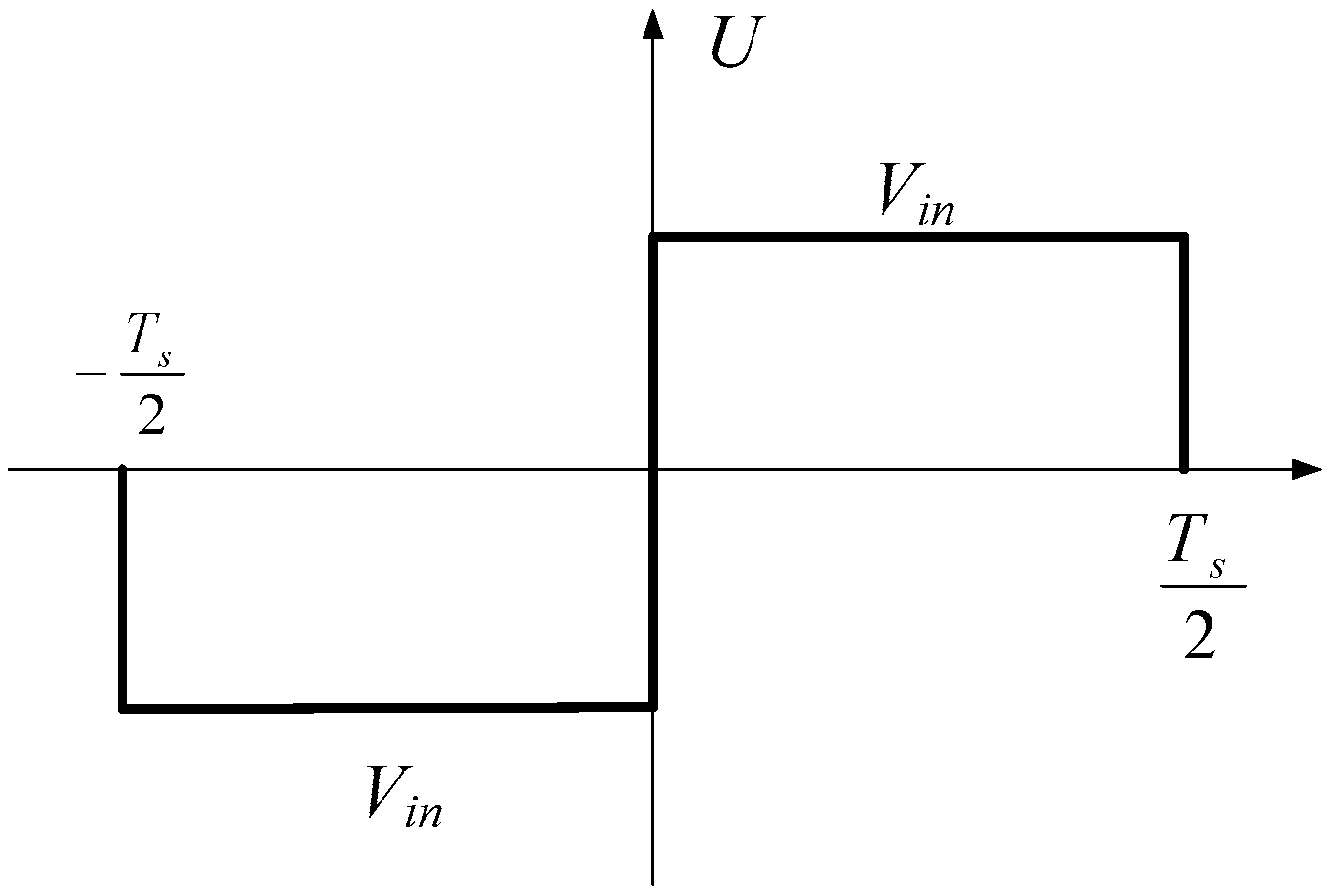
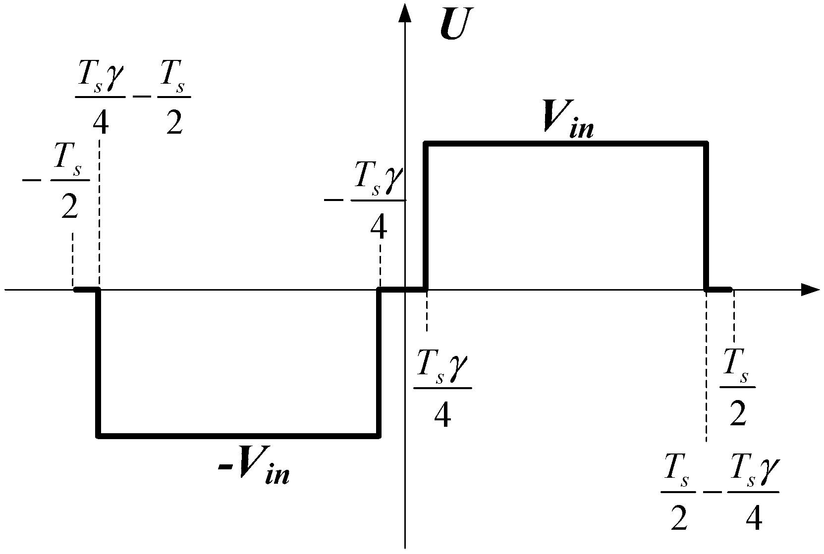
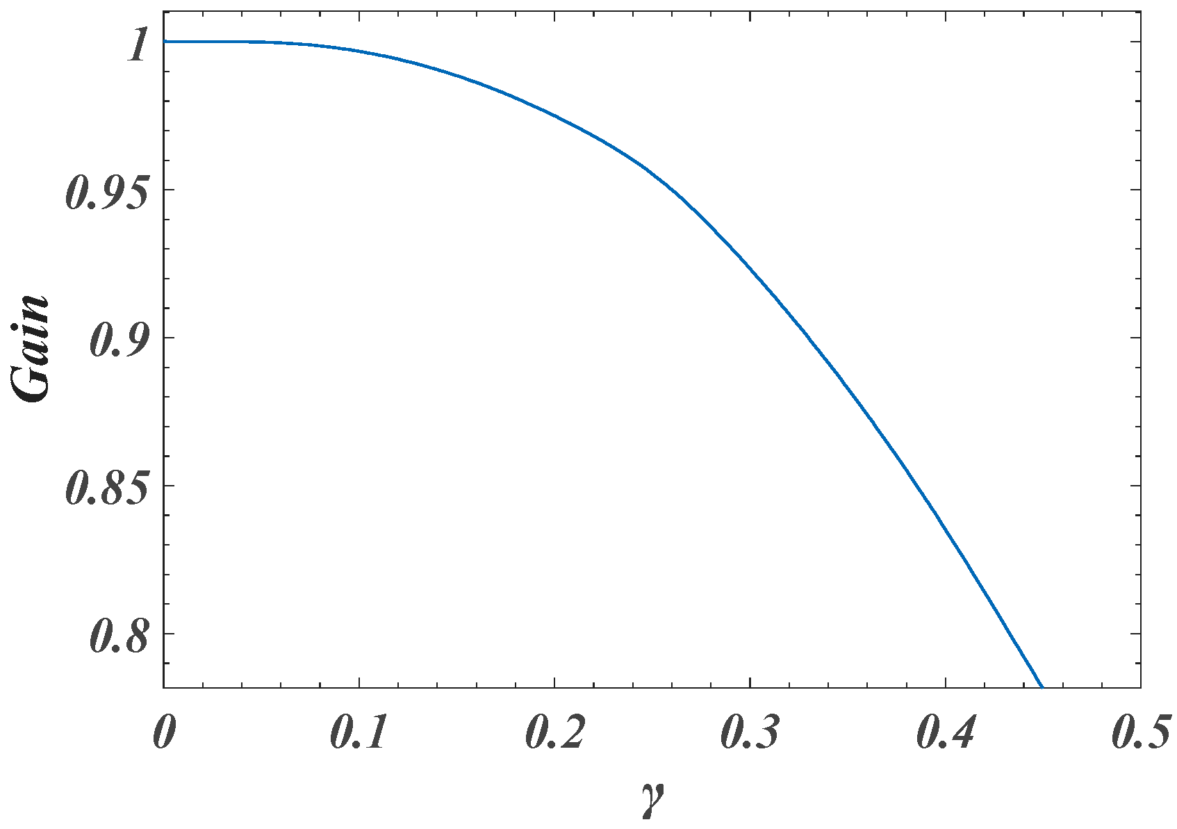
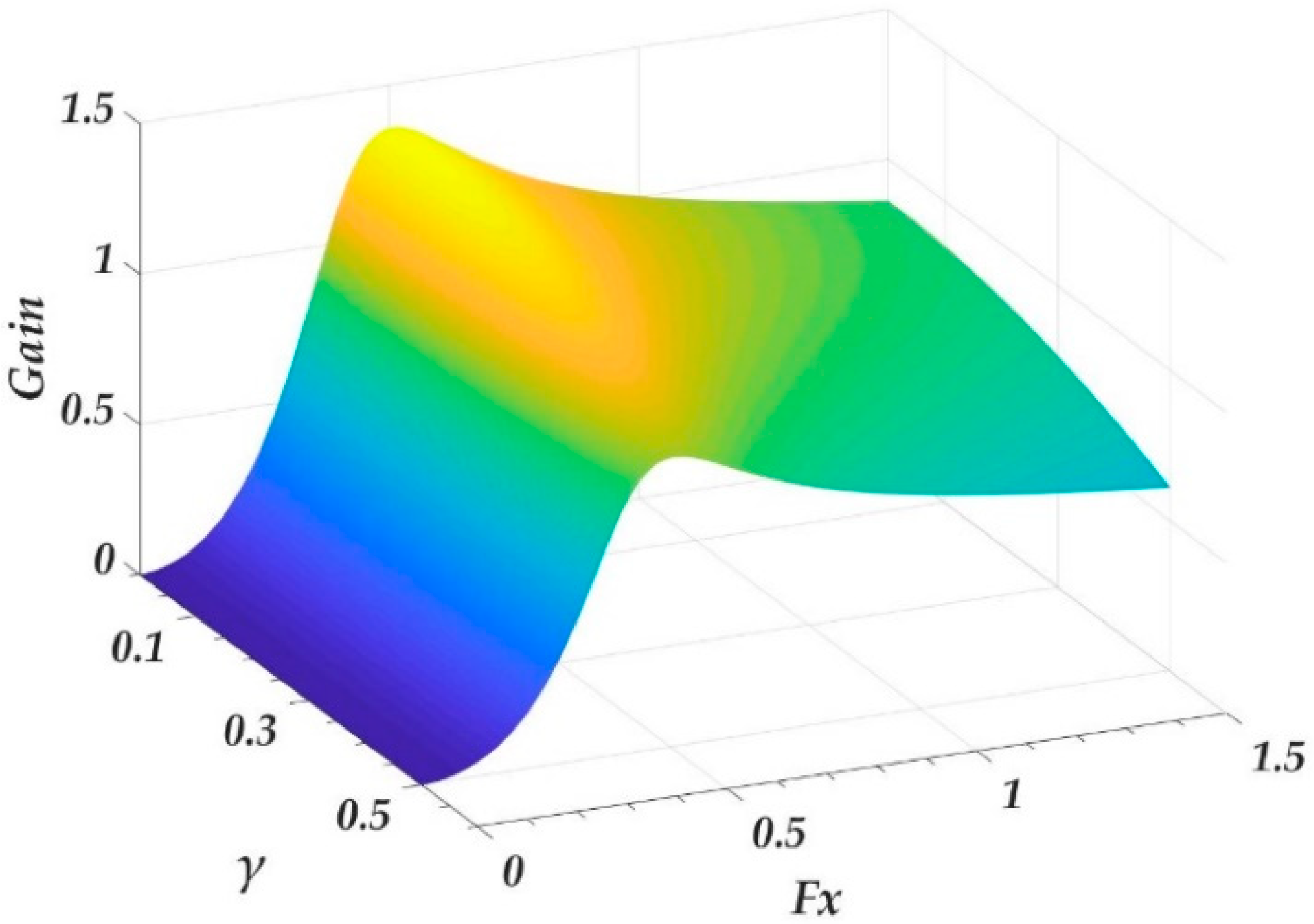
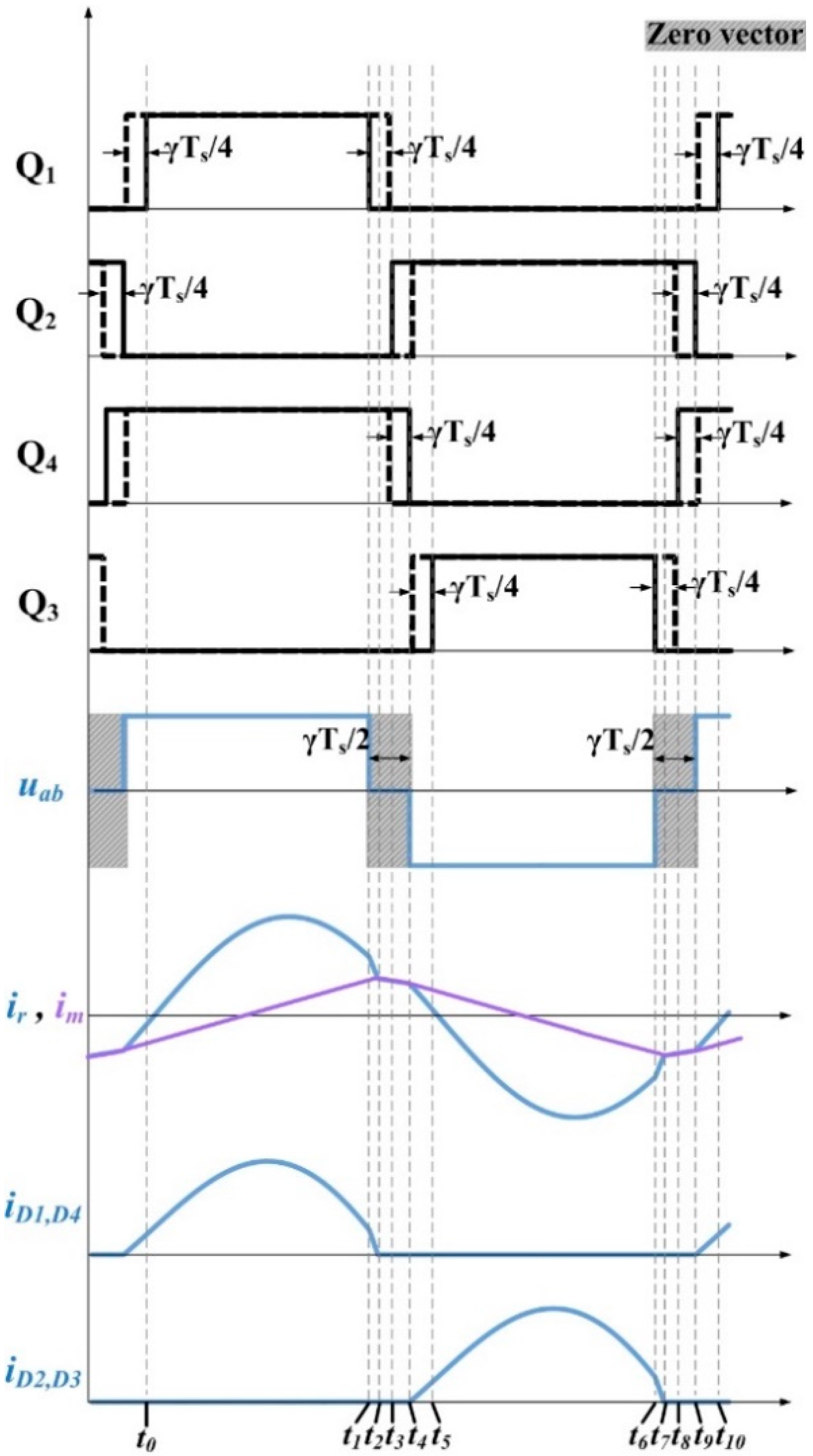
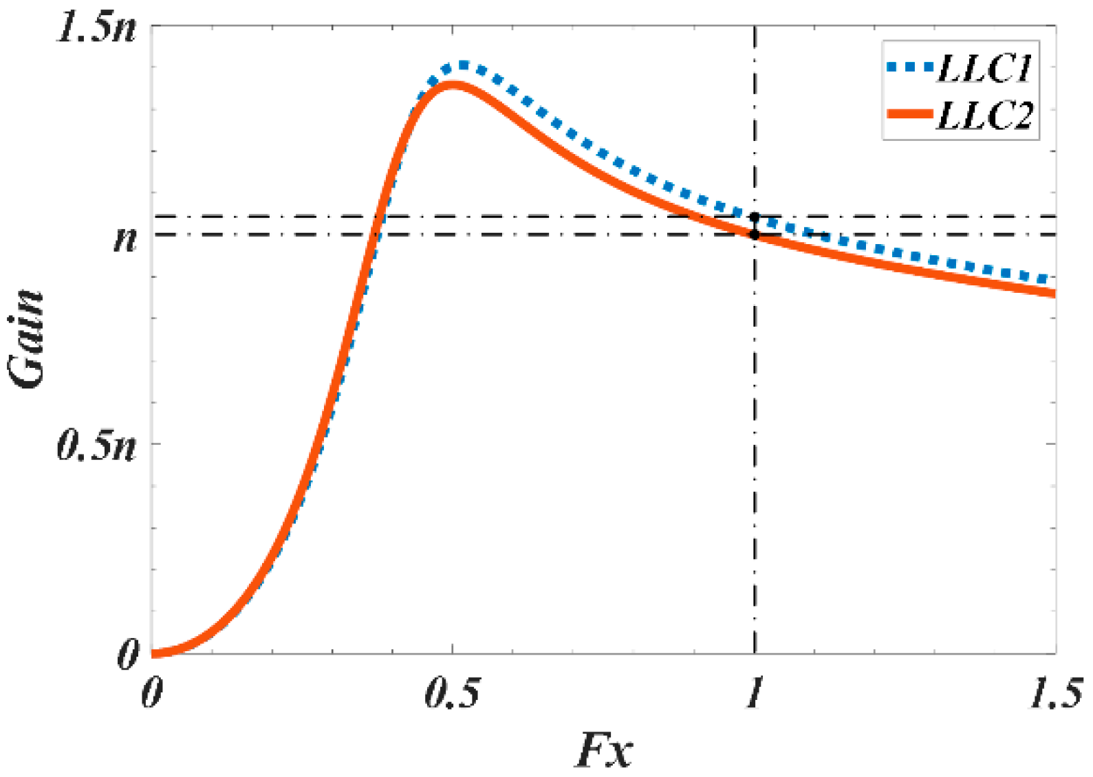
2. Principle of Zero-Vector-Injection Based Current Sharing

The full-bridge LLC converter is shown in Figure 1. The expression of its total gain under PFM control is:
G t = V o u t V i n = G a c × n
where, G a c is the gain of the resonant tank, and 1 / n is the transformer turns ratio.
The voltage applied to the resonant tank, denoted by u a b , is shown in Figure 2. v a b can be expressed as
v a b ( t ) = { V i n ,   ( T s 2 t < 0 ) V i n ,   ( 0 t T s 2 )
where, T s is the switching period.
Fourier series of v a b can be derived,
v a b ( t ) = 4 π V i n n = 1 , 3 , 5 1 n s i n ( n 2 π f s t )
where, f s is the switching frequency.
The fundamental component of v a b is
v a b , F H A ( t ) = 4 π V i n s i n ( 2 π f s t )
Based on First Harmonic Approximation (FHA) [30], the resonant tank gain G a c can be derived by analyzing the equivalent resonant circuit shown in Figure 3. The gain of the resonant tank is a function of Q , k , F x , shown as
G a c ( Q , k , F x ) = k ( F x ) 2 { ( 1 + k ) ( F x ) 2 1 } 2 + { Q × k × F x ( ( F x ) 2 1 ) } 2
k = L m / L r
Q = L r / C r / R a c
R a c = 8 n 2 R L / π 2
f r = 1 / 2 π L r C r
f m = 1 / 2 π ( L r + L m ) C r
F x = f s / f r
where, L m is the magnetizing inductance and L r is the resonant inductance, f r is the resonant frequency.
It can be clearly seen from the above equations, when Q , k and f s are determined, G a c is determined.
After Zero-Vector-Injection, the waveform of v a b is shown in Figure 4. In which, t z is the total length of zero-vector in a switching period, and γ is defined as the zero vector factor
t z = γ T s
The expression of v a b after Zero-Vector-Injection, denoted by v a b , z , in a single period is as follows:
v a b , z ( t ) = { 0 , ( T s 2 t < γ T s 4 T s 2 ) V i n , ( γ T s 4 T s 2 t < γ T s 4 ) 0 , ( γ T s 4 t < γ T s 4 ) V i n , ( γ T s 4 t < T s 2 γ T s 4 ) 0 , ( T s γ T s 4 t T s )
Fourier series of v a b , z can be derived,
v a b , z ( t ) = n = 1 { a n c o s ( n 2 π f s t ) + b n s i n ( n 2 π f s t ) }
where,
a n = 2 T s γ T s 4 T s 2 γ T s 4 ( V i n ) c o s ( n 2 π f s t ) d t + 2 T s γ T s 4 T s 2 γ T s 4 ( V i n ) c o s ( n 2 π f s t ) d t = V i n n π [ s i n ( n 2 π f s t ) γ T s 4 T s 2 γ T s 4 + s i n ( n 2 π f s t ) γ T s 4 T s 2 γ T s 4 ] = 0
b n = 2 T s γ T s 4 T s 2 γ T s 4 ( V i n ) s i n ( n 2 π f s t ) d t + 2 T s γ T s 4 T s 2 γ T s 4 ( V i n ) s i n ( n 2 π f s t ) d t = 2 V i n n π [ c o s ( n π 2 γ ) c o s ( n π π 2 γ ) ] = { 4 V i n n π c o s ( π 2 γ ) n = 1 , 3 , 5 , 7 0 n = 0 , 2 , 4 , 6
Therefore, the Fourier series of the voltage applied to the resonant tank after the Zero-Vector-Injection is
v a b , z ( t ) = 4 V i n π c o s ( π 2 γ ) n = 1 , 3 , 5 1 n s i n ( n 2 π f s t )
The fundamental component of v a b , z is derived,
v a b , z , F H A ( t ) = 4 V i n π c o s ( π 2 γ ) s i n ( 2 π f s t )
It is worth noting that, when zero vector is injected, the voltage applied to the resonant tank has lower THD. Therefore, FHA analysis is usable.
Comparing Equation (4) and Equation (18), the total gain of the full-bridge LLC converter after Zero-Vector-Injection is given by
G t = c o s ( π 2 γ ) × G a c × n
Obviously, the gain of the converter can be adjusted by changing γ . Taking f s = f r as an example, the relationship between γ and G t is shown in Figure 5. According to Equations (5) and (19), the relationship between the gain of the converter and zero vector factor γ and F x is given by Figure 6.
The nature of the current inequality in interleaved LLC converters is gain difference caused by component tolerance. For interleaved LLC converters, the relationship between γ and G t can be used to compensate the differences in gain, to realize current sharing. Specifically, when one phase is providing more current than the other phases, the controller starts to increase γ of the phase providing more current to decrease its output current. Different phases may inject different amounts of zero-vector to achieve load sharing.

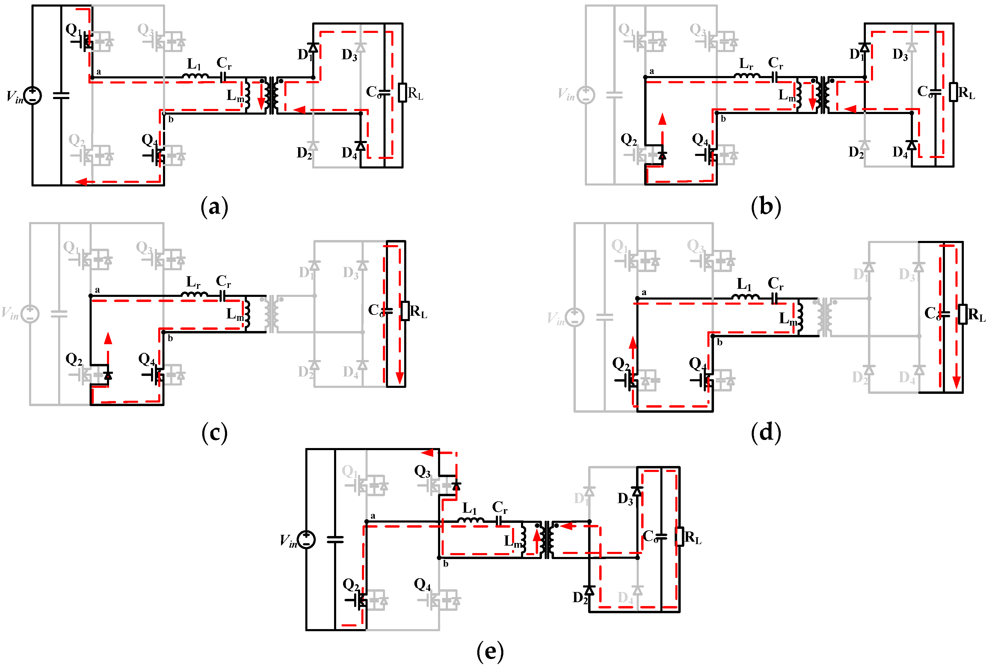
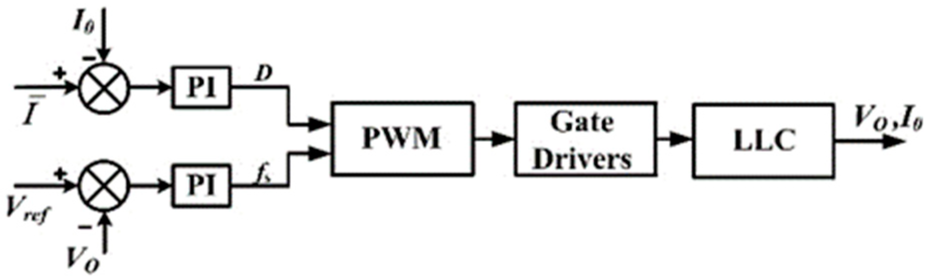
3. Implementation of Zero-Vector-Injection and Soft Switching

For full-bridge topology, there is more than one way to realize Zero-Vector-Injection, such as phase shift modulation [31] and pulse width modulation. Care must be taken to design the modulation scheme. Otherwise, LLC resonant converter may lose soft switching, which is not accepted. In this paper, a novel modulation method based on PWM is proposed and analyzed in detail.
As shown in Figure 7: The waveform shown by the black dotted line is the driving signal of each switching device when zero-vector is not injected, and the switching signal shown by the black solid line is the signal generated by the modulation method proposed in this paper. Compared with the signal before Zero Vector Injection, the turn-on time of Q1 is reduced by γ T s 2 , and the turn-on time of Q2 is increased by γ T s 2 . Meanwhile, the turn-on time of Q3 is reduced by γ T s 2 , and the turn-on time of Q4 is increased by γ T s 2 .
According to Figure 7, the working principle of Zero-Vector-Injection and soft switching are described as follows.
Stage 1 [ t 0 t t 1 ]: During this stage, Q1 and Q4 are turned on. Figure 8a shows the equivalent circuit of stage 1. L r and C r are resonating. D1 and D4 are on, and D2 and D3 are off. The magnetizing inductor L m is clamped by the output voltage, therefore, i m is increasing linearly. The voltage applied to the resonant tank is V i n .
Stage 2 [ t 1 t t 2 ]: This stage is part of the dead time of Q1 and Q2. At t 1 , Q1 is turned off, and the equivalent circuit is shown in Figure 8b. The circuit continues current through a path composed of Q2’s body diode and Q4. At this stage, the voltage applied to the resonant tank is zero, so the resonant current drops rapidly, and the converter still transmits power to the secondary side through the transformer until the i r equals i m at t 2 .
Stage 3 [ t 2 t t 3 ]: This stage is the resting part of the dead time of Q1 and Q2, and the equivalent circuit is shown in Figure 8c. At t 2 stage, i r equals i m , D1 and D4 are off with ZCS. According to the analysis of the previous stage, L m is no longer clamped, L m starts to participate resonance, and resonant current charges the junction capacitor of Q1 and discharges the junction capacitor of Q2, providing conditions for ZVS of Q2. The voltage applied to the resonant tank is zero.
Stage 4 [ t 3 t t 4 ]: At t 3 , Q2 is on with ZVS, and Q2 and Q4 together constitute a continuous current loop, in this stage i r and i m are equal, and L m continues to resonate with L r and C r . This phase ends when Q4 is turned off. During this stage, the voltage applied to the resonant tank is zero.
Stage 5 [ t 4 t t 5 ]: This stage is the dead time of Q4 and Q3, and the current is continued through the loop of the body diode of Q3 and the Q2. At this time, the resonant current charges the junction capacitance of Q4 and discharges the junction capacitance of Q3, which provides conditions for ZVS of Q3. L m is clamped again, the resonant current i r starts to decrease in sinusoidal mode, and the excitation current i m decreases in a certain proportion, and the excitation current is larger than the resonant current. At this time, the D2 and D3 are turned on. When Q3 is on, this stage ends.
Operation principles from t 5 t 10 are similar to stages 1–5 and will not be described in detail here.
From the above analysis, with the proposed modulation strategy, Zero-Vector-Injection of u a b and soft switching (ZVS and ZCS) can be easily realized simultaneously on the condition that the control signal is given before the i r becomes zero.
The system control block diagram is shown in Figure 9, where I 0 is the phase current (resonant current or rectified current), I is the corresponding average current, and D is the duty cycle.
The difference between I 0 and I is sent to a PI controller to adjust the amount of the injected zero-vector (negative value is ignored), thereby realizing current sharing. Moreover, the switching frequency is still determined by the voltage loop.

4. Simulation and Experimental Verification

The simulation model is designed in PLECS. Parameters are listed in Table 1.
When the zero-vector is not injected, the gain curves of the two LLC resonant converters are shown in Figure 10. Due to the difference of parameters, the gain of LLC1 is higher than the gain of LLC2 at the same switching frequency, which will cause an uneven current when interleaved. Simulation results showing uneven currents are shown in Figure 11 and Figure 12.
Current sharing can be achieved by injecting an appropriate amount of zero-vector into the LLC converter which has higher gain. Figure 13 shows two gain curves after the Zero-Vector-Injection. When switching frequency is 100 kHz, the gain of LLC1 and LLC2 have been equalized, which will lead to an even current.
Figure 14, Figure 15 and Figure 16 show the simulation results after using the current sharing strategy proposed in this paper.
Simulation results show that after using the proposed approach, the current of interleaved LLC converters with component tolerance can be equally distributed and soft switching can be realized.
To verify the feasibility of the proposed current sharing strategy, a two-phase LLC resonant converter prototype is designed (Rated power 1.7 kW, input voltage 28 V, and output voltage 180 V), as shown in Figure 17. The design parameters of the converters are shown in Table 2.
Due to the inevitable deviation of component parameters, the current of the two-phase LLC resonant converter is not uniform when no current sharing control is applied. For the half load, Figure 18 shows the current after the rectifier bridge, denoted by I r e c t in Figure 18a, of two phases without current sharing control. The peak difference is 1.3 A. After using the current sharing strategy proposed in this paper, the peak difference has been reduced significantly, which is only 280 mA. The results at full load are shown in Figure 19, denoted by I r e c t in Figure 19a. When the proposed current sharing strategy is applied, the current difference between each phase is reduced to 460mA. Moreover, ZCS of the secondary side is realized.
In Figure 20, V a b , z is the voltage applied to the resonant tank after Zero-Vector-Injection. Obviously, ZVS can still be realized after using the proposed current sharing strategy.
Temperatures of these MOSFET under different operating conditions provides an indication of the effectiveness of the current sharing strategy proposed in this paper. The temperature of MOSFET at the rated power is detected using thermal cameras, as shown in Figure 21a,b.
According to Figure 21a, phase two has a higher temperature than phase one when current sharing is disabled. With current sharing, the difference in temperature between the two phases is very small, as shown in Figure 21b.
As mentioned in Section 1, the current sharing strategy proposed in this paper can also improve the efficiency of the parallel system by using phase shedding technique. Figure 22 shows the phase shedding waveform when the load current is less than 55%. When the load current is below 5.5 A, phase two is shut down. As shown in Figure 23, the 5 A (50%) load efficiency is improved from 93% to above 94%, and the 2 A (20%) load efficiency is improved from 85% to 90%. Considering that this is a high step-up ratio application, this efficiency performance is acceptable.

5. Conclusions

In this paper, a novel current sharing strategy for interleaved full-bridge LLC resonant converters based on Zero-Vector-Injection is proposed, which can realize current sharing without adding any additional hardware. The principle of Zero-Vector-Injection is analyzed based on FHA. A detailed modulation scheme is proposed to realize ZVS and ZCS when Zero-Vector-Injection is activated. Theoretical analysis and simulation confirm the feasibility of the proposed method in this paper. To further verify the proposed approach, a two-phase interleaved LLC converter prototype with 1.8 kW rated power was built. Experiment results from the prototype show very good load sharing performance. Moreover, the use of the phase shedding technique improves light-load efficiency significantly.

Author Contributions

Conceptualization, X.W. (Xuanlyu Wu) and D.L.; Methodology, X.W. (Xuanlyu Wu), D.L. and P.W.; Software, D.L.; Validation, D.L. and P.W.; Formal analysis, X.Z. and Z.K.; Writing—original draft preparation, D.L.; Writing—review and editing, X.W. (Xuanlyu Wu) and D.L.; Visualization, D.L.; Supervision, X.W. (Xuanlyu Wu); Project administration, X.W. (Xiaohua Wu); Funding acquisition, X.W. (Xiaohua Wu). All authors have read and agreed to the published version of the manuscript.

Funding

This work is funded by the National Natural Science Foundation of China (51707160), the seed Foundation of Innovation and Creation for Graduate Students in Northwestern Polytechnical University (ZZ2019025), and the Fundamental Research Funds for the Central Universities (3102016OQD0114).

Acknowledgments

This study was supported by Northwestern Polytechnical University.

Conflicts of Interest

The authors declare no conflicts of interest.

References

  1. Hussain, H.; Seung-Woo, B.; Hag-Wone, K.; Kwan-Yuhl, C. Circuit Topology and small signal modeling of variable duty cycle controlled three-level LLC conver. Energies 2019, 12, 3833. [Google Scholar]
  2. Eun-Soo, K.; Jae-Sung, O. High-efficiency bidirectional LLC resonant converter with primary auxiliary windings. Energies 2019, 12, 4692. [Google Scholar]
  3. Fang, L.; Ruixiang, H.; Haodong, L.; Xinyi, Z. The influence of parasitic components on LLC resonant converter. Energies 2019, 12, 4305. [Google Scholar]
  4. Hiroki, W.; Jun-ichi, I.; Naoki, K.; Shinichiro, N. PV Micro-inverter topology using LLC resonant converter. Energies 2019, 12, 3106. [Google Scholar]
  5. Yang, B.; Lee, F.C.; Zhang, A.J.; Huang, G. LLC resonant converter for front end DC/DC conversion. In Proceedings of the IEEE 17th Annual Applied Power Electron Conference and Exposition, Dallas, TX, USA, 10–14 March 2002; Volume 2, pp. 1108–1112. [Google Scholar]
  6. Musavi, F.; Craciun, M.; Gautam, D.S.; Eberle, W.; Dunford, W.G. An LLC resonant DC–DC converter for wide output voltage range battery charging applications. IEEE Trans. Power Electron. 2013, 28, 5437–5445. [Google Scholar] [CrossRef]
  7. Batarseh, I. Resonant converter topologies with three and four energy storage elements. IEEE Trans. Power Electron. 1994, 9, 64–73. [Google Scholar] [CrossRef]
  8. Lu, B.; Liu, W.; Liang, Y.; Lee, F.C.; Van Wyk, J.D. Optimal design methodology for LLC resonant Converter. In Proceedings of the IEEE 21th Annual Applied Power Electron Conference Exposition, Dallas, TX, USA, 19–23 March 2006; pp. 533–538. [Google Scholar]
  9. Xiaogao, X.; Junming, Z.; Chen, Z.; Zhuo, Z.; Zhaoming, Q. Analysis and optimization of LLC resonant converter with a novel over-current protection circuit. IEEE Trans. Power Electron. 2007, 22, 435–443. [Google Scholar]
  10. Bong-Chul, K.; Ki-Bum, P.; Chong-Eun, K.; Byoung-Hee, L.; Gun-Woo, M. LLC resonant converter with adaptive link-voltage variation for a high-power-density adapter. IEEE Trans. Power Electron. 2010, 25, 2248–2252. [Google Scholar]
  11. Hang, L.; Li, B.; Liu, S.; Gu, Y.; Yao, W.; Lu, Z. Asymmetrical secondary structure of LLC series resonant DC/DC converter for multi-output applications. IET Power Electron. 2011, 4, 993–1001. [Google Scholar] [CrossRef]
  12. Huang, D.; Ji, S.; Lee, F.C. LLC Resonant converter with matrix transformer. IEEE Trans. Power Electron. 2014, 29, 4339–4347. [Google Scholar] [CrossRef]
  13. Kim, M. Two-phase interleaved LLC resonant converter with phase shedding control. In Proceedings of the 2010 International Power Electronics Conference (ECCE ASIA), Sapporo, Japan, 21–24 June 2010; pp. 1642–1645. [Google Scholar]
  14. Jin, T.; Smedley, K. Multiphase LLC series resonant converter for microprocessor voltage regulation conference record. In Proceedings of the IEEE Industry Applications Conference Forty-First IAS Annual Meeting, Tampa, FL, USA, 8–12 October 2006; pp. 2136–2143. [Google Scholar]
  15. Figge, H.; Grote, T.; Froehleke, N.; Boecker, J.; Ide, P. Paralleling of LLC resonant converters using frequency controlled current balancing. In Proceedings of the IEEE Power Electronics Specialists Conference, Rhodes, Greece, 15–19 June 2008; pp. 1080–1085. [Google Scholar]
  16. Lin, B.; Yang, W.; Chen, J.; Huang, C.; Yu, M. Interleaved LLC series converter with output voltage doubler. In Proceedings of the 2010 International Power Electronics Conference (ECCE ASIA), Sapporo, Japan, 21–24 June 2010; pp. 92–98. [Google Scholar]
  17. Kim, B.-C.; Park, K.-B.; Kim, C.-E.; Moon, G.-W. Load sharing characteristic of two-phase interleaved LLC resonant converter with parallel and series input structure. In Proceedings of the IEEE Energy Conversion Congress and Exposition, San Jose, CA, USA, 20–24 September 2009; pp. 750–753. [Google Scholar]
  18. Kim, B.; Park, K.; Moon, G. Analysis and design of two-phase interleaved LLC resonant converter considering load sharing. In Proceedings of the IEEE Energy Conversion Congress and Exposition, San Jose, CA, USA, 20–24 September 2009; pp. 1141–1144. [Google Scholar]
  19. Hu, Z.; Qiu, Y.; Liu, Y. Digital implementation of load sharing method for interleaved LLC converters. In Proceedings of the IEEE 14th Workshop on Control and Modeling for Power Electronics (COMPEL), Salt Lake City, UT, USA, 3–26 June 2013; pp. 1–7. [Google Scholar]
  20. Hu, Z.; Qiu, Y.; Liu, Y.; Sen, P.C. A control strategy and design method for interleaved LLC converters operating at variable switching frequency. IEEE Trans. Power Electron. 2014, 29, 4426–4437. [Google Scholar] [CrossRef]
  21. Orietti, E.; Mattavelli, P.; Spiazzi, G.; Adragna, C.; Gattavari, G. Two-phase interleaved LLC resonant converter with current-controlled inductor. In Proceedings of the Brazilian Power Electronics Conference, Bonito-Mato Grosso do Sul, Brazil, 27 September–1 October 2009; pp. 298–304. [Google Scholar]
  22. Wang, H.; Chen, Y.; Liu, Y.; Afsharian, J.; Yang, Z. A passive current sharing method with common inductor multiphase LLC resonant converter. IEEE Trans. Power Electron. 2017, 32, 6994–7010. [Google Scholar] [CrossRef]
  23. Wang, H.; Chen, Y.; Hu, Z.; Wang, L.; Qiu, Y.; Liu, W.; Liu, Y.; Afsharian, J.; Yang, Z. A common capacitor multi-phase LLC resonant converter. In Proceedings of the IEEE Applied Power Electronics Conference and Exposition (APEC), Long Beach, CA, USA, 20–24 March 2016; pp. 2320–2327. [Google Scholar]
  24. Wang, H.; Chen, Y.; Liu, Y. A passive-impedance-matching technology to achieve automatic current sharing for a multiphase resonant converter. IEEE Trans. Power Electron. 2017, 32, 9191–9209. [Google Scholar] [CrossRef]
  25. Sato, M.; Takiguchi, R.; Imaoka, J.; Shoyama, M. A novel secondary PWM-controlled interleaved LLC resonant converter for load current sharing. In Proceedings of the IEEE 8th International Power Electronics and Motion Control Conference (IPEMC-ECCE Asia), Hefei, China, 22–26 May 2016; pp. 2276–2280. [Google Scholar]
  26. Sun, J.; Tang, X.; Xing, Y.; Chen, B.; Wu, H.; Sun, K. Current sharing control of interleaved LLC resonant converter with hybrid rectifier. In Proceedings of the IEEE Applied Power Electronics Conference and Exposition (APEC), Anaheim, CA, USA, 17–21 March 2019; pp. 2223–2227. [Google Scholar]
  27. Mostafa, N.; Shun, E.; Hiroki, I.; Kimihiro, N. A current sharing method utilizing single balancing transformer for a multiphase LLC resonant converter with integrated magnetics. IEEE J. Emerg. Sel. Top. Power Electron. 2018, 1. [Google Scholar] [CrossRef]
  28. Kirshenboim, O.; Peretz, M.M. Combined multilevel and two-phase interleaved LLC converter with enhanced power processing characteristics and natural current sharing. IEEE Trans. Power Electron. 2018, 33, 5613–5620. [Google Scholar] [CrossRef]
  29. Tada, Y.; Sato, Y.; Uno, M. Three-phase interleaved LLC converter with capacitive current balancing and reduced switch voltage stress. In Proceedings of the 10th International Conference on Power Electronics and ECCE Asia (ICPE 2019-ECCE Asia), Busan, Korea, 27–31 May 2019; pp. 1–7. [Google Scholar]
  30. De Simone, S.; Adragna, C.; Spini, C.; Gattavari, G. Design-oriented steady-state analysis of LLC resonant converters based on FHA. In Proceedings of the International Symposium on Power Electronics, Electrical Drives, Automation and Motion, SPEEDAM, Taormina, Italy, 23–26 May 2006; pp. 200–207. [Google Scholar]
  31. Murata, K.; Kurokawa, F. An Interleaved PFM LLC Resonant converter with phase shift compensation. IEEE Trans. Power Electron. 2015, 31, 2264–2272. [Google Scholar] [CrossRef]
Figure 1. Full-bridge LLC converter.
Energies 13 00347 g001
Figure 2. v a b without Zero-Vector-Injection.
Energies 13 00347 g002
Figure 3. The equivalent resonant circuit.
Energies 13 00347 g003
Figure 4. v a b with Zero-Vector-Injection.
Energies 13 00347 g004
Figure 5. The relationship between total gain of LLC resonant converter and γ at f s = f r .
Energies 13 00347 g005
Figure 6. The relationship between total gain of LLC resonant converter and γ and F x .
Energies 13 00347 g006
Figure 7. Key waveforms of the proposed Zero-Vector-Injection strategy.
Energies 13 00347 g007
Figure 8. Equivalent circuits for various stages of operation: (a) [ t 0 t 1 ]; (b) [ t 1 t 2 ]; (c) [ t 2 t 3 ]; (d) [ t 3 t 4 ]; (e) [ t 4 t 5 ].
Energies 13 00347 g008
Figure 9. The control block diagram.
Energies 13 00347 g009
Figure 10. The gain curve of two LLC resonant converters.
Energies 13 00347 g010
Figure 11. Resonant current without current sharing.
Energies 13 00347 g011
Figure 12. Output current without current sharing.
Energies 13 00347 g012
Figure 13. Gain curves of two LLC resonant converters after Zero-Vector-Injection.
Energies 13 00347 g013
Figure 14. Vab, VDS and VGS with the proposed current sharing strategy.
Energies 13 00347 g014
Figure 15. Resonant current with the proposed current sharing strategy.
Energies 13 00347 g015
Figure 16. Output current with the proposed current sharing strategy.
Energies 13 00347 g016
Figure 17. Prototype of 2-phase interleaved LLC resonant converter. (a) Overall control Block diagram; (b) Hardware.
Energies 13 00347 g017
Figure 18. Output current between phases at half load. (a) without the proposed current sharing strategy; (b) with the proposed current sharing strategy.
Energies 13 00347 g018
Figure 19. Output current between phases at full load. (a) without the proposed current sharing strategy; (b) with the proposed current sharing strategy.
Energies 13 00347 g019
Figure 20. The waveform of zero voltage turn-on.
Energies 13 00347 g020
Figure 21. Thermal images at full load. (a) without proposed current sharing strategy; (b) with the proposed current sharing strategy.
Energies 13 00347 g021
Figure 22. Phase shedding operation (Transition from full load to half load).
Energies 13 00347 g022
Figure 23. Efficiency with and without phase shedding.
Energies 13 00347 g023
Table 1. Parameters of the simulation model.
ParameterSymbolValue
Input Voltage V i n 28 V
Output Voltage V o u t 180 V
Turns Ratio 1 / n 3:20
Resonant Capacitance C r 1
C r 2
95 nF
100 nF
Resonant Inductance L r 1
L r 2
26 μH
25 μH
Magnetizing Inductance L m 1
L m 2
125 μH
126 μH
Switching Frequency f s 100 kHz
Phase-shiftα90°
Table 2. Parameters of the prototype.
ParameterSymbolValue
Input Voltage V i n 28 V
Output Voltage V o u t 180 V
Rated Power P o 1 , P o 2 900 W
Turns Ratio 1 / n 3:20
Resonant Capacitance C r 100 nF
Resonant Inductance L r 25 μH
Magnetizing Inductance L m 125 μH
Switching Frequency f s 95 kHz
Phase-shiftα90°

