Article

Optimization of Energy Management Strategy for the EPS with Hybrid Power Supply Based on PSO Algorithm

1
Automotive Engineering Research Institute, Jiangsu University, Zhenjiang 212013, China
2
School of Automotive and Traffic Engineering, Jiangsu University, Zhenjiang 212013, China
*
Author to whom correspondence should be addressed.
Energies 2020, 13(2), 428; https://doi.org/10.3390/en13020428
Submission received: 18 December 2019 / Revised: 9 January 2020 / Accepted: 15 January 2020 / Published: 16 January 2020

Abstract

:
The traditional vehicle power supply is unable to meet the power requirement of electric power steering system (EPS) in heavy-duty vehicles at low speeds. A novel EPS with hybrid power supply (HP-EPS) is constructed in this paper, and a new optimized rule-based energy management strategy of hybrid power supply system is designed. The strategy determines the power distribution of the vehicle power supply (VPS) and super capacitor (SC), as well as the charging or discharging of SC. Furthermore, to minimize the output current fluctuation of the VPS, the optimization model of parameters in the strategy is established and the particle swarm optimization algorithm (PSO) algorithm is applied to optimize the rules in the energy management strategy. The verification for the designed energy management strategy is carried out in MATLAB/Simulink and results show that the output current peak of VPS decreases by 33% and its fluctuation depresses significantly. In addition, the SC is charged timely and fast, which is beneficial to guarantee enough state of charge (SOC) of SC. In conclusion, the optimized rule-based energy management strategy used for the HP-EPS system can meet the current requirement of EPS and effectively reduce the peak and fluctuation of the VPS output current.

Graphical Abstract

1. Introduction

Recently, electric power steering (EPS) has been widely used in passenger cars due to its safety, energy saving, and environmental protection [1,2,3]. However, the traditional power supply in vehicles can only provide limited electric power which is not enough to let the EPS work normally on heavy-duty vehicles such as agricultural transport vehicles, trucks, and medium and large coaches [4,5]. The steering resistance torque is especially large when the vehicle is turning at low speeds, so the corresponding required steering power is far beyond the rated output power of the vehicle power supply (VPS). For example, when a heavy-duty vehicle whose front load is 6000 kg turns at a low speed, the required power of EPS is about 4 kW and the current is about 200 A. Sometimes, the current could reach to 250 A. In this condition, the power/current requirement for EPS is far beyond the power supply capacity of VPS. Vehicles usually run in a medium or high speed, when the VPS can provide sufficient current to overcome the corresponding small steering resistance torque [6]. Therefore, it is necessary to focus on solving the problem of insufficient power provided by the VPS in the vehicles when turning at low speeds to promote the application of EPS on heavy-duty vehicles. Based on the advantages of super capacitor (SC) with high power density, short charging time, and high-current discharging capacity [7,8,9], the EPS with hybrid power supply (HP-EPS) composed by a VPS and a SC is constructed in this study. The energy management is: When the vehicle speed is low, the VPS and SC provide the steering power for the EPS together. When the vehicle speed is high, the VPS provides steering power alone for the EPS and charge the SC if its SOC is low.
The power distribution of the VPS and SC in the HP-EPS, and the SC mode switching of charge or discharge are determined by energy management strategy. The energy management strategy used for hybrid power system mainly includes the rule-based energy management strategy [10], the experience-based energy management strategy [11], and the optimization-based energy management strategy which is widely used in the area of vehicles’ power distribution [12]. Some scholars have used the NSGA-II multi-objective algorithm to optimize the matching and energy management strategy parameters of hybrid power system in electric vehicles [13,14]; some researchers have used convex optimization to match the parameters of hybrid power system and optimize the energy management strategy [15,16]; and some scholars have used model predictive control algorithm [17,18], dynamic programming algorithm [19,20,21], and fuzzy logic control algorithm [22] to optimize the energy management strategy of hybrid power system. At present, these researches on hybrid power supply in vehicles and its energy management strategy are mainly aimed at the power system used for new energy vehicles which composed by power battery and SC, while the new hybrid power supply composed of the VPS and SC and its energy management strategy have rarely studied.
Based on the analysis of the current requirement of EPS and compared these referred energy management strategies, the HP-EPS system is constructed and an optimized rule-based energy management strategy based on PSO algorithm for the HP-EPS system is proposed. The proposed energy management strategy determines the current distribution of the VPS and SC as well as the charging and discharging strategy of SC. An optimization model of parameters in the energy management strategy is established with the goal of minimizing the fluctuation of output current of the VPS, and parameters of the optimized rule-based energy management strategy are obtained based on the PSO algorithm. Finally, compared the output current of VPS after being distributed by the optimized rule-based energy management strategy with the required current of EPS, the effectiveness of the optimized rule-based energy management strategy is verified.

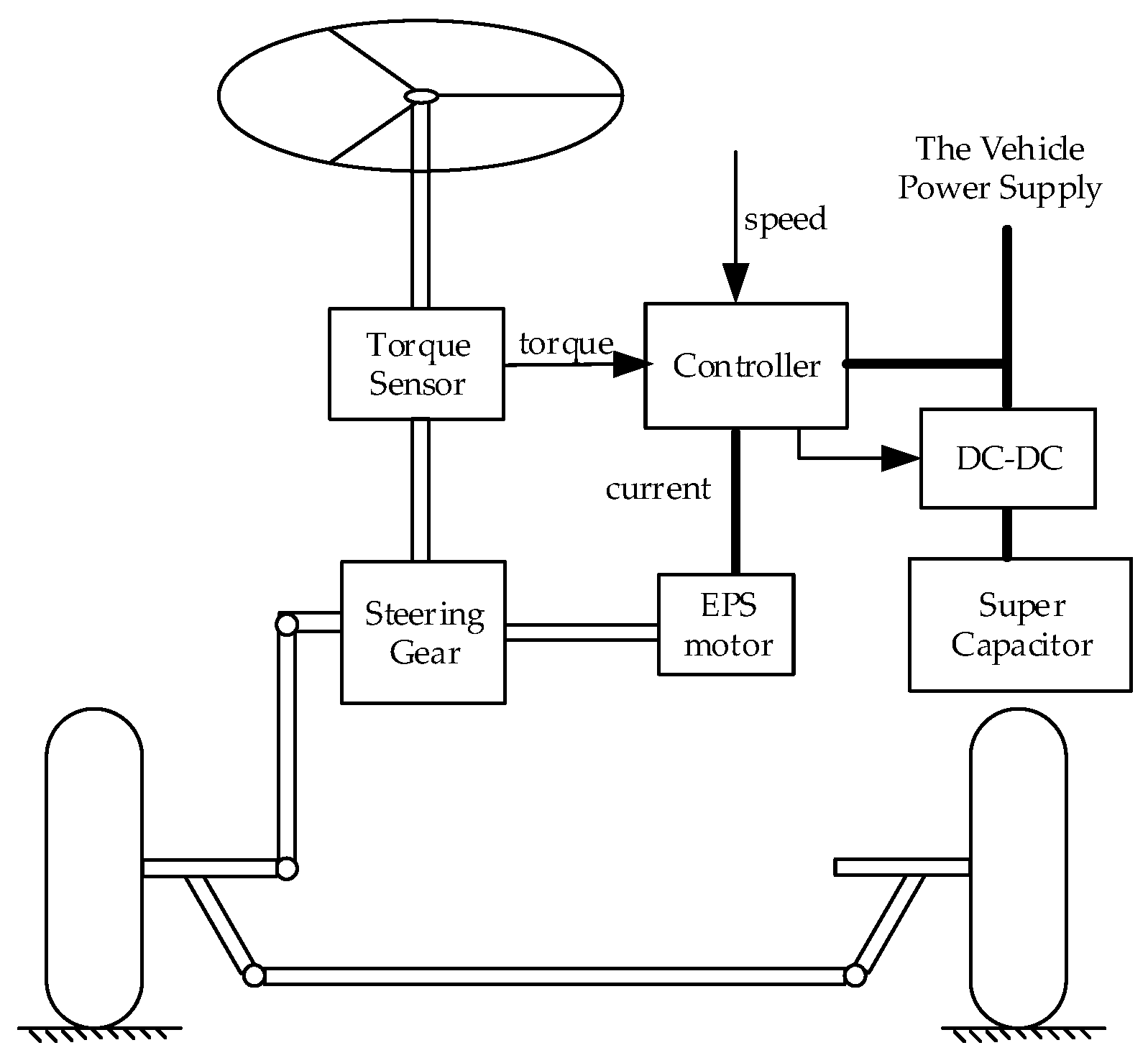
2. The Structure and Principle of HP-EPS

The structure of the HP-EPS is shown in Figure 1, including the torque/angle sensor, recirculating ball steering gear, assist motor, controller, DC/DC converter and super capacitor. The super capacitor is connected in parallel with the vehicle power system through the DC/DC converter to form the hybrid power system. The VPS is the generator in test vehicle with a rated current of 140 A, and the capacitance of the SC is 250 F. In the HP-EPS system, the inputs are vehicle speed and torque of steering wheel, the output is the current distribution between the VPS and SC. There are three power supply modes of the HP-EPS system, namely, the hybrid power supply mode, the VPS supply mode, and SC supply mode. When the vehicle speed is low, the HP-EPS system works in the hybrid power supply mode. In this case, the VPS and the SC jointly provide steering power for the EPS and the controller determines the proportion of power distribution based on the designed energy management strategy according to real-time vehicle speed, steering wheel torque and state of charge (SOC) of SC. When the vehicle speed is high, the HP-EPS system works in the vehicle power supply mode. In this case, the VPS system provides steering power for the EPS individually, and controller determines to charge the SC or not according to the real-time SOC of SC based on the designed energy management strategy. When the VPS breaks down, the HP-EPS system is in the SC supply mode. In this case, the SC can emergently provide steering power to the EPS to maintain short-term steering assistance.

3. The Mathematical Model of HP-EPS

The mathematical model [23] of HP-EPS mainly includes a steering wheel, an input shaft, a recirculating ball steering gear, a power-assisted motor, and a super capacitor. Its schematic of dynamic model is shown in Figure 2.
J h w θ ¨ h w + B h w θ ˙ h w + K t ( θ h w θ e ) = T h w
J m θ ¨ m + B m θ ˙ m = k a i T a / G
J c θ ¨ e + B c θ ˙ e = K t ( θ h w θ e ) + T a P F L / 2 π
m L x ¨ m + b L x ˙ m = F L F c s
J c s θ ¨ c s + B c s θ ˙ c s = F c s R c s T p
U = L d i d t + R i + K e d θ m d t
where J h w is the moment of inertia of steering wheel, B h w is the damping coefficient of steering wheel, K t is the stiffness of torsion bar, θ h w is the rotational angle of steering wheel, θ e is rotational angle of screw ( θ e = 2 π P x m ), θ m is the rotational angle of screw ( θ m = G · θ e ), T h w is the torque of steering wheel, G is the transmission ration of turbine shaft, J m is the moment inertia of motor, B m is the damping coefficient of steering wheel, J c is the moment inertia of screw, B c is the coefficient of screw, P is the lead of screw, F L is the thrust of the screw, m L is the mass of steering nut, b L is the damping coefficient of steering nut, x m is the displacement of screw nut ( x m = R c s θ c s ), J c s is the moment inertia of sector, B c s is the damping coefficient of sector, θ c s is the rotational angle of screw, F c s is the acting force of sector, R c s is the pitch radius of sector, T p is the steering resistance torque, U is the terminal voltage of the motor, L is the inductance of motor, R is the resistance of motor, i is the current of motor, K e is the counter electromotive force coefficient of motor, k a is the torque coefficient of motor, and T a is the steering torque.
The calculation of SOC in SC [24] is shown as follow,
S O C = U U min U max U min
where U is the terminal voltage of super capacitor ( U = U ' I Δ t C ), U’ is the previous terminal voltage of super capacitor, C is the capacitance of super capacitor, I is the charging or discharging current of super capacitor, U min is the minimum terminal voltage of super capacitor ( U min = 12 V ), and U max is the maximum terminal voltage of super capacitor ( U max = 24 V ).

4. The Energy Management Strategy of HP-EPS

The required current of EPS is especially large when the vehicle is turning at low speeds, and it decreases with the speed reduction of vehicle. The large fluctuation of EPS current requirement during the test condition causes that the output current of the VPS fluctuates wildly and even is insufficient. Therefore, the charging/discharging of SC needs to be controlled timely to play the role of ‘peak-cutting and valley-filling’ and effectively smooth the output current of the VPS. The rule-based energy management strategy is proposed for the HP-EPS (as shown in Table 1), which determines the current distribution of the VPS and SC as well as the switching between charging and discharging mode of super capacitor.
In Table 1, I r e q is the required current of EPS which is obtained by looking up the assist characteristics according to steering torque and vehicle speed, I l o w and I h i g h are both current thresholds which will be compared with I r e q to judge and execute different control strategies of current distribution, S O C t o p and S O C b o t are respectively the upper limit value and lower limit value of SOC ( S O C t o p = 0.8 , S O C b o t = 0.2 ) which will be compared with the real-time SOC to determine the working mode of SC, I g is the output current of the VPS, I s c D is the discharging current of SC, and I s c C is the charging current of SC.
The control strategies are illustrated as follows. Firstly, the controller receives the signals of vehicle speed and steering torque and acquires EPS required current I r e q according to the EPS assist characteristics. Secondly, the I r e q is compared with both I l o w and I h i g h . At the same time, SOC of SC is calculated and compared with S O C t o p and S O C b o t . Thirdly, the distribution current of the VPS and the SC or the charging current of SC are determined. Finally, the controller sends the signal to the DC/DC converter to control the charging and discharging of the SC, which indirectly controls the output current of the VPS. For example, if I r e q is lower than I l o w , the controller will be judged that the current load of VPS is too small, so the SOC of SC will be checked and if it is lower than S O C t o p , the discharge current of the VPS will be increased to I l o w and I s c C is equals to I l o w I r e q .

5. Optimization of Parameters in the Rule-Based Energy Management Strategy

In the energy management strategy, the current threshold parameters I l o w and I h i g h will influence the current distribution of the SC and the VPS, so the proper selection of I l o w and I h i g h is important. If I h i g h is set too large, the output current of the VPS will be large, and it is difficult for the super capacitor to exert its role of ‘peak-cutting and valley-filling’. If I h i g h is set too small, the super capacitor will discharge heavily, which is likely to cause insufficient energy of SC and further result in the malfunction of EPS. Similarly, if I l o w is set too small, it will not be able to effectively reduce the output current fluctuation of the VPS. If I l o w is set too large, the SC will have less time to charge and cause insufficient power supply of the SC. Therefore, the threshold current parameters should be optimized. In this paper, a particle swarm optimization algorithm (PSO) is used to optimize the threshold current parameters so that the output current fluctuation of the VPS could be as small as possible, at the same time ensuring that the SOC of the SC is in a reasonable range. PSO is a bio-derived algorithm, whose particles have better social cognitive properties and individual cognitive capabilities, move to space where better solution might exist driven by the global and individual historical optimization, which is more efficient than other heuristics algorithm [25].

5.1. Optimization Model of Energy Management Strategy

This study focuses on making full use of the “peak-cutting and valley-filling” capability of super capacitor to minimize the output current fluctuation of the VPS. By accumulating the difference of the output current of the VPS between the last moment and now, a sum value is obtained which represents the current fluctuation of the vehicle power supply. A large sum value means a great fluctuation of output current. Otherwise, a small sum means a small fluctuation of output current. So, a smaller sum value is the optimization objection. The established optimization model is shown in Equation (8).
{ min F ( x ) = i = 0 n | I g i ( i + 1 ) I g i ( i ) | x = [ I l o w , I h i g h ] x L x x H
where F ( x ) is the objective function which represents the output current fluctuation of VPS, I l o w and I h i g h are both optimization variables and [ x L , x H ] is the limitation of optimization variables, considering the current consumption of other electric appliances ( x H = 100 A , x L = 0 A ).

5.2. Fitness Model

The fitness model is established in MATLAB/Simulink as shown in Figure 3. The inputs are the required current of EPS I r e q , the real-time SOC, the two initiated current threshold parameters I l o w and I h i g h . According to these inputs, the energy management strategy program, which is interpreted to Matlab code based on Table 1, calculates and distributes the output current of the VPS I g and the charging current I s c C or discharging current I s c D of SC. The quantity of electric charge of SC is obtained by the integral of I s c C or I s c D . Adding the obtained quantity of electric charge and the remaining quantity of electric charge of SC, the updated SOC of the super capacitor is obtained by Equation (7) and the output current of the VPS I g is updated. Finally, the real-time current fluctuation is obtained by accumulating the real-time I g in the PSO program.

5.3. Process and Results of the Optimization

In order to optimize the current threshold parameters of energy management strategy, a test route as shown in Figure 4 is designed, including common driving conditions of vehicles such as the pivot steering, straight driving, right-angle turning, lane changing, curve driving, and low-speed U-turn. The test vehicle is a XMQ6118Y2 type coach, which is fitted with the MSW DTI sensor-universal measurement steering wheel and the Correvit S-Motion DTI Non-contact optical sensor as shown in Figure 5. Detailed information on the main experimental apparatus is shown in Table 2. The MSW DTI sensor-universal measurement steering wheel collects the signals of steering wheel torque every 0.01 s, and the Correvit S-Motion DTI Non-contact optical sensor collects signals of vehicle speed every 0.01 s. These experimental apparatuses are connected to a power supply and a computer, and all the measured data are recorded by DEWESoft software. The collected data are shown in Figure 6.
The required current of EPS is determined by the assist characteristics which includes linear, folded and curvilinear assist characteristics. Considering the linear assist characteristics are easier to implement and be controlled, a linear curve of assist characteristics is designed. The steering resistance torque and drivers’ preferred steering torque at different vehicle speeds as well as the required current of EPS are obtained in Reference [26] as shown in Table 3. The simulation model of assist characteristics is built as shown in Figure 7. The inputs of the model are the vehicle speed and torque, and the output is the required current of EPS. To input the collected information into the assist characteristic model, the required current of the EPS during the test (as shown in Figure 8) is obtained.
After the initialization of particle swarm, a size of 50 population swarms is built. The primary particles and the required current of EPS under the test conditions are input into the fitness model. Run the fitness model, record the fitness value, update the particle swarm, until the fitness model iterates 100 times. Make the decision of particles whose fitness value is the minimum.
The fitness curve of PSO optimization is shown in Figure 9. The particle’s fitness reaches the minimum when it iterates to the 84th time, whose corresponding particle values are respectively 74.7 A and 93.6 A. In this case, the output current fluctuation of the VPS is the smallest.

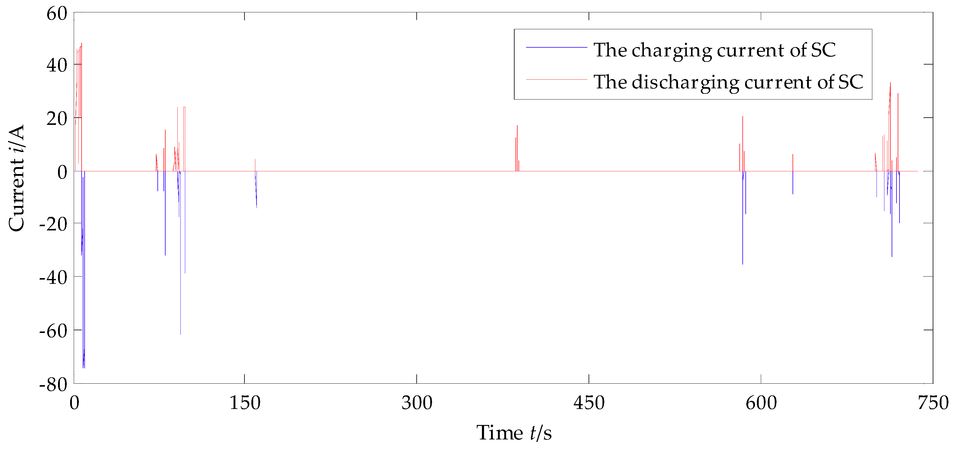
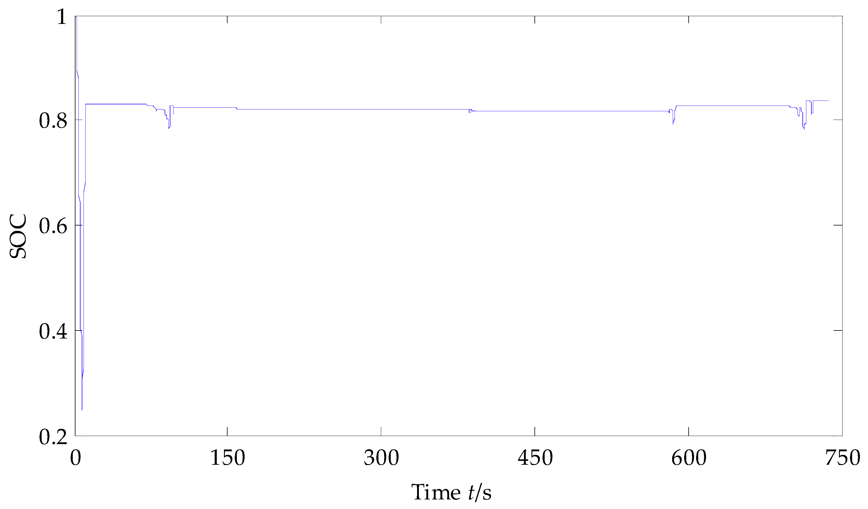
6. The Verification of Energy Management Strategy

The output current of the VPS showed in Figure 10, is obtained by using the optimized rule-based energy management strategy, which clearly shows that the output current peak of the VPS is effectively reduced, from more than 140 A to 93.6 A. The comparison between the required current of EPS and the optimized output current of VPS is shown in Figure 11, which shows that the optimized rule-based energy management strategy significantly decreases the output current of the VPS and reduces the fluctuations of output current of the VPS under the whole test condition. The detailed comparison results of the VPS output current in different stages between before and after the application of the optimized rule-based energy management strategy under the test condition is shown in Figure 12. Obviously, the optimized output current of VPS has smaller peak (93.6 A) and more plateaus, which means the fluctuations are reduced by the proposed optimized rule-based energy management strategy and the ‘peak clipping and valley filling’ effect of SC is reflected.
The charging and discharging current of the super capacitor are shown in Figure 13. Compared with Figure 11, it can be found that when the required current of EPS is higher than 93.6 A, the output current of the vehicle power supply is 93.6 A, and the lacking current is provided by the super capacitor, which acts the ‘peak clipping’ effect of SC; when the required current of EPS is lower than 74.7 A, the SOC of SC is checked to decide whether it needs to be charged. If necessary, the output current of the VPS is adjusted to 74.7 A, which not only meets the needs of the EPS, but also supplies power to the SC. In this way, the ‘valley filling’ effect of SC is exerted and the output current of the VPS is more stable. It can be seen from Figure 13 obviously, the charging current of SC is higher than the discharging current, which ensures that the SOC of SC keeps high and stable so that the SC has better current peak absorption especially when the required current of EPS is high. The SOC trend of SC is shown in Figure 14.
The comparison results show that the proposed rule-based energy management strategy can meet the current requirements of EPS in the heavy-duty vehicles, and significantly reduce the output current peak of the VPS from more than 140 A to 93.6 A and effectively depress the output current fluctuation of the VPS.

7. Conclusions

A new EPS system with hybrid power supply is constructed and the working characteristics of the hybrid power system are analyzed. The optimized rule-based energy management strategy of HP-EPS is proposed by combining the rule-based energy management strategy and the optimized energy management strategy. The rules in the energy management are optimized used the PSO algorithm which is beneficial to the proper power distribution of the VPS and SC. The comparison of the output current of the VPS used the energy management and the required current of EPS shows that the output current peak of the VPS reduces by 33% and the fluctuation of VPS output current is depressed significantly. The designed energy management strategy ensures the SOC of keep high (more than 0.8) by timely and fast charging SC, which is beneficial to absorb high current and plays the role of reducing peak and filling valley. Furthermore, this study provides a new scheme to promote the application of EPS for heavy-duty vehicles, and improves the handing stability and high speeds security of heavy-duty vehicles. The far-reaching influence is the improvement of the electrification in heavy-duty vehicles and new solutions to solve short-term power shortage.

Author Contributions

Conceptualization, B.T.; methodology, B.T. and D.Z.; software, D.Z. and Y.H.; validation, B.T., D.Z. and Y.H.; investigation, B.T., D.Z. and Y.H.; resources, H.J.; data curation, D.Z.; writing—original draft preparation, B.T. and D.Z.; writing—review and editing, B.T. and D.Z.; supervision, H.J.; project administration, B.T.; funding acquisition, B.T. All authors have read and agreed to the published version of the manuscript.

Funding

This work is financially supported by National Natural Science Foundation of China (No. 51605199), Natural Science Foundation of Jiangsu Province (No. BK20160527), Six Talent Peaks Project of Jiangsu Province (No. 2019-GDZB-084), Special fund for the transformation of scientific and technological achievements in Taizhou (No. SCG201904).

Conflicts of Interest

The authors declare no conflict of interest.

References

  1. Dannöhl, C.; Müller, S.; Ulbrich, H. H∞-control of a rack-assisted electric power steering system. Veh. Syst. Dyn. 2012, 50, 527–544. [Google Scholar] [CrossRef]
  2. Shi, G.; Lin, Y.; Zhang, X. Power Steering Technology and Development. Trans. Chin. Soc. Agric. Mach. 2006, 10, 173–176. [Google Scholar]
  3. Nakayama, T.; Suda, E. The present and future of electric power steering. Int. J. Veh. Des. 1994, 15, 243–254. [Google Scholar]
  4. Zhao, W.; Luan, Z.; Wang, C. Parametric optimization of novel electric—Hydraulic hybrid steering system based on a shuffled particle swarm optimization algorithm. J. Clean. Prod. 2018, 186, 865–876. [Google Scholar]
  5. Zhao, W.; Luan, Z.; Wang, C. Parameter optimization design of vehicle E-HHPS system based on an improved MOPSO algorithm. Adv. Eng. Softw. 2018, 123, 51–61. [Google Scholar] [CrossRef]
  6. Cao, D.; Tang, B.; Jiang, H.; Yin, C.; Zhang, D.; Huang, Y. Study on Low-Speed Steering Resistance Torque of Vehicles Considering Friction between Tire and Pavement. Appl. Sci. 2019, 9, 1015. [Google Scholar] [CrossRef] [Green Version]
  7. Mustafa, F.; Osama, M.A. Event-Based Protection Scheme for a Multiterminal Hybrid DC Power System. IEEE Trans. Smart Grid 2015, 6, 1658–1669. [Google Scholar]
  8. Teymourfar, R.; Asaei, B.; Iman-Eini, H. Stationary super-capacitor energy storage system to save regenerative braking energy in a metro line. Energy Convers. Manag. 2012, 56, 206–214. [Google Scholar] [CrossRef]
  9. Liu, Y.; Zhu, Y.; Lin, Z.; Zhao, K.; Ye, J. Energy Management Strategy Optimization of Hybrid Storage System Based on Radau Pseudo-Spectral Method. Automot. Eng. 2019, 41, 625–633. [Google Scholar]
  10. Trovão, J.P.; Antunes, C.H. A comparative analysis of meta-heuristic methods for power management of a dual energy storage system for electric vehicles. Energy Convers. Manag. 2015, 95, 281–296. [Google Scholar]
  11. Pan, C.; Chen, L.; Chen, L.; Huang, C.; Xie, M. Research on energy management of dual energy storage system based on the simulation of urban driving schedules. Int. J. Electr. Power Energy Syst. 2013, 44, 37–42. [Google Scholar] [CrossRef]
  12. Battistelli, L.; Fantauzzi, M.; Iannuzzi, D.; Lauria, D. Energy management of electrified mass transit systems with energy storage devices. In Proceedings of the International Symposium on Power Electronics Power Electronics, Electrical Drives, Automation and Motion, Sorrento, Italy, 20–22 June 2012; pp. 1172–1177. [Google Scholar]
  13. Zhang, L.; Hu, X.; Wang, Z.; Sun, F.; Deng, J.; Dorrell, D.G. Multi objective optimal sizing of hybrid energy storage system for electric vehicles. IEEE Trans. Veh. Technol. 2017, 67, 1027–1035. [Google Scholar] [CrossRef]
  14. Song, Z.; Li, J.; Han, X.; Xu, L.; Lu, L.; Ouyang, M.; Hofmann, H. Multi-objective optimization of a semi-active battery/super capacitor energy storage system for electric vehicles. Appl. Energy 2014, 135, 212–224. [Google Scholar] [CrossRef]
  15. Song, C.; Zhou, F.; Xiao, F. Parameter Matching of On-board Hybrid Energy Storage System Based on Convex Optimization Method. Mech. Eng. 2017, 53, 44–51. [Google Scholar] [CrossRef]
  16. Zhu, X.; Han, H.; Gao, S.; Shi, Q.; Cui, H.; Zu, G. A multi-stage optimization approach for active distribution network scheduling considering coordinated electrical vehicle charging strategy. IEEE Access 2018, 6, 50117–50130. [Google Scholar] [CrossRef]
  17. Santucci, A.; Sorniotti, A.; Lekakou, C. Power split strategies for hybrid energy storage systems for vehicular applications. J. Power Sources 2014, 258, 395–407. [Google Scholar] [CrossRef] [Green Version]
  18. Zhou, F.; Xiao, F.; Chang, C.; Shao, Y.; Song, C. Adaptive model predictive control-based energy management for semi-active hybrid energy storage systems on electric vehicles. Energies 2017, 10, 1063. [Google Scholar] [CrossRef] [Green Version]
  19. Song, Z.; Hofmann, H.; Li, J.; Han, X.; Ouyang, M. Optimization for a hybrid energy storage system in electric vehicles using dynamic programing approach. Appl. Energy 2015, 139, 151–162. [Google Scholar] [CrossRef]
  20. Song, C.; Zhou, F.; Xiao, F. Energy management optimization of hybrid energy storage system(HESS)based on dynamic programming. Jilin Univ. (Eng. Technol. Ed.) 2017, 47, 8–14. [Google Scholar]
  21. Zhang, S.; Xiong, R.; Cao, J. Battery durability and longevity based power management for plug-in hybrid electric vehicle with hybrid energy storage system. Appl. Energy 2016, 179, 316–328. [Google Scholar] [CrossRef]
  22. He, H.; Xiong, R.; Zhao, K.; Liu, Z. Energy management strategy research on a hybrid power system by hardware-in-loop experiments. Appl. Energy 2013, 112, 1311–1317. [Google Scholar] [CrossRef]
  23. Hou, Y.; Hu, Y.; Hu, D.; Li, C. Synthesis of Muti-Axle Steering System of Heavy Duty Vehicle Based on Probability of Steering Angle; SAE Technical Paper; SAE International: Warrendale, PA, USA, 2000. [Google Scholar] [CrossRef]
  24. Yang, H. Estimation of supercapacitor charge capacity bounds considering charge redistribution. Ieee Trans. Power Electron. 2017, 33, 6980–6993. [Google Scholar] [CrossRef] [PubMed]
  25. Bonyadi, M.R.; Michalewicz, Z. Particle Swarm Optimization for Single Objective Continuous Space Problems: A Review. Evol. Comput. 2017, 25, 1–54. [Google Scholar] [CrossRef] [PubMed]
  26. Ning, C. Study on Control Strategy of Electric Power Steering System of Large-Size Electric Bus. Master’s Thesis, Wuhan University of Technology, Wuhan, China, 2012. [Google Scholar]
Figure 1. The schematic of the EPS with hybrid power supply (HP-EPS) system.
Energies 13 00428 g001
Figure 2. The schematic of dynamic model.
Energies 13 00428 g002
Figure 3. The fitness model of energy management strategy optimization.
Energies 13 00428 g003
Figure 4. The designed test routes.
Energies 13 00428 g004
Figure 5. The test vehicle and experimental apparatus: (a) MSW DTI sensor universal measurement steering wheel; (b) the test vehicle and the installation position of experimental apparatus; (c) Correvit S-Motion DTI Non-contact optical sensor.
Energies 13 00428 g005
Figure 6. The collected signals in the test: (a) vehicle speed; (b) steering wheel torque.
Energies 13 00428 g006
Figure 7. The assist characteristic model of EPS.
Energies 13 00428 g007
Figure 8. The required current of EPS under the test conditions.
Energies 13 00428 g008
Figure 9. The fitness curve of particle swarm optimization (PSO).
Energies 13 00428 g009
Figure 10. The optimized output current of vehicle power supply.
Energies 13 00428 g010
Figure 11. The comparison between the required current of EPS and the optimized output current of vehicle power supply (VPS).
Energies 13 00428 g011
Figure 12. The detailed comparison results of the VPS output current between before and after optimization: (a) the comparison from 0 to 10 s; (b) the comparison from 80 to 100 s; (c) the comparison from 385 to 390 s; (d) the comparison from 580 to 590 s; (e) the comparison from 700 to 725 s.
Energies 13 00428 g012aEnergies 13 00428 g012b
Figure 13. The charging and discharging current of SC.
Energies 13 00428 g013
Figure 14. The state of charge (SOC) trend of the super capacitor (SC).
Energies 13 00428 g014
Table 1. The rule-based energy management strategy of HP-EPS.
Required Currentof EPSSOC of SCCurrent Distribution ofthe VPS and the SC
0 < I r e q I l o w S O C < S O C t o p
S O C S O C t o p
I g = I l o w ,   I s c D = 0 ,   I s c C = I l o w I r e q
I g = I r e q , I s c D = 0 , I s c C = 0
I l o w < I r e q I h i g h S O C > S O C b o t
S O C S O C b o t
I g = I l o w , I s c D = I r e q I g , I s c C = 0
I g = I h i g h , I s c D = 0 , I s c C = I h i g h I r e q
I r e q > I h i g h S O C > S O C b o t
S O C S O C b o t
I g = I h i g h , I s c D = I r e q I g , I s c C = 0
I g = I r e q , I s c D = 0 , I s c C = 0
Table 2. Detailed information on the main apparatuses.
ApparatusApplicationTypeManufacturer
MSW DTI sensor universal measurement steering wheelUniversal measurement steering wheel for measurement of the steering torque, steering angle, and steering speed; for vehicle driving dynamics tests like ISO 4138, steady-state circular course drive
Angle resolution: 0.5°
Torque resolution: 0.1 N·m
5612AKISTLER
Correvit S-Motion DTI
Non-contact optical sensor
High-precision, slip-free measurement of:
  • Distance;
  • Speed (x,y);
  • Acceleration and angular rates;
  • GPS position data and time;
  • Pitch and roll angle.
  • Speed resolution: 0.2 km/h
2055AKISTLER
Table 3. The required current of EPS at different vehicle speeds.
Vehicle Speed (km/h)Steering Resistance Torque (N·m)Drivers’ Preferred Steering Torque (N·m)Required Current of EPS (A)
0230.86135.6
10133.86.276.9
20109.46.861.7
4068.17.536.8
6047.08.123.8
8041.58.520.2
10038.8918.3

