Serial Switch Only Rectifier as a Power Conditioning Circuit for Electric Field Energy Harvesting


Abstract
:
1. Introduction
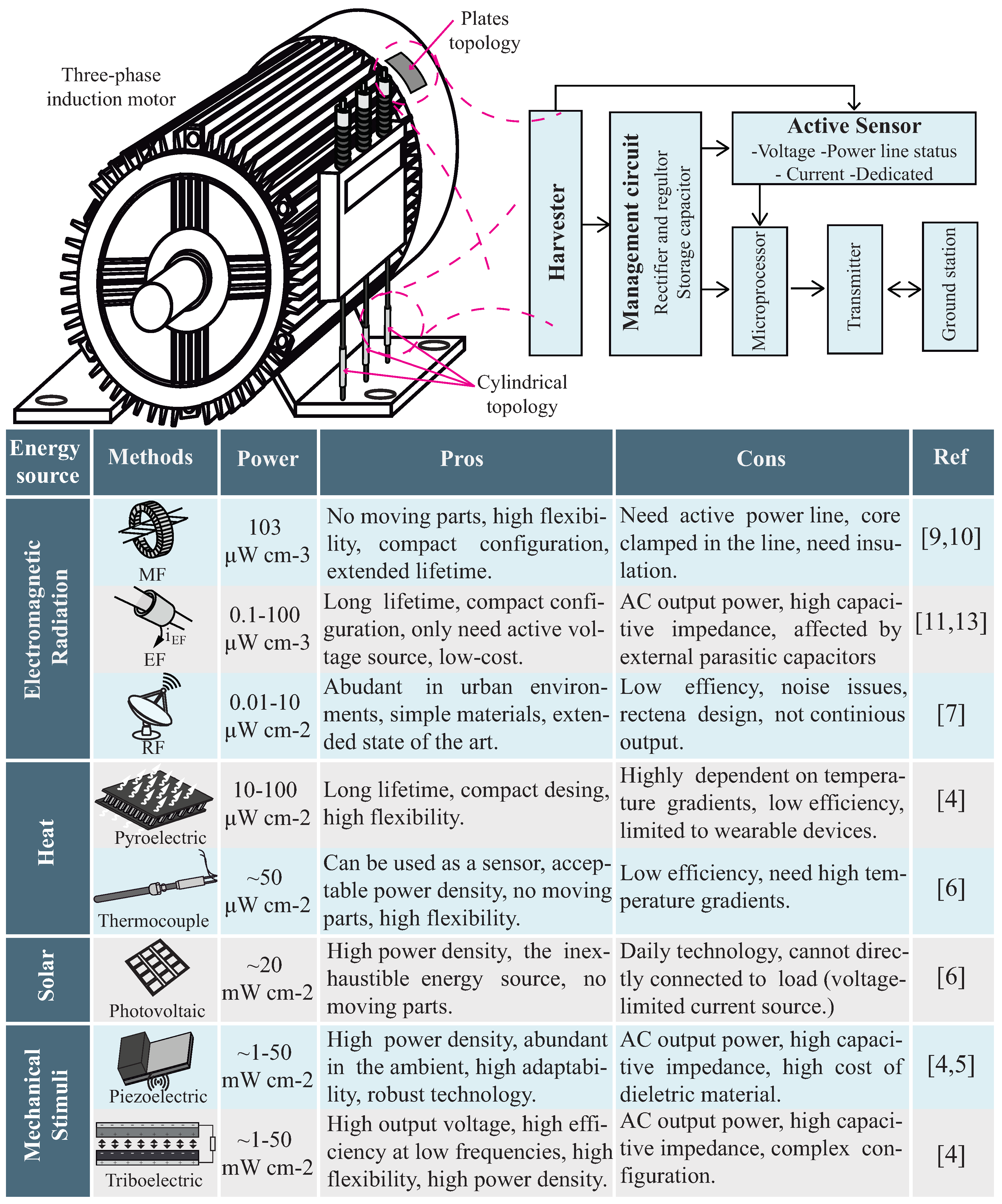
2. Material and Methods
2.1. Management Circuits
2.1.1. Voltage Doubler
2.1.2. Full Bridge Rectifier
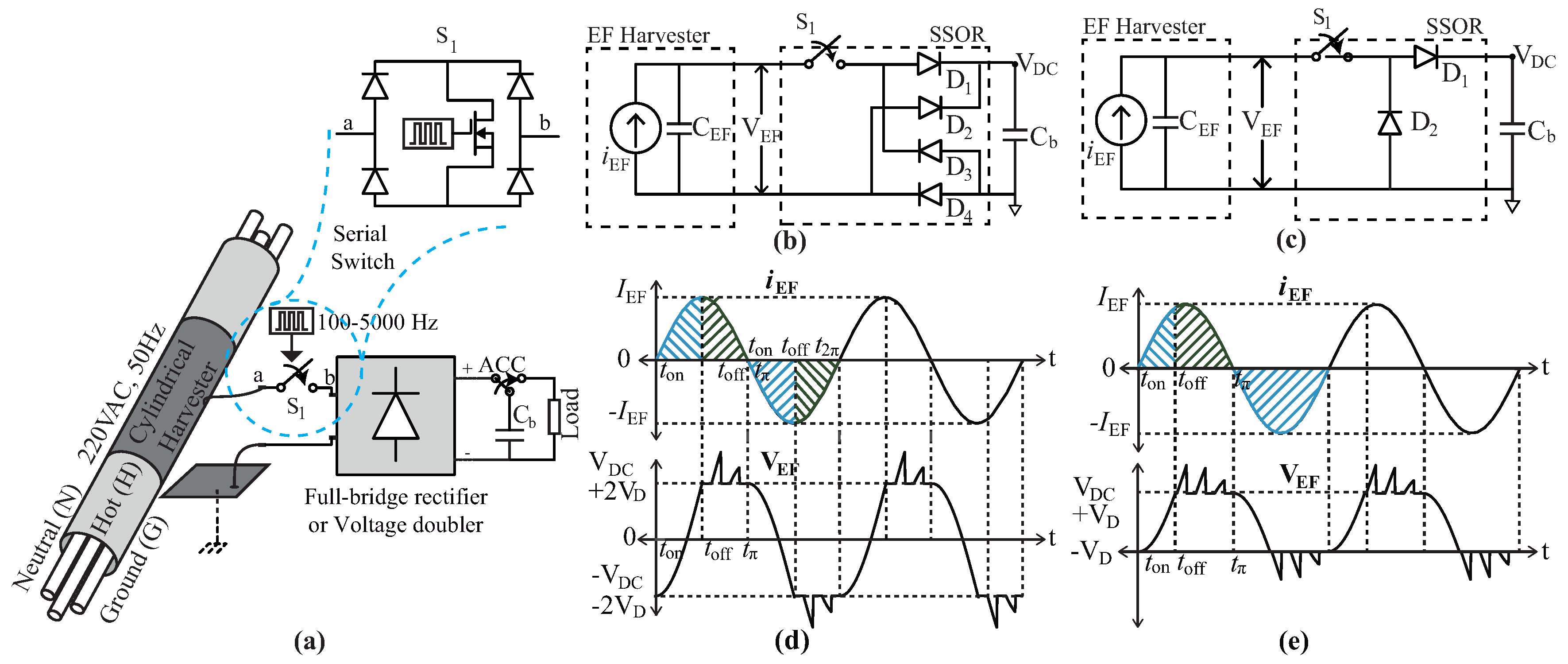
3. Serial Switch-Only Rectifier
4. Results
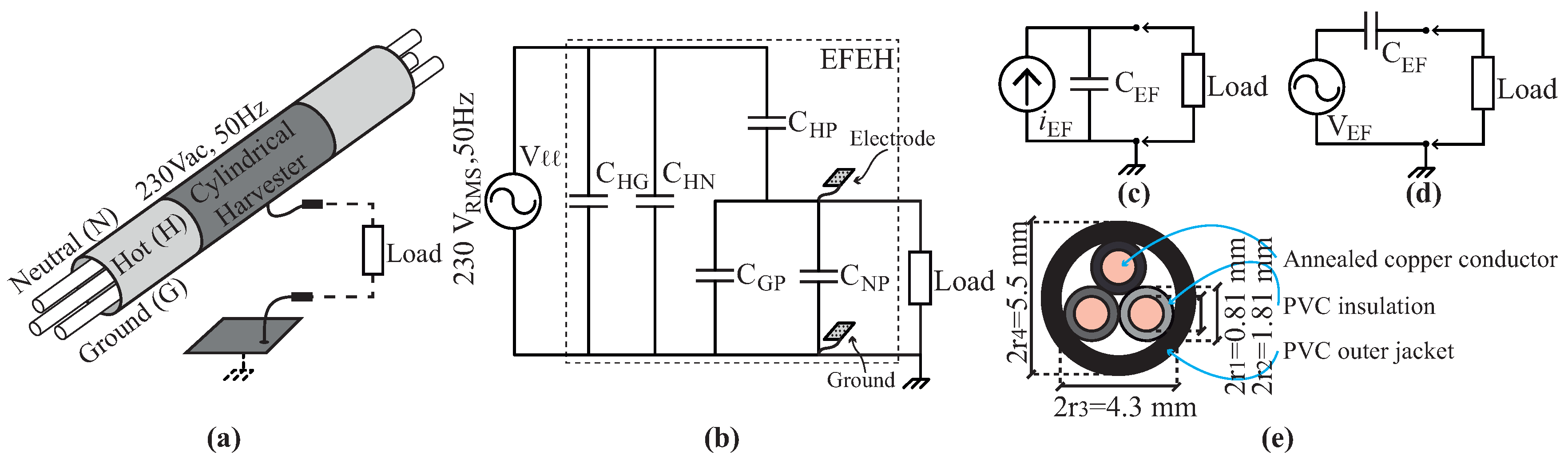
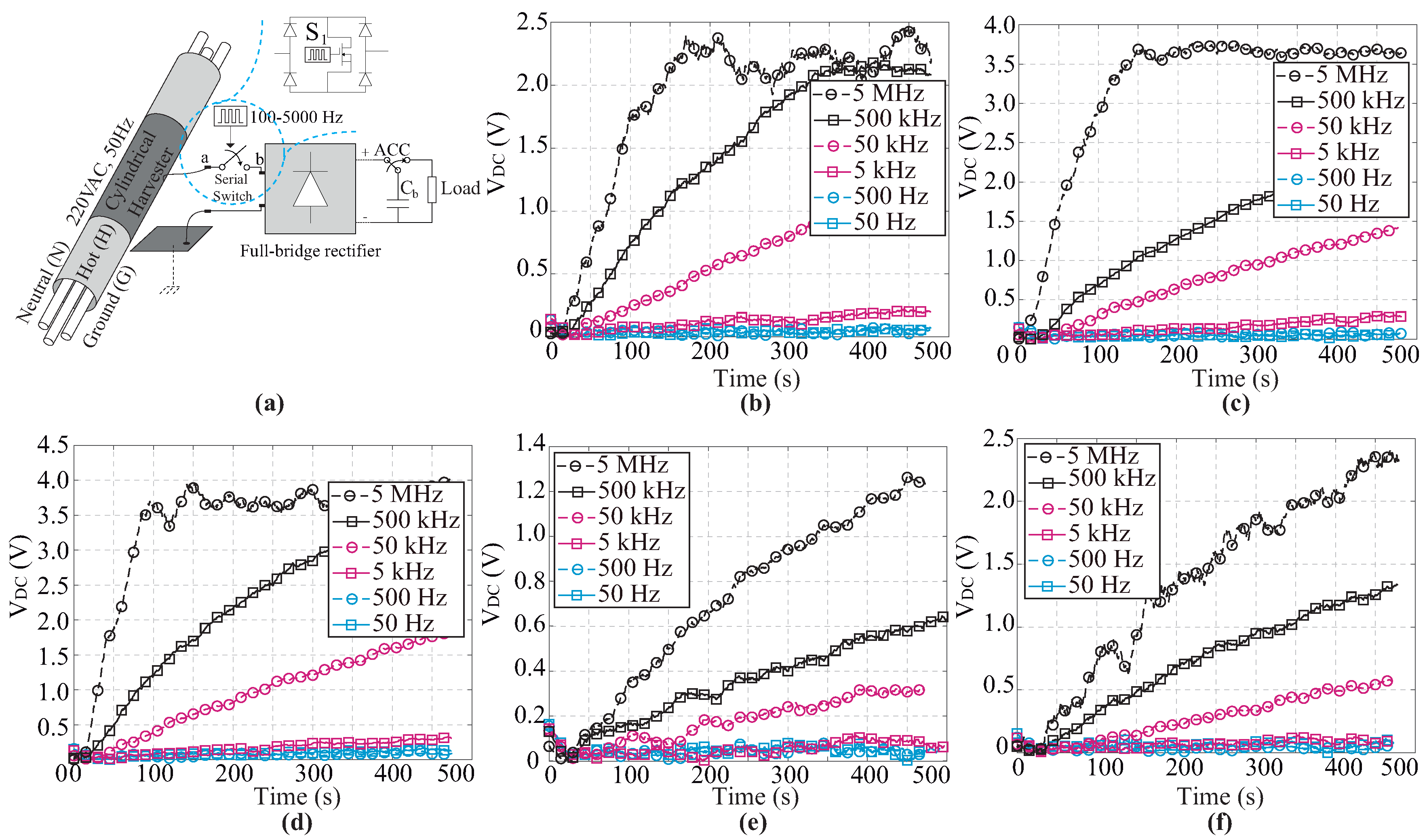
- The device deployed in real applications consists of an aluminum tube (different length) mounted on three-core electrical wire. Electrical wire is a flexible mains cable with three 0.5 mm2 solid copper conductors. The mains supply is between 220 and 240 V (50 Hz).
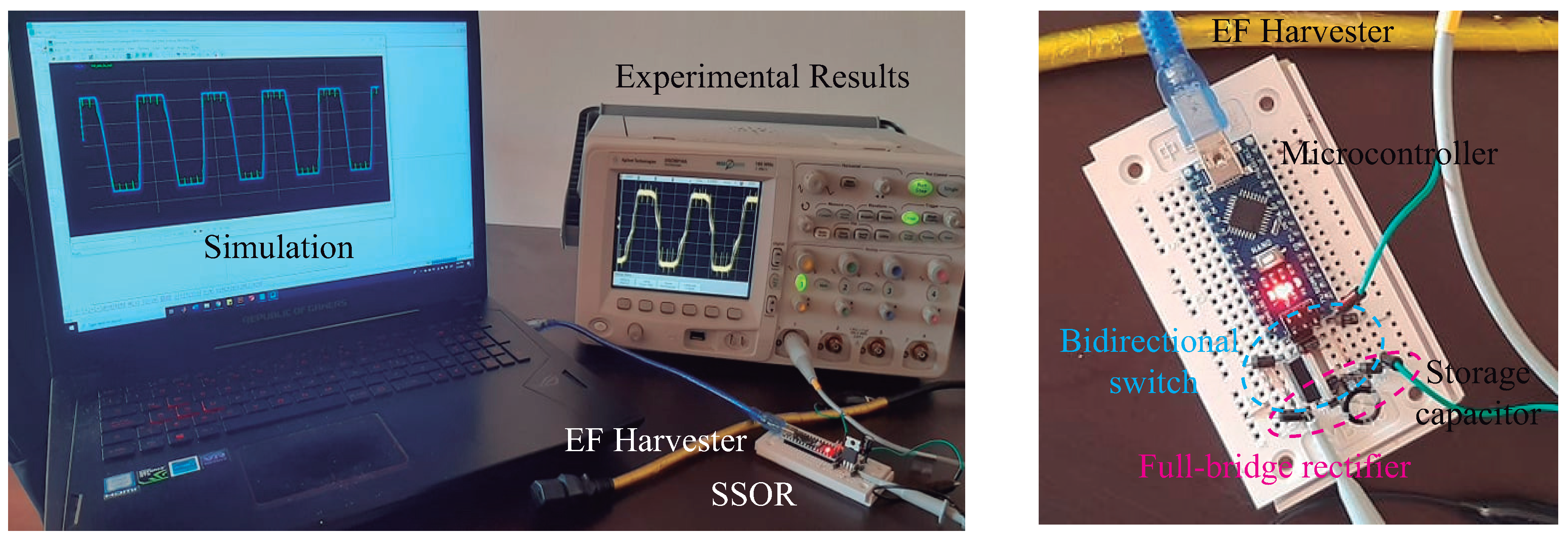
- Both harvester’s terminals are connected to SSOR circuit. We select a diode 1n4007 as a switch. is 0.7 V, and the typical junction capacitance is in order of pico-farads (2.5 pF at 100 V and 30 pF at 0.7 V). The gathered energy is stored in a 100 F capacitor.
- Bidirectional switch topology is a diode embedded MOSFET consisting of a full-bridge rectifier (1n4007 diodes) connected in parallel with a IRF840-MOSFET. This circuit requires only one active element that reduces the number of external sources to energize drivers. In addition, the switching control is easy because it is only needed to generate a simple PWM signal.
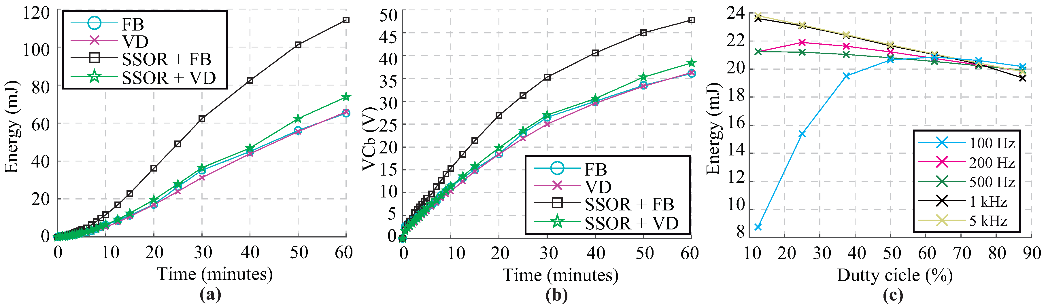
- An Arduino Nano generates the PWM signal (duty cycle fixed 50%). Switching frequency is defined between 100 Hz to 5 kHz. For the sake of this work, the controller is powered using external sources. The controller works in ultra-low power mode to reduce power consumption.
- Despite the fact that this work uses external sources, the device can be replaced with nanoelectromechanical systems (NEMS), in which consumption is less than 1 nJ per cycle [30]. On the other hand, the controller can be replaced with ultra-low power microcontroller, type STM32L4 [31], in which consumption is less than 1.5 mJ.
- As shown in Figure 4a, an autonomous connection circuit (ACC) is used to commute between charging and load connection modes. To this end, an IRF-840 MOSFET is selected. Similar to Arduino energizing, the transistor is externally powered. Arduino Nano controls the opening and closing of ACC.
- The proposed approach was simulated using the PSIM software and linking this with MATLAB 2020a.
4.1. SSOR Performance
4.2. Frequency Analysis
5. Discussion
6. Conclusions
Author Contributions
Funding
Conflicts of Interest
References
- Gungor, V.C.; Sahin, D.; Kocak, T.; Ergut, S.; Buccella, C.; Cecati, C.; Hancke, G.P. A Survey on Smart Grid Potential Applications and Communication Requirements. IEEE Trans. Ind. Inform. 2013, 9, 28–42. [Google Scholar] [CrossRef] [Green Version]
- Lu, N.; Cheng, N.; Zhang, N.; Shen, X.; Mark, J.W. Connected Vehicles: Solutions and Challenges. IEEE Internet Things J. 2014, 1, 289–299. [Google Scholar] [CrossRef]
- Sudevalayam, S.; Kulkarni, P. Energy Harvesting Sensor Nodes: Survey and Implications. IEEE Commun. Surv. Tutor. 2011, 13, 443–461. [Google Scholar] [CrossRef] [Green Version]
- Wang, Z.L. On Maxwell’s displacement current for energy and sensors: The origin of nanogenerators. Mater. Today 2017, 20, 74–82. [Google Scholar] [CrossRef]
- Abasian, A.; Tabesh, A.; Rezaei-Hosseinabadi, N.; Nezhad, A.Z.; Bongiorno, M.; Khajehoddin, S.A. Vacuum-Packaged Piezoelectric Energy Harvester for Powering Smart Grid Monitoring Devices. IEEE Trans. Ind. Electron. 2019, 66, 4447–4456. [Google Scholar] [CrossRef]
- Akan, O.B.; Cetinkaya, O.; Koca, C.; Ozger, M. Internet of Hybrid Energy Harvesting Things. IEEE Internet Things J. 2018, 5, 736–746. [Google Scholar] [CrossRef]
- Lu, X.; Wang, P.; Niyato, D.; Kim, D.I.; Han, Z. Wireless Networks with RF Energy Harvesting: A Contemporary Survey. IEEE Commun. Surv. Tutor. 2015, 17, 757–789. [Google Scholar] [CrossRef] [Green Version]
- Moghe, R.; Iyer, A.R.; Lambert, F.C.; Divan, D.M. A Low-Cost Wireless Voltage Sensor for Monitoring MV/HV Utility Assets. IEEE Trans. Smart Grid 2014, 5, 2002–2009. [Google Scholar] [CrossRef]
- Hosseinimehr, T.; Tabesh, A. Magnetic Field Energy Harvesting from AC Lines for Powering Wireless Sensor Nodes in Smart Grids. IEEE Trans. Ind. Electron. 2016, 63, 4947–4954. [Google Scholar] [CrossRef]
- Yuan, S.; Huang, Y.; Zhou, J.; Xu, Q.; Song, C.; Thompson, P. Magnetic Field Energy Harvesting under Overhead Power Lines. IEEE Trans. Power Electron. 2015, 30, 6191–6202. [Google Scholar] [CrossRef] [Green Version]
- Cetinkaya, O.; Akan, O.B. Electric-Field Energy Harvesting in Wireless Networks. IEEE Wirel. Commun. 2017, 24, 34–41. [Google Scholar] [CrossRef]
- Zangl, H.; Bretterklieber, T.; Brasseur, G. A Feasibility Study on Autonomous Online Condition Monitoring of High-Voltage Overhead Power Lines. IEEE Trans. Instrum. Meas. 2009, 58, 1789–1796. [Google Scholar] [CrossRef]
- Moghe, R.; Yang, Y.; Lambert, F.; Divan, D. A scoping study of electric and magnetic field energy harvesting for wireless sensor networks in power system applications. In Proceedings of the 2009 IEEE Energy Conversion Congress and Exposition, San Jose, CA, USA, 20–24 September 2009; pp. 3550–3557. [Google Scholar] [CrossRef]
- Guo, F.; Hayat, H.; Wang, J. Energy harvesting devices for high voltage transmission line monitoring. In Proceedings of the 2011 IEEE Power and Energy Society General Meeting, Detroit, MI, USA, 24–29 July 2011; pp. 1–8. [Google Scholar] [CrossRef]
- Moser, M.J.; Bretterklieber, T.; Zangl, H.; Brasseur, G. Strong and Weak Electric Field Interfering: Capacitive Icing Detection and Capacitive Energy Harvesting on a 220-kV High-Voltage Overhead Power Line. IEEE Trans. Ind. Electron. 2011, 58, 2597–2604. [Google Scholar] [CrossRef]
- Kim, H.; Choi, D.; Gong, S.; Park, K. Stray electric field energy harvesting technology using MEMS switch from insulated AC power line. Electron. Lett. 2014, 50, 1236–1238. [Google Scholar] [CrossRef]
- Menéndez, O.; Kouro, S.; Pérez, M.; Cheein, F.A. Mechatronized maximum power point tracking for electric field energy harvesting sensor. AEU Int. J. Electron. Commun. 2019, 110, 152830. [Google Scholar] [CrossRef]
- Kang, S.; Kim, J.; Yang, S.; Yun, T.; Kim, H. Electric field energy harvesting under actual three-phase 765 kV power transmission lines for wireless sensor node. Electron. Lett. 2017, 53, 1135–1136. [Google Scholar] [CrossRef]
- Kang, S.; Yang, S.; Kim, H. Non-intrusive voltage measurement of ac power lines for smart grid system based on electric field energy harvesting. Electron. Lett. 2017, 53, 181–183. [Google Scholar] [CrossRef]
- Chang, K.; Kang, S.; Park, K.; Shin, S.; Kim, H.S.; Kim, H. Electric Field Energy Harvesting Powered Wireless Sensors for Smart Grid. J. Electr. Eng. Technol. 2012, 7, 75–80. [Google Scholar] [CrossRef] [Green Version]
- Jain, P.; Pahlevaninezhad, M.; Pan, S.; Drobnik, J. A Review of High-Frequency Power Distribution Systems: For Space, Telecommunication, and Computer Applications. IEEE Trans. Power Electron. 2014, 29, 3852–3863. [Google Scholar] [CrossRef]
- Guevara, L.; Auat Cheein, F. The Role of 5G Technologies: Challenges in Smart Cities and Intelligent Transportation Systems. Sustainability 2020, 12, 6469. [Google Scholar] [CrossRef]
- Fong, Y.C.; Raman, S.R.; Ye, Y.; Cheng, K.W.E. Generalized Topology of a Hybrid Switched- Capacitor Multilevel Inverter for High- Frequency AC Power Distribution. IEEE J. Emerg. Sel. Top. Power Electron. 2020, 8, 2886–2897. [Google Scholar] [CrossRef]
- Raman, S.R.; Fong, Y.C.; Ye, Y.; Eric Cheng, K.W. Family of Multiport Switched-Capacitor Multilevel Inverters for High-Frequency AC Power Distribution. IEEE Trans. Power Electron. 2019, 34, 4407–4422. [Google Scholar] [CrossRef]
- Raman, S.R.; Ye, Y.; Cheng, K.W.E. Switched-capacitor multilevel inverters for high frequency AC microgrids. In Proceedings of the 2017 IEEE Applied Power Electronics Conference and Exposition (APEC), Tampa, FL, USA, 26–30 March 2017; pp. 2559–2564. [Google Scholar]
- International Electrotechnical Commission. IEC Standard Voltages IEC 60038; International Electrotechnical Commission: Geneva, Switzerland, 2009. [Google Scholar]
- Rodríguez, J.C.; Holmes, D.G.; McGrath, B.P.; Wilkinson, R.H. Maximum energy harvesting from medium voltage electric-field energy using power line insulators. In Proceedings of the 2014 Australasian Universities Power Engineering Conference (AUPEC), Perth, Australia, 28 September–1 October 2014; pp. 1–6. [Google Scholar] [CrossRef]
- Rodríguez, J.C.; Holmes, D.G.; Mcgrath, B.; Wilkinson, R.H. A Self-Triggered Pulsed-Mode Flyback Converter for Electric-Field Energy Harvesting. IEEE J. Emerg. Sel. Top. Power Electron. 2018, 6, 377–386. [Google Scholar] [CrossRef]
- Zhang, J.; Li, P.; Wen, Y.; Zhang, F.; Yang, C. A Management Circuit with Upconversion Oscillation Technology for Electric-Field Energy Harvesting. IEEE Trans. Power Electron. 2016, 31, 5515–5523. [Google Scholar] [CrossRef]
- Zhu, J.; Liu, X.; Shi, Q.; He, T.; Sun, Z.; Guo, X.; Liu, W.; Sulaiman, O.B.; Dong, B.; Lee, C. Development Trends and Perspectives of Future Sensors and MEMS NEMS. Micromachines 2020, 11, 7. [Google Scholar] [CrossRef] [Green Version]
- STMicroelectronics. STM32L4 Series. 2020. Available online: https://www.st.com/ (accessed on 18 September 2020).
- Cetinkaya, O.; Akan, O.B. Electric-Field Energy Harvesting From Lighting Elements for Battery-Less Internet of Things. IEEE Access 2017, 5, 7423–7434. [Google Scholar] [CrossRef]
- Yan, D.; Li, J.; Zhang, J.; Tian, X.; Ou, D.; Gu, J. A capacitive electric-field energy harvester with double-layer copper foil for 220V power line. J. Phys. Conf. Ser. 2020, 1585, 012002. [Google Scholar] [CrossRef]
- Honda, M.; Sakurai, T.; Takamiya, M. Wireless temperature and illuminance sensor nodes with energy harvesting from insulating cover of power cords for building energy management system. In Proceedings of the 2015 IEEE PES Asia-Pacific Power and Energy Engineering Conference (APPEEC), Brisbane, Australia, 15–18 November 2015; pp. 1–5. [Google Scholar]
- Moghe, R.; Iyer, A.R.; Lambert, F.C.; Divan, D. A Low-Cost Electric Field Energy Harvester for an MV/HV Asset-Monitoring Smart Sensor. IEEE Trans. Ind. Appl. 2015, 51, 1828–1836. [Google Scholar] [CrossRef]
- AsahiKASEI. Ultra Low Power Voltage Detector. 2020. Available online: https://www.microchip.com (accessed on 2 September 2020).
- TexasInstruments. SimpleLink™ 32-bit Arm Cortex-M3 Sub 1 GHz wireless MCU with 128kB Flash. 2020. Available online: https://www.ti.com/product/CC1310 (accessed on 2 September 2020).
- Zanella, A.; Bui, N.; Castellani, A.; Vangelista, L.; Zorzi, M. Internet of Things for Smart Cities. IEEE Internet Things J. 2014, 1, 22–32. [Google Scholar] [CrossRef]


| Component | Part Number | Circuit Parameters | |
|---|---|---|---|
| Full bridge rectifier | 1n4007 | Forward voltage: DC blocking voltage: Peak reverse current: | = 1 V = 1000 V = 10 A |
| Cylindrical shell Harvester | - | Length: Thickness: Material: | 10 cm, 1 m, 10 m 0.1 mm Aluminum |
| Microcontroller | Arduino Nano | Operating Voltage: DC Current on I/O Pins: PWM: Sleep mode: Microcontroller: | 5 V 40 mA Pins 3, 5, 6, 9, 11 0.7 A ATmega328P |
| MOSFET Serial switch | IRF840 | Input Capacitance: Output Capacitance: Reverse Transfer Capacitance: | 1300 pF 310 pF 120 pF |
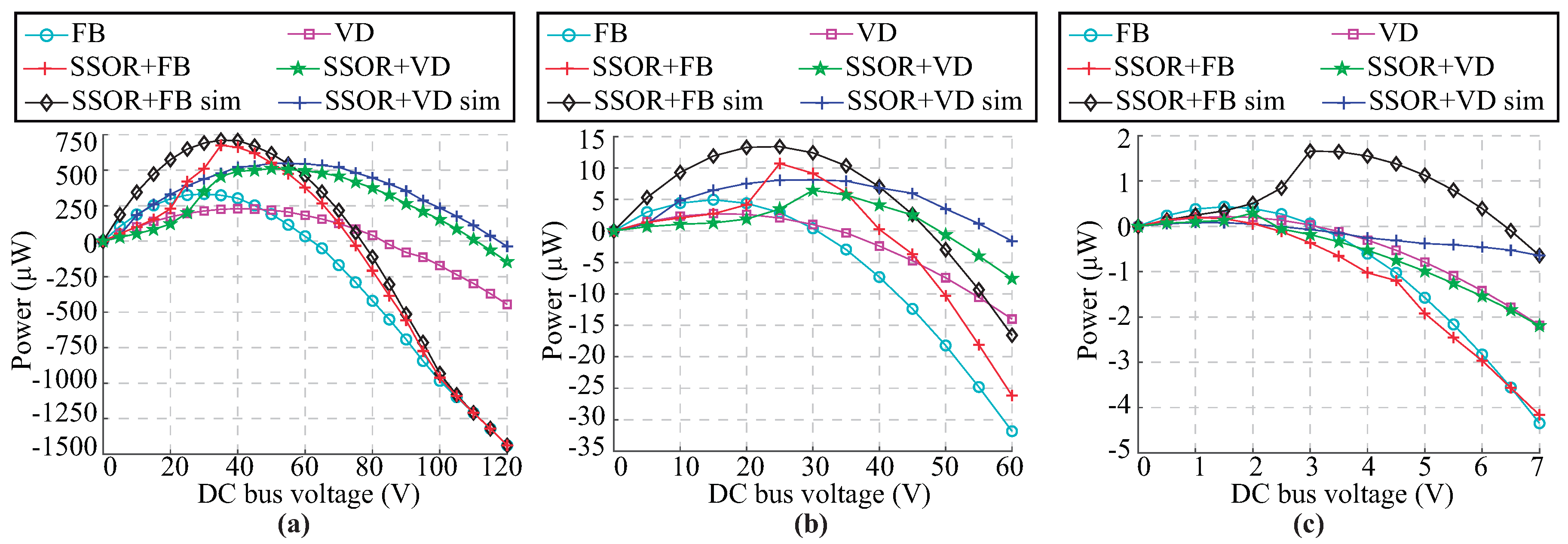
| Management Circuit | Harvester’s Length | FB | VD | SSOR + FB | SSOR + VD |
|---|---|---|---|---|---|
| Maximum power | 10 m | 332.5 W 25 V | 229.0 W 40 V | 675.5 W 35 V | 512 W 50 V |
| Maximum voltage Positive power | 10 m | 60 V | 80 V | 75 V | 110 V |
| Maximum Power | 1 m | 9.91 W 15 V | 5.47 W 15 V | 21.42 W 25 V | 12.9 W 30 V |
| Maximum voltage Positive power | 1 m | 30 V | 30 V | 40 V | 50 V |
| Maximum power | 10 cm | 8.66 W 1.5 V | 4.34 W 1.5 V | 3.95 W 1 V | 5.89 W 2 V |
| Maximum voltage Positive power | 10 cm | 3 V | 3 V | 2 V | 2.5 V |
| Management Circuit | Ref | Power/Energy | Voltage | Size | Characteristics | |
|---|---|---|---|---|---|---|
| Voltage Doubler | - Advantages: Solid-state microchip; Low energy losses related to switching states; Energy transfer: two-times per cycle - Disadvantages: Low efficiency for more massive harvesters; Leakage current diodes; Need regulating circuit Smaller harvesters | [11] | 12 mJ | 220 V | 10–60 cm | Double-layered cylindrical; capacitive load; Home automation. |
| [32] | 1.75 J | 220 V | 50 × 50 cm | Plate topology; capacitive load; lighting elements for IoT systems. | ||
| [33] | 2.47 mJ | 220 V | 20 cm | Double-layered cylindrical; resistive load; Temperature sensor | ||
| Full-bridge Rectifier | - Advantages: Only need two diodes; compact configuration; low energy losses related to switching states. - Disadvantages: Low efficiency for more massive harvester; Leakage current diodes; Need a regulating circuit Smaller harvesters | [17] | 0.6 W | 220 V | 7 × 7 × 2 cm | Floating capacitor; plate topology; resistive load WSN for Smart-Grid |
| [34] | 360 mJ | 100 V | 10–40 cm | Cylindrical havester; Temperature and Illuminance Sensor | ||
| Our work | - Advantages: Low energy losses; Greater output power - Disadvantages: Need bidirectional switch; Complex configuration. Larger Harvester | – | 120 mJ | 220 V | 10 cm 1 m 10 m | Cylindrical harvester; capacitive load; SSOR circuit; IoT devices |
© 2020 by the authors. Licensee MDPI, Basel, Switzerland. This article is an open access article distributed under the terms and conditions of the Creative Commons Attribution (CC BY) license (http://creativecommons.org/licenses/by/4.0/).
Share and Cite
Menéndez, O.; Romero, L.; Cheein, F.A. Serial Switch Only Rectifier as a Power Conditioning Circuit for Electric Field Energy Harvesting. Energies 2020, 13, 5279. https://doi.org/10.3390/en13205279
Menéndez O, Romero L, Cheein FA. Serial Switch Only Rectifier as a Power Conditioning Circuit for Electric Field Energy Harvesting. Energies. 2020; 13(20):5279. https://doi.org/10.3390/en13205279
Chicago/Turabian StyleMenéndez, Oswaldo, Loreto Romero, and Fernando Auat Cheein. 2020. "Serial Switch Only Rectifier as a Power Conditioning Circuit for Electric Field Energy Harvesting" Energies 13, no. 20: 5279. https://doi.org/10.3390/en13205279