Technical Note

Experimental Study on Blasting Energy Distribution and Utilization Efficiency Using Water Jet Test

1
School of Civil and Resource Engineering, University of Science and Technology Beijing, Beijing 100083, China
2
State Key Laboratory for Geomechanics and Deep Underground Engineering, Beijing 100083, China
3
Institute of Mining Engineering, Guizhou Institute of Technology, Guizhou 550003, China
*
Author to whom correspondence should be addressed.
Energies 2020, 13(20), 5340; https://doi.org/10.3390/en13205340
Submission received: 2 August 2020 / Revised: 19 September 2020 / Accepted: 30 September 2020 / Published: 14 October 2020

Abstract

:
The blasting stress wave and blasting gas generated by explosive blasting are the two main motive powers of rock fragmentation. An experimental method based on water jet test is used to study the energy distribution ratio of blasting stress wave and blasting gas; the utilization efficiency of blasting energy under different borehole constraint conditions is also analyzed. It proves that the blasting stress wave does not cause the water jet, and the blasting gas is the only power of the water column jet. The results show that the energy of the blasting gas and blasting stress wave respectively account for about 64% and 36% of the total energy generated by the explosion of lead azide. The utilization efficiency of the blasting gas energy under strong, medium, and weak constraint conditions is 100%, 80%, and 52%, respectively. The borehole constraint condition is crucial for the effective utilization of blasting energy.

1. Introduction

Explosive blasting is an extremely rapid chemical energy release process that has a strong impact on the surrounding medium and produces a large amount of blasting gas [1]. In the rock blasting field (e.g., roadway excavation [2,3] and ore fragmentation [4]), the effective utilization of blasting energy and the efficient fragmentation of rock are currently the subject of a great deal of research. At present, the theory of the combined action of blasting stress wave and blasting gas [5] is more practical and accepted by most researchers because it comprehensively considers the role of blasting stress wave and blasting gas in the rock failure process. Based on this theoretical consensus, it is hoped that the energy distribution characteristics of the blasting stress wave and blasting gas and the effects on rock fragmentation can be quantitatively analyzed in order to enrich rock blasting theory. Many scholars have used some feasible methods to study this [6,7,8,9], which has played a positive role in the understanding and development of rock blasting theory.
In the study of the action effect of blasting stress waves, Banadaki et al. [9] shielded the effect of blasting gas on the rock by inserting a copper tube into the borehole, and combined experimental results with numerical simulation to study the effect of the blasting stress wave on rock damage. Yang et al. [1,10] used two-dimensional model experiments with the borehole open to shield the effect of blasting gas, and studied the effects of the blasting stress wave and blasting gas in the rock failure process. The experimental results showed that the blasting stress wave is the direct reason for the formation of the crush zone and the blasting gas is the main driving force for the formation of the fracture zone. Cho et al. [11] used a numerical simulation method to study the effect of blasting stress waves with different waveforms on crack propagation in rock. The results showed that the crack propagation is mainly affected by the rising edge of the blasting stress wave, and the higher loading rate will increase the number of radial cracks.
In the study of the action effect of blasting gas, Kutter et al. [12] explored the action characteristics of the blasting gas and proposed a “gas wedge” effect of the blasting gas. It was believed that the blasting gas can form a quasi-static stress field inside the crack of the rock medium. Wang et al. [4] produced high-pressure gas by a mechanical method and wedged it into rock fissures to simulate the destructive effect of blasting gas on the rock. The results showed that under the action of high-pressure gas, the rock exhibited quasi-static failure characteristics with tensile fracture as the main failure mode. In addition, through theoretical derivation and analysis, Yang et al. [13] believed that the microcracks near the borehole gradually propagate under the driving pressure of the blasting gas, while the cracks farther from the borehole are further propagated under the combined action of the expansion pressure of the blasting gas and the in situ stress field. Trivino et al. [14] combined the FEM and the DEM methods to optimize the blasting parameters and carried out on-site blasting experiments. The data analysis showed that the main damage of the rock in the experiment was caused by blasting gas, indicating that it is still difficult to quantify the relative contribution of the blasting stress wave and blasting gas at present.
There are still different views on the proportion of the rock fragmentation effect caused by blasting stress waves and blasting gas and their distribution in time and space [14,15,16]. In this paper, the water jet test is used to calculate the water jet velocity and kinetic energy caused by the blasting of lead azide and to further analyze the energy distribution characteristics of the blasting stress wave and blasting gas. In addition, different materials are used to block the borehole in order to study the utilization efficiency of blasting energy under different borehole constraint conditions.

2. Experimental Design

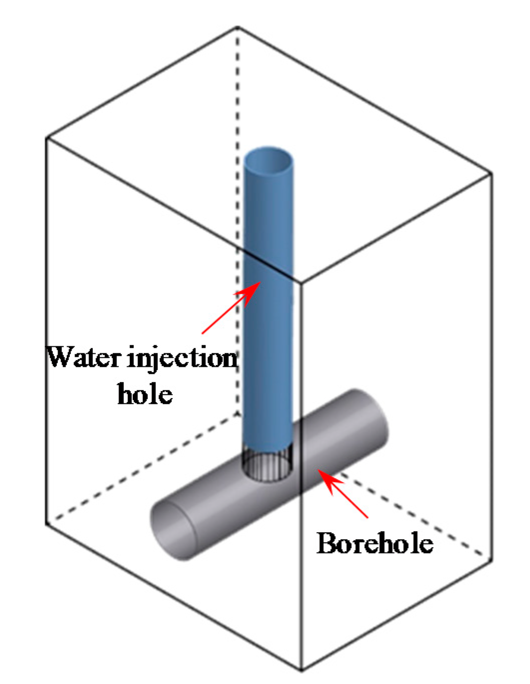
The experimental setup of the water jet test is shown in Figure 1. Using stainless steel as raw material, the experimental test specimen shown in Figure 2 was machined. The horizontal hole was the borehole, and the vertical hole was a water injection hole. The borehole and the water injection hole were connected to each other. The water column, charge condition, and borehole constraint in the test specimen are shown in Figure 3. The diameter of the water injection hole was d1 = 3 mm, the height of the water column in the hole was l = 55 mm, the mass of the water column was m = 0.39 g, and the diameter of the borehole was d2 = 4 mm. The middle part of the borehole was the charge section, and the two sides were the blocking sections. The water column and the charge section were separated by a waterproof membrane in order to prevent water in the water injection hole from being immersed in the explosive in the borehole. In this experiment, the blasting energy was restrained and controlled by the blocking sections on both sides of the explosive. There were two kinds of blocking materials in the borehole—namely, plasticine and fine sand. The main components of plasticine are calcium carbonate, liquid paraffin, and glycerin. The density of plasticine is 1.7 g/cm3. The plasticine has strong plasticity and has a weaker constraint on the blasting energy. The fine sand was solidified after being mixed with glue, and the blasting energy was strongly constrained when it was used as the blocking material.
The explosive used in the experiment was lead azide (Pb(N3)2), which was detonated by the high-voltage discharge of metal probes. According to the blocking material of the borehole, there were three experimental groups, namely: (1) both blocking materials A and B were fine sand mixed with glue, recorded as the experimental group with strong constraint; (2) blocking material A was plasticine and blocking material B was fine sand mixed with glue, recorded as the experimental group with medium constraint; (3) both blocking materials A and B were plasticine, recorded as the experimental group with weak constraint. With the charge amount as a variable, each group carried out the blasting experiments with the charge amount of C = 20, 30, 40, 50, 60, 70, and 80 mg.
After the preparation for the experiment was completed, the accent light, shown in Figure 1, was turned on, and the focus of the high-speed camera was adjusted. The high-speed camera was set to the post-trigger mode to start shooting, and then the detonating device was turned on to detonate the explosive through high-voltage discharge. Under the action of the blasting load, the water column in the water injection hole jetted out and the whole process was recorded by a high-speed camera. The recording speed of the high-speed camera was 20,000 fps, and the time interval between two successive photos was 50 μs.

3. Experiment Analysis

3.1. Phenomenon Analysis

The blasting stress wave and the blasting gas are the two main motivations for rock fragmentation in rock blasting. The experiments mainly studied the utilization characteristics of blasting energy under different blocking constraint conditions. In order to distinguish the effects of blasting stress wave and blasting gas, the verification experiment was carried out before the above three experimental groups were performed. The test specimen of the verification experiment is shown in Figure 4; the vertical water injection hole and the horizontal borehole were not connected, and there was a separation distance of 2 mm between the two holes. Since the water injection hole and the borehole were not connected, the blasting gas could not enter the water injection hole, and the blasting gas could not exert an effect on the water column. Therefore, it can be considered that the effect of the blasting gas on the water column was shielded, and the water column was only subjected to the blasting stress wave. The high-speed camera was used to photograph and record the experimental process of the verification experiment group. It was found that regardless of the charge amount or the blocking constraint, the water column in the water injection hole did not have a jet phenomenon, indicating that the blasting stress wave did not change the mechanical energy of the water column. It can be concluded that under the experimental conditions of this paper, the effect of the blasting stress wave on the water column jet was basically negligible.
On the basis of the verification experiment, three experimental groups were carried out. Under the action of the blasting load, the water column in the water injection hole was jetted. Figure 5 shows a series of photos of water jet in the water injection hole under blasting load (weak constraint, C = 20 mg). The verification experiment proved that the blasting stress wave did not contribute to the jet of the water column. Therefore, it can be considered that the water jet in the water injection hole was caused by the action of the blasting gas. When t = 100 μs, the water column began to jet out of the water injection hole; when t = 200 μs, the water column continued to jet, and the length of the jetted water column was longer. During t = 0–200 μs, the overall shape of the water column was complete, showing an overall “lifting” motion state, and the overall motion state of the water column was coordinated. In this stage, the jet velocity of the water column reached its peak and the jet process was the most stable. When t > 300 μs, the overall shape of the jetted water column changed and the jet velocity of each section of the water column was inconsistent. The middle part of the jetted water column became thinner, the upper part of the jetted water column was gradually atomized, and the motivation state of the jetted water was more complicated and variable. After the experiment, the states of the blocking materials in the test specimen were checked one by one. It was found that the blocking material of the fine sand mixed with the glue was basically non-destructive and did not flush out of the borehole. However, the blocking material of the plasticine was significantly compressed and flushed out of the borehole.

3.2. Data Analysis

The maximum jet velocity vmax of the water column was obtained by measuring the change of the height h of the jetted water column in t = 0–200 μs. The work of the blasting load on the water column is:
W = Δ E k + Δ E g + W f
where W is the work of the blasting load on the water column; ΔEk is the change of the kinetic energy of the water column, the initial kinetic energy of the water column being 0; ΔEg is the change of the gravitational potential energy of the water column; and Wf is the work of frictional resistance between the water column and the wall of the water injection hole during the jet process.
When 0.39 g of water rises by 1 cm, the gravitational potential energy of the water column increases by 3.9 × 10⁻⁵ J, which is much smaller than the increase in kinetic energy. Therefore, compared with the change of the kinetic energy ΔEk of the water column, the change of the gravitational potential energy ΔEg of the water column and the work of frictional resistance Wf can be neglected. Therefore, Equation (1) can be simplified as:
W Δ E k = 1 2 m v max 2
where m is the mass of the water column, m = 0.39 g, and vmax is the maximum jet velocity of the water column.
In the above analysis, the recording speed of the high-speed camera was extremely fast, and the maximum jet velocity of the water column can be calculated as:
v max = Δ h Δ t
where Δh is the change in the height of the jetted water column during t = 100–200 μs and Δt is the time interval, Δt = 100 μs.
According to Equations (2) and (3), the maximum jet velocity vmax and the work of blasting load W with different charge amount C under different constraint conditions, shown in Table 1, were calculated.
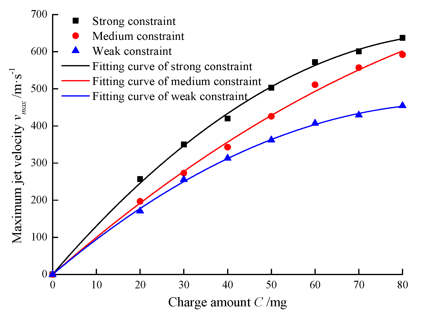
According to the data in Table 1, the relationship and the corresponding fitting curves between the charge amount C and the maximum jet velocity vmax were obtained and are shown in Figure 6. Obviously, as C increased and the constraint strength enhanced, the vmax of the water column gradually increased. The C and the vmax of the water column satisfy a quadratic polynomial relationship. The fitting relationship under the strong constraint condition is vmax = −0.07C2 + 13.74C, the fitting relationship under the medium constraint condition is vmax = −0.035C2 + 10.29C, and the fitting relationship under the weak constraint condition is vmax = −0.05C2 + 9.94C.
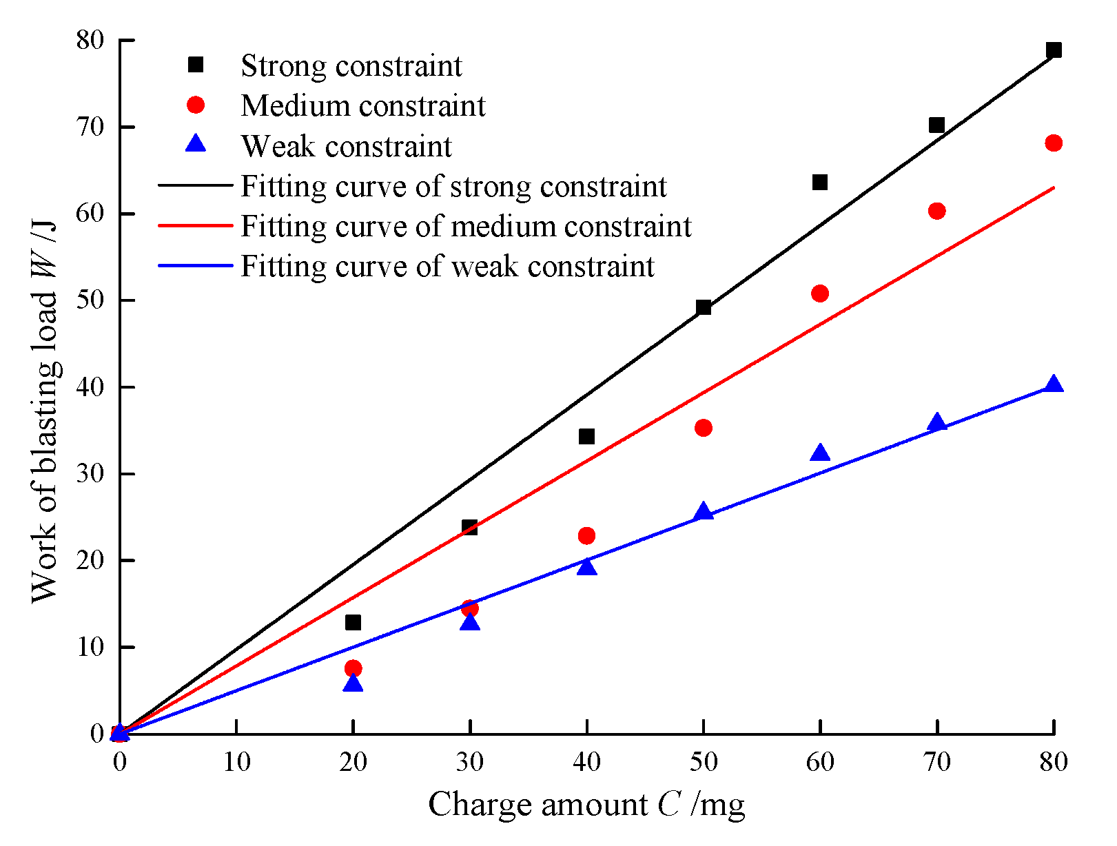
Furthermore, according to the data in Table 1, the relationship and the corresponding fitting curves between the charge amount C and the work of blasting load W were obtained and are shown in Figure 7. It can be seen from the fitting curve that W and C satisfy a linear relationship. The fitting relationship under the strong constraint condition is W = 0.98C, the fitting relationship under the medium constraint condition is W = 0.79C, and the fitting relationship under the weak constraint condition is W = 0.50C. The slope of the fitting curve indicates the work of blasting load of per unit mass explosive under the current constraint condition, which can be called the unit mass work of the explosive Wu. Thus, the Wu under the strong, medium, and weak constraint conditions is 0.98 J/mg, 0.78 J/mg, and 0.50 J/mg, respectively, and these works are all contributed by the blasting gas. It can be seen that with the weakening of the constraint condition, the Wu is gradually reduced. It should be noted that an approximate calculation method was adopted for the work of blasting load, ignoring the change of the gravitational potential energy of the water column and the work of frictional resistance between the water column and the wall of the water injection hole during the jet process. Therefore, the actual unit mass work of the explosive should be greater than the above calculated value.
A large number of underwater explosion experiments that study the energy distribution characteristics of blasting stress wave and blasting gas explosions indicate that the total energy E0 of the blasting stress wave and blasting gas generated by per unit mass explosive is approximately equal to the explosive heat Qv. The explosive heat Qv of Pb(N3)2 is 1.524 J/mg, as obtained by the calorimetry test. Therefore, it can be considered that the total energy of the blasting stress wave and blasting gas generated per unit mass explosive of Pb(N3)2 is E0Qv = 1.524 J/mg.
According to the above experimental analysis results, the ratio of Wu and E0 is called the utilization efficiency of the total energy ηt. The ηt under the strong, medium, and weak constraint conditions was respectively obtained as 64%, 51%, and 33%. As the constraint condition was weakened, the ηt also gradually reduced. Under the strong constraint condition, the blocking material is basically non-destructive and does not flush out of the borehole, and it can be considered that the blasting gas energy is completely converted into the work for the jetted water column. The water jet is caused by the action of the blasting gas, and the blasting energy is mainly composed of the blasting gas energy and the blasting stress wave energy. Based on this, the blasting gas generated by the explosion of Pb(N3)2 accounted for 64% of the E0, and the blasting stress wave energy accounted for 36% of the E0. This indicates that the blasting energy is mainly contained in the blasting gas, which is basically consistent with the conclusions of previous research [17]. Furthermore, the utilization efficiencies of the blasting gas energy ηg under the conditions of strong, medium, and weak constraint were 100%, 80%, and 52%, respectively.

4. Conclusions

Rock blasting fracture is the result of the combined action of the blasting stress wave and the blasting gas. The action effect of the blasting stress wave and blasting gas is an important part of the basic theory of rock blasting. In this paper, the designed experimental test specimen was used to shield the interference of the blasting stress wave from the experimental results, and the energy distribution characteristics of the blasting gas during the blasting process were studied.
Under the strong constraint condition, the blasting gas energy was basically converted into the kinetic energy of the jetted water column. The calculation and analysis of the experimental results show that the blasting gas energy of Pb(N3)2 and the blasting stress wave energy of Pb(N3)2 accounted for about 64% and 36% of the total energy, respectively. In addition, the utilization efficiencies of the total blasting energy under the strong, medium, and weak constraint conditions were 64%, 51%, and 33%, respectively, and the utilization efficiencies of the blasting gas energy were 100%, 80%, and 52%, respectively. It can be seen that as the constraint condition was weakened, the utilization efficiency of the total blasting energy and the utilization efficiency of the blasting gas energy were both reduced. Therefore, the blocking constraint effect of borehole is crucial for the efficient use of blasting energy in rock blasting engineering.
It is worth noting that the conclusions of this paper are mainly based on the blasting experiment with a small quantity of charge, and there is still a certain gap with actual engineering applications. In addition, limited to experimental conditions, this paper only used Pb(N3)2 as an explosive to carry out experimental research, and approximate treatment was used in the calculation of the blasting energy of the explosive. Therefore, the universality of the relevant conclusions is still worthy of further study. However, this work provides a new idea for studying the energy distribution characteristics of rock blasting, and reveals the effect of the borehole blocking condition on the utilization of blasting energy to some extent.

Author Contributions

All authors provided technical input; C.D. and R.Y. drafted the paper; C.C., Z.L. and C.Z. helped to perform the experiment; all authors reviewed the paper; R.Y. finalized the paper. All authors have read and agreed to the published version of the manuscript.

Funding

This research was supported by the National Natural Science Foundation of China (51934001, 51664007) and the National Key Research and Development Program of China (2016YFC0600903).

Conflicts of Interest

The authors declare no conflict of interest.

References

  1. Yang, R.; Ding, C.; Yang, L.; Lei, Z.; Zhang, Z.; Wang, Y. Visualizing the blast-induced stress wave and blasting gas action effects using digital image correlation. Int. J. Rock Mech. Min. Sci. 2018, 112, 47–54. [Google Scholar] [CrossRef]
  2. Li, M.; Zhu, Z.M.; Liu, R.F.; Liu, B.; Zhou, L.; Dong, Y.Q. Study of the effect of empty holes on propagating cracks under blasting loads. Int. J. Rock Mech. Min. Sci. 2018, 103, 186–194. [Google Scholar] [CrossRef]
  3. Silva, J.D.; Amaya, J.G.; Basso, F. Development of a predictive model of fragmentation using drilling and blasting data in open pit mining. J. S. Afr. Inst. Min. Metall. 2017, 117, 1089–1094. [Google Scholar] [CrossRef] [Green Version]
  4. Zhang, Z. Kinetic energy and its applications in mining engineering. Int. J. Min. Sci. Technol. 2017, 27, 237–244. [Google Scholar] [CrossRef]
  5. Persson, P.; Lundborg, N.; Johansson, C. The basic mechanisms in rock blasting. In Proceedings of the International Society of Rock Mechanics Proceedings, Lisbon, Portugal, 22 September 1970. [Google Scholar]
  6. Cho, S.H.; Kaneko, K. Influence of the applied pressure waveform on the dynamic fracture processes in rock. Int. J. Rock Mech. Min. Sci. 2004, 41, 771–784. [Google Scholar] [CrossRef]
  7. Aliabadian, Z.; Sharafisafa, M.; Mortazavi, A.; Maarefvand, P. Wave and fracture propagation in continuum and faulted rock masses: Distinct element modeling. Arab. J. Geosci. 2014, 7, 5021–5035. [Google Scholar] [CrossRef]
  8. Wang, J.; Cheng, Y. Simulating test on the working process of explosion gases. Blasting 1998, 2, 5–9. (In Chinese) [Google Scholar]
  9. Banadaki, M.M.D.; Mohanty, B. Numerical simulation of stress wave induced fractures in rock. Int. J. Impact Eng. 2012, 40, 16–25. [Google Scholar] [CrossRef]
  10. Yang, R.; Ding, C.; Wang, Y.; Chen, C. Action effect study on medium under loading of explosion stress wave and explosion gas. Chin. J. Rock Mech. Eng. 2016, 35, 3501–3506. (In Chinese) [Google Scholar]
  11. Cho, S.H.; Kaneko, K. Rock fragmentation control in blasting. Mater. Trans. 2004, 45, 1722–1730. [Google Scholar] [CrossRef] [Green Version]
  12. Kutter, H.K.; Fairhurst, C. On the fracture process in blasting. Int. J. Rock Mech. Min. Sci. 1971, 8, 181–202. [Google Scholar] [CrossRef]
  13. Yang, X.; Wang, M. Mechanism of rock crack growth under detonation gas loading. Explos. Shock Waves 2001, 21, 111–116. (In Chinese) [Google Scholar]
  14. Trivino, L.F.; Mohanty, B. Assessment of crack initiation and propagation in rock from explosion-induced stress waves and gas expansion by cross-hole seismometry and FEM-DEM method. Int. J. Rock Mech. Min. Sci. 2015, 77, 287–299. [Google Scholar] [CrossRef]
  15. Mchugh, S. Crack extension caused by internal gas pressure compared with extension caused by tensile stress. Int. J. Fract. 1983, 21, 163–176. [Google Scholar] [CrossRef]
  16. Brinkmann, J.R. An experimental study of the effects of shock and gas penetration in blasting. In Proceedings of the Third International Symposium on Rock Fragmentation by Blasting—Fragblast 3, Brisbane, Australia, 15 January 1990. [Google Scholar]
  17. Yan, S. Measurement of the explosion energy of the centralized charge and the linear charge underwater. Explos. Mater. 2003, 32, 23–27. (In Chinese) [Google Scholar]
Figure 1. The experimental setup of the water jet test.
Energies 13 05340 g001
Figure 2. Diagram of the test specimen structure of the three experimental groups.
Energies 13 05340 g002
Figure 3. Diagram of the water column, charge condition, and borehole constraint.
Energies 13 05340 g003
Figure 4. Diagram of the test specimen structure of the verification experiment.
Energies 13 05340 g004
Figure 5. Photos of the water jet under blasting load (weak constraint, C = 20 mg).
Energies 13 05340 g005
Figure 6. The relationship and the corresponding fitting curves between C and vmax.
Energies 13 05340 g006
Figure 7. The relationship and the corresponding fitting curves between C and W.
Energies 13 05340 g007
Table 1. The maximum jet velocity vmax and the work of blasting load W under different constraint conditions.
Charge Amount C/mg020304050607080
Strong constraintvmax/(m·s−1)0257350420503572601637
W/J012.8423.8134.2949.1863.6070.2278.88
Medium constraintvmax/(m·s−1)0197273343426511557592
W/J07.5414.4922.8735.2850.7660.3168.13
Weak constraintvmax/(m·s−1)0171255313362407429454
W/J05.6612.6719.0425.4932.2235.8040.16
Publisher’s Note: MDPI stays neutral with regard to jurisdictional claims in published maps and institutional affiliations.