Article

Development of HVRT and LVRT Control Strategy for PMSG-Based Wind Turbine Generators †

1
School of Electrical Engineering and Telecommunications, University of New South Wales, Sydney 2052, Australia
2
State Key Laboratory of Power System, Department of Electrical Engineering, Tsinghua University, Beijing 100084, China
*
Author to whom correspondence should be addressed.
This Paper Is an Extended Version of “Coordinated HVRT and LVRT Control Scheme for PMSG-Based Wind Farm” Published in the Proceedings of the 29th Australasian Universities Power Engineering Conference, Fiji, 26–29 November 2019.
Energies 2020, 13(20), 5442; https://doi.org/10.3390/en13205442
Submission received: 20 September 2020 / Revised: 12 October 2020 / Accepted: 14 October 2020 / Published: 19 October 2020
(This article belongs to the Special Issue IOT in Energy System Sustainability)

Abstract

:
Various challenges are acknowledged in practical cases with high wind power penetration. Fault ride-through (FRT) capability has become the most dominant grid integration requirements for the wind energy conversion system worldwide. The high voltage ride-through (HVRT) and low voltage ride-through (LVRT) performance play a vital role in the grid-friendly integration into the system. In this paper, a coordinated HVRT and LVRT control strategy is proposed to enhance the FRT capability of the permanent magnet synchronous generator (PMSG)-based wind turbine generators (WTG). A dual-mode chopper protection is developed to avoid DC-link overvoltage, and a deadband protection is proposed to prevent oscillations under edge voltage conditions. The proposed strategy can ride through different levels of voltage sags or swells and provide auxiliary dynamic reactive power support simultaneously. The performance of the proposed control scheme is validated through various comparison case tests in PSCAD/EMTDC.

1. Introduction

The renewable energy has been widely acknowledged as an essential solution to climate change and the energy crisis. With the significant development of energy conversion technologies, much attention has been attached to the clean energy generation [1]. In 2019, there were 34 large-scale renewable energy projects completed, increasing Australia’s large-scale renewable power generation by 2.2 GW. Among the renewables, the installed wind energy capacity in 2019 was 837 MW, and wind energy has overtaken hydro as Australia’s leading renewable energy source, which accounts for more than 35% of the total clean energy generation [2]. The significantly increasing installed capacity of wind power has brought lots of advantages and disadvantages. On 28 September 2016, a catastrophic blackout incident hit South Australia across the state, which is the first known blackout event in a power system with high renewable energy penetration [3,4]. It was later concluded that wind farms were to blame for the catastrophic blackout incident, and the cascading trip of wind farms triggered by extreme weather events was one of the primary causes of the incident [5]. After the blackout event, different versions of National Electricity Rules (NER) were revised by the Australian power system operator to address the grid-friendly integration of the renewables. Specifically, the grid integration requirements for clean energy sources have become stricter and stricter. Apart from Australia, different system operators all over the world have published various strict grid integration requirements for renewable energy, especially targeting at fault ride-through (FRT) capabilities.
The current challenge of high voltage ride-through (HVRT) and low voltage ride-through (LVRT) capabilities lies in the inherent intermittency and uncertainty of wind power integration. In the current wind energy technology, there are two mainstream variable speed wind turbine generators (WTG) [6]. The doubly fed induction generator (DFIG) is also called the type 3 WTG, and the permanent magnet synchronous generator (PMSG) is also known as the type 4 WTG [7]. The PMSG usually uses a full-scale converter with no existence of a gearbox, while the DFIG commonly adopts a partial-scale converter and requires a gearbox. The back-to-back converter in PMSG results in superior control performance, as well as high cost. To meet the exhaustive grid integration requirements, different control schemes have been proposed for different WTGs. A complex LVRT control scheme for DFIG was presented in [8]. In the control scheme, different parameters of the controller could adaptively adjust according to various fault situations, and an enhanced rotor-side converter (RSC) reactive power management was also presented. Another comprehensive LVRT control strategy was proposed for DFIG-based WTGs in [9], which combined crowbar and adaptive series resistance to enhance the LVRT capability. However, in this method, the dynamic reactive power support was not considered. In [10], a comprehensive LVRT control strategy was proposed with additional battery storage devices for DFIG-based WTGs, which achieved dynamic reactive current injection and smooth grid fault recovery with inevitable high costs. In [11], a proportional-resonant (PR) regulator-based control strategy for DFIG-based WTGs was designed according to the Spanish grid codes. In this method, the grid-side converter (GSC) is utilized to provide reactive power support and mitigate oscillations under unbalanced grid fault situations.
With respect to PSMG-based WTGs, a two-stage control strategy was proposed to enhance the FRT capability under different grid faults, which combined DC-link voltage control bandwidth tuning and active damping control to reduce the shaft stress [12]. Another LVRT control method for PMSG-based WTGs was proposed in [13], which utilized the feedback linearization. The capacitor voltage is controlled by the machine-side converter (MSC) rather than the GSC. Unlike [12,13], which aim to achieve smooth fault-ride through based on the WTG itself, the external equipment like a static synchronous compensator (STATCOM) is utilized to provide auxiliary reactive power support to enhance the FRT capability in [14]. Apart from those strategies, a coordinated instantaneous active power control method was proposed in [15], which combines the machine-side and grid-side active power. A sliding mode control-based control scheme for PMSG-based WTG was also presented in [16], providing auxiliary reactive power support and maintaining the energy balance. On the other hand, HVRT is a comparatively emerging topic, which has not yet been extensively researched. In [17], an HVRT control method for the PMSG was proposed based on the closed-loop modulation voltage control, but the grid voltage swell considered in the research was relatively small. Another HVRT approach for the DFIG was proposed in [18], which adopts a virtual impedance control method to enhance the HVRT performance.
To meet the increasingly stringent grid integration requirements, this paper aims to develop a coordinated control scheme for PMSG-based WTG to improve the HVRT and LVRT performance. The main contributions are summed up in three aspects: (1) Different grid integration requirements of leading wind power countries are detailed introduced and compared; (2) based on the dual-mode chopper circuit and auxiliary reactive power support, a coordinated FRT control strategy is proposed to enhance the performance during the different level of grid fault; (3) various comparison tests are carried out to verify the improvement of the FRT capability.
The reminder of this paper is structured as follows. In Section 2, grid codes of selected countries are detailed, presented and compared. Section 3 denotes the modeling of WTG and conventional vector control methods. In Section 4, based on the analysis of transient behaviors during grid faults conditions, a comprehensive control strategy combining dual chopper protection and auxiliary reactive power support is presented. Various comparison tests are conducted in Section 5 to validate the effectiveness of the proposed approach, and the final section draws the conclusion.

2. Grid Codes in Different Nations

The development of wind power generation in different countries varies from each other. To make the most of the wind energy, the developed wind energy countries have introduced a series of grid codes to meet their grid integration requirements. Among the issues wind power generation are facing, FRT capability is a major one. According to the utility grid codes, wind power plants (WPP) should have enough HVRT and LVRT capabilities. An example of typical HVRT and LVRT requirements is shown in Figure 1, which indicates that the WTG should remain interconnected if the grid voltage is within the twilled blue area. If the grid voltage is outside that area, the WTG will be authorized to trip with no punishment. It is widely adopted that the WTG should operate for a long time if the terminal voltage falls between 0.9 pu and 1.1 pu, while it only needs to be connected for a short period in other voltage conditions.
The mainstream grid codes for FRT from different nations are listed and compared in Table 1 [19,20,21,22,23,24,25]. It is shown that, for LVRT, zero voltage ride-through (ZVRT) is also essential in most of the grid codes. On the other hand, for HVRT, it is required that the WTG should stay interconnected when the grid voltage is within [1.10, 1.30] pu by most of the grid codes. Under different undervoltage and overvoltage conditions, WTGs are required to stay connected from milliseconds to seconds.

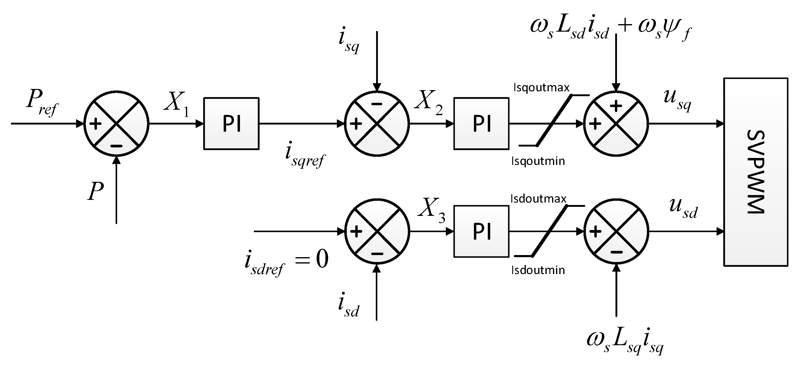
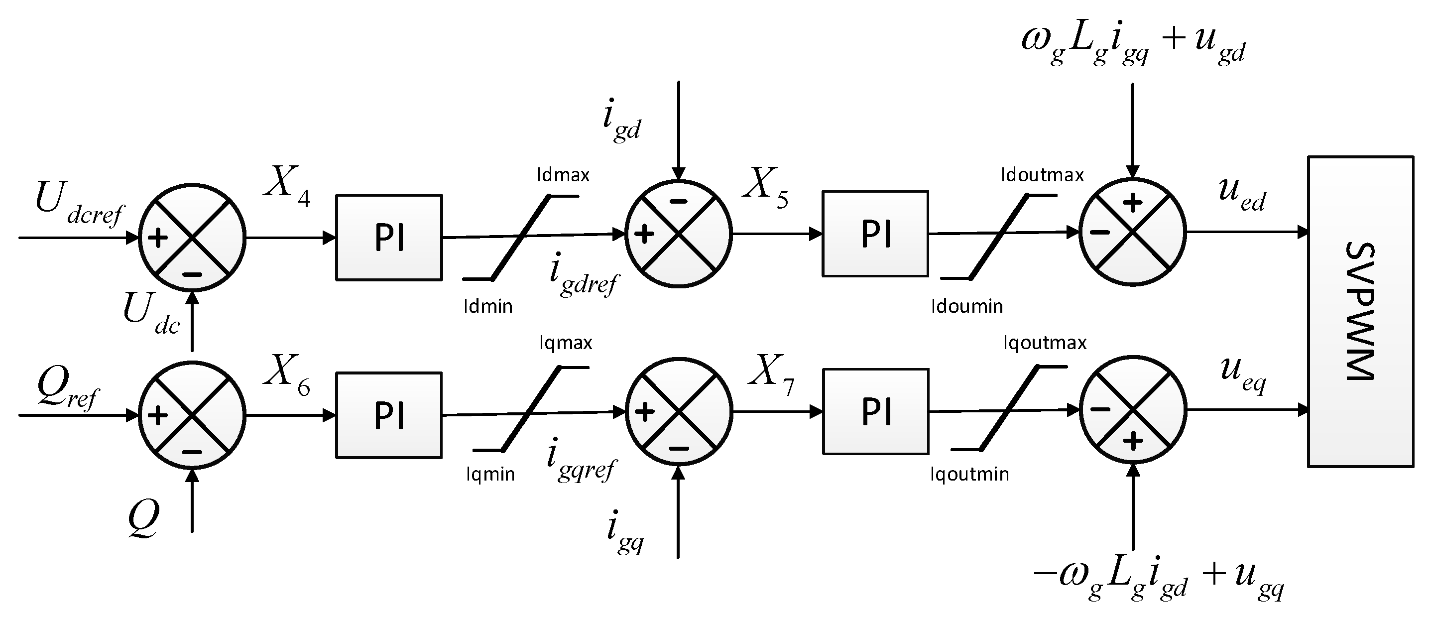
3. WTG Modeling and Control Strategy

As mentioned previously, among the two mainstream WTG, the direct-driven PMSG (DD-PMSG) has benefits such as better reliability and higher power generation efficiency than the DFIG. The main objective of the paper is to improve the FRT capability for the PSMG-based WTG. Attributed to its full-scale converter, PMSG-based WTG is capable of providing auxiliary reactive power support during various grid faults. The configuration of the WTG system is denoted in Figure 2, which consists of a wind turbine (WT), a DD-PMSG, an MSC, a DC-link capacitor, a GSC and a transformer. Table 2 lists the parameters of the test system.
The performance of the MSC and GSC has a great influence on the safe and stable operation of the WTG. The modeling and the conventional vector control method are presented as follows. As for the MSC, the stator dynamic equations in the rotor reference frame are described as (1)
{ u s d = R s i s d + L s d d i s d d t ω s L s q i s q u s q = R s i s q + L s q d i s q d t + ω s L s d i s d + ω s ψ f
where u s d and u s q are the stator d-axis and q-axis voltages, respectively; i s d and i s q are the stator d-axis and q-axis current, respectively; L s d and L s q are the stator d-axis and q-axis inductances, respectively; R s is the stator windings resistance; ψ f is the magnetic flux; ω s is the angular frequency of the stator voltage.
As for GSC, the dynamic equations in the grid voltage oriented synchronous reference-frame are described as (2)
{ u e d = ( R i g d + L d i g d d t ) + u g d + ω L i g q u e q = ( R i g q + L d i g q d t ) + u g q ω L i g d
where u g d and u g q are the d-axis and q-axis components of the terminal voltage, respectively; u e d and u e q are the d-axis and q-axis components of the grid voltage, respectively; i g d and i g q are the d-axis and q-axis components of the terminal current, respectively; L and R are the lumped inductance and resistance of the transformer and the filter, respectively; ω is the angular frequency of the grid voltage.
Figure 3 and Figure 4 show the conventional vector control method for the MSC and the GSC, respectively. The MSC targets at the wind power managements, whereas the GSC aims to maintain the capacitor voltage stable and regulate the decoupled output power.

4. Coordinated HVRT and LVRT Control Strategy

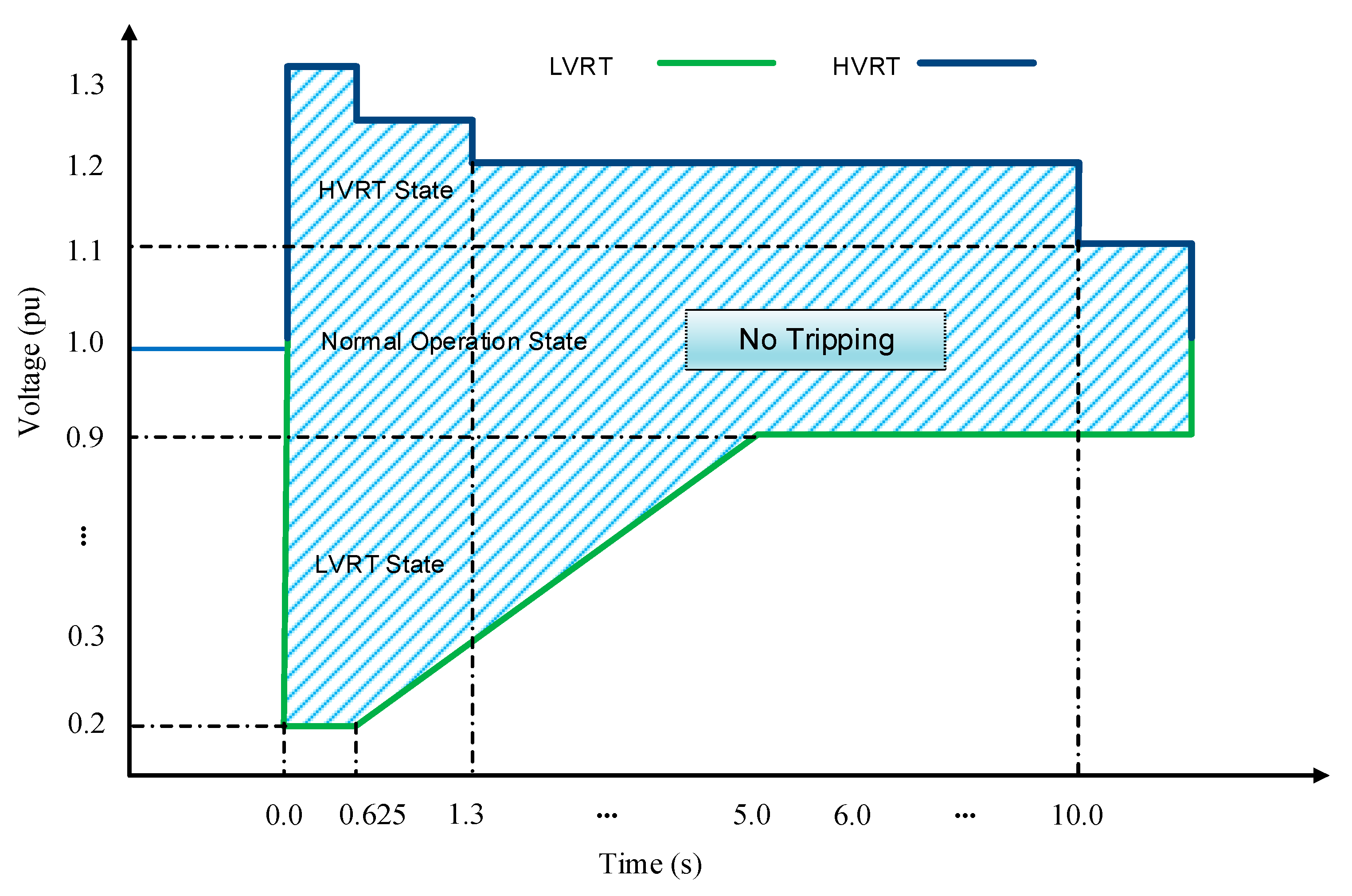
4.1. Transient Behaviors during HVRT and LVRT

In Figure 2, given that the losses between the PMSG and the converters are ignored and the system is in steady-state, the DC-link voltage will remain unchanged. In that case, Equation (3) is workable, which means that the PMSG generates electrical power from the wind, and then that electrical power is transmitted to the grid through the MSC and GSC.
P m = P e = P g
where P g is the active power transmitted to the utility grid; P e is the electrical power generated from the generator; and P m is the mechanical power harvested from the WT.
As for LVRT, the power balance between the P e and P g will not be workable if there is a grid voltage dip. The output current of the GSC cannot change immediately, which indicates that P g will decrease instantly because of the low voltage condition. Meanwhile, due to independence between MSC and GSC, the output of the MSC, P e , will not change immediately, causing the excess energy accumulated in the capacitor as expressed in (4).
Δ P = U d c I d c = 1 2 C d U d c 2 d t = P s P g
where Δ P is the excess energy accumulated in the capacitor; U d c and I d c are the voltage and current in the capacitor, respectively. Then, the GSC begins to inject more active current to dissipate the unbalanced energy in the DC-link capacitor. However, the fault is not yet cleared, and the grid voltage is still low, which means that the GSC cannot transmit enough power to the grid. Finally, the unbalanced energy continues to accumulate in the capacitor, leading to the overvoltage of the capacitor and, even worse, the trip of the whole system.
As for HVRT, the output of the MSC, P s , will remain unchanged if there is a grid voltage swell. In the meantime, the overvoltage situation could lead to the reverse energy flows back to the WTG. Hence, the unchanged output of the MSC and the reverse energy together result in the surge of the capacitor voltage, endangering the normal operation of the WTG [26].

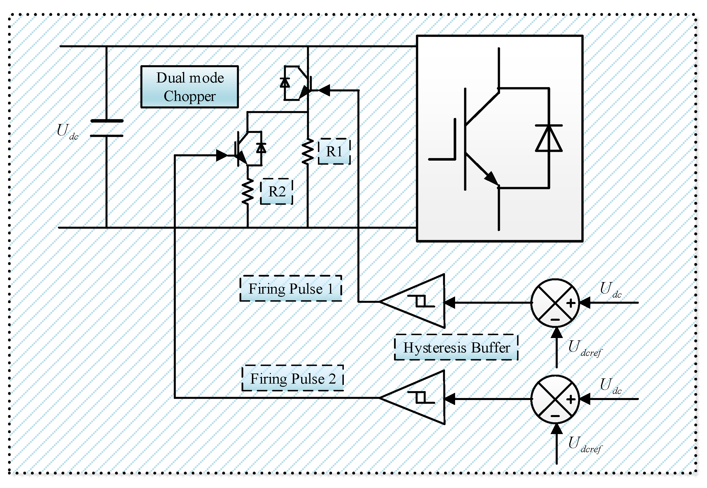
4.2. DC-Link Protection

As mentioned previously, both HVRT and LVRT will result in the unbalanced energy accumulating in the capacitor. The essence of improving FRT capability is to maintain the balance of the excess energy in the capacitor during faults. Generally, there are three main solutions, namely, (1) decreasing the electrical power generated from the generator, P e , (2) increasing the output power to the grid, P g , and (3) dissipating the unbalanced power in the DC-link, Δ P .
As for the first option, decreasing the electrical power generated from the PMSG is not a practical solution. One reason for that is the control of the pitch angle system for the wind turbine is a relatively slow dynamic process and cannot be immediately changed. Another reason is that the structure of the full-rated converter is able to achieve a few electromechanical interactions between the PMSG and the grid. Thus, the first option is not suggested. As for the second option, the GSC is able to inject maximum active current within the limitation of insulated gate bipolar transistor (IGBT) during faults, but little energy can be transmitted to the grid due to the low voltage conditions. In HVRT situations, it is also difficult to increase P g because of the inevitable reverse power flow. Thus, the idea of increasing output power during faults is not practical. As for the third option, additional devices may be needed to balance the excess energy such as a chopper protection circuit. The conventional chopper protection circuit is made up of an IGBT in series with a resistor, which is widely adopted for its low cost and easy implementation. However, the single resistor needs to work uninterruptedly under various faults conditions, which frequently results in overheating problems. For that reason, a dual-mode chopper circuit is proposed, and the configuration and control strategy are shown in Figure 5.
To mitigate the DC-link voltage surge caused by the unbalanced energy, the mechanism of the dual-mode chopper is depicted as follows: R1 is in series with the IGBT1, and R2 and IGBT2 is in parallel with R1. The resistance of R1 is slightly larger than R2. The difference between the instantaneous capacitor voltage and the reference capacitor voltage is dispatched to a hysteresis buffer 1, where the firing pulse 1 is generated and dispatched to the IGBT1 to dispel the unbalanced energy via R1. In the meantime, the voltage difference is also sent to another hysteresis buffer 2 to generate the firing pulse 2 for the R2.
The resistance of R1 and R2 plays a significant role in the effectiveness of the dual-mode chopper circuit. The influence is denoted as follows: If the equivalent resistance of R1 and R2 is too large, the unbalanced energy cannot be dissipated immediately. On the other hand, if the equivalent resistance is not large enough, the maximum heat tolerance of the dual-mode chopper will become extremely high, which will inevitably raise the cost. To select an appropriate equivalent resistance, the upper and lower limits can be expressed as:
U d c m i n I d c m a x R U d c m a x I d c m a x
where I d c m a x is the maximum allowed current in the capacitor; U d c m a x and U d c m i n are the upper and lower thresholds of the capacitor voltage, respectively. Selecting U d c m i n = 1150 V, U d c m a x = 1300 V and I d c m a x = 1350 A, then the equivalent resistance is within [0.852, 0.963] ohm. Moreover, the difference between R1 and R2 will also affect performance. When the voltage drop is not large, the unbalanced energy is dissipated by R1, keeping the capacitor voltage stable. When the grid voltage drop is relatively large, R1 is additionally put into service to dissipate the excess energy. After tuning by simulations, R1 is set as 2.0 ohms, and R2 is set as 1.8 ohms.

4.3. Dynamic Reactive Current Injection

It has been widely acknowledged that the PMSG-based WTG is capable of injecting reactive current during faults, which is also demanded by most of the grid codes nowadays. To make the most of the auxiliary support from the full-scale converter, the following control methods are proposed. In this control strategy, the reactive current reference depends on the operation mode of the WTG. If the WTG is in normal operation, the reactive current reference is generated by the reactive power reference from the power plant controller. If the WTG is in FRT mode, then the dynamic reactive current reference is calculated by the depth of the voltage sags, which is expressed as follows:
i g q r e f = K I N ( U N U )
where K is the coefficient; i g q r e f is the reactive current reference; U is the instantaneous terminal voltage; U N and I N are the nominal voltage and current of the WTG. If the terminal voltage is below the nominal voltage, there will be a capacitive current reference sent to the converter. If the terminal voltage is above the nominal voltage, there will be an inductive current reference. Since the total current of the GSC is limited by the current threshold of the IGBT, the active current reference then should be limited by the following equation during FRT mode:
i g d r e f I m a x 2 i g q r e f 2
where I m a x is the maximum allowed current of the IGBT, and i g d r e f is the active current reference. The maximum allowed current is set to be 1.8 pu in this work.
In Figure 6, it is observed that in the normal operation mode, the active and reactive reference are the same as the conventional vector control. In FRT mode, the i g q r e f switches to (6) to provide auxiliary capacitive or inductive reactive power support, whereas the limit of the i g d r e f is within the range of the maximum allowed current of the IGBT. In this way, the GSC is set to be the Q-priority mode, which means the converter focuses more on the reactive current contribution rather than active current during HVRT and LVRT events.
The injected amount and timing of reactive current play an important role in the transient performance during faults. Theoretically, the more the injected reactive current is, the better improvement of the terminal voltage profile will be. However, the total amount of output current is limited by the IGBT hardware. As shown in (7), the injected amount of active current is limited by the injected amount of the reactive current. On the other hand, the amount of the active current is essential to the energy transfer from DC-link to the grid. If the active current is too small, there will be a huge amount of unbalanced energy built up in the capacitor, which could lead to the overheating of the chopper circuit and cause protection trips. Moreover, the timing of the reactive current injection is also critical to transient behaviors. Most of the grid codes require a fast, reactive current response. For example, in Australia, the rise time of the reactive current injection should be smaller than 40 ms and the settling time also should be smaller than 70 ms [23]. An instant reactive current injection will achieve great transient performances during faults, but it may also lead to maloperations and overuse of the switches. Hence, the injected timing should be small enough to ensure fast grid voltage support, yet not too small to avoid maloperation and overuse of the switches. The injection time delay is set as 10 ms in this test.

4.3.1. Maximum Iq Injection under Deep Voltage Dip

As mentioned before, most grid codes around the world include ZVRT requirement. To further enhance the performance under deep voltage dip, a maximum Iq injection strategy under server voltage dip is proposed, which means the WTG will inject maximum reactive current once the voltage is below the threshold. In this paper, the threshold is set to be 0.2 pu. Thus, the overall reactive current reference under various voltage conditions are described as in (8). When the WTG terminal voltage falls within 0.9 pu and 1.1 pu, the WTG operates normally. When the voltage is above 1.1 pu or between 0.2 pu and 0.9pu, the WTG injects desired reactive current as in (6). When the voltage is below 0.2 pu, the WTG injects the maximum reactive current within its limit.
i g q r e f = { K H V R T ( U N U ) I N U > 1.1 p u i g q c m d 0.9 p u U 1.1 p u K L V R T ( U N U ) I N 0.2 p u U < 0.9 p u K max I N U < 0.2 p u
where U N and I N are the nominal voltage and current, respectively; K L V R T and K H V R T are coefficients of 1.5 and 2.0, respectively; K max is set to be 1.8.

4.3.2. Deadband Protection under Edge L/HVRT Conditions

The dynamic reactive current support does improve the voltage profile in L/HVRT events by providing more reactive power. However, it will also bring up some other issues under certain edge conditions. Consider the following scenario: When the voltage is just shy of 0.9 pu, the WTG detects an LVRT event and then injects a certain amount of reactive current. After that, the terminal voltage will ascend because of the increased capacitive reactive power at the WTG terminal and then exit the LVRT mode. Meanwhile, if the WTG exits LVRT mode and the fault is not yet cleared, the WTG will fall into LVRT mode again. The repetitive in and out LVRT mode under edge conditions could lead to oscillations, posing danger to the safe operation of the WTG. This type of oscillation could also happen under the edge HVRT conditions.
In order to overcome the oscillations under edge conditions, a deadband protection strategy is proposed and depicted in Figure 7.
As shown in Figure 7, set reset (SR) latches are adopted to generate the deadband. First, the filtered terminal voltage is compared with the upper and lower thresholds and then sent to S and R inputs, respectively. After that, the flag for the HVRT and LVRT is generated through a delay component. Considering the aforementioned scenario of edge voltage conditions, when the voltage is just below 0.9 pu, the WTG injects dynamic reactive current. The voltage rises a little bit but still is within the deadband. The WTG will not repeatedly enter and exit the LVRT mode. Thus, there will be no oscillations. To achieve the dead protection, for LVRT the detection in voltage should be smaller than the out voltage and vice versa for HVRT. In this paper, LVRT_in_Vol and LVRT_out_Vol are set to be 0.90 and 0.93, respectively. HVRT_in_Vol and HVRT_out_Vol are set to be 1.10 and 1.07, respectively.

4.4. Coordinated L/HVRT Control Scheme

In this section, the coordinated HVRT and LVRT control strategy is formulated by combining the dual-mode chopper protection and the dynamic reactive power support. The complete process is denoted in Figure 8. In normal conditions, the dual-mode chopper protection does not engage, and the WTG operates normally. When there is a sever voltage dip or swell, the WTG switches into FRT mode, and the dual-mode chopper protection will activate if the capacitor voltage is above the threshold. In FRT mode, if the voltage is below 0.2 pu, the WTG will immediately inject maximum reactive current. A deadband protection scheme is added to prevent oscillations under edge voltage conditions. The detailed validation simulations will be presented in the following section.

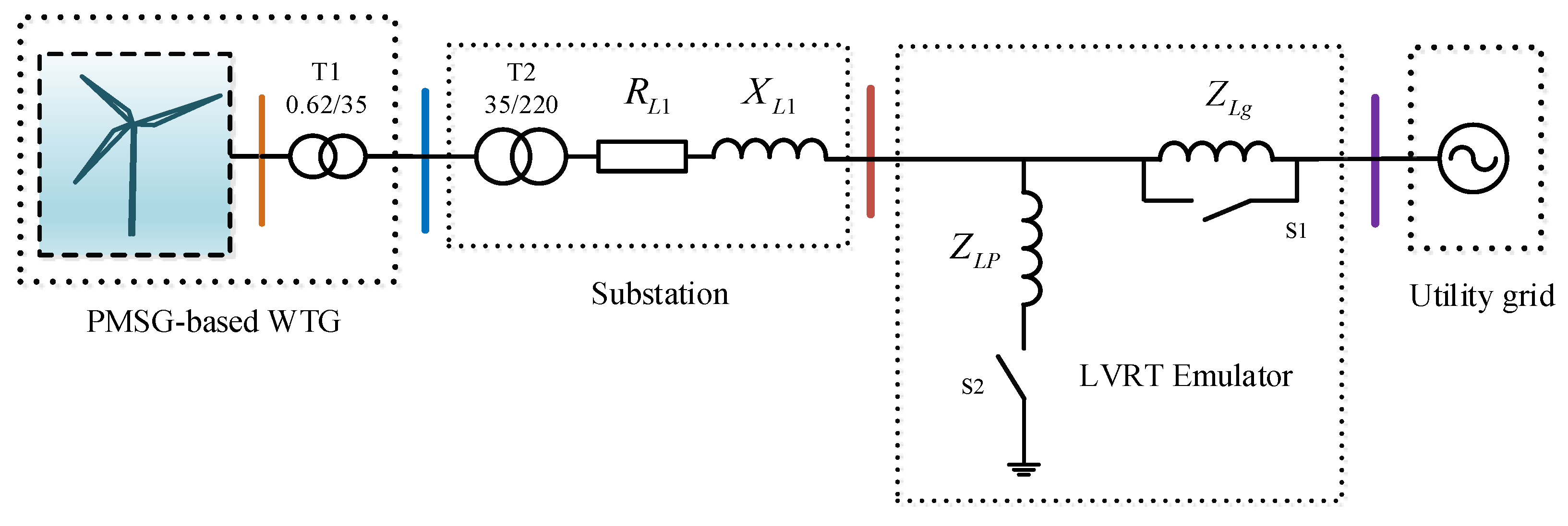
5. Simulation Validation

In the section, different comparison tests are conducted to verify the effectiveness of the coordinated control scheme in PSCAD. The brief layout of the WTG system and the grid fault emulator is depicted in Figure 9.
In Figure 9, the test system is made up of a PMSG-based WTG, transformers T1 and T2, an equivalent transmission line, a grid faults emulator, and an ideal grid. To acquire more practical results, a grid faults emulator based on the IEC 61400-21 is adopted rather than modifying the utility grid voltage in the software [27]. The grid impedance Z L g is utilized to reflect the influence of the short circuit ratio on the system strength. By definition, the short circuit ratio (SCR) at the point of interconnection (POI) is calculated as follows:
S C R P O I = S S C C S W P P
The short circuit capacity (SCC) at POI is calculated as in (10)
S S C C = V P O I 2 Z L g = V P O I 2 R L g 2 + X L g 2
Selecting the POI voltage and WTG nominal capacity as the base value, then the SCR can be derived as the inverse of the grid impedance Z L g as shown in (11).
S C R P O I = S S C C S W P P = V P O I   p u 2 Z L g   p u = 1 Z L g   p u
In the following comparison tests, the SCR at POI is set as 5 and the X/R ratio is set as 10. It should be pointed out that the system strength plays a significant role in the transient behaviors of the WTG. The impedance of Z L g should be selected so that the WTG can still operate normally with the voltage drop, and meanwhile, meaningful fault response of the WTG can still be acquired.
The mechanism of the grid fault emulator is denoted as follows. The change of SCR at the POI is created by the by-pass connection of Z L g prior and after the drop. As for the LVRT emulator, the Z L P . is made up of an inductor in series with a resistor. The operation of S2 is applied to connect the impedance Z L g and create the voltage drop. Various depths of voltage drop can be obtained by modifying the impedance of the Z L P . As for the HVRT emulator, the inductor in the Z L P is replaced by a capacitor. Various levels of grid voltage surge could be achieved by changing the impedance of the Z L P as well. It should be noted that the series resistor is applied to generate additional damping and avoid unnecessary oscillations.

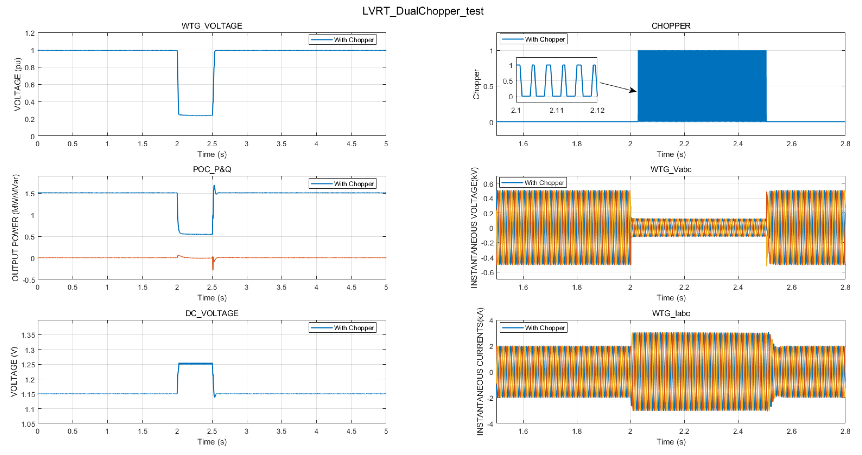
5.1. Dual-Mode Chopper Protection Test

In the test, a 0.22 pu grid fault was applied to validate the performance of the dual-mode chopper protection. In Figure 10, the voltage decreased to 0.22 pu at t = 2.0 s, and then the voltage recovered to 1.0 pu at t = 3.5 s. It is observed that the capacitor voltage increases immediately when the voltage drops. That is because there is unbalanced energy accumulated in the capacitor. After that, the dual-mode chopper circuit activates to dispel the unbalanced energy, and then the capacitor voltage is maintained around 1.25 kV. The comparison study with no chopper protection is not presented in Figure 10 because under such severe voltage drop conditions, the DC-link voltage will continue to rise and the unbalanced energy will eventually cause the overheat in the capacitor, resulting in the trip of the WTG. It should be pointed out that during LVRT, the active power output of the WTG drops a lot due to the low voltage situation, while the reactive power output remains almost stable because of the unchanged reactive current reference. The three-phase instantaneous current remains stable, and no obvious waveform distortion can be observed under this fault situation. The result indicates that the DC-link protection can effectively prevent the overvoltage of the capacitor. In HVRT events, the DC-link voltage also rises and then the chopper circuit engages to protect the DC-link. The simulation result is similar to the LVRT event and not repeatedly presented here.

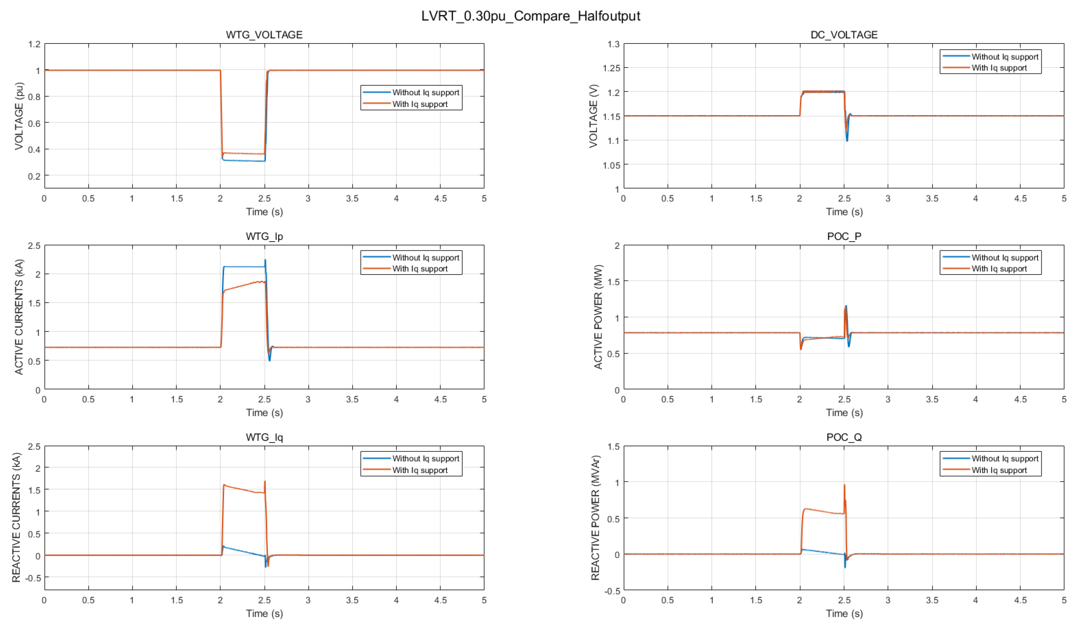
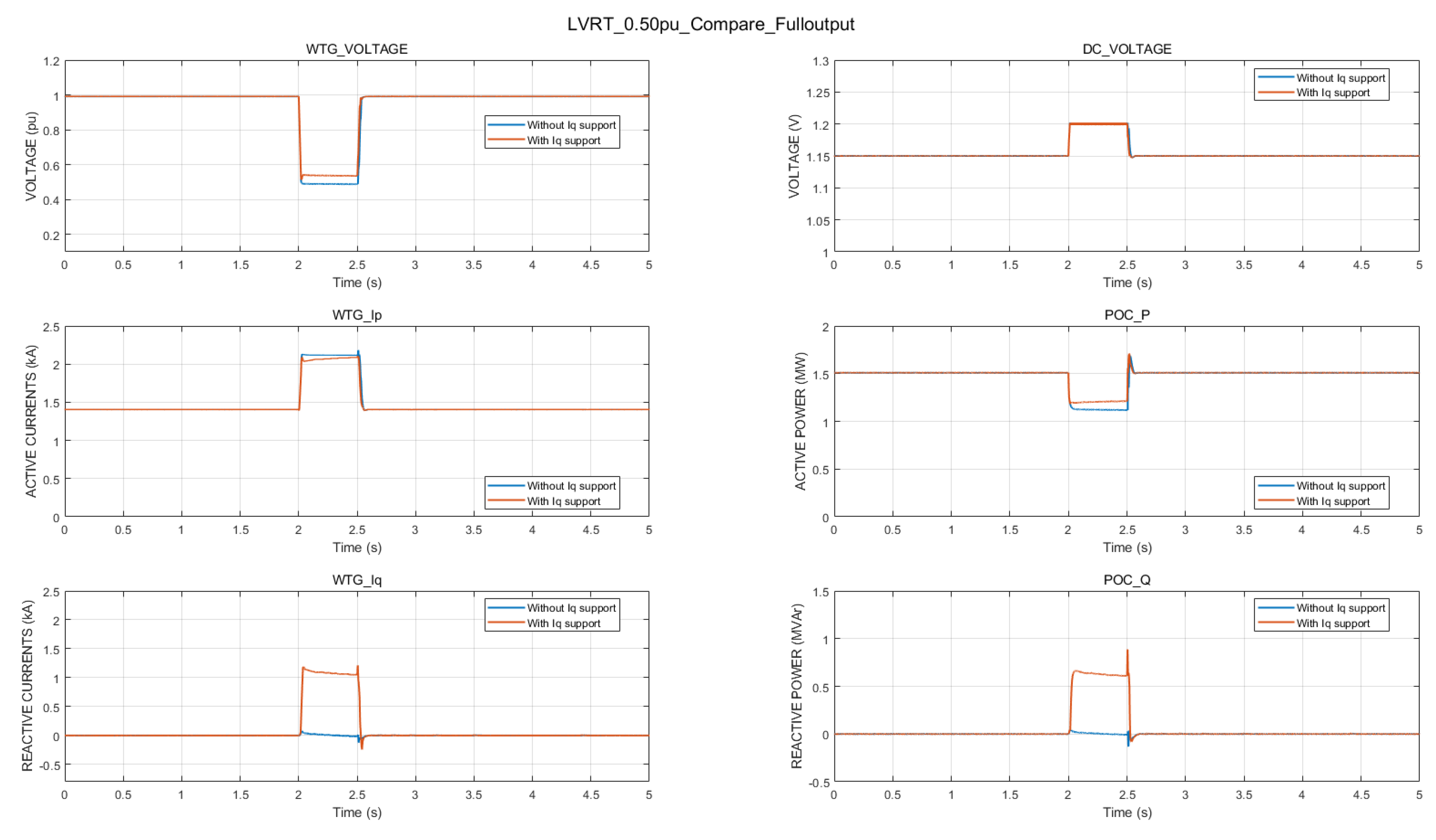
5.2. Comparison Tests under Different LVRT Conditions

In the comparison study, 0.30 pu and 0.50 LVRT events were carried out. Both of the faults were applied at t = 2.0 s, and the voltage recovered to 1.0 pu at t = 2.5 s. In Figure 11 and Figure 12, it is clear that both WTG survive the undervoltage conditions. The difference between the proposed method and the conventional method is that, under undervoltage situations, the WTG voltage with dynamic reactive current injection is obviously higher than the one with no reactive current injection, which means the dynamic reactive current contribution effectually provides auxiliary reactive power support and improves the terminal voltage profile under LVRT situations.

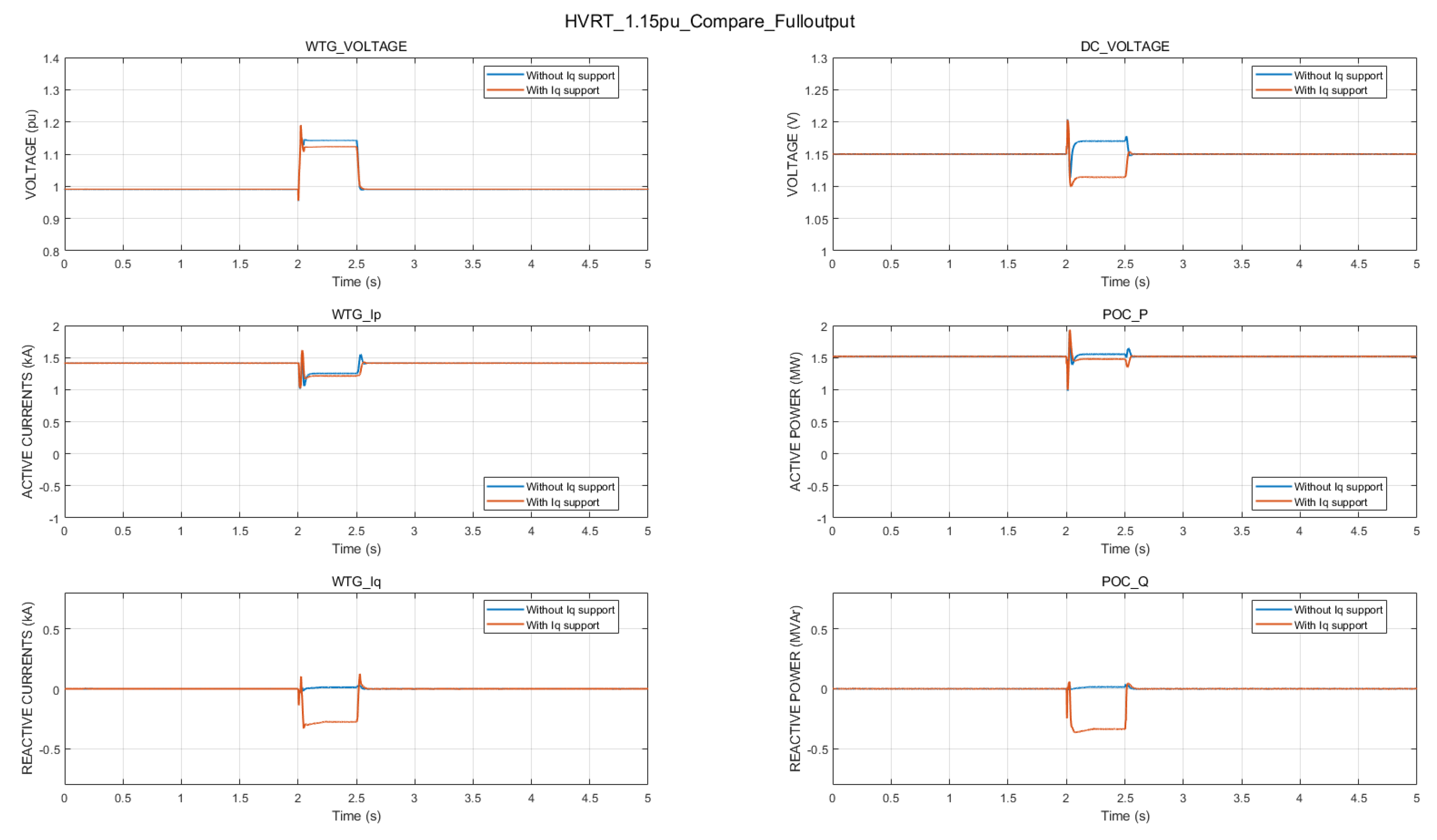
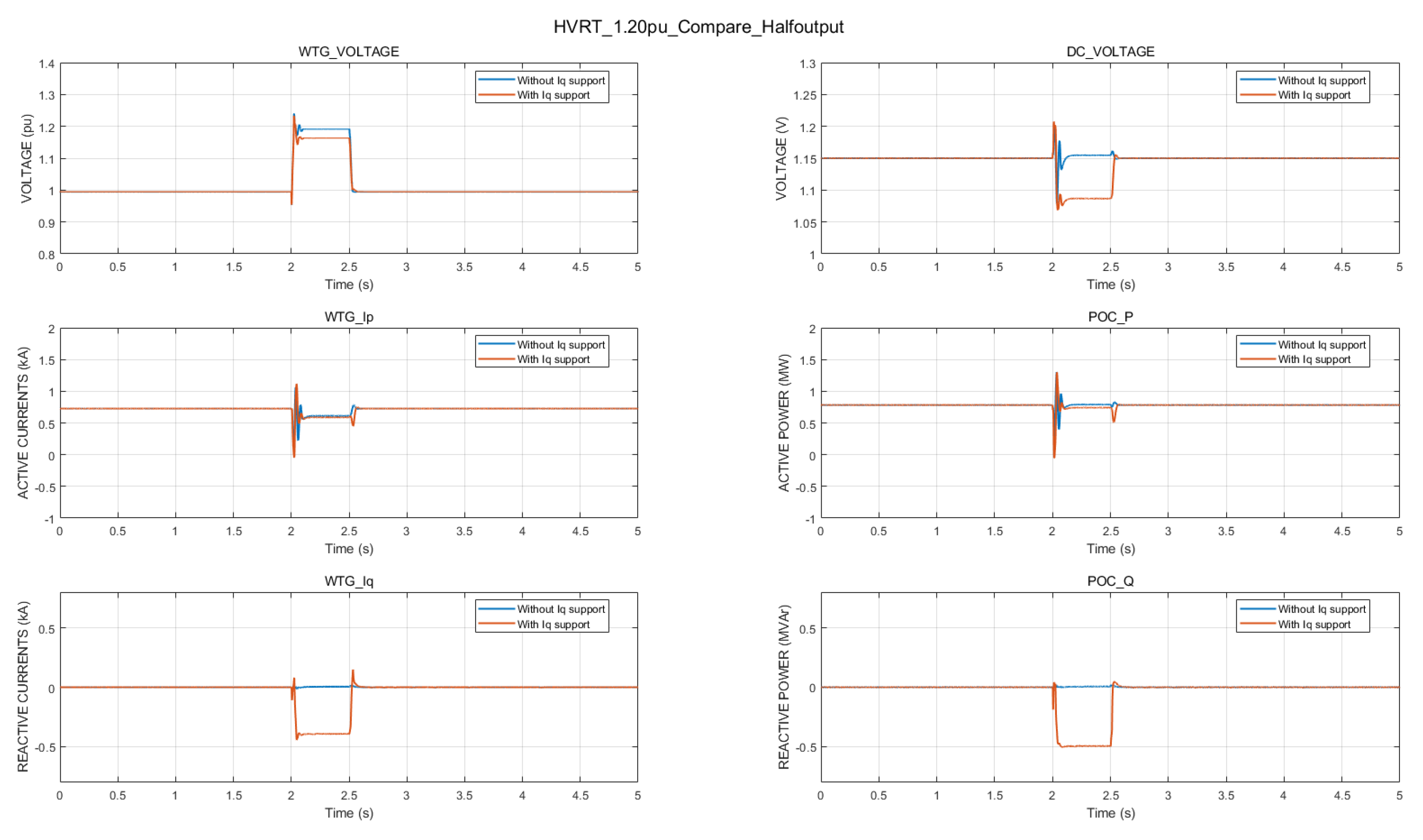
5.3. Comparison Tests under Different HVRT Conditions

In the comparison study, 1.15 pu and 1.20 pu HVRT events were carried out. Both of the faults were applied at t = 2.0 s, and the voltage recovered to 1.0 pu at t = 2.5 s. In Figure 13 and Figure 14, it is clear that both WTG survive the overvoltage conditions. The difference between the proposed method and the conventional method is that, under overvoltage situations, the WTG voltage with dynamic reactive current injection is obviously lower than the one with no reactive current injection, which means the dynamic reactive current contribution effectually provides auxiliary reactive power support and improves the voltage profile under HVRT situations.

5.4. Comparison Tests under Edge LVRT Conditions

In the comparison study, an edge 0.90 pu grid fault was applied at t = 2.0 s, and the voltage recovered to 1.0 pu at t = 2.5 s. In Figure 15, both simulation results show that the WTG survive the undervoltage condition. Compared with the one without deadband protection, the WTG terminal voltage with deadband protection is clearly more stable during an edge LVRT event. Obvious oscillations in terminal voltage and reactives can be observed during the fault. As shown in the Flag_FRT subplot, the WTG without deadband protection repeatedly enters and exits LVRT mode, which shows consistency with the theoretical analysis. The repetitive reactive current injection results in the oscillations of reactive power and terminal voltage. The comparison test indicates that the deadband protection successfully improves the WTG performance under edge voltage conditions.
In a nutshell, the coordinated HVRT and LVRT control scheme has better FRT performance over the conventional vector control method. The dual-mode chopper protection aims to balance the excess energy in the capacitor, while the dynamic reactive current injection focuses on providing auxiliary support to improve the voltage profile under fault situations.

6. Conclusions

This paper proposes a coordinated FRT control scheme for the PMSG-based WTG, which combines the dynamic reactive current injection and the dual-mode chopper protection. The dual-mode chopper protection deals with the unbalanced energy in the capacitor, whereas the dynamic reactive current injection aims to provide auxiliary reactive power support under grid fault situations. Various comparison tests were conducted to verify the effectiveness and performance of the control strategy. (1) The dual-mode chopper circuit can effectively protect the DC-link; (2) dynamic reactive current support is able to improve the voltage profile under various voltage conditions; (3) deadband protection is capable of preventing oscillations under edge HVRT and LVRT conditions. Future works will focus on the enhanced FRT control strategy considering weak grid integration and unbalanced faults.

Author Contributions

Conceptualization, L.Y. and J.H.; Project administration, Z.Y.D.; Supervision, W.Z. and X.X.; Validation, K.M.; Visualization, J.H.; Writing–original draft, L.Y.; Writing–review & editing, L.Y. and K.M. All authors have read and agreed to the published version of the manuscript.

Funding

This work was funded by the UNSW-Tsinghua collaborative research seed grants (No. RG193825).

Conflicts of Interest

The authors declare no conflict of interest.

References

  1. Yuan, L.; Meng, K.; Dong, Z.Y. Hierarchical control scheme for coordinated reactive power regulation in clustered wind farms. IET Renew. Power Gener. 2018, 12, 1119–1126. [Google Scholar] [CrossRef]
  2. Clean Energy Council. Clean Energy Australia Report 2020. April 2020. Available online: https://assets.cleanenergycouncil.org.au/documents/resources/reports/clean-energy-australia/clean-energy-australia-report-2020.pdf (accessed on 16 October 2020).
  3. Australian Energy Market Operator (AEMO). Black System South Australia 28 September 2016. March 2017. Available online: https://www.aemo.com.au/-/media/Files/Electricity/NEM/Market_Notices_and_Events/Power_System_Incident_Reports/2017/Integrated-Final-Report-SA-Black-System-28-September-2016.pdf (accessed on 16 October 2020).
  4. Yan, R.F.; Nahid-Al-Masood; Saha, T.K.; Bai, F.F.; Gu, H.J. The Anatomy of the 2016 South Australia Blackout: A Catastrophic Event in a High Renewable Network. IEEE Trans. Power Syst. 2018, 33, 5374–5388. [Google Scholar] [CrossRef]
  5. Yuan, L.; Meng, K.; Huang, J.; Dong, Z.Y.; Zhang, W. Coordinated HVRT and LVRT Control Scheme for PMSG-based Wind Farm. In Proceedings of the 2019 29th Australasian Universities Power Engineering Conference (AUPEC), Nadi, Fiji, 26–29 November 2019; pp. 1–6. [Google Scholar]
  6. Yuan, L.; Meng, K.; Huang, J.; Dong, Z.Y. Investigating subsynchronous oscillations caused by interactions between PMSG-based wind farms and weak AC systems. Int. J. Electr. Power Energy Syst. 2020, 115, 105477. [Google Scholar] [CrossRef]
  7. Mahela, O.P.; Gupta, N.; Khosravy, M.; Patel, N. Comprehensive Overview of Low Voltage Ride through Methods of Grid Integrated Wind Generator. IEEE Access 2019, 7, 99299–99326. [Google Scholar] [CrossRef]
  8. Xie, D.; Xu, Z.; Yang, L.; Østergaard, J.; Xue, Y.; Wong, K.P. A Comprehensive LVRT Control Strategy for DFIG Wind Turbines with Enhanced Reactive Power Support. IEEE Trans. Power Syst. 2013, 28, 3302–3310. [Google Scholar] [CrossRef]
  9. Saeed, M.A.; Khan, H.M.; Ashraf, A.; Qureshi, S.A. Analyzing effectiveness of LVRT techniques for DFIG wind turbine system and implementation of hybrid combination with control schemes. Renew. Sustain. Energy Rev. 2018, 81, 2487–2501. [Google Scholar] [CrossRef]
  10. Shen, Y.W.; Ke, D.P.; Qiao, W.; Sun, Y.Z.; Kirschen, D.S.; Wei, C. Transient Reconfiguration and Coordinated Control for Power Converters to Enhance the LVRT of a DFIG Wind Turbine with an Energy Storage Device. IEEE Trans. Energy Convers. 2015, 30, 1679–1690. [Google Scholar] [CrossRef]
  11. Karkri, Y.E.; Rey-Boué, A.B.; Moussaoui, H.E.; Stöckl, J.; Strasser, T.I. Improved Control of Grid-connected DFIG-based Wind Turbine using Proportional-Resonant Regulators during Unbalanced Grid. Energies 2019, 12, 4041. [Google Scholar] [CrossRef] [Green Version]
  12. Arani, M.F.M.; Mohamed, Y.A.R.I. Assessment and Enhancement of a Full-Scale PMSG-Based Wind Power Generator Performance under Faults. IEEE Trans. Energy Convers. 2016, 31, 735–746. [Google Scholar] [CrossRef]
  13. Kim, K.H.; Jeung, Y.C.; Lee, D.C.; Kim, H.G. LVRT Scheme of PMSG Wind Power Systems Based on Feedback Linearization. IEEE Trans. Power Electron. 2012, 27, 2376–2384. [Google Scholar] [CrossRef]
  14. Geng, H.; Liu, L.; Li, R.Q. Synchronization and Reactive Current Support of PMSG-Based Wind Farm During Severe Grid Fault. IEEE Trans. Sustain. Energy 2018, 9, 1596–1604. [Google Scholar] [CrossRef]
  15. Zhong, C.; Wei, L.; Yan, G. Low Voltage Ride-through Scheme of the PMSG Wind Power System Based on Coordinated Instantaneous Active Power Control. Energies 2017, 10, 995. [Google Scholar] [CrossRef] [Green Version]
  16. Zoghlami, M.; Kadri, A.; Bacha, F. Analysis and Application of the Sliding Mode Control Approach in the Variable-Wind Speed Conversion System for the Utility of Grid Connection. Energies 2018, 11, 720. [Google Scholar] [CrossRef] [Green Version]
  17. Liu, C.; He, J.; Xie, Z. High voltage ride-through of grid-side converter for PMSG based directly driven wind turbines. In Proceedings of the 2016 35th Chinese Control Conference (CCC), Chengdu, China, 27–29 July 2016; pp. 8528–8532. [Google Scholar]
  18. Xie, Z.; Zhang, X.G.; Zhang, X.; Yang, S.Y.; Wang, L.X. Improved Ride-Through Control of DFIG during Grid Voltage Swell. IEEE Trans. Ind. Electron. 2015, 62, 3584–3594. [Google Scholar] [CrossRef]
  19. Wu, Y.K.; Chang, S.; Mandal, P. Grid-Connected Wind Power Plants: A Survey on the Integration Requirements in Modern Grid Codes. In Proceedings of the 2019 IEEE/IAS 55th Industrial and Commercial Power Systems Technical Conference (I&CPS), Calgary, AB, Canada, 5–8 May 2019; pp. 1–9. [Google Scholar]
  20. Energinet. Technical Regulation 3.2.5 for Wind Power Plants above 11 Kw. July 2016. Available online: https://en.energinet.dk/Electricity/Rules-and-Regulations/Regulations-for-grid-connection (accessed on 16 October 2020).
  21. VDE FNN. Technical Connection Rules for High-Voltage (VDE-AR-N 4120). 2018. Available online: https://www.vde.com/en/fnn/topics/technical-connection-rules/tar-for-high-voltage (accessed on 16 October 2020).
  22. Standardization Administration of the People’s Republic of China (SAC), Wind Turbines—Test Procedure of Voltage Fault Ride through Capability, PRC National Standard GB/T 36995-2018. 2019. Available online: http://www.gb688.cn/bzgk/gb/newGbInfo?hcno=A9D6F07EB8A70DEFA2974C513C6F3325 (accessed on 16 October 2020).
  23. Australian Energy Market Commission. National Electricity Rules Version 124, Chapter 5. August 2019. Available online: https://www.aemc.gov.au/energy-rules/national-electricity-rules/national-electricity-rules-version-124 (accessed on 16 October 2020).
  24. Cheng, Y.; Huang, S.F.; Zhang, Y.; Conto, J. ERCOT Dynamic Model Review Platform Development. In Proceedings of the 2018 IEEE Power & Energy Society General Meeting (PESGM), Portland, OR, USA, 5–10 August 2018; pp. 1–5. [Google Scholar]
  25. Hu, Y.L.; Wu, Y.K.; Chen, C.K.; Wang, C.H.; Chen, W.T.; Cho, L.I. A Review of the Low-Voltage Ride-Through Capability of Wind Power Generators. Energy Procedia 2017, 141, 378–382. [Google Scholar] [CrossRef]
  26. Liu, X.; Li, X.; Jiao, D. Theoretical Study on Control Strategy of Grid-Connected High Voltage Ride Through in Doubly-Fed Wind Farm. IEEE Access 2019, 7, 107453–107464. [Google Scholar] [CrossRef]
  27. International Electrotechnical Commission (IEC). Wind Energy Generation System–Part 21–1: Measurement and Assessment of Electrical Characteristics–Wind Turbines: IEC 61400–21:2019. 2019. Available online: https://webstore.iec.ch/publication/29528 (accessed on 16 October 2020).
Figure 1. An example of fault ride-through (FRT) grid codes.
Energies 13 05442 g001
Figure 2. Configuration of the permanent magnet synchronous generator (PMSG)-based wind turbine generators (WTG).
Energies 13 05442 g002
Figure 3. Control diagram for machine-side converter (MSC).
Energies 13 05442 g003
Figure 4. Control diagram for grid-side converter (GSC).
Energies 13 05442 g004
Figure 5. Configuration and control strategy of dual mode chopper circuits.
Energies 13 05442 g005
Figure 6. Control blocks of modified GSC.
Energies 13 05442 g006
Figure 7. Control blocks of deadband protection.
Energies 13 05442 g007
Figure 8. Comprehensive structure of the coordinated high voltage ride-through (HVRT) and low voltage ride-through (LVRT) control strategy.
Energies 13 05442 g008
Figure 9. Layout of the test WTG system and the grid fault emulator.
Energies 13 05442 g009
Figure 10. Simulation results of a 0.22 pu LVRT incident with full active power output.
Energies 13 05442 g010
Figure 11. Comparison study of a 0.30 pu LVRT incident with half active power output.
Energies 13 05442 g011
Figure 12. Comparison study of a 0.50 pu LVRT incident with half active power output.
Energies 13 05442 g012
Figure 13. Comparison study of a 1.15 pu HVRT incident with half active power output.
Energies 13 05442 g013
Figure 14. Comparison study of a 1.20 pu HVRT incident with half active power output.
Energies 13 05442 g014
Figure 15. Comparison study of an edge LVRT incident.
Energies 13 05442 g015
Table 1. Comparison of grid codes around the world.
NationMaximum Voltage DipMaximum Dip DurationMaximum Voltage SwellMaximum Swell Duration
Denmark Energinet0.2 pu0.5 s1.30 pu0.1 s
Germany VDE FNN0.0 pu0.15 s1.25 pu0.1 s
America WECC0.0 pu0.15 s1.20 pu1 s
Australia AEMC0.0 pu0.12 s1.30 pu0.2 s
China SAC0.2 pu0.625 s1.30 pu0.5 s
Table 2. Parameters of the test WTG system.
ParameterValueParameterValue
Nominal capacity1.5 MWRated terminal voltage620 V
Filter inductance0.24 mHFilter capacitance450 uF
Nominal wind speed10.3 m/sRated DC-link voltage1150 V
Switching frequency2.8 kHzDC-link capacitance85 mF
Publisher’s Note: MDPI stays neutral with regard to jurisdictional claims in published maps and institutional affiliations.

