Article

Global Sliding-Mode Suspension Control of Bearingless Switched Reluctance Motor under Eccentric Faults to Increase Reliability of Motor

by
Pulivarthi Nageswara Rao
1,
Ramesh Devarapalli
2,
Fausto Pedro García Márquez
3,* and
Hasmat Malik
4
1
Department of Electrical Electronics and Communication Engineering, GITAM (Deemed to be University), Visakhapatnam 530045, India
2
Department of Electrical Engineering, IIT (ISM), Dhanbad 826004, India
3
Ingenium Research Group, University of Castilla-La Mancha, 13071 Ciudad Real, Spain
4
BEARS, University Town, NUS Campus, Singapore 138602, Singapore
*
Author to whom correspondence should be addressed.
Energies 2020, 13(20), 5485; https://doi.org/10.3390/en13205485
Submission received: 17 September 2020 / Revised: 14 October 2020 / Accepted: 17 October 2020 / Published: 20 October 2020
(This article belongs to the Special Issue Intelligent Condition Monitoring of Wind Power Systems)

Abstract

:
Bearingless motor development is a substitute for magnetic bearing motors owing to several benefits, such as nominal repairs, compactness, lower cost, and no need for high-power amplifiers. Compared to conventional motors, rotor levitation and its steady control is an additional duty in bearingless switched reluctance motors when starting. For high-speed applications, the use of simple proportional integral derivative and fuzzy control schemes are not in effect in suspension control of the rotor owing to inherent parameter variations and external suspension loads. In this paper, a new robust global sliding-mode controller is suggested to control rotor displacements and their positions to ensure fewer eccentric rotor displacements when a bearingless switched reluctance motor is subjected to different parameter variations and loads. Extra exponential fast-decaying nonlinear functions and rotor-tracking error functions have been used in the modeling of the global sliding-mode switching surface. Simulation studies have been conducted under different testing conditions. From the results, it is shown that rotor displacements and suspension forces in X and Y directions are robust and stable. Owing to the proposed control action of the suspension phase currents, the rotor always comes back rapidly to the center position under any uncertainty.

1. Introduction

Contemporary industry needs high-speed motor drives in aerospace compressors, flywheel technology-based electrical energy storage devices, and electric vehicles [1,2]. However, several difficulties may occur when a conventional mechanical bearing is used to support the shaft of a high-speed electric motor. Mechanical bearings in high-speed applications increase frictional drag and decrease the performance of the machine. This results in decreasing the service life of bearings due to heavy wear and tear, and in turn increases the maintenance requirements of the machine. Magnetic bearing motors have been widely researched to solve the difficulties caused by conventional mechanical bearings. Magnetic bearing have advantages such as friction-free and high-speed operation compared with conventional motors, which also improves the longevity of the drive. Thus, magnetic bearings are widely used in energy transport, the machine processing industry, aerospace, robotics, and other high-tech areas [3,4,5].
Due to these outstanding advantages, magnetic bearing motors have been successfully applied in many areas since the 1970s. However, in application, there are some disadvantages, for example:
  • An increase in the output power of the motor. To improve the output power of the motor, the axial and radial lengths of the motor must be increased. Moreover, magnetic bearings occupy a rather long axial length of the magnetic bearing motor. Therefore, the critical speed of the rotor will decrease if the axial size of the motor increases, which will result in an increase in output power, which mainly depends on the increase in the radial size of the motor. However, the radial size of the motor is limited by the material’s mechanical strength; meanwhile, the increase in the radial size of the motor will result in a rise in the volume of the magnetic bearing.
  • High cost. Magnetic bearings require high-performance power amplifiers and expensive displacement sensors.
  • Limited application. Due to large size and high cost, the magnetic bearing motor has limited application in many areas.

1.1. Bearingless Motor

Due to the limitations of the magnetic bearing motor, a bearingless motor has become the go-to alternative because it has several advantages. Compared with magnetic bearing motors, bearingless motors have the following advantages:
Easy miniaturization and high speed. Suspended winding is wound on the stator poles; therefore, the axial size is smaller relative to the magnetic bearing motor, which may reduce the size of the motor size and increase the critical speed.
High output power. A bearingless motor can generate more power if the shaft length is the same as the magnetic bearing motor.
Low cost. The number of wires as well as inverters is less in the bearingless drive.
Ultra-clean application. Due to seal-free and no-lubrication characteristics, bearingless motors can be applied to ultra-clean applications.
Based on the above advantages compared with magnetic bearing motors, bearingless motors are more useful in high-power and high-speed fields. Therefore, bearingless technology has been paid more attention by many researchers [6,7]. Currently, the bearingless research emphasis is mainly placed on bearingless induction motors, bearingless permanent magnet motors, bearingless switched reluctance motors (BSRM), and so on. Compared with other types of bearingless motors, research on BSRM has started only recently, and the technology is immature.

1.2. Development of BSRM

BSRM has been developed based on switched reluctance motors and magnetic bearing motors. Therefore, BSRMs not only have superior performance within the field of switched reluctance motors, but they also present a useful feature of bearingless motors. Recently, several structures of BSRM have been proposed. Masatsugu Takemoto et al. [8,9,10,11] were the first to successfully realize the suspension of BSRM, and recommended the technique of differential windings of the bearingless motor to the SRM. In this structure, two types of windings are on each stator pole: one is torque winding, and the other is suspending force winding. Moreover, all the BSRM structures, as mentioned earlier, are based on the general SRM structure, in which torque control cannot naturally decouple from suspended force control. Therefore, developing a novel structure for solving the coupling problem between torque and suspended force controls is a critical research direction.
Takemoto et al. [12,13,14] presented the detailed structure and operation principle. However, in this structure, the regions for generating torque and suspended force cannot be fully used, because the operating point has to be selected to compromise between torque and suspended force. At the same time, two suspended force windings from each phase need the capability of bi-directional regulation. Two switches per one suspended force winding should be required, which may cause higher cost. Chen et al. and Hoffman et al. [15,16,17] proposed a hybrid rotor structure, called the Morrison rotor. The Morrison rotor simplifies the stator design, in that it contains only one type of winding. The rotor is a hybrid that includes a circular lamination stack for levitation and a multi-pole lamination stack for rotation [18,19,20]. However, because of increases in axial length, the critical speed of the rotor is reduced. Meanwhile to maintain rotor at the center, high reverse torque cannot always be avoided.
Wang, Lee, and Ahn [21,22,23] proposed a method for bearingless SRM with 8/6 type, in which three windings are loaded with different currents in each commutating period. Consequently, three torques and three lateral forces are generated. However, to satisfy suspended force, reverse torque is hard to avoid. This method restricts the increasing of rotor speed. At the same time, for the above two structures, it is very complicated to realize control methods for steady suspension. References [24,25] proposed a new BSRM with hybrid stator poles. In this structure, only half of the stator poles are used for the torque. Therefore, power density is very low. Moreover, in this motor, long flux paths are taken, and flux reversal exists in the stator core, which may increase the magnetic motive force (MMF) requirements and have higher core losses. A single winding design on 10/8 and 12/14 BSRM was proposed in references [18,26,27] to obtain a decoupled nature between suspended force and motor torque. The 12/14 BSRM’s stator and the rotor consist of salient poles. There are two types of windings wound on the stator; one is the suspension force winding to produce suspension force, and the other is torque winding to provide reluctance torque [28]. There are no windings on the rotor. Two self-regulated DC supplies are given to the suspension and torque coils to achieve the decoupled performance between net levitation force and motor torque of the 12/14 BSRM. The literature presented is summarized in Table 1.

1.3. A Global Sliding-Mode Control (GSMC) Approch for Eccentric Fault Analysis of BSRM

The rotor of the BSRM is not supported on any mechanical bearings. Therefore, the rotor will have an eccentric effect owing to a sudden variation of external loads and parameters of the system. In the case of a proportional integral derivative (PID) and fuzzy controller-based suspension control of BSRM drives, the command current depends significantly on the performance of the controller [29]. Also, a PID controller needs to be re-tuned when the desired suspension force command changes. Therefore, compared with sliding-mode controllers (SMC), the simple PID and fuzzy controller strategies are not capable when the drive is under internal and external eccentric fault disturbances of obtaining a stable mode levitation property [30,31,32]. The basic benefit of SMCs is their robustness [33], and they do not permit parameter variations in the control channel. Furthermore, the SMC permits the BSRM to be unresponsive to parameter variations and eccentric faults. However, in the design of SMC, there needs to be a large magnitude of gain constants to slide the state trajectories of a dynamic system on a pre-determined sliding-mode surface [34]. In addition to this, the SMC at high speeds experiences problems such as chattering due to high switching gains. These particular aspects make the SMC less attractive to bearingless drives even though it offers robust and stable behavior [35].
To escape the conspicuous difficulties of reaching time and chattering in the control scheme of SMC, a new global sliding-mode control (GSMC) has been employed. The GSMC ensures the system state trajectories can be on the sliding-mode surface at an early time only, and the system robustness and disturbance elimination ability will improve [36,37]. A fast-decaying exponential nonlinear function has been added when designing the GSMC method for the linear sliding-mode switching surface equation [38]. Due to the extra exponential nonlinear switching functions, the sliding-mode state trajectory can quickly evolve into the linear sliding-mode surface [39]. The global sliding-mode state trajectory progression rate will be enhanced simply by choosing the exponential decaying function quantities [40].

1.4. Objectives

The main contributions of this paper are the design and modeling of a GSMC to minimize the eccentric faults in any quadrant of the rotor position.
A comparison study was undertaken between robust controllers such as SMC and GSMC to obtain minimized eccentric effect under different parameter varying conditions.
BSRM mathematical modeling was done, and the assumption is made that an individual phase is magnetically decoupled.
The finite element method (FEM) is used to analyze the characteristics of the proposed structure, which includes magnetic flux distribution, inductance, torque, and suspended force. In addition to its decoupled nature, the short flux paths in the stator and eccentric effects are also discussed.
The converter-based power electronic operation and its modes of operation, switching rules, switching control strategy, and converter topology are also discussed.
A simulation model is set up to validate the proposed methodology.
The simulation of the BSRM is systematically characterized into three steps.
As a primary step, the displaced rotor in any one of the four quadrants in the air gap must be successfully pulled back to the center position with the help of the proposed GSMC suspension controller along with the asymmetric converter, hysteresis controller, and rotor displacement sensors.
The next step is to run the motor at the rated speed by exciting phase currents.
Lastly, to examine the disturbance rejection ability and robustness properties of BSRM, different suspension loads, change of references, and rotor weights are applied separately.
With the substantial existence of decoupled behavior between suspension and motor parameters, the suspension and motor loads are applied simultaneously, and the performance properties are shown individually.

1.5. Paper Organization

The paper is presented as follows: in Section 2, the Operating Principle and Modeling of 12/14 BSRM is discussed; Section 3 shows the proposed global sliding-mode controller modeling. With the above modellings, dynamic simulation is carried out. Complete, robust behavior and minimized eccentric properties are observed and discussed in Section 4. The proposed controller (GSMC) performance is compared in Section 5 with conventional controller (SMC). Section 6 concludes the work performed and the observations made. From the simulation outputs, the rotor displacements deviate less by the proposed control method as compared to the conventional SMC. The overall system exhibits more robustness to the external disturbances.

2. Operating Principle and Modeling of BSRM

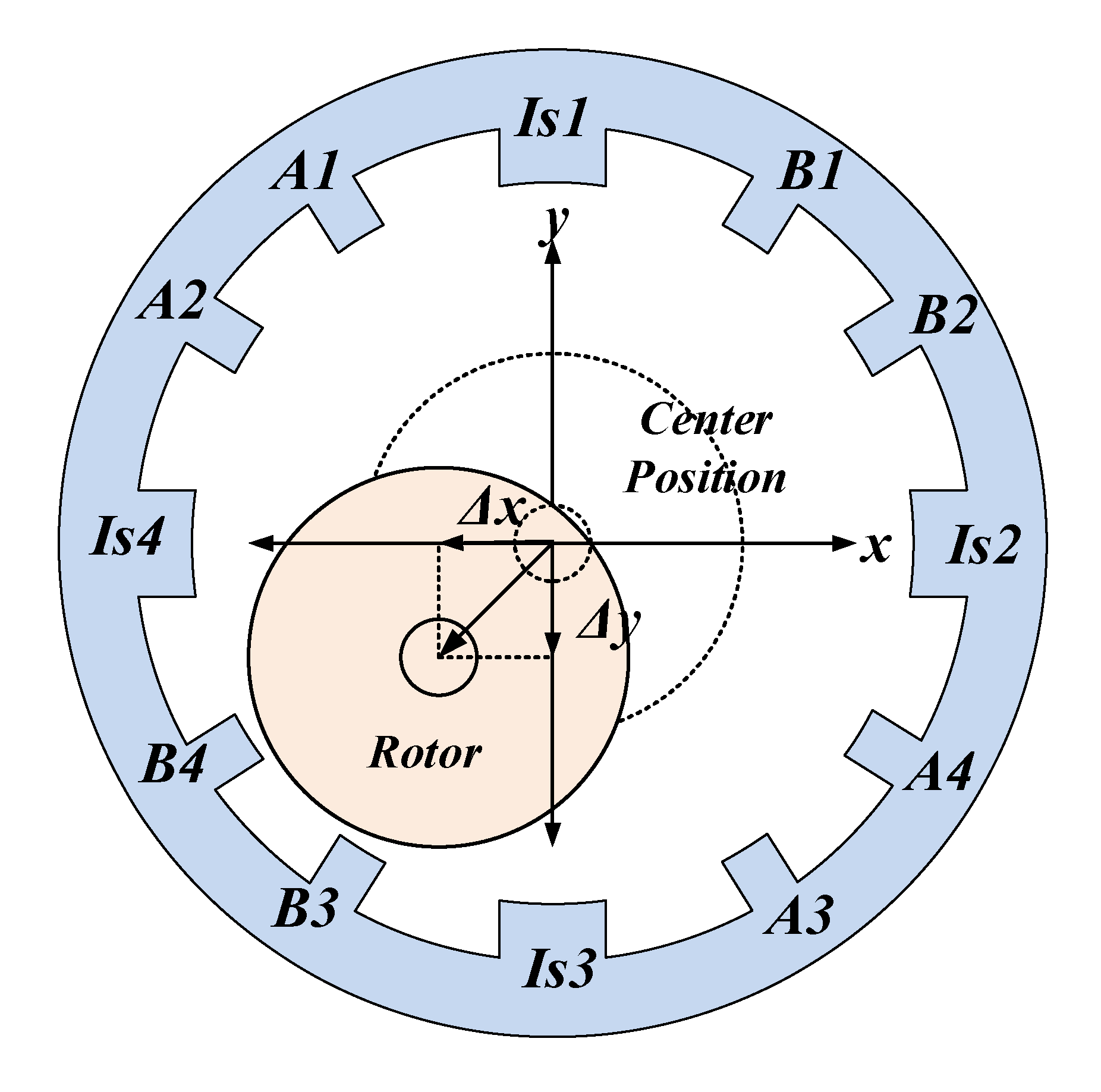
The stator and the rotor of the BSRM consist of salient poles. There are two types of windings on the stator—one is the suspension force winding to produce suspension force, and the other is torque winding to produce the reluctance torque. There are no windings on the rotor. The regulated DC voltages are applied to the stator torque coils and suspension coils individually to achieve decoupled performance among net radial suspension force and resultant torque. The coordinately placed suspension winding coils Is1 and Is3, and Is2 and Is4 on the stator produces the radial forces in Y and X directions, respectively. Is2 and Is1 produce the positive suspension forces, and Is4 and Is3 poles produce the negative suspension forces to make uniform and equilibrium stable levitation action. The remaining stator main-phase coils, known as Phase-A and Phase-B, will produce the resultant rotational torque. The operating parameters and ratings of the 12/14 BSRM are given in Table 2.
The basic 12/14 BSRM construction and its winding arrangement is shown in Figure 1.

2.1. FEM Analysis

In switched reluctance machines, the motor torque profile is always in a nonlinear relationship to the operating current and rotor position due to its switching operation [41,42,43]. At present, FEM-based simulations offer the best accurate machine models. The FEM numerical data can be used directly in any controller and observer designs [44,45].
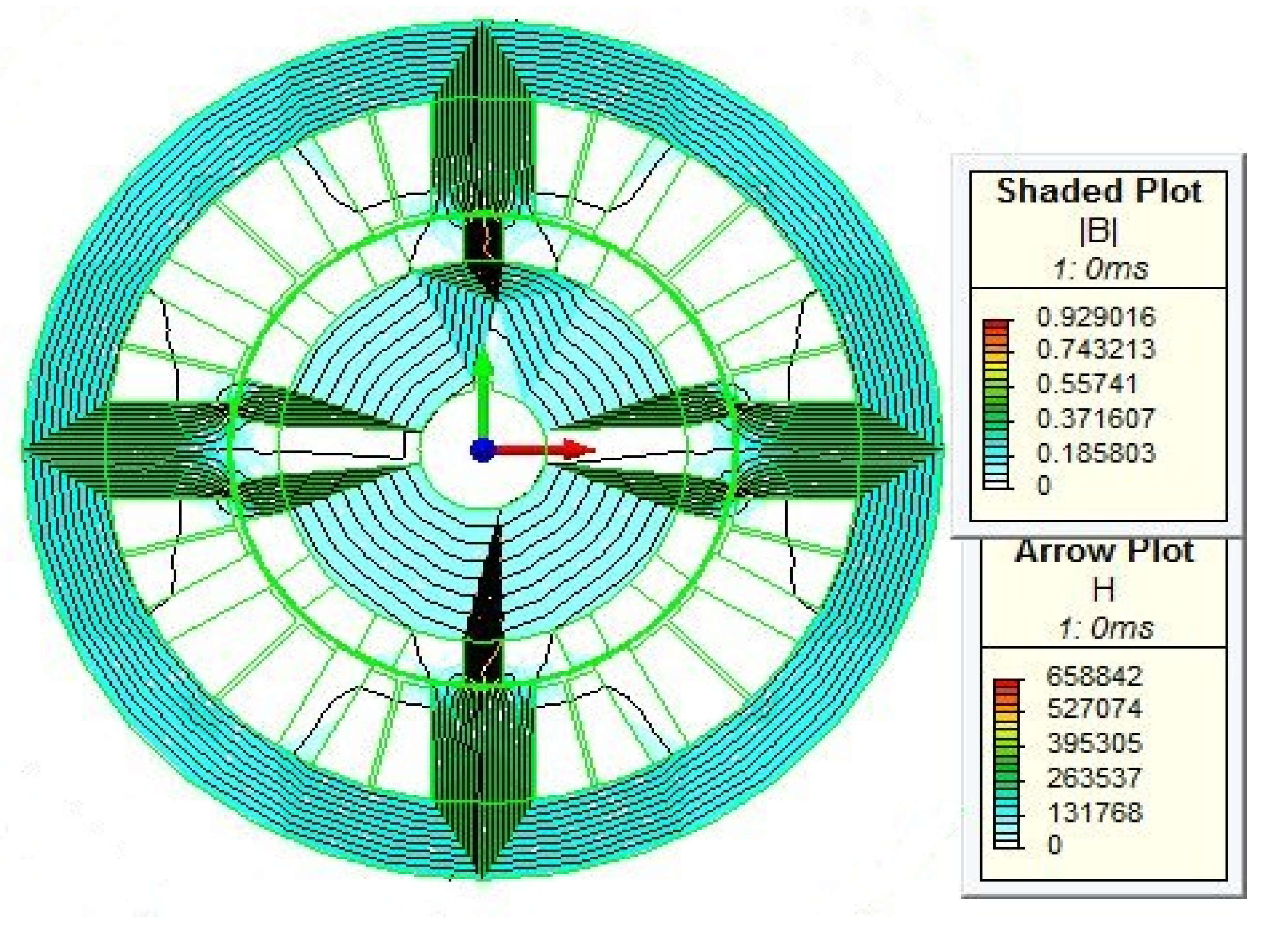
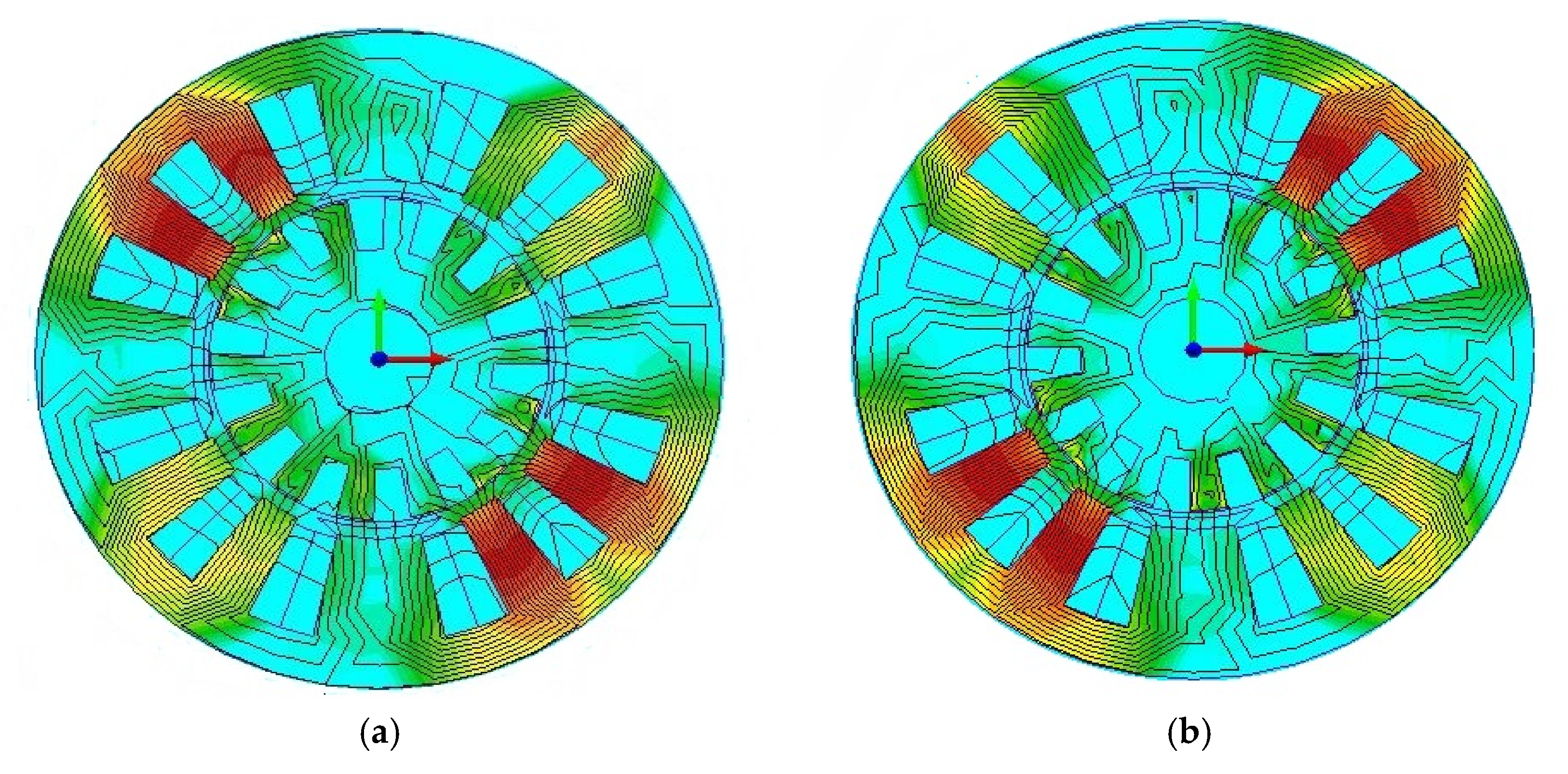
The suspension winding’s flux pattern, when all the coils are excited, is shown in Figure 2. Similarly, the individual flux distribution pattern of the main windings is shown in Figure 3a,b.
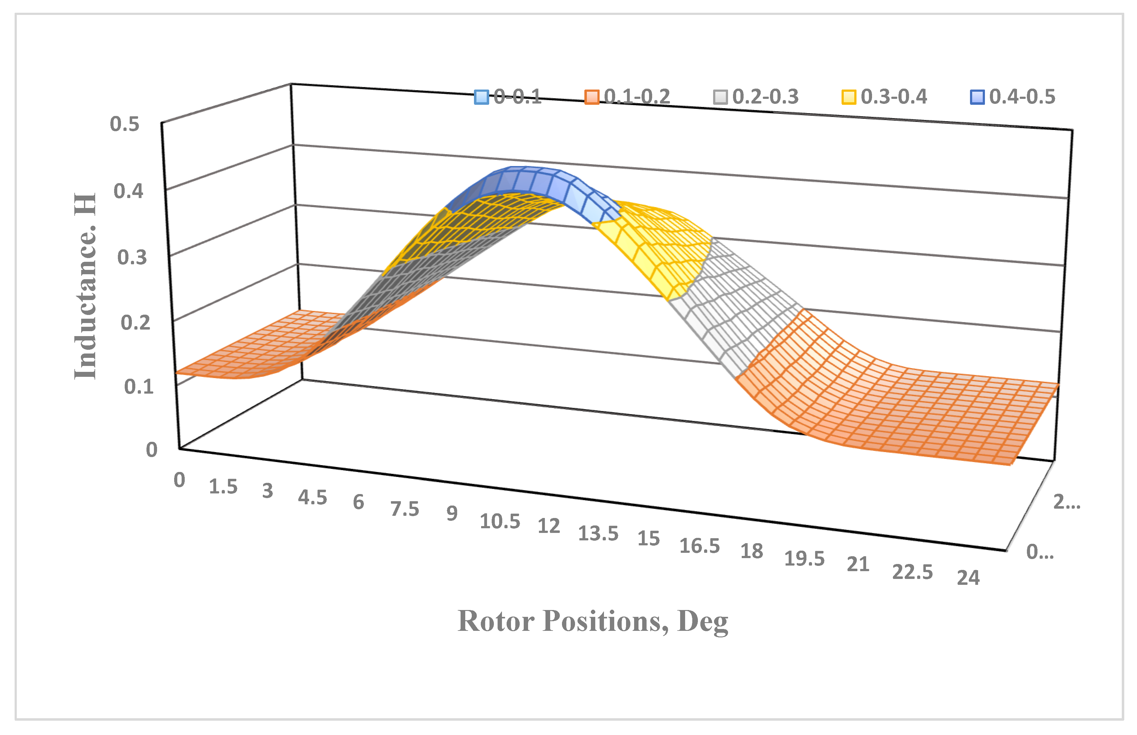
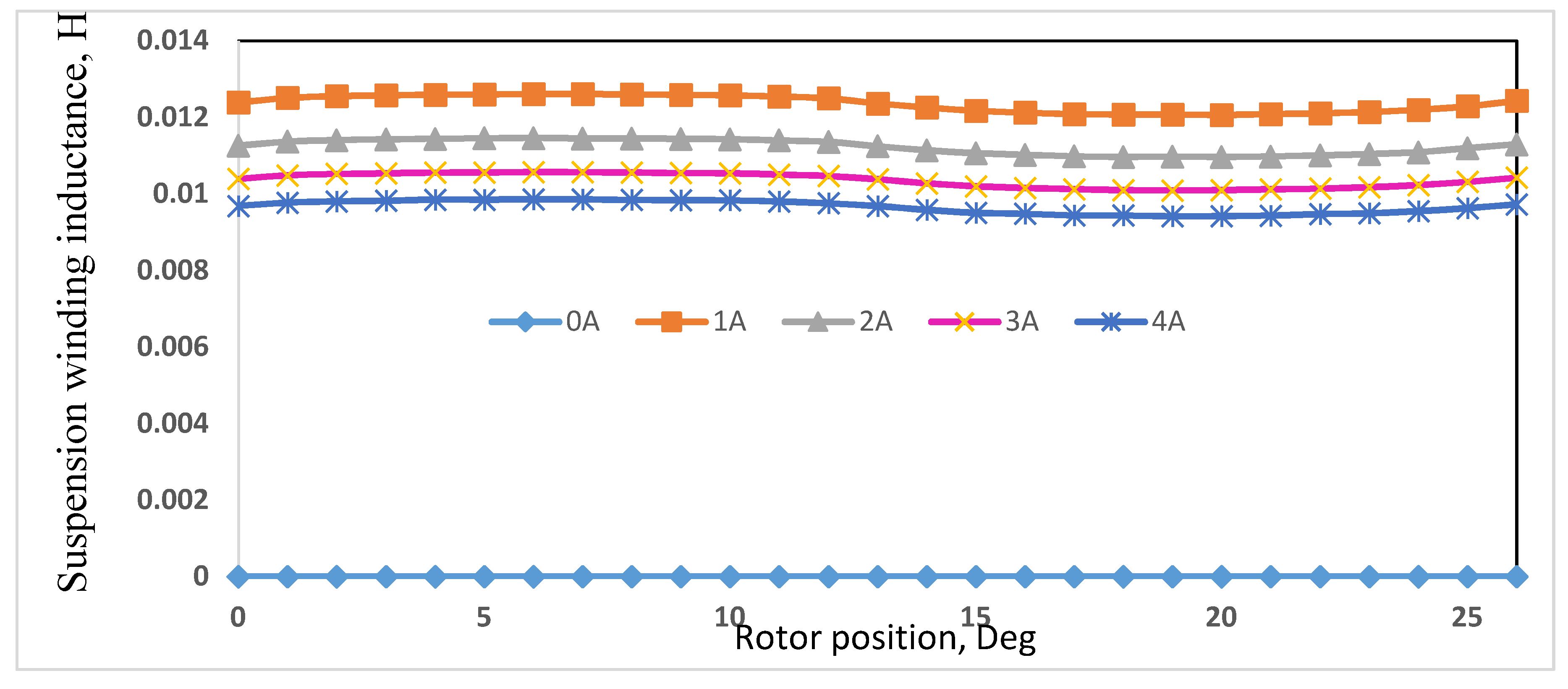
The short flux paths in the stator core reduce core losses, and therefore there is less requirement of magneto motive force (MMF). The main torque winding and suspension winding inductance values are shown in Figure 4 and Figure 5 at different current values. As shown in Figure 4, the main torque-winding inductance varies with rotor positions, which reaches its maximum value when the rotor and stator poles overlap position.
Similarly, as shown in Figure 5, due to the pole arc of the suspension pole being more significant than one rotor pole pitch, the inductance profile of the suspension winding is almost constant, and it does not vary with rotor position.
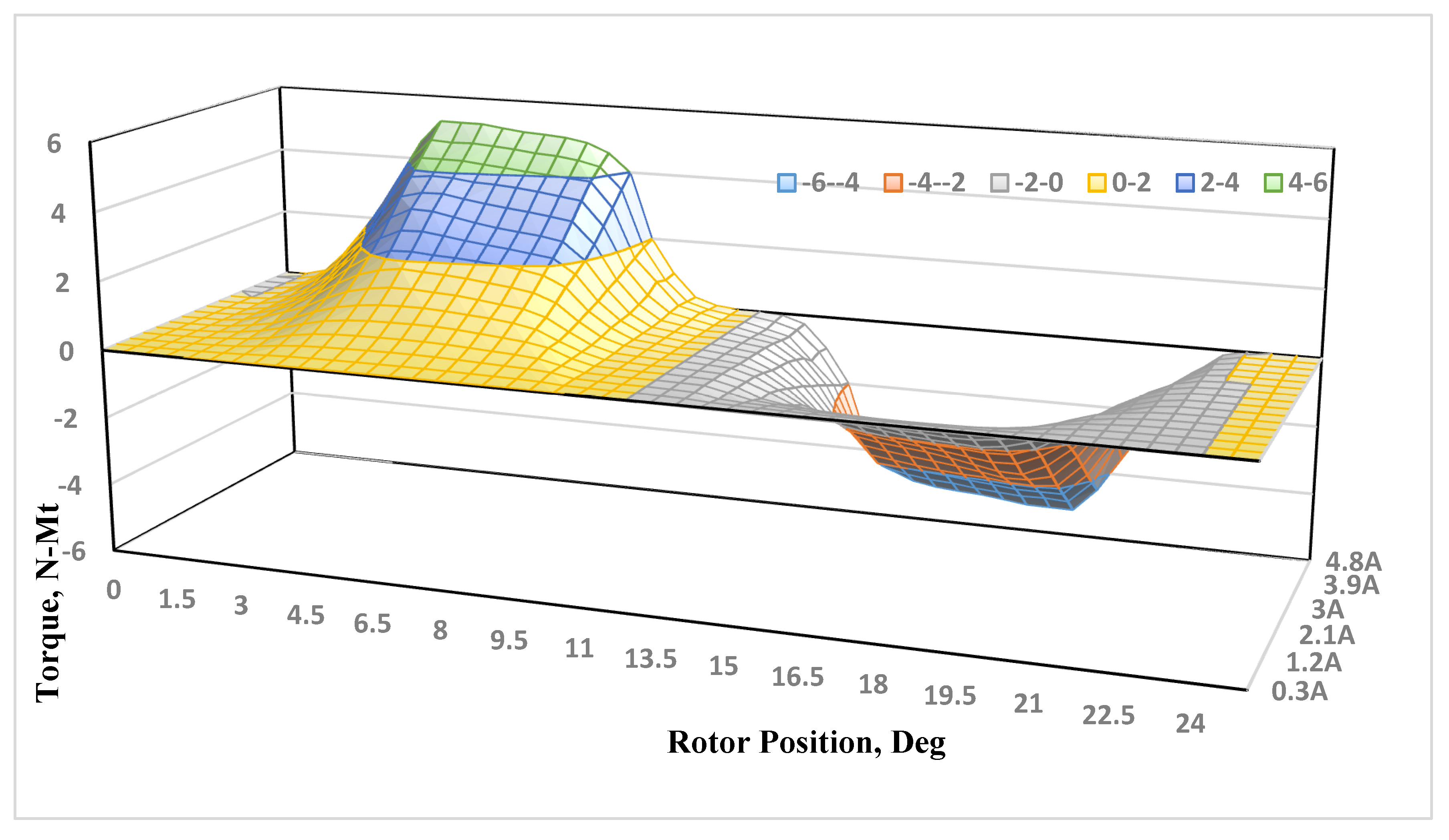
The main torque profiles of BSRM regarding rotor position and at different phase current values shows the nonlinear relationship between torque and phase currents, as shown in Figure 6.

2.2. Rotor Modeling (Suspension Control)

To levitate the rotor from a standstill position, the total suspension force (Fs) is obtained by adding both x- and y-directional suspension forces, given in Equation (1).
F s = F x + F y
F s = m   [ d 2 x dt 2 + d 2 y dt 2 ] + [ k x + k y ] + m g
The desired rotor displacement tracking states are written and shown in Equation (3) by choosing displacement states X1, X2, Y1, and Y2 as state variables from Equations (1) and (2).
x ˙ 1 = x 2   y ˙ 1 = y 2 x · 2 = k x m X 1 + F x m + F dx ,   y ˙ 2 = k y m Y + F y m + F dy + g
The electrical equivalent suspension forces in terms of suspension currents are given by Equation (4).
[ F x F y ] = [ K xxp K xyp K xxn K xyn K yxp K yyp K yxn K yyn ] [ i xp 2 i yp 2 i xn 2 i xn 2 ]
By equating the above Equations (3) and (4), Equations (5) and (6) are obtained.
F x = m d 2 x d t 2 + k x = [ K X ] [ I x ]
F y = m d 2 y d t 2 + k y + m g = [ K Y ] [ I Y ]
where K X = diag [ Kxxp Kxyp Kxxn kxyn ] , K Y = diag [ K yxp K yyp K yxn K yyn ] , and I x = [ I x p 2 I x n 2 ] , I Y = [ I y p 2 I y n 2 ]
For the rotor displacements, the equivalent desired tracking state–space equations are given by
[ x 1 · x 2 · y 1 · y 2 · ] = [ 1 0 0 0 k m 0 0 0 0 0 1 0 0 0 k m g 0 ] [ x 1 x 2 y 1 y 2 ] + [ 0 0 0 0 Kxxp Kxyp Kxxn Kxyn 0 0 0 0 Kyxp Kyyp Kyxn Kyyn ] × [ i xp 2 i yp 2 i xn 2 i xn 2 ]

2.3. Modeling of BSRM for Motor Control

The motor states Ψph, w, and θ are considered to be state variables for the state–space representation of BSRM, as shown in Equation (8).
d ψ ph dt = R ph N ( θ ) ψ ph + V ph + w ψ d w dt = T e T l J B J w + T e J + w w d θ dt = w + w θ I ph = N ( θ ) ψ ph }

2.4. Switching Control Strategy

The BSRM needs six hysteresis current controllers overall to controlling both suspension force and net torque. Out of six, two are for individual torque-winding current controllers and the remaining four are for suspension force current controllers. According to the operating principle discussed in the above section, the six-phase 12/14 BSRM needs 12 power switches. As a result, eight power switches are essential for controlling the four-phase suspension windings and four power switches for two-phase torque windings.
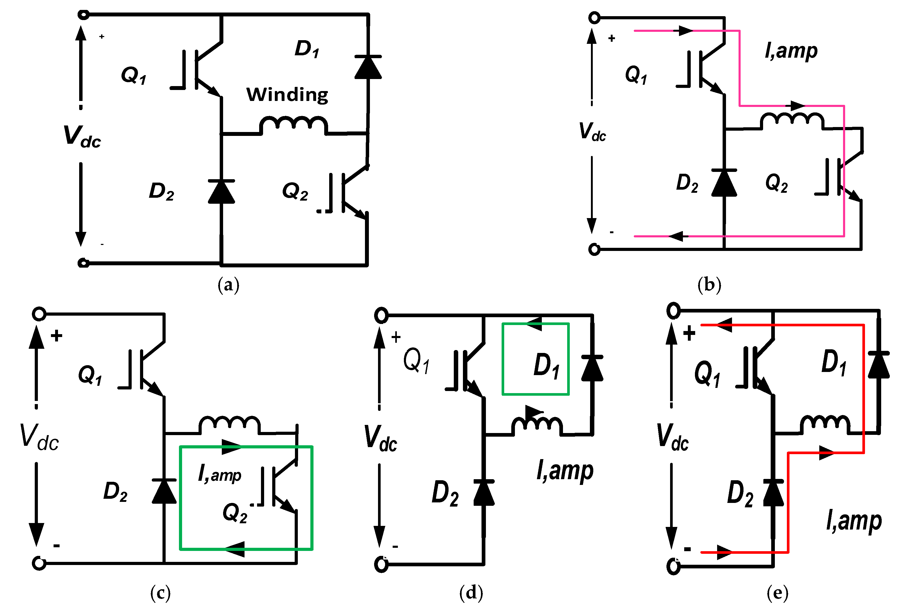
Figure 7 shows the four switching states of the asymmetric converter, which are used in BSRM for independent control of each phase. Mode 1 is a magnetization mode in which positive DC-link voltage is applied to the winding; Modes 2 and 3 are freewheeling modes in which the winding has short-circuited through an IGBT and a diode; Mode 4 is a demagnetization mode where the negative DC-link voltage is applied.
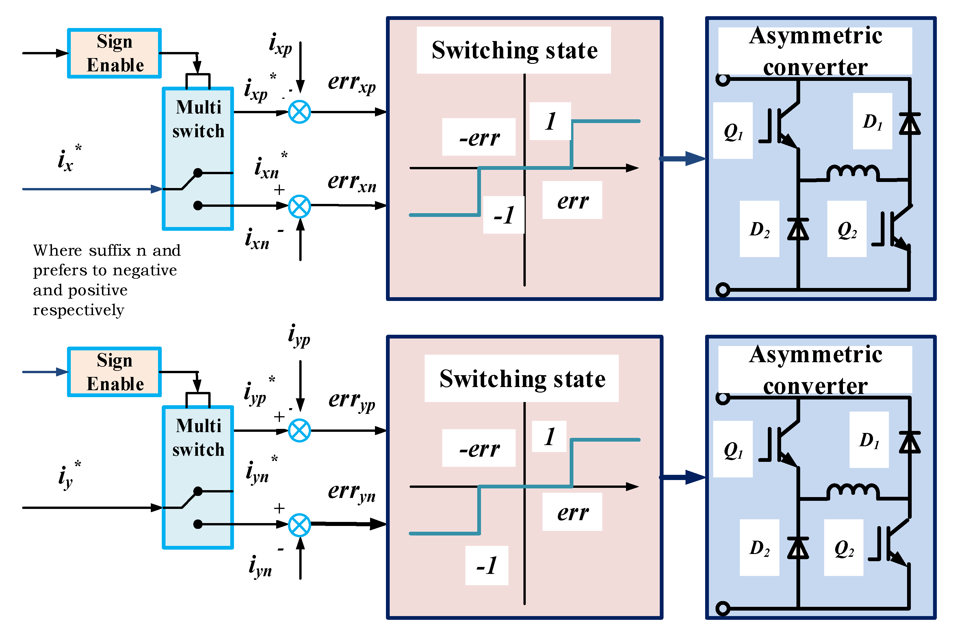
The selection of suspended force windings is mentioned in Table 3, where the switching state 1 indicates magnetization mode; the switching state 0 means freewheeling mode. Figure 8 shows the switching block diagram of suspension control.

3. Modeling of Global Sliding-Mode Controller

The rotor displacement error functions and new global sliding-mode switching equations are expressed by Equations (9) and (10).
e x = x x d ,   e y = y y d
S x = e · x + C x S x S x ( 0 ) e D x t   C x ˃ 0
S y = e · y + C y S y S y ( 0 ) e D y t   C y ˃ 0
The derived GSMC equations for rotor displacements are given by
U x = J x new ( C x x 2 f x . ( t ) ) + J x new ( x . d + C x x d ) ( Δ J x new | C x x f x . ( t ) | + Δ J x | x . d + C x x d | ) sgn ( s x )
U y = J y new ( C y y 2 f y . ( t ) ) + J y new ( y . d + C y y d ) ( Δ J y new | C y y fy . ( t ) | + Δ J y | y . d + C y y d | ) sgn ( s y )
Similarly, the motor speed tracking error function, the new global sliding-mode switching function for speed tracking and control equations are defined by Equations (14)–(16).
e w = w w d ,   e ˙ w = w ˙ w ˙ d
S w = x · w + C w e w S w ( 0 ) e kt C w ˃ 0
U w = J new ( C w w f . ( t ) ) + J new ( w . d + C w w d ) ( Δ J new | C w w f . ( t ) | + Δ J | w . d + C w w d | ) sgn ( s w )
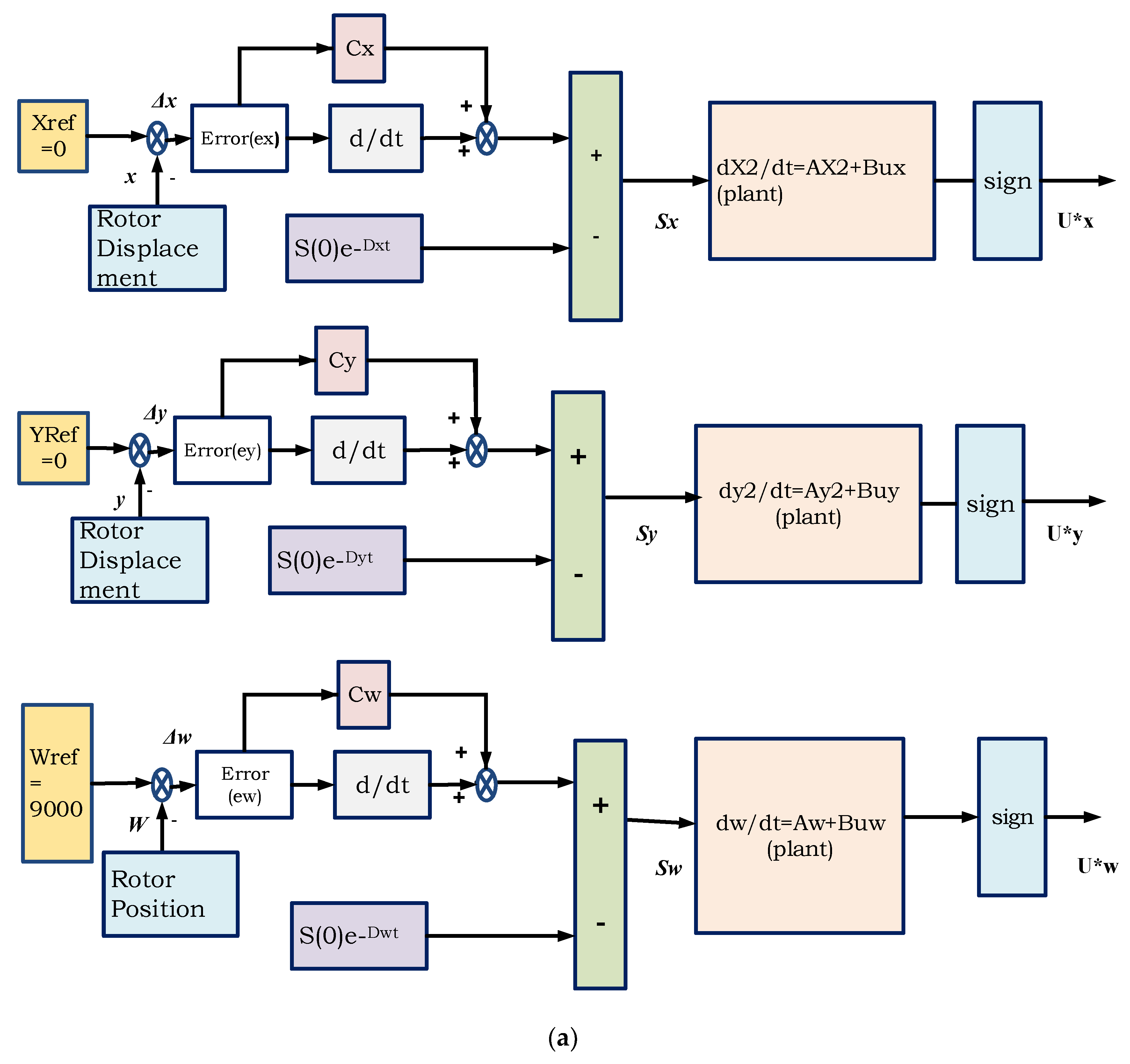
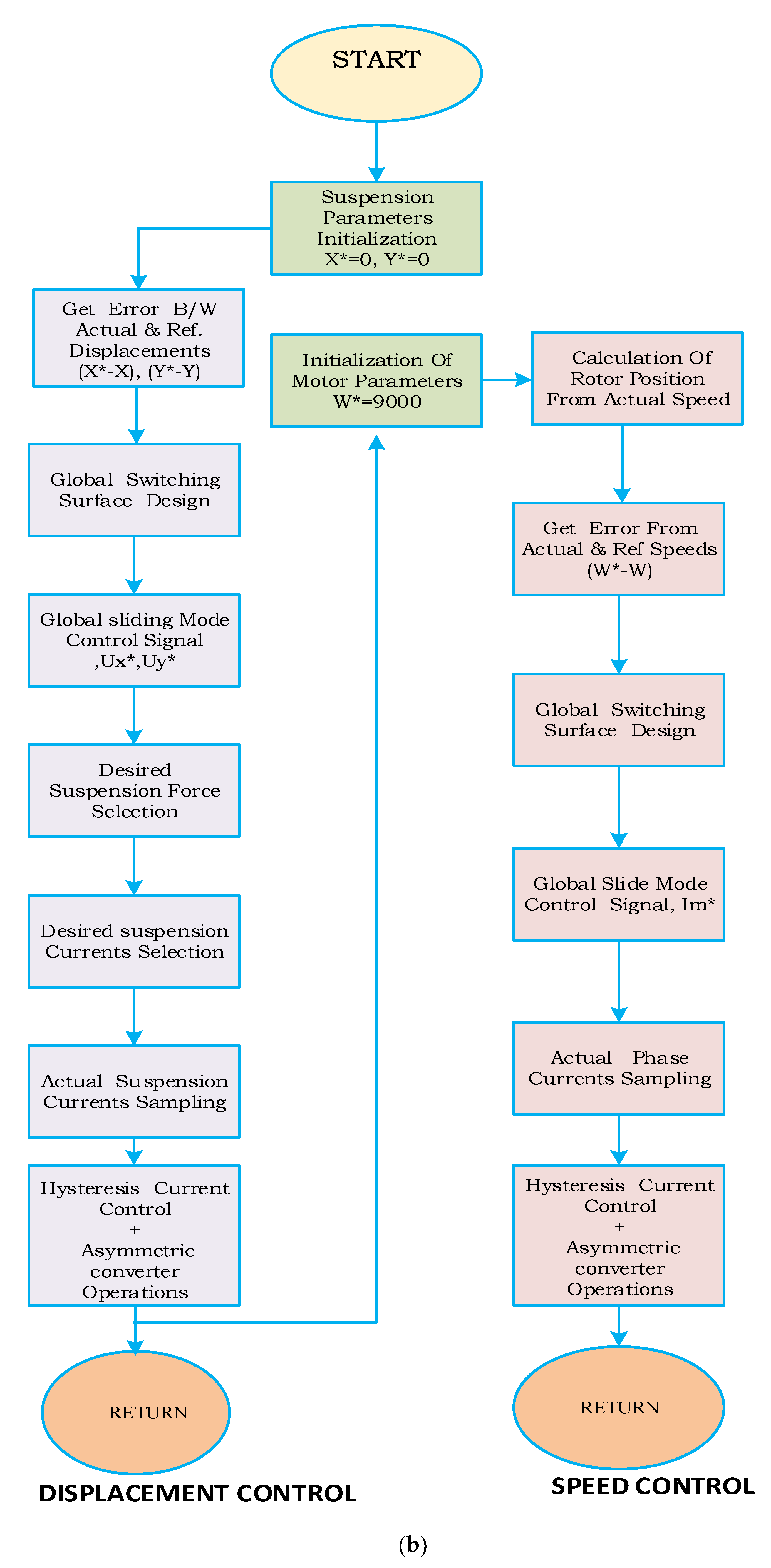
The design and implementation procedure of GSMC are shown in Figure 9. The simple block diagram and the stepwise procedure of GSMC-based control of BSRM are shown in Figure 9a,b, respectively.
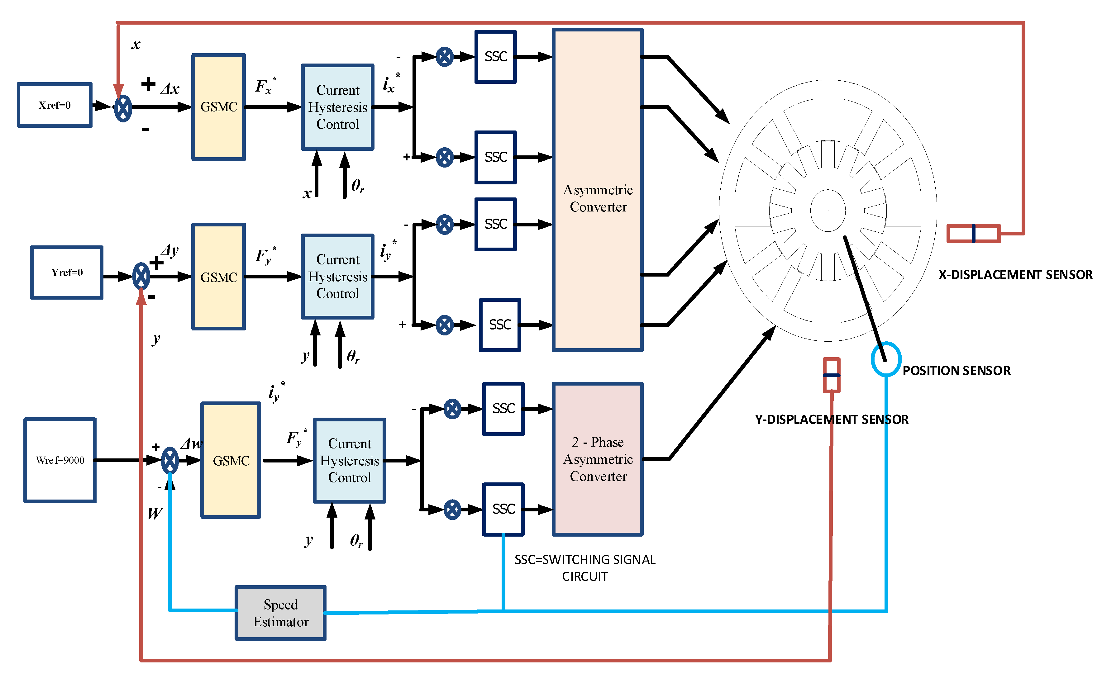
The complete sensor-based eccentric control block diagram of BSRM is presented in Figure 10. The actual rotor X and Y displacements are taken as feedback from displacement sensors and are added negatively to the reference displacements (Xref = 0 and Yref = 0). The controlled outputs Fx* and Fy* are produced from the GSMC controller according to the given displacement error signal. The controlled forces are then applied to the current hysteresis controller, which generates eight suitable switching signals to the four-phase asymmetric converter. The four-phase suspension asymmetric converters excite the suspension windings with controlled phase voltages. The resultant suspension phase currents produce the suspension force to levitate the rotor to the desired location.

4. Results and Discussions

4.1. Levitation Control of BSRM

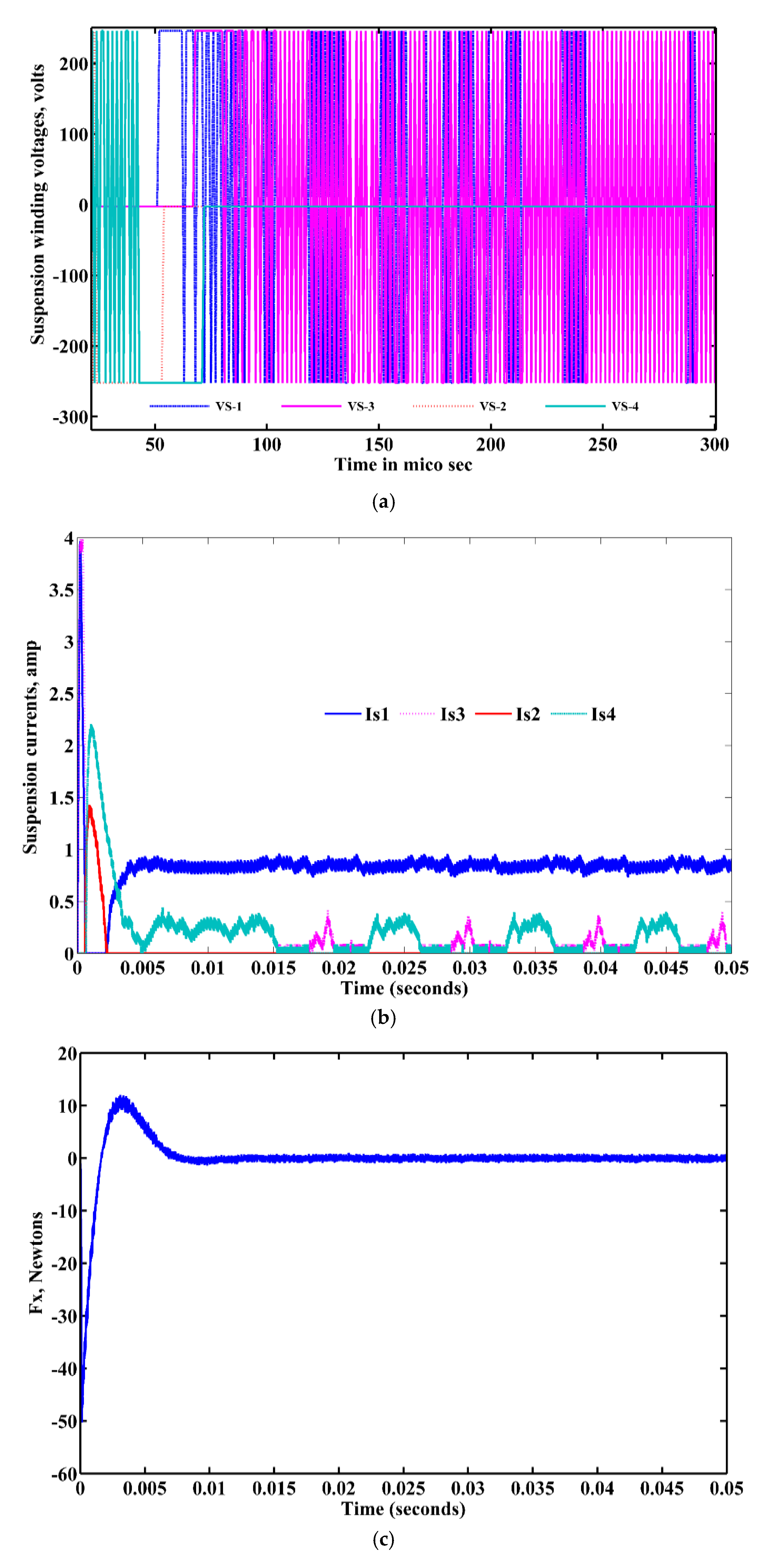
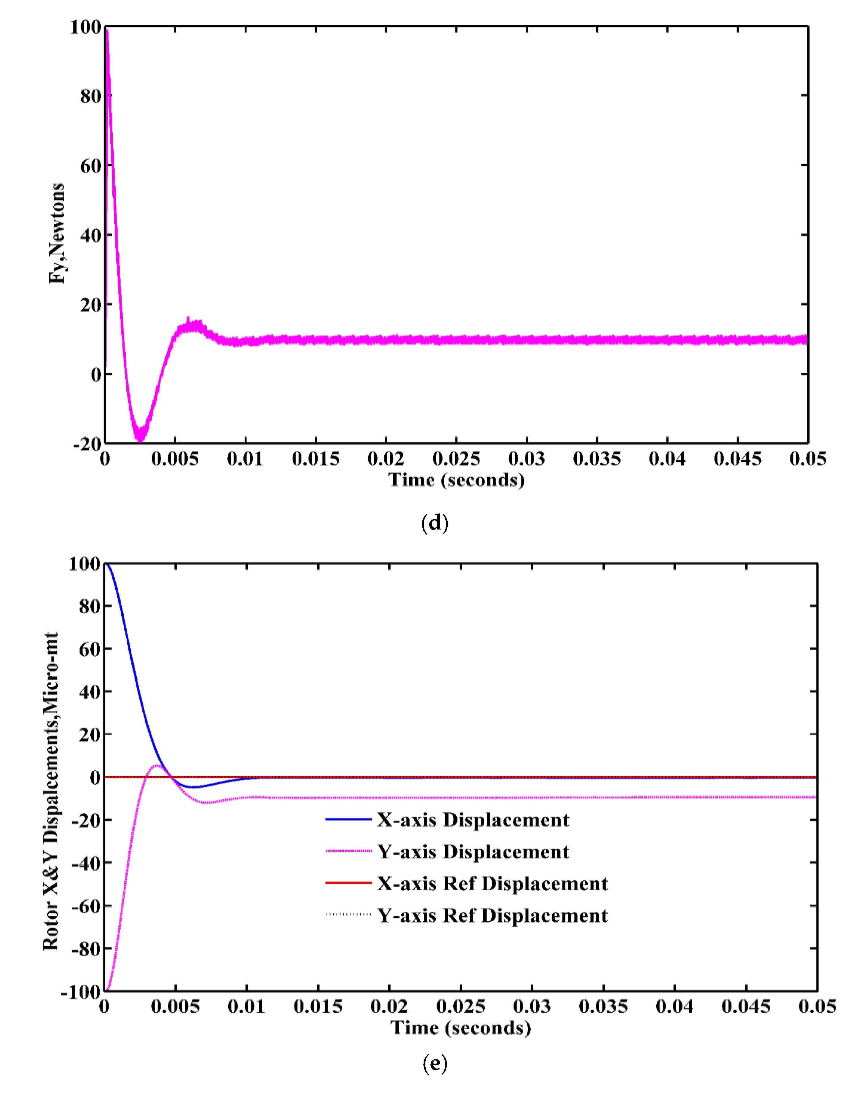
In accordance with the switching state instructions of the hysteresis current controller, the stator suspending force winding currents Is1, Is2, Is3, and Is4 produce the controlled levitation forces to keep the rotor at the center when the rotor is displaced by −100 and +100 micrometers in x and y directions, respectively, from the origin. The suspension-controlled voltages and currents are presented in Figure 11a,b, respectively. At the time of starting of the motor, the suspension windings draw maximum currents to overcome their own inertia of the rotor weight. The net levitation forces and actual displacements of the rotor are presented in Figure 11c–e. Figure 11e shows that the eccentric displacement errors in two directions quickly come to zero, which implies that if the rotor is in any of the four quadrants, the proposed GSMC suspension controller will put the rotor at the center position in less than 0.01 s.

4.2. Accelerating the Rotor to the Desired Speed

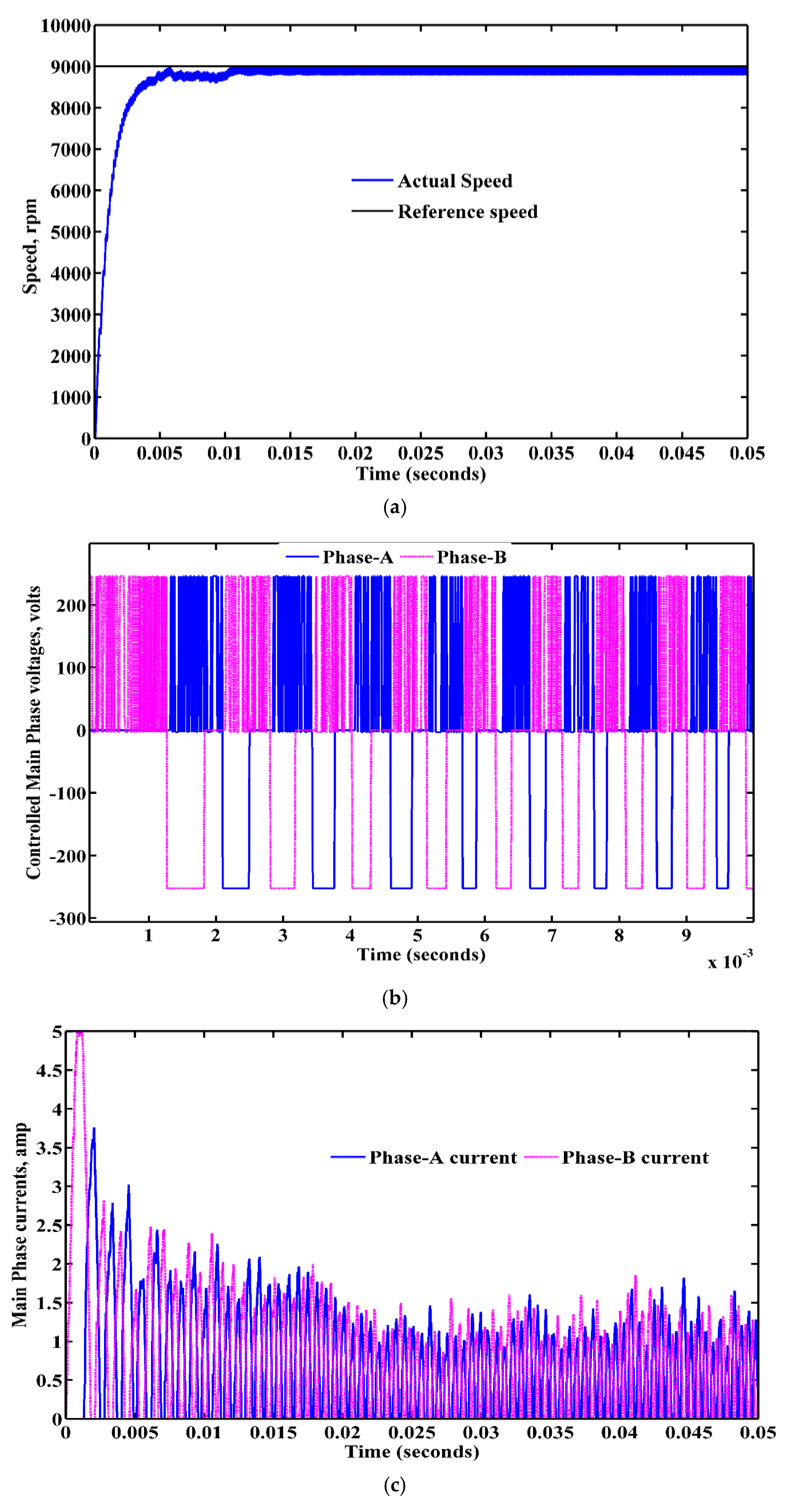
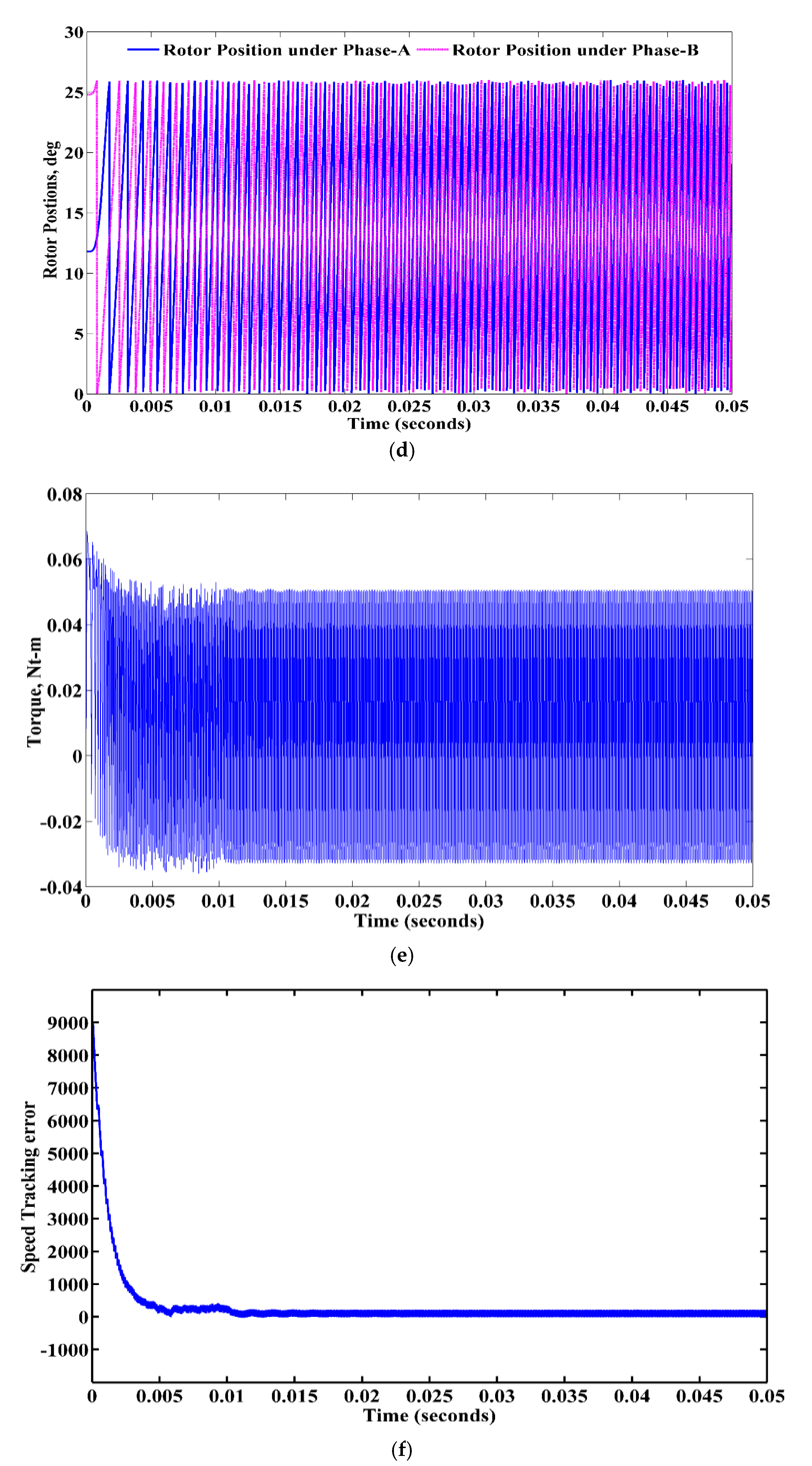
The BSRM operates in a single pulse mode, which means the only positive voltage is excited at conduction (magnetization) mode. Similarly, the reverse voltage is excited at the time of the demagnetization mode. From Figure 12a, it can be observed that the process of getting the desired speed of 9000 rpm on the 12/14 BSRM is same as that of general SRM. The output torque phase currents seem to be steady, and the torque currents show practically very little effect on the suspending force, as shown in Figure 12b–d when the steadily suspended rotor rotates at 9000 rpm at the center position. From Figure 12e, the ripples in the net output torque are comparatively more since here no optimal methods are used to reduce the ripples in actual torque. The sliding-mode speed trajectory is shown in Figure 12f.

4.3. Robust Behavior of Rotor under Different Loads and Changes of Parameters

4.3.1. Variation of Suspension Loads

When the rotor is initially placed in any of the four quadrants, to observe and confirm the robustness and fast-tracking control properties of the proposed GSMC to the BSRM, different loads and parameter variation cases are considered. Before applying the suspension loads, the rotor is initially placed at an eccentric distance of (±100 μm, ±100 μm) and the reference displacements of (0, 0) are kept at origin, respectively.
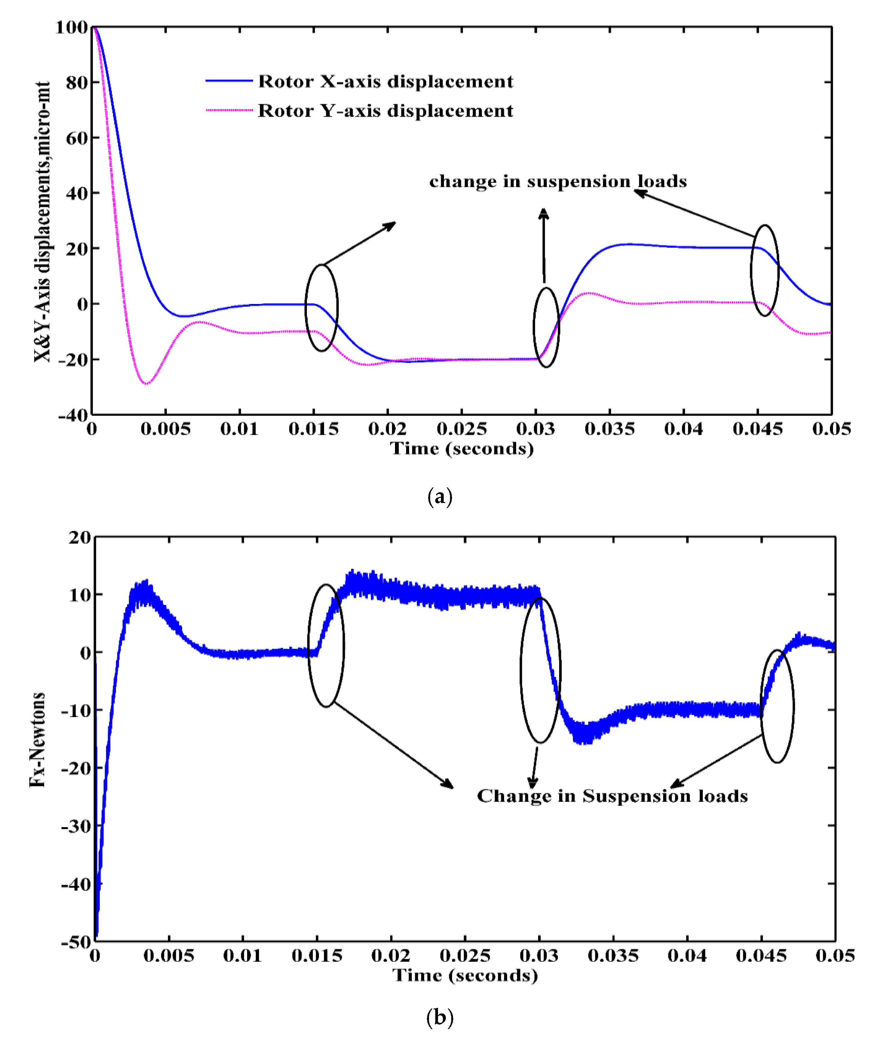
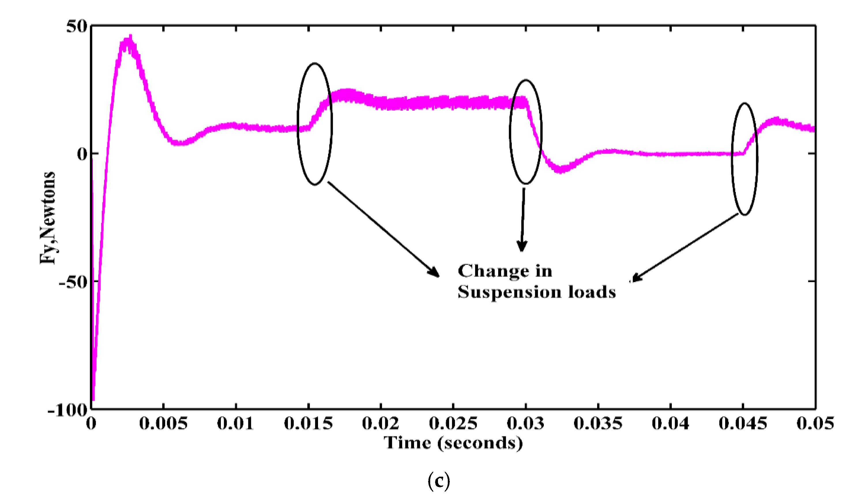
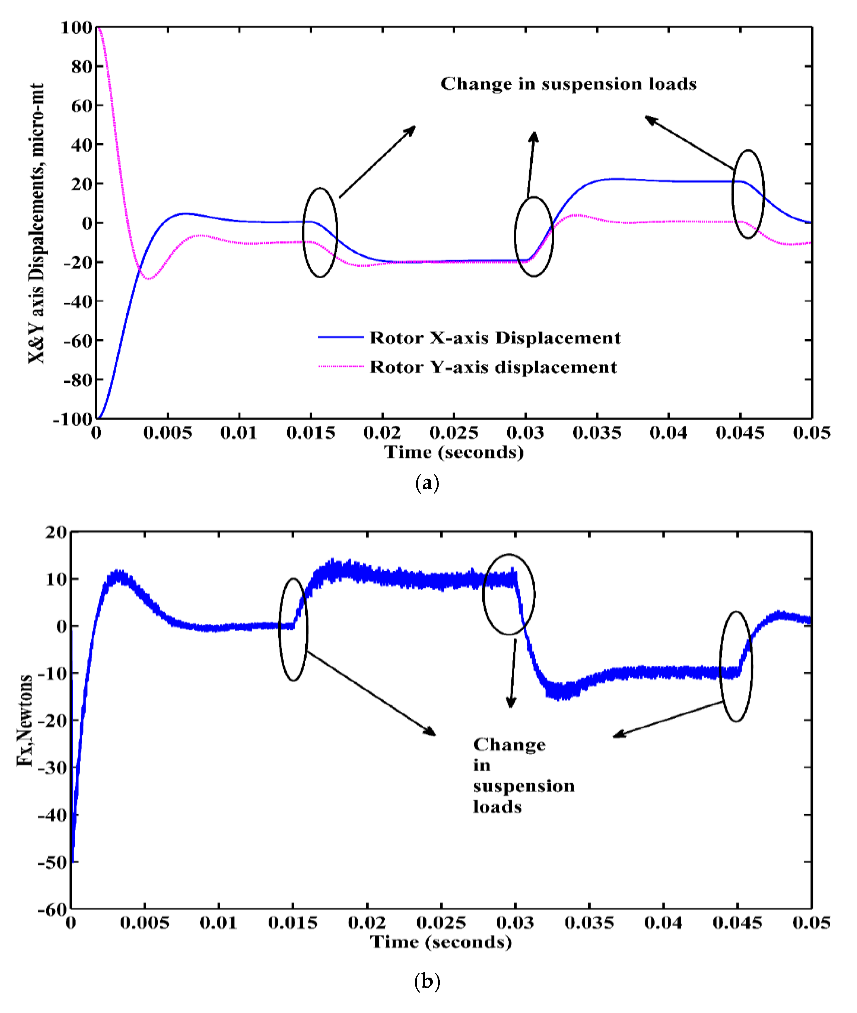
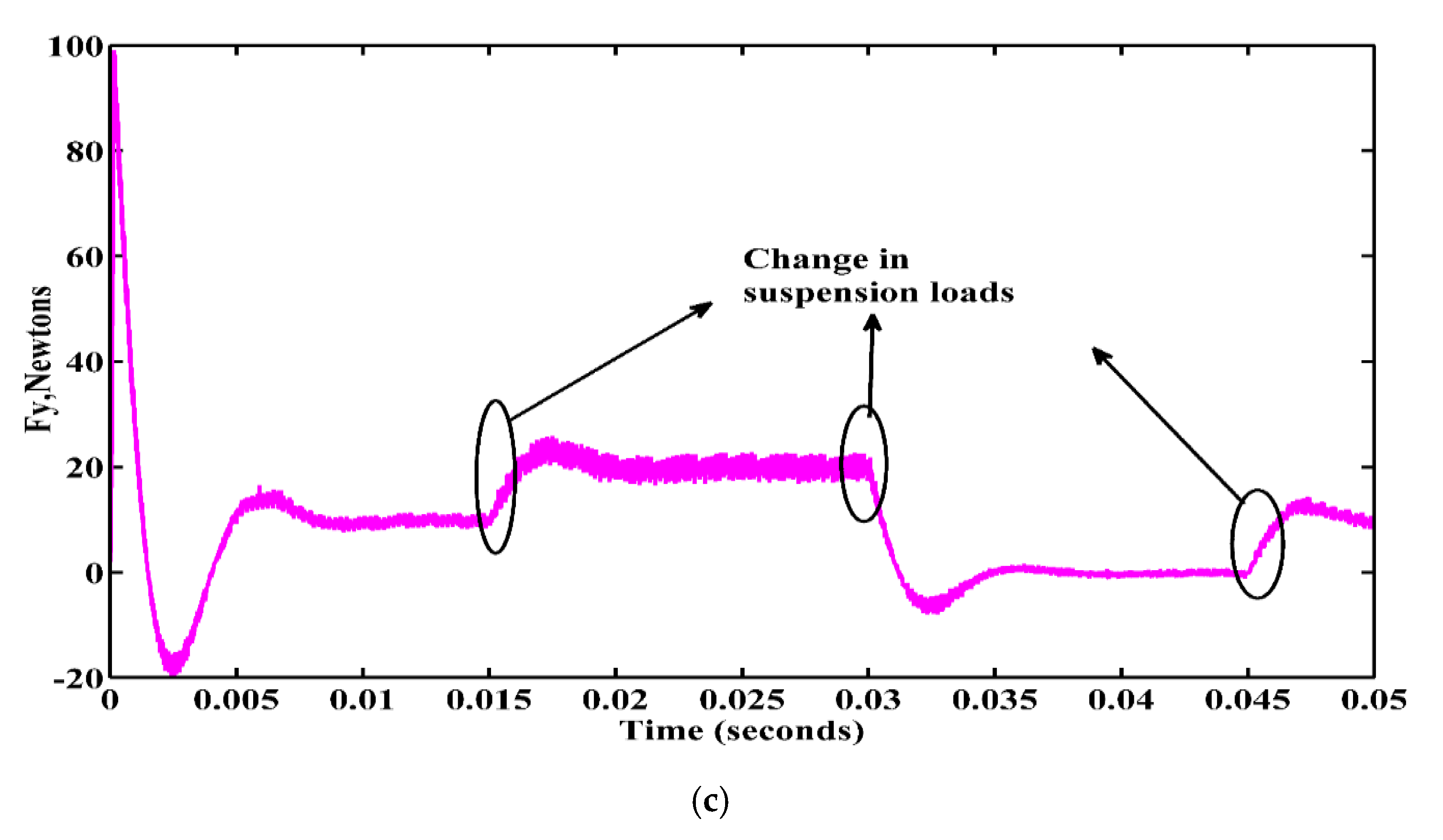
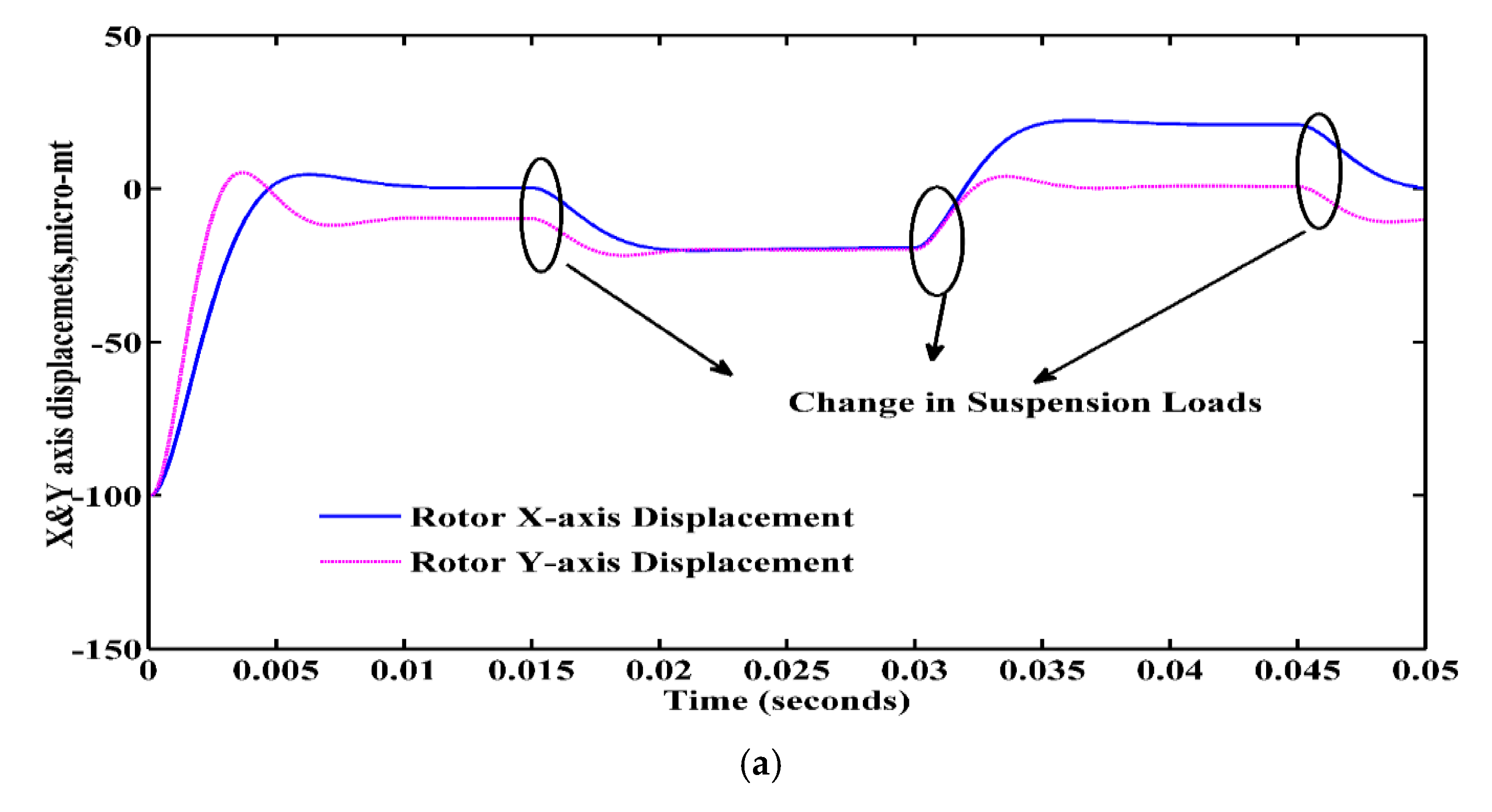
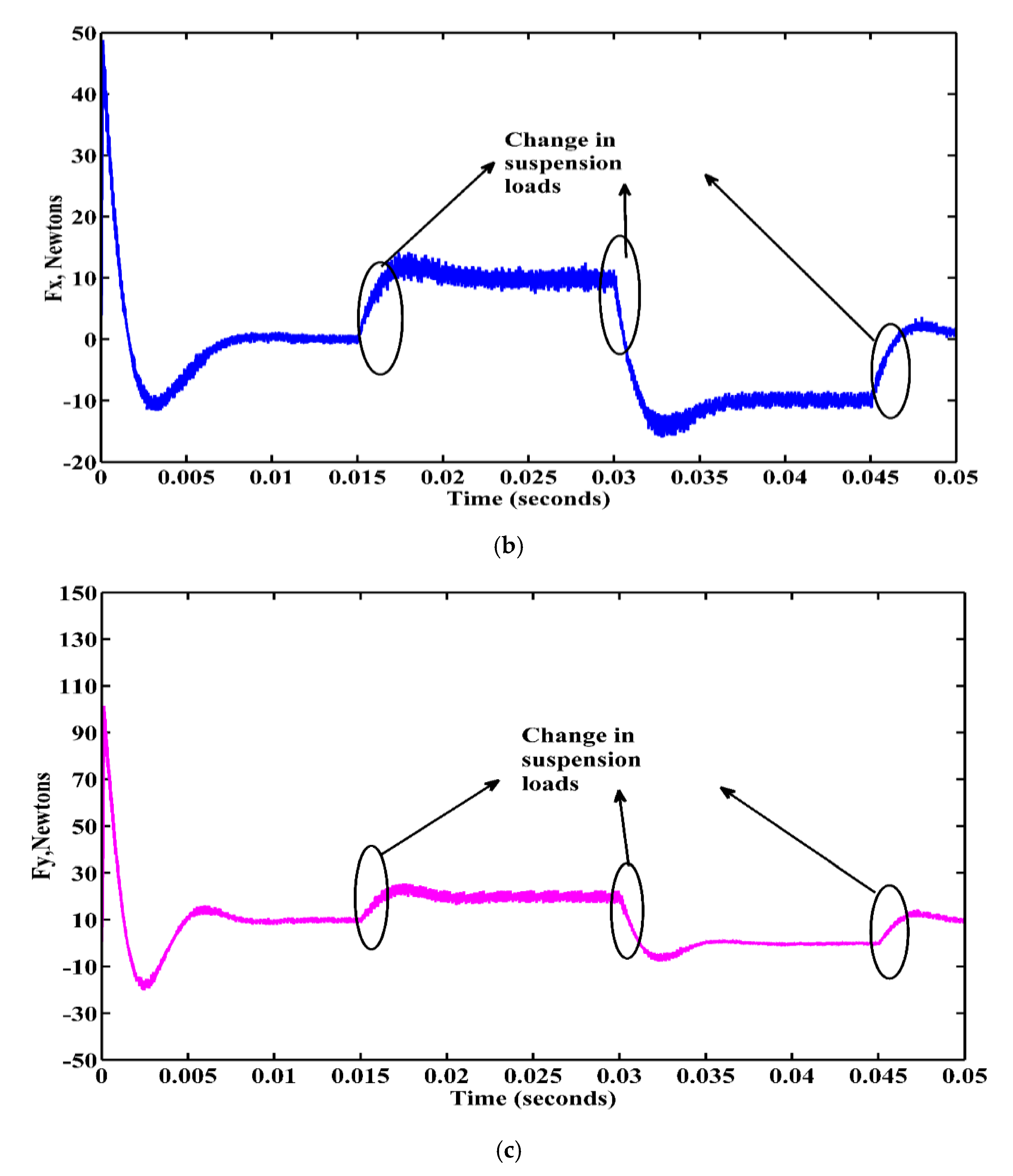
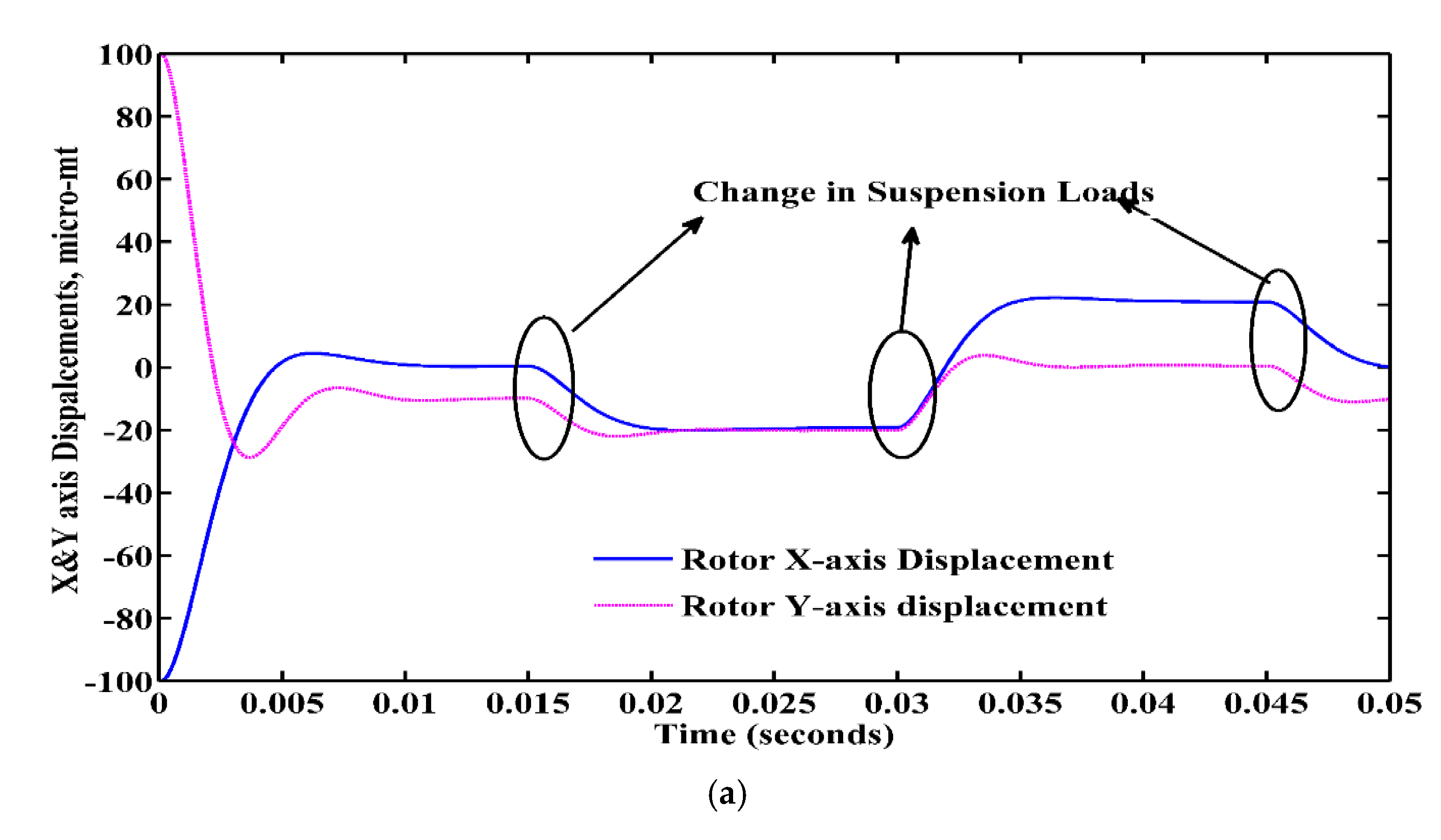
The displacements of rotor and the overall suspension forces both in X and Y directions are presented in Figure 13a–c, when the rotor is initially placed in the first quadrant (+100 μm, +100 μm) and subjected to a suspension load disturbances of 10 N at 0.015 s, −10 N at 0.03 s, and 0 N at 0.045 s in both X- and Y-axis, respectively. Similarly, the suspension forces and rotor displacements are shown in Figure 14a–c, when the rotor is placed in an eccentric distance off (+100 μm, −100 μm) from the origin, i.e., in the second quadrant, and subjected to suspension loads.
Figure 15a–c and Figure 16a–c show the rotor suspension forces and displacements when the rotor is in the third and fourth quadrants when the rotor is subjected to suspension loads. From the results, it is observed that the proposed suspension controller rapidly tracks the rotor displacements and positions, and keeps the rotor in the center due to its robust response to external forces.

4.3.2. Change of Input Reference Displacements

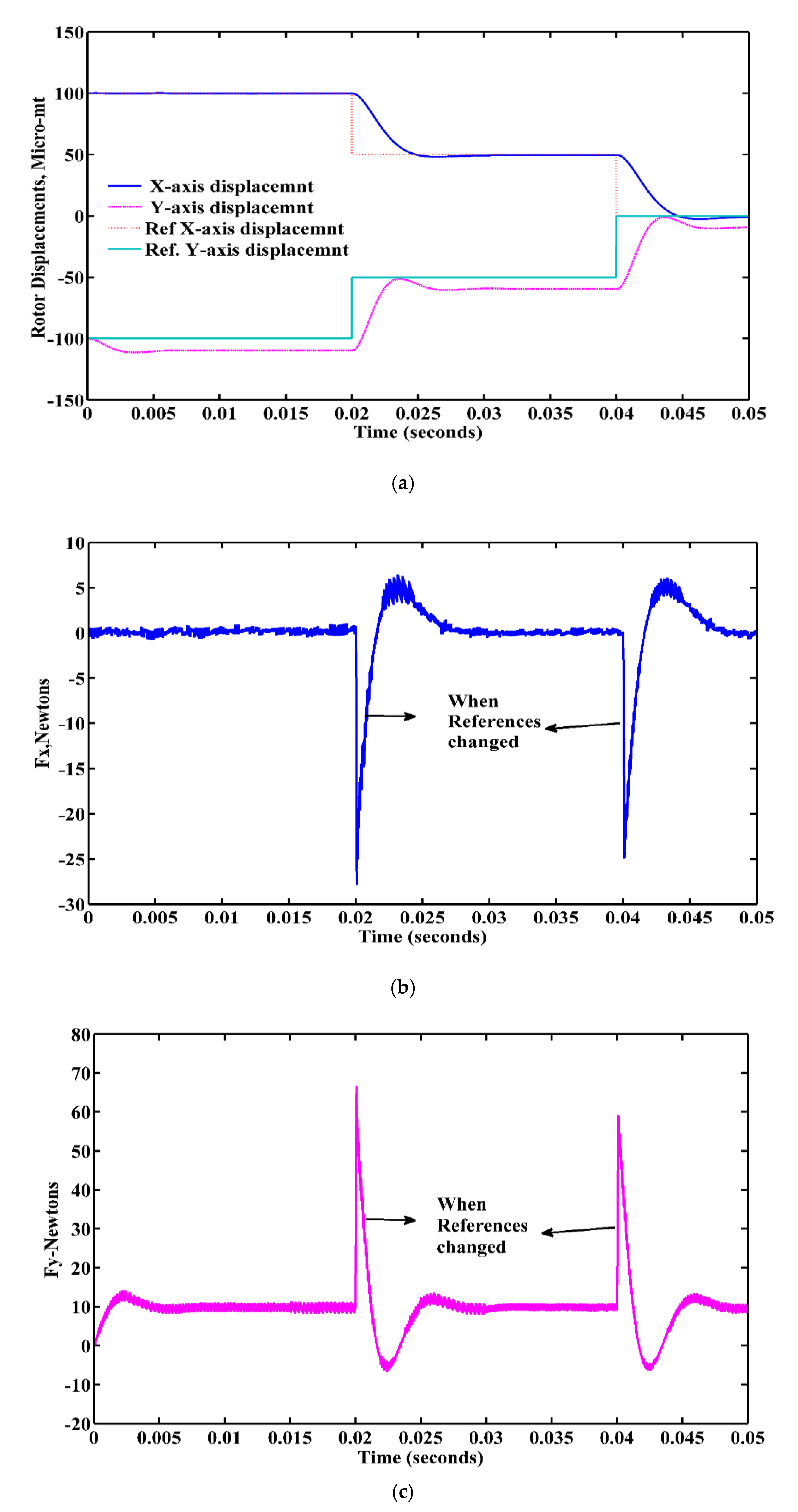
In this section, the study of the rotor response to the reference command input, its performance characteristics, and the stable levitation properties of a suspended rotor in all quadrants are carried out. The large change in reference value makes a large error input signal to the controller. Therefore, reference values are changed in all four quadrants when the rotor is placed initially at an eccentric physical distance of (+100 μm, −100 μm) in both X and Y directions from the origin, respectively. The simple eccentric displacement of the rotor from the center position is displayed in Figure 17.
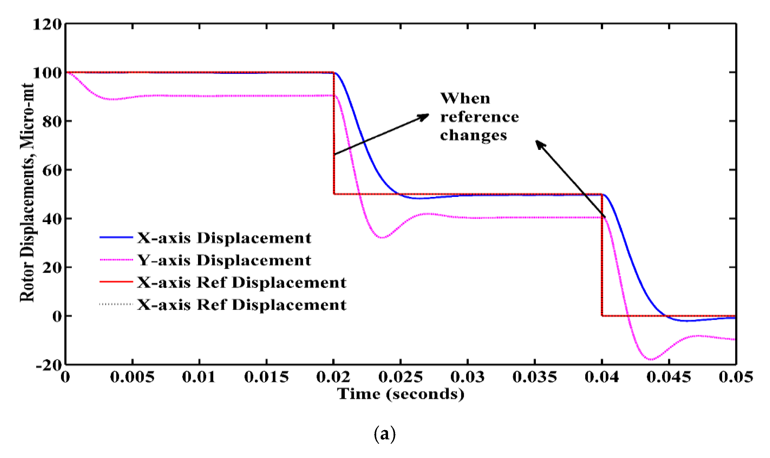
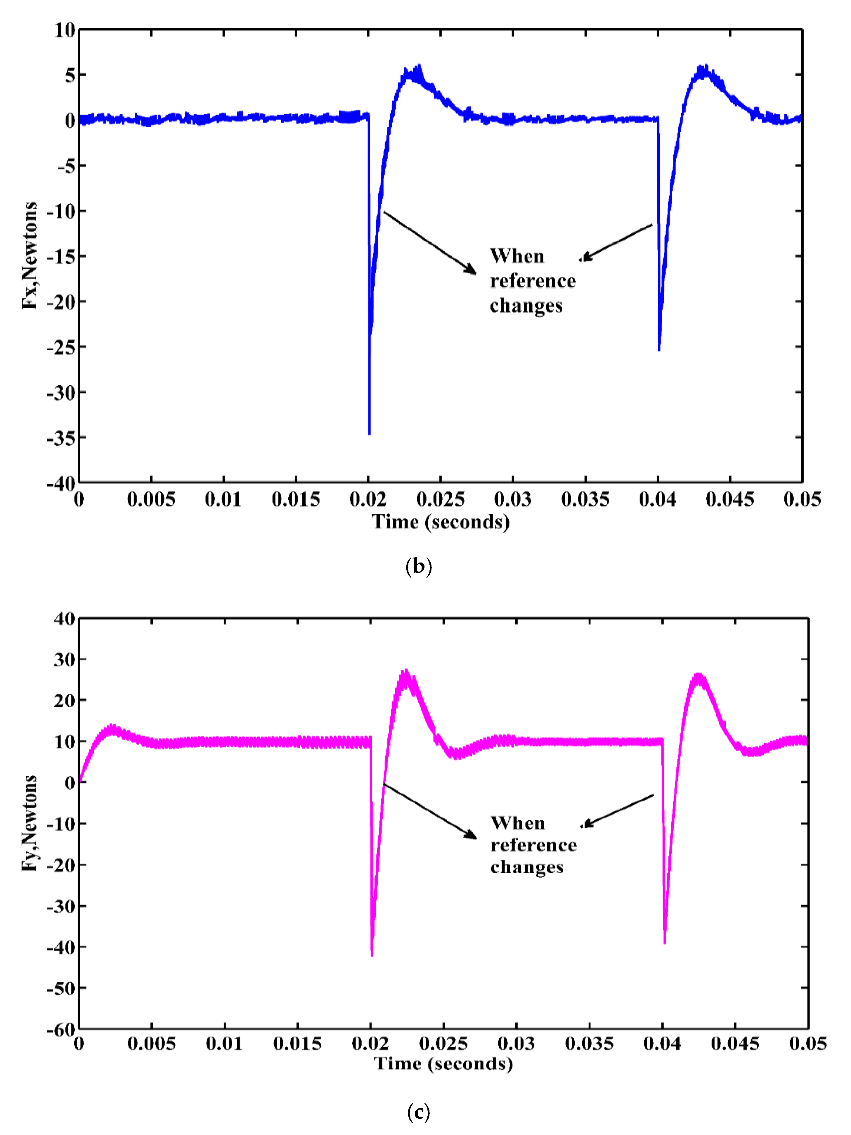
As a first step, the reference values are changed within the first quadrant, i.e., at the time of starting the reference value is kept at (+100 μm, +100 μm) and is changed to (+50 μm, −50 μm) at 0.02 s. Finally, it is varied to the desired location of (0 μm, 0 μm) at 0.04 s in both X and Y directions, respectively. The displacements of rotor and suspension forces in X and Y directions are shown in Figure 18a–c. From Figure 18, it can be observed that the rotor is steadily suspended and steadily rotates at the desired speed, even though there is a large error signal. The proposed controller moves the tracking error of both Xand Y-axis displacements to zero in less time.
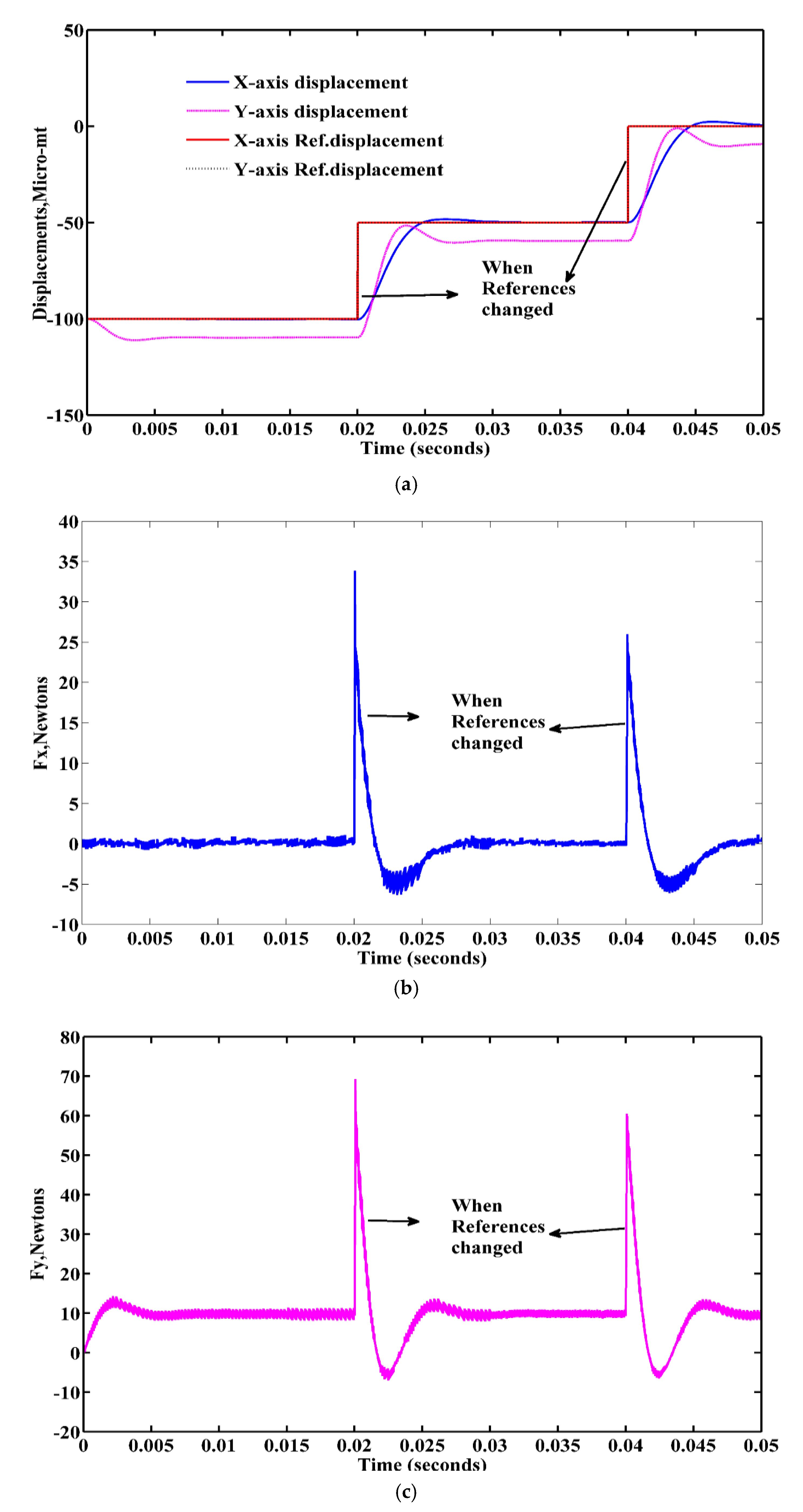
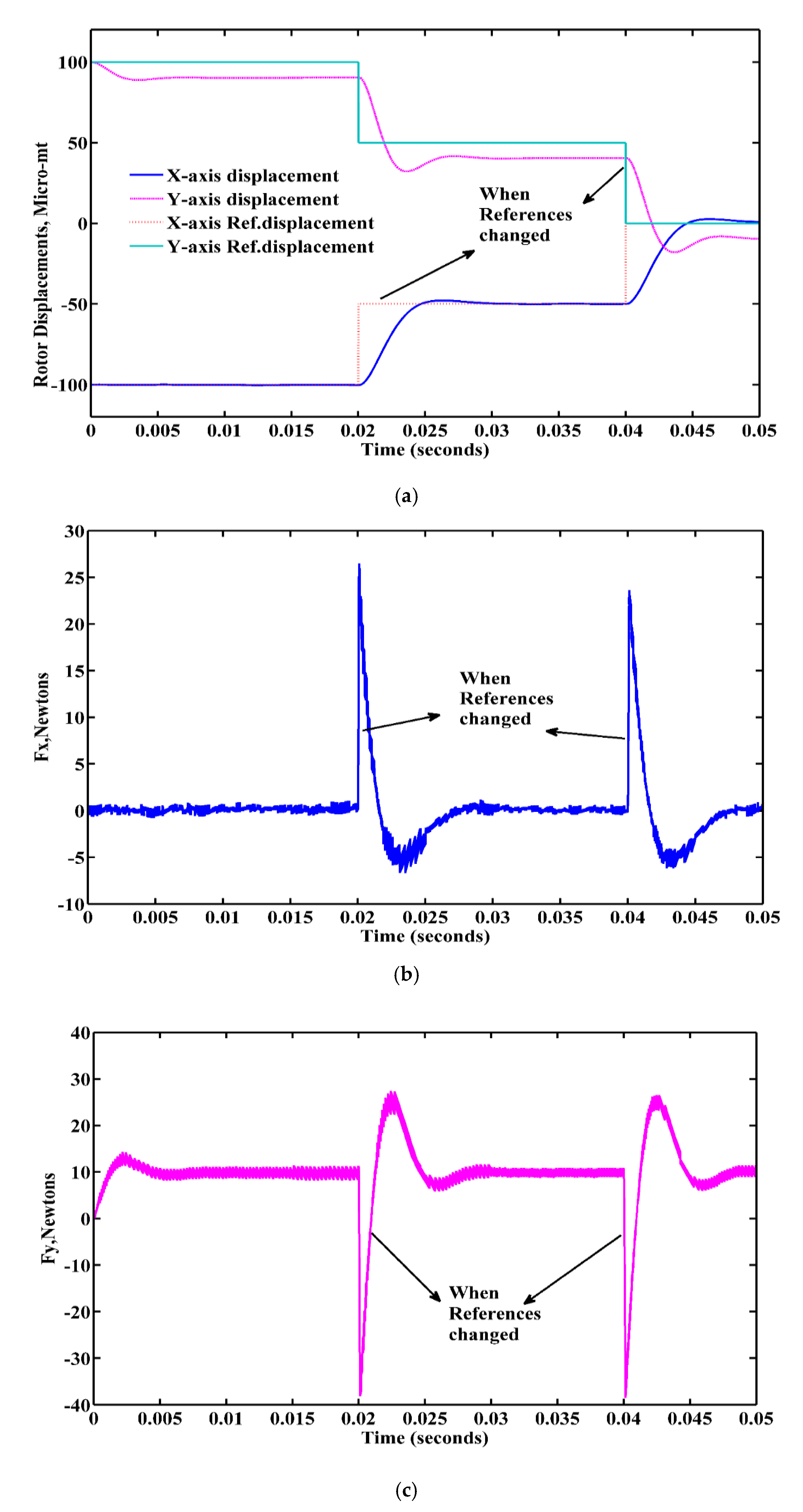
Similarly, the remaining three quadrant reference value changes are shown in Table 4, and the corresponding performance characteristics are shown in Figure 19, Figure 20 and Figure 21.
From the above analysis, the rotor displacements, positions, and suspension forces change slightly at the instant of change of reference and immediately those reach the steady state according to the command signal given in both in X and Y directions. The controller can quickly track the rotor displacements in less than 0.001 s, even though there is a large change in reference from ±100 μm to ±50 μm at 0.02 s, and from ±50 μm to 0 μm at 0.04 s.

4.3.3. Rotor Weight Is Changed

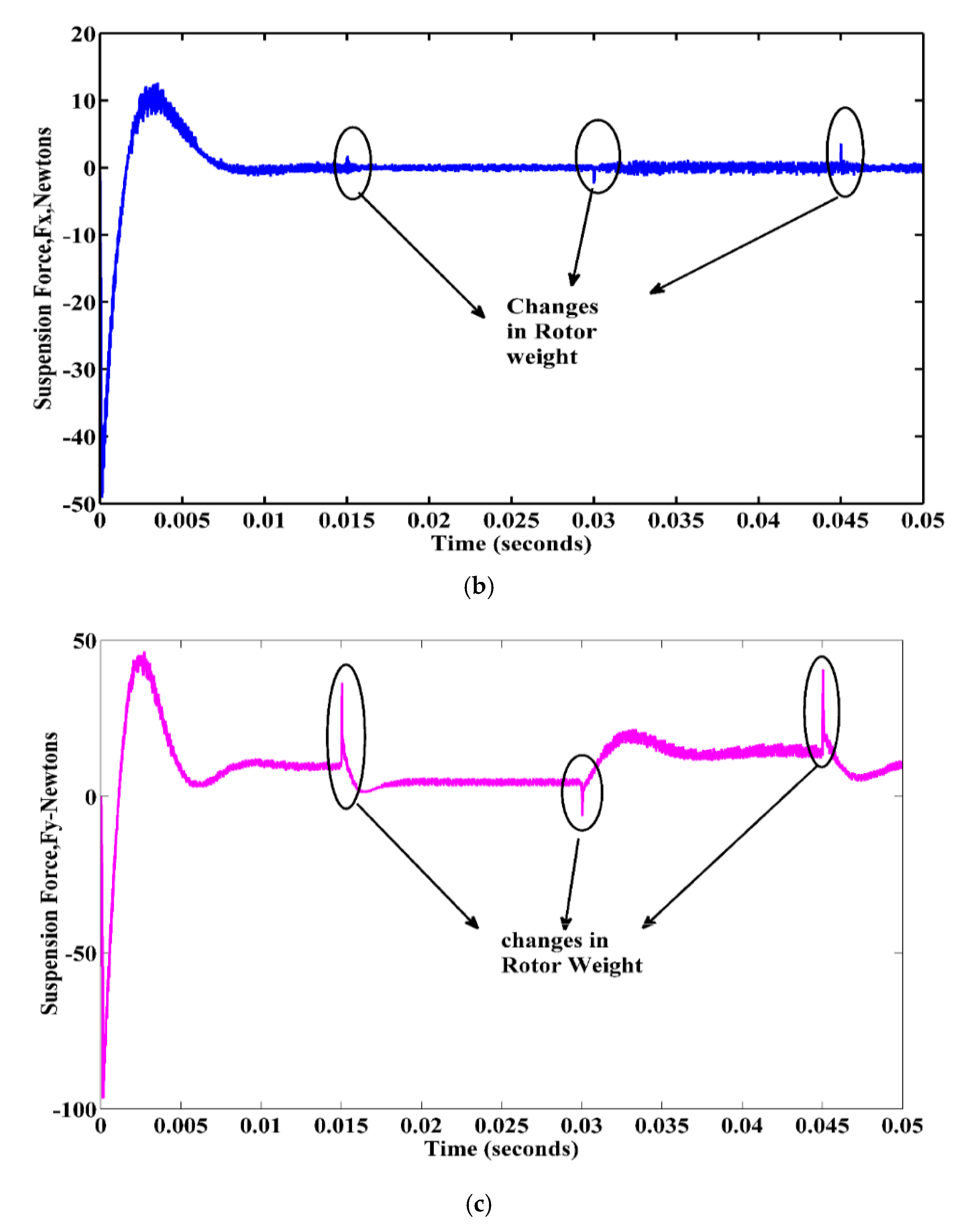
The value of rotor weight plays an important role in the levitation control of the rotor. Practically, there is a possibility of sudden change of rotor weights due to mechanical addition and removal of loads from the load end. The sudden change of rotor weights may lead to the failure of rotation and levitation with the absence of proper control action. In this section, the rotor performance and stability analysis are studied when the rotor is subjected to change of rotor weights with the use of the proposed GSMC controller. In this study, initially, the rotor is kept in the 1st quadrant at a physical eccentric displacement off (+100 μm, +100 μm) from origin in X and Y directions, respectively, and the rotor weight is changed to 1.5 times the original at 0.015 s, at 0.030 s the rotor weight changed to 0.5 times the original, and finally at 0.045 s the rotor is free from extra weights. Figure 22 shows the rotor displacements and suspension forces when the rotor is subjected to a change of weights in both X and Y directions, respectively.
Figure 22a–c show that there is no significant change in the rotor X-directional displacement and its suspension force. This means that the rotor dynamics in the X direction are more robust to the change in rotor weights due to the control action. The rotor displacement and suspension forces in the Y direction are changed due to rotor weights, but the dynamics quickly come to a stable position and maintain a steady levitation due to the proposed control action.

4.3.4. Change in Input Voltages

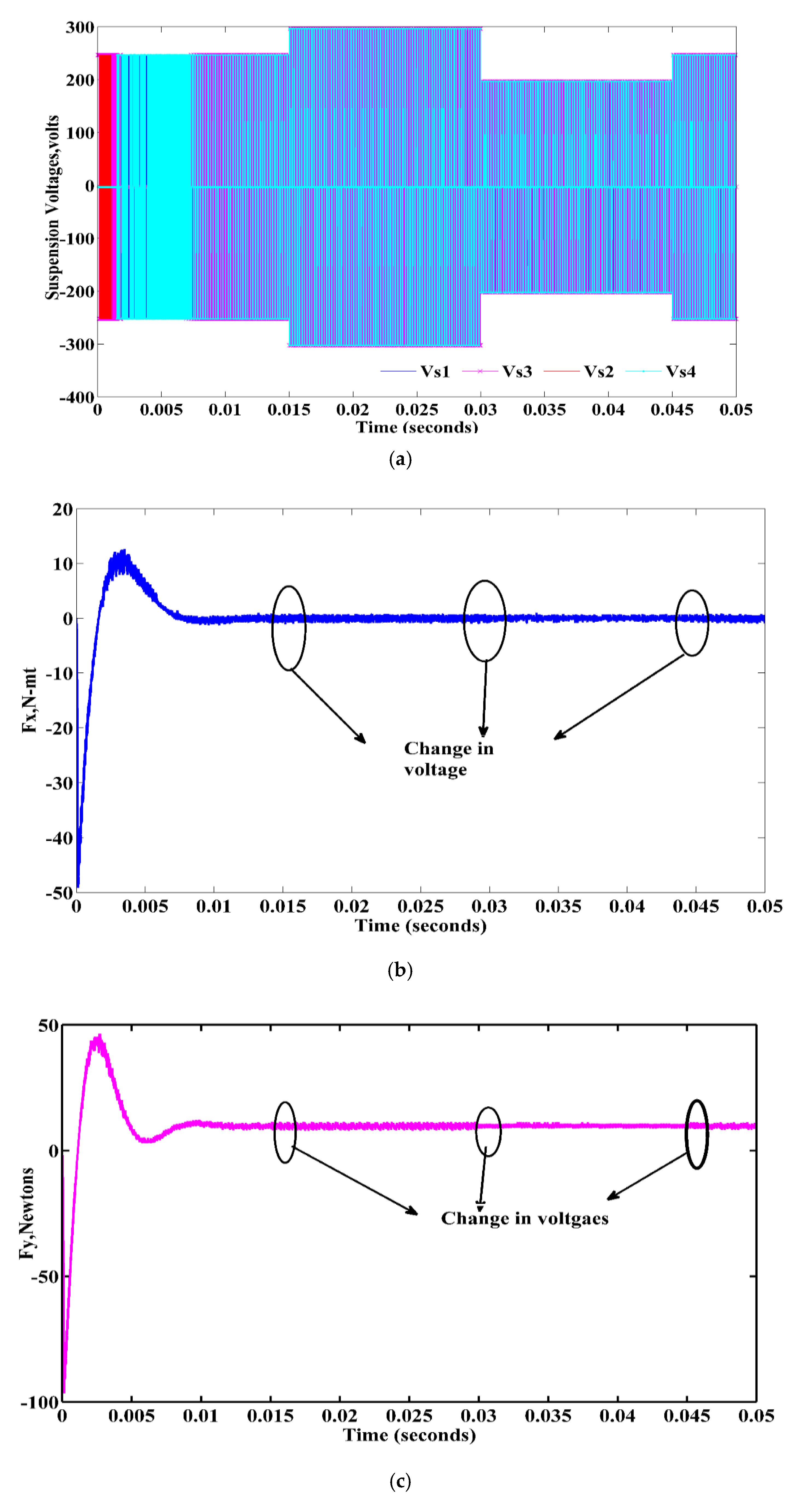
Rotor behavior is observed in this section when the input voltage excitations are changed suddenly. Due to faults of converters and the excitation system, there is a chance of sudden change in voltage. In this study, initially, the rotor is kept in the first-quadrant at an eccentric physical displacement of (+100 μm, +100 μm) from an origin in X and Y directions, respectively, and the phase voltage is varied from 250 v to 300 v at 0.015 s, from 300 v to 200 v at 0.03 s, and from 200 v to 250 v at 0.045 s. Figure 23a–d show the suspension phase’s voltage profile when the suspension system is subjected to a change of voltages, rotor Xand Y-directional displacements and suspension forces, respectively. From the above figures, it can be observed that there is no significant change in rotor X- and Y-directional displacements and its suspension forces because of a disturbance rejection property of control action.

5. Comparisons of Suspension Forces and Displacements with Conventional SMC

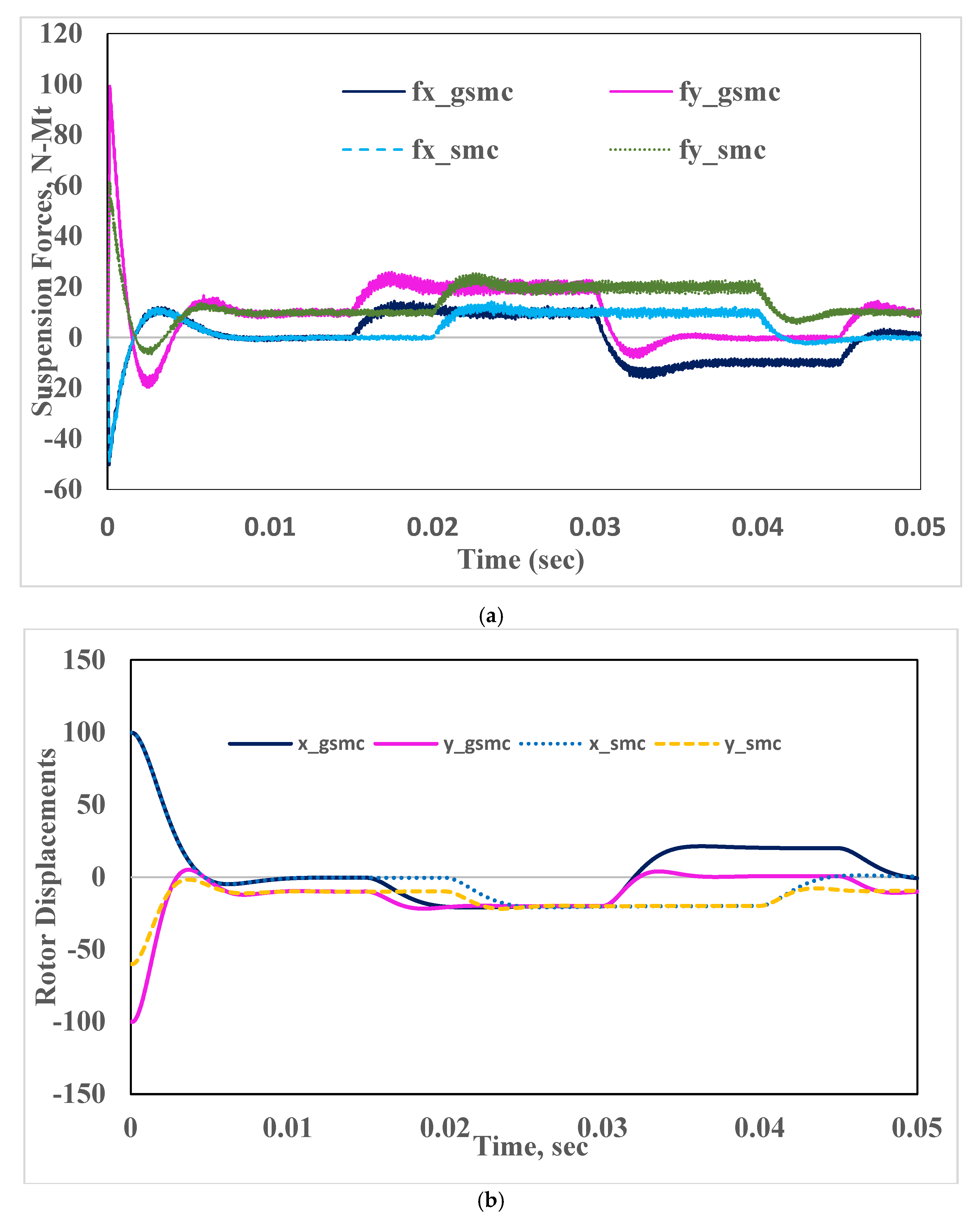
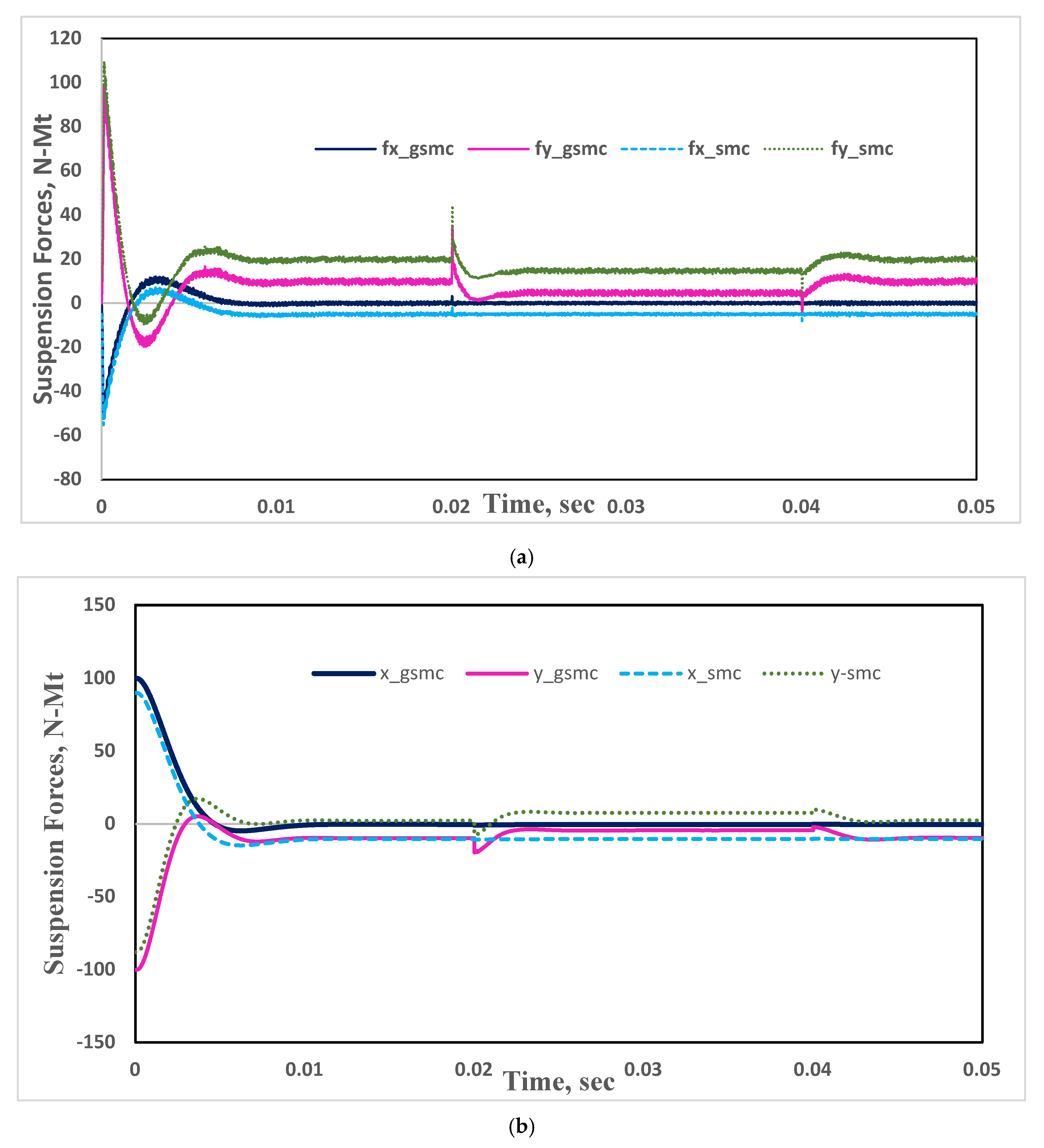
The comparisons of suspension forces and rotor displacements of the proposed GSMC with conventional SMC are shown in Figure 24a,b and Figure 25a,b, under the variations of suspension loads and rotor weights, respectively. From Figure 24 and Figure 25, it can be shown that by using the proposed controller, the rotor reached its steady position quickly, and both the controllers maintain robust behavior against change in the parameters. There is an eccentric displacement in the rotor when the loads are applied, but the rotor can be dragged back to the midpoint position quickly by the proposed controller, and the eccentric direction of the rotor is controlled in both in X and Y directions. Based on the aforementioned analysis, when the suspension parameters are varied, speed and torques are not altered, which means that the suspension force control is decoupled from the torque and speed. Furthermore, regardless of whether the rotor has eccentricity or not, the rotor can be steadily suspended and reach its center position steadily, which verifies the validity of the structure.

6. Conclusions

To align the rotor position at the center and maintain fewer eccentric rotor displacements when BSRM is subjected to different suspension loads, a GSMC is proposed and discussed in this paper. The stabled, robust suspension forces and rotor displacements of the proposed controller are compared with conventional sliding-mode control. The proposed control scheme is employed using MATLAB/Simulink Software.
  • First, the operating principle and mathematical modeling of BSRM is discussed.
  • When the suspension load is applied in the opposite direction, i.e., in the negative, the rotor eccentric direction is also in the opposite, and finally, the rotor dragged back to the center position with the proposed controller.
  • The rotor displacements, positions, and suspension forces are changed slightly at the instant of change of references, and immediately those reached the steady state according to the command signal.
  • When the rotor weight is varied suddenly, there is no significant change in rotor displacement and its suspension force. However, in very little time, the rotor reaches a stable position and maintains steady operation due to the proposed control action.
  • When the suspension system is subjected to a variation of voltages, there is no significant change in rotor X- and Y-directional displacements, and its suspension forces because of the disturbance rejection property of the control action.
With promising performance characteristics obtained from the simulation results, the application of the proposed method can be extended to its implementation in real-time BSRM applications.

Author Contributions

Conceptualization, methodology, software, validation by P.N.R.; formal analysis, investigation, P.N.R., and R.D.; resources, H.M.; data curation, writing—original draft preparation, writing—review and editing, visualization, P.N.R., R.D., and F.P.G.M.; supervision, project administration, funding acquisition, F.P.G.M. All authors have read and agree to the published version of the manuscript.

Funding

The work reported herewith has been financially by the Dirección General de Universidades, Investigación e Innovación of Castilla-La Mancha, under Research Grant ProSeaWind project (Ref.: SBPLY/19/180501/000102).

Conflicts of Interest

The authors declare no conflict of interest.

Nomenclature

Variable NameDescription
m Rotor mass, kg
g Gravity (9.8)
Fx and Fy X- and Y-directional suspension forces respectively
K X and K Y Suspension Force constant matrices
Kxxp, Kyyp Kxyp, Kyxp and Kxxn, Kyyn, Kxyn and KyxnCorresponding Suspension force constants in both positive and negative directions
I x and I Y X- and Y-directional suspension current matrices respectively
ixp,iyp,ixn,iynSuspension currents, amp
ψ ph Flux linkage of torque winding
R ph Resistance of windings, ohms
N Phase inductance reversal matrix
θ Position of the rotor per phase, deg
V Phase voltage vector, volts
w Speed of the rotor, rpm
T e and T l Total electromagnetic torque developed and external applied load torque
B , J , J new   &   Δ J Damping coefficient, actual moment of inertia of rotor and J new = J max + J min 2 , Δ J = J max J min 2
i Phase current vector, amp
X r e f , Y r e f and X d , Y d X- and Y-directional rotor reference and desired displacements, respectively
X 2 , Y 2 Actual rotor displacements in X and Y directions
e x , e y   &   e w Rotor X and Y displacement and speed error equations, respectively
C x , C y   &   C w Rotor X and Y displacement and speed switching function positive constants, respectively
D x , D y   &   D w Rotor X and Y displacement and speed switching exponential term constants, respectively
S x , S y   &   S w Rotor X and Y displacement and speed switching equations, respectively
U x , U y   &   U w Rotor X and Y displacement and speed control equations, respectively

References

  1. Chaibet, A.; Moussa, B.; Ouddah, N.; Monmasson, E. Experimental Sensorless Control of Switched Reluctance Motor for Electrical Powertrain System. Energies 2020, 13, 3081. [Google Scholar] [CrossRef]
  2. Cai, H.; Wang, H.; Li, M.; Shen, S.; Feng, A.Y.; Zheng, J. Torque Ripple Reduction for Switched Reluctance Motor with Optimized PWM Control Strategy. Energies 2018, 11, 3215. [Google Scholar] [CrossRef] [Green Version]
  3. Tchakoua, P.; Benini, E.; Ouhrouche, M.; Slaoui-Hasnaoui, F.; Tameghe, T.A.; Ekemb, G. Wind Turbine Condition Monitoring: State-of-the-Art Review, New Trends, and Future Challenges. Energies 2014, 7, 2595–2630. [Google Scholar] [CrossRef] [Green Version]
  4. Hossain, L.; Hasan, M.; Muyeen, S.M. Methods for Advanced Wind Turbine Condition Monitoring and Early Diagnosis: A Literature Review. Energies 2018, 11, 1309. [Google Scholar] [CrossRef] [Green Version]
  5. Pérez, J.M.P.; Márquez, F.P.G.; Tobias, A.; Papaelias, M. Wind turbine reliability analysis. Renew. Sustain. Energy Rev. 2013, 23, 463–472. [Google Scholar] [CrossRef]
  6. Bichsel, J. The Bearingless Electrical Machine. In Proceedings of the International Symposium on Magnetic Suspension Technology, NASA Langley Research Center, Hampton, VA, USA, 19–23 August 1991; Part 2. pp. 561–573, SEE N92-27788 18-18. [Google Scholar]
  7. Rahaman, M.A.; Fukao, T.; Ohishi, T. Principles and Developments of Bearingless AC Motors; IPEC: Yokohama, Japan, 1995. [Google Scholar]
  8. Takemoto, M.; Shimada, K.; Chiba, A. A Design and Characteristics of Switched Reluctance Type Bearingless Motors. In Proceedings of the 4th International Symposium on Magnetic Suspension Technology, Gifu City, Japan, 30 October–1 November 1997; NASA/CP-1998-207654. pp. 49–63. [Google Scholar]
  9. Takemoto, M.; Chiba, A.; Fukao, T. A new control method of bearingless switched reluctance motors using square-wave currents. In Proceedings of the 2000 IEEE Power Engineering Society Winter Meeting. Conference Proceedings (Cat. No.00CH37077), Singapore, 23–27 January 2000; Institute of Electrical and Electronics Engineers (IEEE): Piscatvey, NJ, USA; Volume 1, pp. 375–380. [Google Scholar]
  10. Takemoto, M.; Chiba, A.; Fukao, T. A Feed-forward Compensator for Vibration Reduction Considering Magnetic Attraction Force in Bearingless Switched Reluctance Motors. In Proceedings of the 7th International Symposium on Magnetic Bearings, Zurich, Switzerland, 23–25 August 2000; pp. 395–400. [Google Scholar]
  11. Takemoto, M.; Suzuki, H.; Chiba, A.; Fukao, T.; Rahman, M. Improved analysis of a bearingless switched reluctance motor. IEEE Trans. Ind. Appl. 2001, 37, 26–34. [Google Scholar] [CrossRef]
  12. Takemoto, M.; Chiba, A.; Fukao, T. A method of determining advanced angle of square-wave currents in bearingless switched reluctance motors. In Conference Record of the 2000 IEEE Industry Applications Conference, Proceedings of the Thirty-Fifth IAS Annual Meeting and World Conference on Industrial Applications of Electrical Energy (Cat. No.00CH37129), Rome, Italy, 8–12 August 2000; IEEE: Piscatvey, NJ, USA, 2001; Volume 37, pp. 1702–1709. [Google Scholar] [CrossRef]
  13. Takemoto, M.; Chiba, A.; Akagi, H.; Fukao, T. Suspending force and Torque of a Bearingless Switched Reluctance Motor Operating in a Region of Magnetic Saturation. In Conference Record of the 2002 IEEE Industry Applications Conference, Proceedings of the 37th IAS Annual Meeting (Cat. No. 02CH37344), Pittsburgh, PA, USA, 13–18 October 2002; IEEE: Piscatvey, NJ, USA, 2002; Volume 1, pp. 35–42. [Google Scholar]
  14. Takemoto, M.; Chiba, A.; Akagi, H.; Fukao, T. Radial Force and Torque of a Bearingless Switched Reluctance Motor Operating in a Region of Magnetic Saturation. IEEE Trans. Ind. Appl. 2004, 40, 103–112. [Google Scholar] [CrossRef]
  15. Morrison, C.R. Bearingless Switched Reluctance Motor. U.S. Patent 6,727,618, 27 April 2004. [Google Scholar]
  16. Chen, L.; Hofman, W. Analytically Computing Winding Currents to Generate Torque and Levitation Force of a New Bearingless Switched Reluctance Motor. In Proceedings of the 12th International Power Electronics and Motion Control Conference, Portoroz, Slovenia, 30 August–1 September 2006; pp. 1058–1063. [Google Scholar]
  17. Chen, L.; Hofmann, W. Performance Characteristics of one Novel Switched Reluctance Bearingless Motor Drive. In Proceedings of the 2007 Power Conversion Conference, Nagoya, Japan, 2–5 April 2007; Institute of Electrical and Electronics Engineers (IEEE): Piscatvey, NJ, USA, 2007; pp. 608–613. [Google Scholar]
  18. Morrison, C.; Siebert, M.; Ho, E. Electromagnetic Forces in a Hybrid Magnetic-Bearing Switched-Reluctance Motor. IEEE Trans. Magn. 2008, 44, 4626–4638. [Google Scholar] [CrossRef]
  19. Chen, L.; Hofmann, W. Analysis of radial forces based on rotor eccentricity of bearingless switched reluctance motors. In Proceedings of the XIX International Conference on Electrical Machines—ICEM, Rome, Italy, 6–8 September 2010; pp. 1–6. [Google Scholar]
  20. Chen, L.; Hofmann, W. Design procedure of bearingless high-speed switched reluctance motors. In Proceedings of the Power Electronics Electrical Drives Automation and Motion (SPEEDAM), Pisa, Italy, 14–16 June 2010; pp. 1442–1447. [Google Scholar] [CrossRef]
  21. Wang, H.J.; Lee, D.H.; Ahn, J.W. Novel Bearingless Switched Reluctance Motor with Hybrid Stator Poles, Concept, Analysis, Design and Experimental Verification. In Proceedings of the The Eleventh International Conference on Electrical Machines and Systems, Wuhan, China, 17–20 October 2008; pp. 3358–3363. [Google Scholar]
  22. Yang, G.; Deng, Z.; Cao, X.; Wang, X. Optimal Winding Arrangements of a Bearingless Switched Reluctance Motor. IEEE Trans. Power Electron. 2008, 23, 3056–3066. [Google Scholar] [CrossRef]
  23. Wang, H.J. Design and Control of a Novel Bearingless Switched Reluctance Motor. Ph.D. Thesis, Industrial System Engineering of the Kyungsung University, Busan, Korea, 2009. [Google Scholar]
  24. Lee, D.-H.; Ahn, J.-W. Design and Analysis of Hybrid Stator Bearingless SRM. J. Electr. Eng. Technol. 2011, 6, 94–103. [Google Scholar] [CrossRef] [Green Version]
  25. Wang, H.; Wang, Y.; Liu, X.; Ahn, J.-W. Design of novel bearingless switched reluctance motor. IET Electr. Power Appl. 2012, 6, 73. [Google Scholar] [CrossRef]
  26. Yang, Y.; Deng, Z.; Yang, G.; Cao, X.; Zhang, Q. A Control Strategy for Bearingless Switched-Reluctance Motors. IEEE Trans. Power Electron. 2010, 25, 2807–2819. [Google Scholar] [CrossRef]
  27. Cao, X.; Deng, Z.; Yang, G.; Wang, X. Independent Control of Average Torque and Radial Force in Bearingless Switched-Reluctance Motors With Hybrid Excitations. IEEE Trans. Power Electron. 2009, 24, 1376–1385. [Google Scholar] [CrossRef]
  28. Ortega, R.; Sarr, A.; Bobtsov, A.A.; Bahri, I.; Diallo, D. Adaptive state observers for sensorless control of switched reluctance motors. Int. J. Robust Nonlinear Control. 2018, 29, 990–1006. [Google Scholar] [CrossRef]
  29. Derdiyok, A.; Inanç, N.; Özbulur, V.; Bilgiç, M.O. Improving performance of switched reluctance motor by fuzzy logic controller. Int. J. Robust Nonlinear Control. 1999, 9, 307–317. [Google Scholar] [CrossRef]
  30. Falahi, M.; Salmasi, F.R. A sliding mode controller for switched-reluctance motor with iterative learning compensation. In Proceedings of the International Conference on Electrical Machines and Systems, ICEMS 2007, Seoul, Korea, 8–11 October 2007; pp. 631–635. [Google Scholar] [CrossRef]
  31. Edwards, C.; Spurgeon, S.K. Robust output tracking using a sliding-mode controller/observer scheme. Int. J. Control. 1996, 64, 967–983. [Google Scholar] [CrossRef]
  32. Chan, C.; Zhan, Y.; Chau, K.T. Stability analysis of fuzzy sliding mode controlled switched reluctance motor drives. In PESC 98 Record, Proceedings of the 29th Annual IEEE Power Electronics Specialists Conference (Cat. No.98CH36196), Fukuoka, Japan, 22 May 1998; IEEE: Piscatvey, NJ, USA, 2002; Volume 2, pp. 1283–1289. [Google Scholar] [CrossRef] [Green Version]
  33. Imine, H.; Madani, T. Sliding-mode control for automated lane guidance of heavy vehicle. Int. J. Robust Nonlinear Control. 2011, 23, 67–76. [Google Scholar] [CrossRef]
  34. Spurgeon, S. Sliding mode observers: A survey. Int. J. Syst. Sci. 2008, 39, 751–764. [Google Scholar] [CrossRef]
  35. Teixeira, L.R.; Oliveira, J.B.; Araujo, A.D. Smooth indirect adaptive sliding mode control. Int. J. Robust Nonlinear Control. 2013, 25, 775–790. [Google Scholar] [CrossRef]
  36. Cheng, Z.; Hou, C.; Wu, X. Global Sliding Mode Control for Brushless DC Motors by Neural Networks. In Proceedings of the 2009 International Conference on Artificial Intelligence and Computational Intelligence, Shanghai, China, 7–8 November 2009; Volume 4, pp. 3–6. [Google Scholar] [CrossRef]
  37. Liu, L.; Han, Z.; Li, W. Global sliding mode control and application in chaotic systems. Nonlinear Dyn. 2008, 56, 193–198. [Google Scholar] [CrossRef]
  38. Boukattaya, M.; Gassara, H.; Tarak, D. A global time-varying sliding-mode control for the tracking problem of uncertain dynamical systems. ISA Trans. 2020, 97, 155–170. [Google Scholar] [CrossRef] [PubMed]
  39. Liu, J.; Wang, X. Advanced Sliding Mode Control for Mechanical Systems; Springer: Berlin/Heidelberg, Germany, 2011. [Google Scholar] [CrossRef]
  40. Rao, P.N.; Rao, G.V.S.K.; Kumar, G.V.N. A Novel Technique for Controlling Speed and Position of Bearingless Switched Reluctance Motor Employing Sensorless Sliding Mode Observer. Arab. J. Sci. Eng. 2017, 43, 4327–4346. [Google Scholar] [CrossRef]
  41. Faiz, J.; Pakdelian, S. Diagnosis of Static Eccentricity in Switched Reluctance Motors Based on Mutually Induced Voltages. IEEE Trans. Magn. 2008, 44, 2029–2034. [Google Scholar] [CrossRef]
  42. Zhu, M.; Zhang, Y.; Xie, Z.; Zhao, B. Method of reducing noise and torque ripple of switched reluctance motor. In Proceedings of the 2017 Chinese Automation Congress (CAC), Jinan, China, 20–22 October 2017; pp. 2761–2765. [Google Scholar] [CrossRef]
  43. Torkaman, H.; Afjei, E. Comprehensive Detection of Eccentricity Fault in Switched Reluctance Machines Using High-Frequency Pulse Injection. IEEE Trans. Power Electron. 2012, 28, 1382–1390. [Google Scholar] [CrossRef]
  44. Torkaman, H.; Afjei, E.; Yadegari, P. Static, Dynamic, and Mixed Eccentricity Faults Diagnosis in Switched Reluctance Motors Using Transient Finite Element Method and Experiments. IEEE Trans. Magn. 2012, 48, 2254–2264. [Google Scholar] [CrossRef]
  45. Zribi, M.; Sira-Ramírez, H.; Ngai, A. Static and dynamic sliding mode control schemes for a permanent magnet stepper motor. Int. J. Control. 2001, 74, 103–117. [Google Scholar] [CrossRef]
Figure 1. The 12/14 BSRM structure and winding pattern.
Energies 13 05485 g001
Figure 2. Suspension winding’s flux distribution.
Energies 13 05485 g002
Figure 3. (a). Torque-winding short flux patterns under Phase A. (b). Torque-winding short flux patterns under Phase B.
Energies 13 05485 g003
Figure 4. Torque-winding inductance profile at different phase currents.
Energies 13 05485 g004
Figure 5. Suspension winding inductance values at different suspension currents.
Energies 13 05485 g005
Figure 6. Nonlinear torque profile of torque winding.
Energies 13 05485 g006
Figure 7. Asymmetric converter switching modes: (a) ideal mode; (b) Mode 1 (Q1: On; Q2: On); (c) Mode 2 (Q1: Off; Q2: On); (d) Mode 3 (Q1: On; Q2: Off); (e) Mode 4 (Q1: Off; Q2: Off). (Note: Q1 and Q2 are IGBT switches, and D1 and D2 are freewheeling diodes).
Energies 13 05485 g007
Figure 8. Switching block diagram for suspension control.
Energies 13 05485 g008
Figure 9. Design and implementation of GSMC (a) Block diagram representation of GSMC; (b) Stepwise flow chart for implementation of global sliding-mode control of BSRM.
Energies 13 05485 g009aEnergies 13 05485 g009b
Figure 10. Complete eccentric control of 12/14 BSRM.
Energies 13 05485 g010
Figure 11. BSRM Suspension parameters. (a) Four-phase controlled suspension winding voltages; (b) Four-phase controlled suspension phase currents; (c) Resultant suspension force Fx; (d) Resultant suspension force (Fy); (e) Rotor X and Y displacements.
Energies 13 05485 g011aEnergies 13 05485 g011b
Figure 12. Motors parameters of BSRM. (a) Resultant speed; (b) Two-phase (Phase-A and B) controlled voltages; (c) Two-phase (Phase-A and B) controlled currents; (d) Rotor positions; (e) Resultant net torque; (f) Speed-tracking error.
Energies 13 05485 g012aEnergies 13 05485 g012b
Figure 13. First Quadrant Suspension parameters. (a) Rotor Xand Y-axis dispalcements when suspension loads are applied; (b) Suspension force in the X-direction when suspension loads are applied; (c) Suspension force in the Y-direction when suspension loads are applied.
Energies 13 05485 g013aEnergies 13 05485 g013b
Figure 14. Second Quadrant suspension parameters. (a) Rotor dispalcements when suspension loads are applied; (b) Suspension force in the X direction when suspension loads are applied; (c) Suspension force in the Ydirection when suspension loads are applied.
Energies 13 05485 g014aEnergies 13 05485 g014b
Figure 15. Third Quadrant suspension parameters. (a) Rotor Xand Y-axis dispalcements when suspension loads are applied; (b) Suspension force in the X direction when suspension loads are applied; (c) Suspension force in the Y direction when suspension loads are applied.
Energies 13 05485 g015aEnergies 13 05485 g015b
Figure 16. Fourth quadrant Suspension parameters. (a) Rotor Xand Y-axis dispalcements when suspension loads are applied; (b) Suspension force in the X direction when suspension loads are applied; (c) suspension force in the X direction when suspension loads are applied.
Energies 13 05485 g016aEnergies 13 05485 g016b
Figure 17. Simple eccentric view of the rotor in air gap.
Energies 13 05485 g017
Figure 18. First Quadrant suspension Parameters. (a) Rotor Xand Y-axis dispalcements when references are changed; (b) Suspension force in the X direction. (c) Suspension force in the Y direction.
Energies 13 05485 g018aEnergies 13 05485 g018b
Figure 19. Second Quadrant supension parameters. (a) Rotor Xand Y-axis dispalcements when references are changed; (b) Suspension force in the X direction; (c) Suspension force in the Y direction.
Energies 13 05485 g019
Figure 20. Third Quadrant suspension parameters. (a) Rotor Xand Y-axis dispalcements when references are changed; (b) Suspension force in the X direction; (c) Suspension force in the Y direction.
Energies 13 05485 g020
Figure 21. Fourth Quadrant suspension parameters. (a) Rotor Xand Y-axis dispalcements when references are changed; (b) Suspension force in the X direction; (c) Suspension force in the Y direction.
Energies 13 05485 g021
Figure 22. Suspension Parameters. (a) Rotor X- and Y-axis dispalcements when rotor weight is changed; (b) Suspension force in the X direction when rotor weight is changed; (c) Suspension force in the Y direction when rotor weight changed.
Energies 13 05485 g022aEnergies 13 05485 g022b
Figure 23. Suspension parameters under the changes in Applied Voltage. (a) Changes in suspension winding voltages; (b) Suspension force in the X direction when suspension voltage is changed; (c) Suspension force in the Y direction when suspension voltage is changed; (d) Rotor Xand Y-directional displacements when suspension voltage is changed.
Energies 13 05485 g023aEnergies 13 05485 g023b
Figure 24. Change in suspension loads. (a) Suspension forces when suspension loads are changed; (b) Rotor Xand Y-directional displacements when suspension loads are changed.
Energies 13 05485 g024
Figure 25. Change in rotor weights. (a). Suspension forces when rotor weights are changed. (b). Rotor X- and Y-directional displacements when rotor weights are changed.
Energies 13 05485 g025
Table 1. BSRM literature.
Ref. No.AuthorsType of BSRM (Design)Remarks
[8,9,10,11]Masatsugu Takemoto et al.8/6 double layer, 3-ph BSRM.Due to both windings on the stator pole, suspension force control and torque control regions are narrow.
[12,13,14]Takemoto et al. 8/6 double layer, 3-ph BSRM with square currents control methods.The regions of generating torque and suspending force cannot be fully used, because the operating point must be selected to compromise between torque and suspending force.
[15,16,17,18,19,20]Chen et al. and Hoffman et al. hybrid rotor structure, called Morrison rotor. The Morrison rotor simplifies the stator design in that it contains only one type of winding.Because of the increase in axial length, the critical speed of the rotor is reduced. Meanwhile, to maintain the rotor at the center, sometimes high reverse torque cannot be avoided.
[21,22,23]Wang, Lee, and Ahn, Proposed a method for bearingless SRM with 8/6 type, in which three windings are loaded with different currents in each commutating period. Consequently, three torques and three lateral forces are generated.To satisfy suspended force, reverse torque is hard to avoid. This method restricts increase of rotor speed. At the same time, for the above two structures, control methods are very complicated to realize steady suspension.
[24,25]Wang, Lee and Ahn,Proposed a new BSRM with hybrid stator poles. In this structure, only half the stator poles are used for the torque. Therefore, power density is very low.In this motor, long flux paths are taken, and flux reversal exists in the stator core, which may increase the magnetic motive force (MMF) requirements and have higher core losses.
[26,27,28] Wang, Lee. and Ahn,A proposed single winding design on 10/8 and 12/14 BSRM obtains a decoupled nature between suspended force and motor torque.There are no windings on the rotor. Two self-regulated DC supplies are given to the suspension and torque coils to achieve the decoupled performance between net levitation force and motor torque of 12/14 BSRM.
Table 2. Operating details of 12/14 BSRM.
SnoRated BSRM DetailsValue
1Total input power to the motor1000 W
2Current/phase (maximum)4 A
3Applied per phase voltage250 V
4Net desired torque 1 N.m
5Rated desired speed 9000 rpm
6Main winding per phase resistance0.86 Ω
7Levitation winding per phase resistance0.32 Ω
8Suspension voltage250 V
9Suspension current (maximum)4 amp
Table 3. Hysteresis current control switching states for BSRM.
Desired ForceSuspending Force Poles SelectionEnable-Is1Enable-Is2Enable-Is3Enable-Is4
If F x 0 , F y o Is1 and Is21100
If F x 0 , F y o Is2 and Is30110
If F x 0 , F y o Is3 and Is40011
If F x 0 , F y o Is4 and Is11001
Table 4. Rotor reference displacements with respect to time in all quadrants.
Rotor Reference Displacements
at 0 s
Reference Displacements
at 0.02 s
Reference Displacements,
at 0.04 s
(100, 100)(50, 50)(0, 0)
(−100, 100)(−50, 50)(0, 0)
(−100, −100)(−50, −50)(0, 0)
(100, −100)(50, −50)(0, 0)
Publisher’s Note: MDPI stays neutral with regard to jurisdictional claims in published maps and institutional affiliations.