Article

Analysis on Double Quench and Instantaneous Power of SFCL Using Two Magnetically Coupled Windings According to Winding Direction

1
Industry-University Cooperation Foundation & Regional-Industrial Application Research Institute, Kongju National University, Chungnam 314-701, Korea
2
Department of Aero Materials Engineering, Jungwon University, Chungbuk 367-805, Korea
3
Department of Electrical Engineering, Soongsil University, 369, Sangdo-ro, Dongjak-gu, Seoul 156-743, Korea
*
Author to whom correspondence should be addressed.
Energies 2020, 13(21), 5533; https://doi.org/10.3390/en13215533
Submission received: 5 August 2020 / Revised: 13 October 2020 / Accepted: 14 October 2020 / Published: 22 October 2020
(This article belongs to the Section F: Electrical Engineering)

Abstract

:
In this study, the characteristics of the double quench and instantaneous power of a superconducting fault current limiter (SFCL) using two magnetically coupled windings were analyzed. In the proposed model of SFCL, two magnetically coupled windings are wound on the iron core and each winding is connected to one superconducting element. When a fault occurs, the SFCL can limit the fault current by the double quench occurrence of two superconducting elements. In order to analyze the influence of the winding direction on the fault current limiting characteristics of the proposed SFCL, two magnetically coupled windings were designed to allow the same and the reverse directions. From the simulated short circuit experiment, the currents and the voltages of two coupled windings and two superconducting elements were measured and the instantaneous power and the double quench occurrence were analyzed. It was confirmed from the experimental results analysis that the fault current limiting characteristics of the SFCL were more favorable in the reverse winding direction than in the same winding direction.

1. Introduction

The continuous increase in power demand and the various distributed power facilities have made the power supply flexible in the power system. However, in the event of a ground fault or short circuit fault, the fault current increases, causing serious damage to the power facility [1,2,3]. As an alternative to solve the problem of the fault current, a superconducting fault current limiter (SFCL) using the unique characteristics of the superconductor was proposed as the most efficient method [4,5,6].
The developed SFCL can be classified into a quenching type and a non-quenching type [7]. The quench type SFCL can be classified into a type using zero impedance characteristics and the other type using Meissner effect, while the non-quench type SFCL can be classified into a saturated magnetic core type SFCL and a diode bridge type SFCL [8,9,10,11]. An SFCL having zero resistance characteristic has a structure in which a fault current detection and a fault current limiting operation are performed simultaneously. However, since the SFCL should handle all fault currents, it is necessary to develop the SFCL with its lower power capacity to limit the fault current [12,13,14,15,16,17,18]. As studies advance to limit the fault current, magnetic flux lock type SFCL and magnetic flux coupling SFCL models using the magnetic flux of two coils have been proposed [15,16,17,18,19,20]. This study’s researchers have published the results of the fault current limiter and the recovery characteristics of a series-connected resistance type SFCL using a magnetically coupled shunt-reactor [21,22].
In this paper, the SFCL using two magnetically coupled windings was proposed and its effective fault current limiting characteristics were investigated through the short-circuit tests. The comparative analysis on the double quench and the instantaneous power of the SFCL, including the joule energy according to the winding direction of its magnetically coupled winding, were performed. From the analysis on the experimental results, the fault current limiting characteristics of the SFCL could be confirmed to be more advantageous in the reverse winding direction compared to the same winding direction from the point of view of the increase in power capacity of the suggested SFCL.

2. Experimental Methods

2.1. Structure and Operational Principle

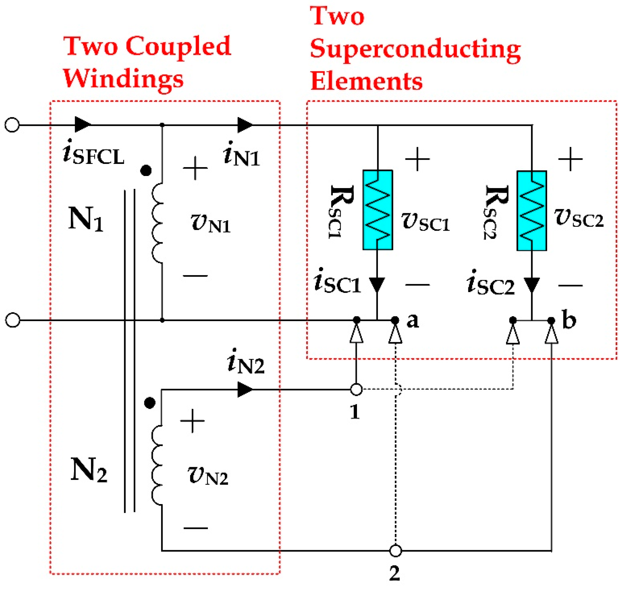
Figure 1 shows the schematic configuration of the proposed SFCL, which two magnetically coupled windings (primary and secondary windings) are wound on the iron core and two superconducting elements are connected with the primary and the secondary windings, respectively. An important parameter of the SFCL is a winding direction of two magnetically coupled windings. The winding direction is named as the reverse winding direction and the same winding direction according to the polarity of the connection direction of the secondary winding (N2) for the primary winding (N1). In case that two magnetically coupled windings have the reverse winding direction, 1 and 2 taps of the secondary winding are connected into a and b points from the primary winding as seen in Figure 1. On the other hand, in case of the same winding direction, 1 and 2 taps of the secondary winding are connected into b and a points from the primary winding as indicated with the dotted line in Figure 1.
The operational principle can be explained with two states (i.e., normal state and fault state). In the normal state, two superconducting elements have zero resistance in the superconducting state and thus, the voltages of the superconducting elements are not generated. The flux induced (Ø1) in the primary winding by the current difference between the SFCL main current (iSFCL) and the primary winding’s current (iN1) is offset by the flux (Ø2) induced by the current of the secondary winding’s current (iN2) as seen in Figure 1.
However, in the fault state, the double quench occurrence in two superconducting elements can make two magnetic fluxes not cancelled, which induces both the voltages in the primary and the secondary windings and can be contributed to limit the fault current. The instantaneous powers of two superconducting elements during the fault cycle are dependent on the winding direction of two magnetically coupled windings, which also induces the joule energy’s difference between two superconducting elements as well as the resistance.
Figure 2 shows the electrical equivalent circuit of the SFCL using two magnetically coupled windings. The reverse winding direction of two coupled windings is constructed with 1 and 2 taps of the secondary winding connected into a and b points from the primary winding (1-a, 2-b). The same winding direction can be modified by exchanging 1 and 2 taps connected into b and a points (1-b, 2-a).
From the electrical equivalent circuit of the SFCL in Figure 2, the voltage of the primary winding (vN1) in the case of the reverse winding direction, which is identical to the voltage of the superconducting element 1 (vSC1), is equal to the difference between the voltage of the superconducting element 2 (vSC2) and the voltage of the secondary winding (vN2) as expressed in Equation (1). In case of the same winding direction from Figure 2, the voltage of the primary winding (vN1) is confirmed to be the sum of the voltage of the superconducting element 2 (vSC2) and the voltage of the secondary winding (vN2) as described in Equation (2):
v N 1 = v S C 1 = + v S C 2 v N 2 ,
v N 1 = v S C 1 = + v S C 2 + v N 2 .

2.2. Experimental Design and Methods

As two superconducting elements, a Yttrium Barium Copper Oxide (YBCO) thin film with the same critical temperature of 87 K and the same critical current of 27 A was used and a 200 nm thick Au layer was deposited on the YBCO thin film to protect it [23,24,25]. The primary and the secondary windings, wound on the iron core, were connected with the superconducting element, respectively.
The experimental circuit for the short circuit experiment is shown in Figure 3. The specifications of the experimental circuit together with the SFCL with two coupled windings are listed in Table 1. As seen in Figure 3, after the switch (SW1) was turned on to supply the power into the load (RL) through the SFCL using two coupled windings, the switch (SW2) was closed at the fault angle of 0° and then turned off after the fault cycles [26]. The currents and the voltages of the SFCL, two superconducting elements, and two coupled windings were measured with the current transformers (CTs) and the potential transformers (PTs).

3. Experimental Results

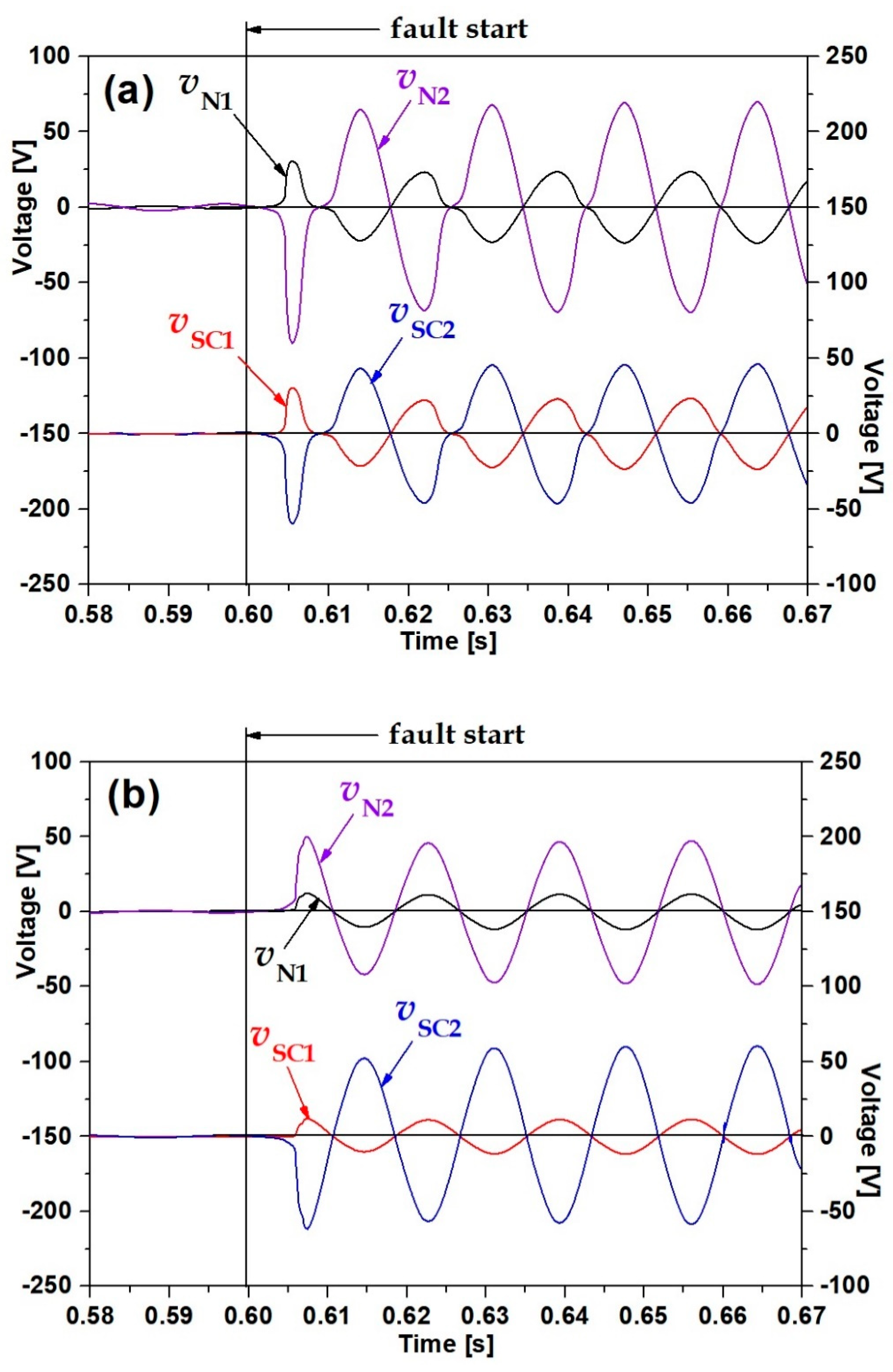
Figure 4 shows the voltage characteristics of the magnetically coupled windings and the superconducting elements according to the winding direction. Figure 4a shows the case that the magnetically coupled winding was in the reverse winding direction. Immediately after the fault occurrence, the voltages of the superconducting elements (vSC1, vSC2) and the magnetically coupled windings (vN1, vN2) were seen to be sharply increased due to the quench of the two superconducting elements. The voltage of the primary winding (vN1), which exhibited the same to the voltage (vSC1) of the superconducting element 1, was observed to be about three times lower than the voltage of the secondary winding (vN2) due to the voltage ratio between the secondary winding and the primary winding. On the other hand, the difference of the phase angle between the voltages of two magnetically coupled windings were 180 degree. As seen in the voltage waveform of the secondary winding (vN2), the phase angle of the superconducting element 2′s voltage (vSC2) was also observed to be reverse or ±180 degree to the phase one of the superconducting element 1′s voltage (vSC1). With the reverse voltage waveform of the superconducting element 2, the voltage of the superconducting element 2 was observed as larger than one of the superconducting element 1 as expressed in Equation (1).
In the case of Figure 4b where two windings were wound on the iron core into the same winding direction, the voltages in two coupled windings as well as two superconducting elements were sharply generated directly after the fault occurrence through the quench of two superconducting elements.
Similar to the reverse winding direction in Figure 4a, the voltage of the superconducting element 2 (vSC2) was observed as larger than one of the superconducting element 1 (vSC1) and the voltages of two superconducting elements had the reversed waveforms each other. However, the voltages of the primary and the secondary windings (vN1, vN2) had the same phase angle and three times amplitude between two windings as seen in Figure 4b.
Figure 5 shows the current and the resistance characteristics of the SFCL and two superconducting elements according to the winding direction. In the reverse winding direction in Figure 5a, the current of the primary winding (iN1), which had the same phase angle to the one of the SFCL (iSFCL) before the fault started, was seen to be reversed directly after the fault started. The current of the superconducting element 2 (iSC2), on the other hand, continued to flow in the opposite direction, irrespective of the fault occurrence. The resistances of two superconducting elements (RSC1, RSC2) were observed to be risen almost simultaneously after the fault occurrence and approached at 1.61 Ω and 2.07 Ω, respectively as indicated in Figure 5a.
In the same winding direction as shown in Figure 5b, the current of the primary winding (iN1), which continued to keep the same phase angle to the one of the SFCL (iSFCL) after the fault happened, increased little more larger than the current of the SFCL. However, the current of the superconducting element 2 (iSC2) had flown in the reverse direction or the opposite one as compared to the reverse winding direction of Figure 5a. The resistance of the superconducting element 2 (RSC2) was increased into the more larger value of 2.57 Ω than one of the superconducting element 1 (RSC1) with 1.22 Ω.
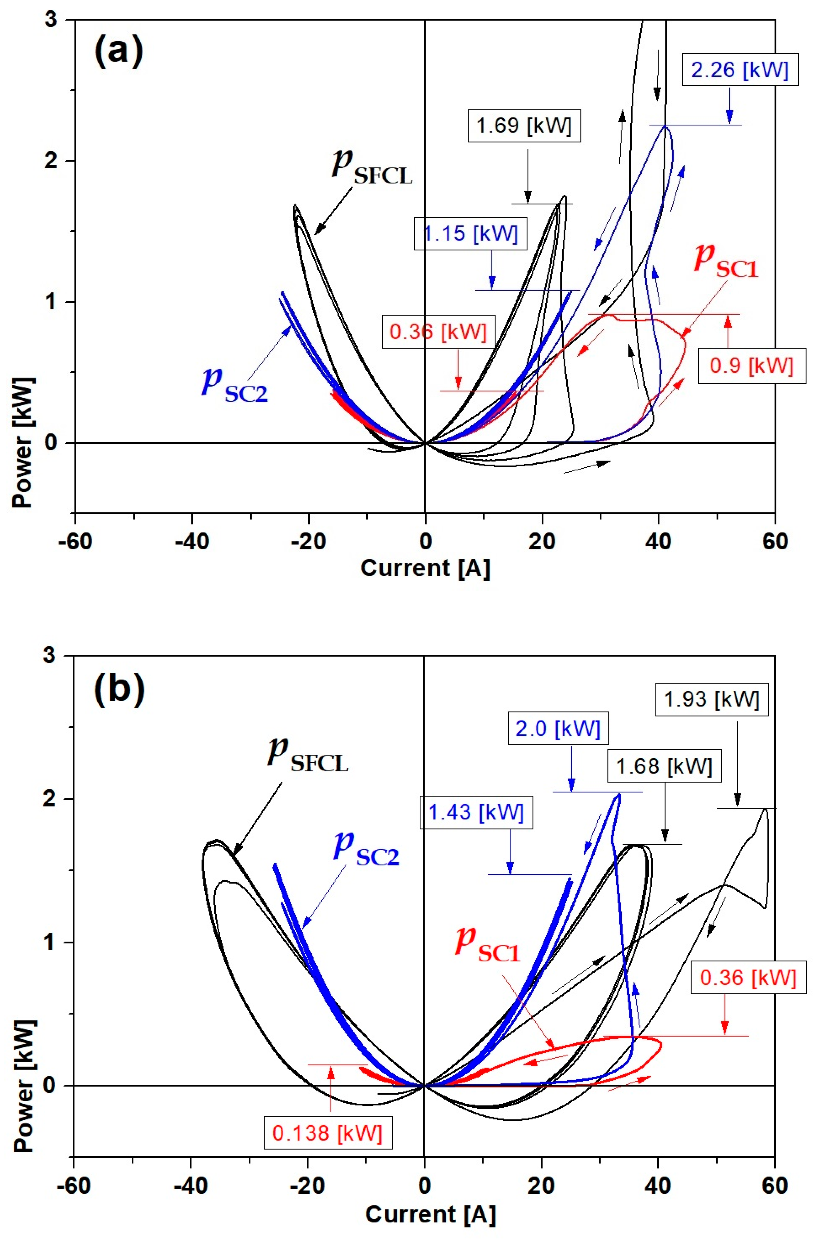
To investigate the instantaneous powers of the SFCL and two superconducting elements due to the winding direction, the instantaneous power curves for currents of the SFCL and two superconducting elements during the fault cycle were displayed in Figure 6.
In the case of Figure 6a, where two coupled windings were connected in the reverse winding direction, the instantaneous power (PSFCL) of the SFCL increased to 3.48 kW immediately after the fault occurrence and converged at 1.69 kW as the fault cycle passed after the quench occurred. The instantaneous powers of two superconducting elements (PSC1, PSC2) converged into about 0.36 and 1.15 kW, respectively, after the instantaneous power increased into the maximum peak value (0.9, 2.26 kW) at the beginning of the fault.
Figure 6b shows the instantaneous power curves for currents of the SFCL and two superconducting elements during the fault cycle in the case of the same winding direction. The power (PSFCL) of the SFCL increased to 1.93 kW immediately after the fault occurrence, and then converged into 1.68 kW. Meanwhile, the instantaneous powers of the two superconducting elements (PSC1, PSC2) converged into 0.138 and 1.43 kW.
From the comparative analysis on the instantaneous power curves in Figure 6, the converged instantaneous power (PSC2) of the superconducting element 2 in the same winding direction was larger than that of the reverse winding direction. However, the instantaneous power of the superconducting element 1 (PSC1) in the same winding direction was lower than that of the reverse winding direction.
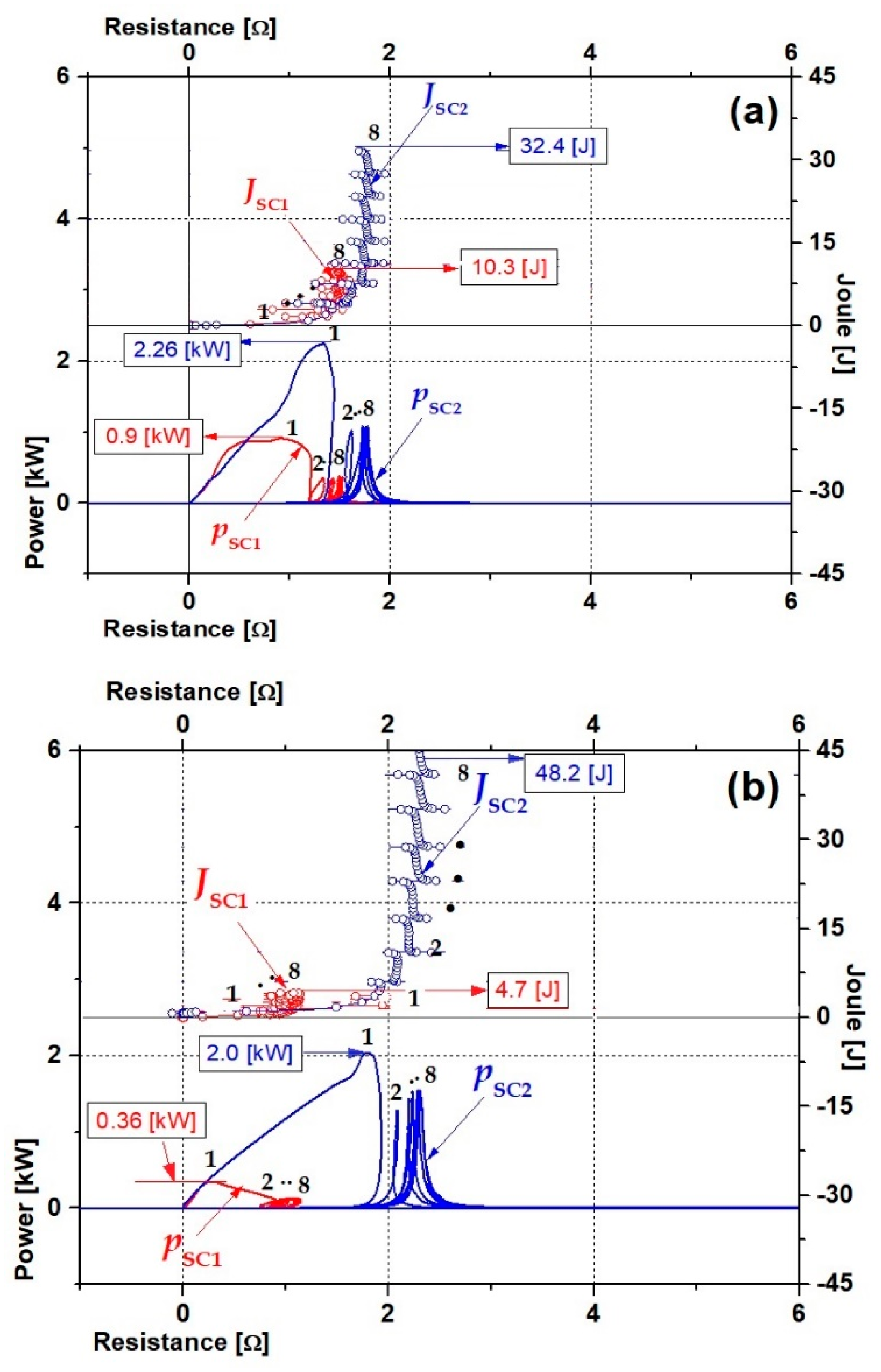
From the instantaneous power curves for currents of two superconducting elements during the fault cycle in Figure 6, the instantaneous power (PSC1, PSC2) and the joule energy (JSC1, JSC2) for the resistance increase of two superconducting elements due to the winding direction were displayed in Figure 7. The joule energy in Figure 7 was calculated by integrating the instantaneous power. In the case that two coupled windings have the reverse winding direction as shown in Figure 7a, the difference of the instantaneous powers between two superconducting elements within one cycle after the quench occurrence was about 1.36 kW or 2.26 kW minus 0.9 kW. The difference of the joule energies between two superconducting elements four cycles after the fault occurrence was 22.1 J, which was calculated from 10.3–32.4 J as indicated with the arrow in Figure 7a.
In Figure 7b of the same winding direction, the instantaneous power and the joule energy in the superconducting element 2 (PSC2, JSC2) can be compared to be larger than ones of the reverse winding direction in Figure 7a. On the other hand, the instantaneous power and the joule energy of the superconducting element 1 (PSC1, JSC1) were analyzed to have the opposite tendency to the case of the reverse winding direction in Figure 7a.
In the case of the same winding direction, the difference between the instantaneous powers and the joule energies of two superconducting elements was 1.64 kW and 43.5 J, respectively. The larger difference between the instantaneous powers and the joule energies for two superconducting elements, especially in the same winding direction, will be required to be decreased because it is disadvantageous to increase the voltage and the current capacity of this type SFCL.

4. Conclusions

In this paper, the SFCL using two magnetically coupled windings was proposed and its fault current limiting characteristics according to the winding direction of two coupled windings were analyzed through the short-circuit experiments. As main variables for the comparative analysis considering the winding direction, the instantaneous power and the joule energy from the measured voltage and current were investigated.
From the analysis on the experimental results, in the case of the revere winding direction, the lower difference between the instantaneous powers and the joule energies of two superconducting elements could be obtained compared to the same winding direction. For the power capacity increase of the suggested SFCL, the design of the reverse winding direction for two coupled windings comprising the SFCL could be confirmed to be more advantageous compared to the same winding direction.

Author Contributions

Writing—original draft preparation, S.-C.K.; Analysis on the experimental data, T.-H.H.; Rewriting—review and editing, S.-H.L. All authors have read and agreed to the published version of the manuscript.

Funding

This research was funded by Basic Science Research Program through the National Research Foundation of Korea (NRF) funded by the Ministry of education (2018R1D1A1B07040471) and the National Research Foundation of Korea (NRF) funded by the Ministry of education (2018R1D1A1B09083558).

Conflicts of Interest

The authors declare no conflict of interest.

Nomenclature

SFCLthe superconducting fault current limiter
N1the primary winding of the two coupled windings
N2the secondary winding of the two coupled windings
SC1the superconducting element 1
SC2the superconducting element 2
ICthe critical current of superconducting element
Einthe AC power supply voltage
Zlnthe line impedance
RLthe load resistance
iN1the current of the primary winding
iN2the current of the secondary winding
iSC1the current of the superconducting element 1
iSC2the current of the superconducting element 2
VN1the voltage of the primary winding
VN2the voltage of the secondary winding
VSC1the voltage of the superconducting element 1
VSC2the voltage of the superconducting element 2
SW1the switch 1 of SFCL
SW2the switch 2 of SFCL
RSC1the resistance of the superconducting element 1
RSC2the resistance of the superconducting element 2
PSFCLthe instantaneous power of the superconducting fault current limiter
PSC1the instantaneous power of the superconducting element 1
PSC2the instantaneous power of the superconducting element 2

References

  1. Hars, T.; Okuma, T.; Yamamoto, T.; Ito, D.; Tasaki, K.; Tsurunaga, K. Development of a new 6.6kV-1500A class superconducting fault current limiter for electric power system. IEEE Trans. Power Deliv. 1993, 8, 181–192. [Google Scholar]
  2. Ye, L.; Lin, L.Z.; Juengst, K.P. Application Studies of superconducting Fault Current Limiters in Electric Power Systems. IEEE Trans. Appl. Supercond. 2002, 12, 900–903. [Google Scholar] [CrossRef]
  3. Antonio, M. State of the art of SFCL and their application to the electric power system. Phys. C Supercond. Appl. 2013, 484, 242–247. [Google Scholar]
  4. Schettino, H.J.; Andrade, R., Jr.; Polasek, A.; Kottonau, D.; Sousa, W.T.B. A strategy for protection of high voltage systems using resistive superconducting fault current limiters. Phys. C Supercond. Appl. 2018, 544, 40–45. [Google Scholar] [CrossRef]
  5. Ye, L.; Campbell, A.M. Case study of HTS resistive superconducting fault current limiter in electrical distribution systems. Electr. Power Syst. Res. 2007, 77, 534–539. [Google Scholar] [CrossRef]
  6. Lorenzo-Fernandez, J.A.; Osorio, M.R.; Veira, J.A.; Tello, M.J.; Vidal, F. Thermal behaviour of high-temperature superconducting fault current limiters; Application to microlimiters. J. Phys. Chem. Solids 2010, 71, 1105–1107. [Google Scholar] [CrossRef]
  7. Jiang, Y.; Dongyuan, S.; Xianzhong, D.; Yuejin, T.; Shijie, C. Comparison of Superconducting Fault Current Limiter in Power System. Power Eng. Soc. Summer Meet. 2001, 3, 43–47. [Google Scholar]
  8. Joo, M.S. Reduction of fault current peak in an inductive high-Tc superconducting fault current limiter. Cryogenics 2005, 45, 343–347. [Google Scholar] [CrossRef]
  9. Xin, Y.; Gong, W.Z.; Niu, X.Y.; Gao, Y.Q.; Guo, Q.Q.; Xiao, L.X.; Cao, Z.J.; Hong, H.; Wu, A.G.; Li, Z.H.; et al. Manufacturing and test of a 35 kV/90 MVA saturated iron-core type superconductive fault current limiter for live-grid operation. IEEE Trans. Appl. Supercond. 2009, 19, 1934–1937. [Google Scholar] [CrossRef]
  10. Lim, S.H.; Kang, H.G.; Han, B.S.; Song, J.J. Analysis of new bridge-type superconducting fault current limiter applying modified magnetic shielding model. Mater. Sci. Eng. B 2003, 102, 348–351. [Google Scholar] [CrossRef]
  11. Hu, Y.; Jianxun, J. Characteristic Analysis of a Fully Controlled Bridge type Superconducting Fault Current Limiter. IEEE Trans. Appl. Supercond. 2016, 26, 5603706. [Google Scholar]
  12. Matsui, H.; Kondo, W.; Tsukada, K.; Sohma, M.; Yamaguchi, I.; Kumagai, T.; Manabe, T.; Arai, K.; Yamasaki, H. Environment-resistive coating for the thin-film-based SFCL Ag/Au–Ag/YBa2Cu3O7/CeO2/Al2O3. Phys. C Supercond. Appl. 2010, 470, 221–224. [Google Scholar] [CrossRef]
  13. Noe, M.; Juengst, K.P.; Werfel, F.N.; Elschner, S.; Bock, J.; Wolf, A.; Breuer, F. Measurements and tests of HTS bulk material in resistive fault current limiters. Phys. C Supercond. Appl. 2002, 372–376, 1626–1630. [Google Scholar] [CrossRef]
  14. Rhee, S.B.; Lee, B.W. Investigation of real field application issues for resistive type SFCLs for distribution electric power networks. Phys. C Supercond. Appl. 2010, 470, 1641–1645. [Google Scholar] [CrossRef]
  15. Matsumura, T.; Shimizu, H.; Yokomizu, Y. Design guideline of flux-lock type HTS fault current limiter for power system application. IEEE Trans. Appl. Supercond. 2001, 11, 1956–1959. [Google Scholar] [CrossRef]
  16. Han, T.H.; Ko, S.C.; Lee, B.G.; Lim, S.H. Study on Current Limiting Characteristics of a Flux-lock type SFCL using Series Connected Two Coils with Twice Triggering Operation. J. Electr. Eng. Technol. 2014, 9, 777–781. [Google Scholar] [CrossRef] [Green Version]
  17. Badakhshan, M.; Mousavi, G.S.M. Flux-lock type of superconducting fault current limiters: A comprehensive review. Phys. C Supercond. Appl. 2018, 547, 51–54. [Google Scholar] [CrossRef]
  18. Han, T.H.; Ko, S.C.; Lim, S.H. Fault Current Limiting Characteristics of a Small-Scale Bridge Type SFCL with Single HTSC Element Using Flux-Coupling. Electonics 2020, 9, 569. [Google Scholar] [CrossRef] [Green Version]
  19. Liu, S.; Xia, D.; Zhang, Z.; Qiu, Q.; Zhang, G. Analysis of a flux-coupling type superconductor fault current limiter with pancake coils. Cryogenics 2017, 87, 18–23. [Google Scholar] [CrossRef]
  20. Lim, S.H. Operational Characteristics of Flux-Lock Type SFCL With Series Connection of Two Coils. IEEE Trans. Appl. Supercond. 2007, 17, 1895–1898. [Google Scholar] [CrossRef]
  21. Lim, S.H.; Kim, J.C. Quench and Recovery Characteristics of Series-Connected Resistive Type SFCLs WITH Magnetically Coupled Shunt-Reactors. IEEE Trans. Appl. Supercond. 2008, 18, 729–732. [Google Scholar]
  22. Han, T.H.; Lim, S.H. Current limiting characteristics of transformer type SFCL with coupled secondary windings according to its winding direction. Prog. Supercon. Cryog. 2017, 19, 44–47. [Google Scholar]
  23. Kim, H.R.; Choi, H.S.; Lim, H.R.; Kim, I.S.; Hyun, O.B. Initial quench development in uniform Au/Y-Ba-Cu-O thin films. IEEE Trans. Appl. Supercond. 2001, 11, 2414–2417. [Google Scholar]
  24. Lim, S.H.; Choi, H.S.; Chung, D.C.; Ko, S.C.; Han, B.S. Impedance variation of a flux-lock type SFCL dependent on winding direction between coil 1 and coil 2. IEEE Trans. Appl. Supercond. 2005, 15, 2039–2042. [Google Scholar] [CrossRef]
  25. Han, T.H.; Lim, S.H. Magnetizing Characteristics of Transformer Type SFCL with additional secondary winding. IEEE Trans. Appl. Supercond. 2018, 28, 5602605. [Google Scholar]
  26. Lim, S.H.; You, L.K.; Kim, J.C. Study on Peak Current Limiting Characteristics of a Flux-Lock Type SFCL Using Its Third Winding. IEEE Trans. Appl. Supercond. 2011, 3, 1275–1279. [Google Scholar] [CrossRef]
Figure 1. Schematic configuration of the SFCL using two magnetically coupled windings.
Energies 13 05533 g001
Figure 2. Electrical equivalent circuit of the SFCL using two magnetically coupled windings.
Energies 13 05533 g002
Figure 3. Experimental circuit for the short-circuit test of the SFCL using two magnetically coupled windings.
Energies 13 05533 g003
Figure 4. Voltage characteristics of two coupled windings and two superconducting elements according to the winding direction: (a) the reverse winding direction (b) the same winding direction.
Energies 13 05533 g004
Figure 5. Current and resistance characteristics of the SFCL and two superconducting elements according to the winding direction: (a) the reverse winding direction (b) the same winding direction.
Energies 13 05533 g005
Figure 6. Instantaneous power curves for currents of the SFCL and two superconducting elements during the fault cycle according to the winding direction: (a) the reverse winding direction (b) the same winding direction.
Energies 13 05533 g006
Figure 7. Instantaneous power and joule energy curves for resistance increase of two superconducting elements during the fault cycle: (a) the reverse winding direction (b) the same winding direction.
Energies 13 05533 g007
Table 1. Specifications of the experimental circuit and the SFCL with two coupled windings.
Experimental CircuitValueUnit
Power source (EIn)AC voltage120Vrms
Frequency60Hz
Line impedance (ZIn)Resistance0.42Ω
Reactance0.066Ω
Load (RL)Resistance5Ω
SFCL using two coupled windingsValueUnit
Two coupled windingsPrimary winding (N1)15Turns
Secondary winding (N2)45Turns
Two superconducting
elements
(SC1, SC2)
MaterialYBCO
Fabrication formThin film
Critical temperature (TC)87K
Critical current (IC)27A
Publisher’s Note: MDPI stays neutral with regard to jurisdictional claims in published maps and institutional affiliations.