Abstract
Aiming to reduce thermal energy loss at the cold side of a thermoelectric generator (TEG) module during thermoelectric conversion, a thermoelectric energy conversion system for heat recovery with a water-cooling energy exchange circuit was devised. The water-cooling energy exchange circuit realized sufficient recovery and reuse of heat accumulated at the cold side of the TEG, reduced the danger of heat accumulation, improved the stability and output capacity of thermoelectric conversion, and provided a low-cost and high-yield energy conversion strategy in energy conversion and utilization. Through the control variable method to adjust the heat generation of the heat source in the thermoelectric conversion, critical parameters (e.g., inner resistance of the TEG, temperatures of thermoelectric modules, temperature differences, output current, voltage, power, and efficiency of thermoelectric conversion) were analyzed and discussed. After using the control variable method to change the ratio of load resistance and internal resistance, the impacts of the ratio of load resistance to inner resistance of the TEG on the entire energy conversion process were elaborated. The results showed that the maximum value of output reached 397.47 mV with a current of 105.56 mA, power of 41.96 mW, and energy conversion efficiency of 1.16%. The power density of the TEG module is 26.225 W/m2. The stability and practicality of the system with a water-cooling energy exchange circuit were demonstrated, providing an effective strategy for the recovery and utilization of heat energy loss in the thermoelectric conversion process.
1. Introduction
Motivated by the broad prospects of thermoelectric conversion technology, such as thermoelectric conversion [1,2,3], the thermoelectric recovery of heat in industry [4,5], and thermoelectric energy supply for microelectronic systems [6], the principles and applications of thermoelectric energy conversion have been widely researched. Unlike the conversion of the kinetic energy of hydropower or wind power into mechanical kinetic energy, which is then converted into electrical energy, thermoelectric conversion technology directly converts thermal energy into electrical energy without requiring another energy transfer process [2,7,8]. Thermoelectric conversion technology, therefore, has obvious advantages over other energy conversion technologies, such as a long service life, no noise, low cost, and environmental protection [2,3,9,10]. On this basis, thermoelectric conversion technology has been widely adopted in energy conversion processes in the aerospace, aviation, and civil industries [11].
As a method of directly converting thermal energy into electrical energy, thermoelectric conversion technology is effective in terms of energy utilization and the recycling of heat. A continuous and stable heat source is central to a thermoelectric conversion system. In recent years, attention has increasingly focused on the heat source of solar energy [1,2,3], the industrial heat source [4,5], and the heat source of the automobile internal combustion engine [12,13,14]. Zhu et al. harvested solar energy to provide energy for a thin-film solar thermoelectric generator (TEG), which acts as a power supply for low-power wireless sensors and microscale devices [1]. Ge et al. discussed the efficiency of a solar TEG when adopting spray cooling, which is better than water cooling when applied as an efficient cooling solution in a solar TEG [2]. Jiang et al. chose a titanium-nitride-based two-dimensional photonic-crystal selective absorber as a solar absorber of a solar TEG, which has good wavelength selectivity and contributes to a larger output voltage [3]. As for industrial heat recovery and utilization, Biswas et al. discussed the process of industrial heat recovery through a simulation that harvested heat from industrial hot air with a Bi2Te3 heat exchanger, indicating the convenience of thermoelectric conversion technology for industrial heat recovery and utilization [4]. Meng et al. recycled exhaust gas heat through thermoelectric power generation and demonstrated a cost-effective thermoelectric power generation system for application in industrial gas heat recovery [5]. Furthermore, Al-Nimr et al. set a thermoelectric module at the surface of a combustion engine, making use of the exhaust energy generated by the internal combustion engine to output electrical energy [12]. Sun et al. and Kunt used high-temperature exhaust gas generated by an internal combustion engine as a heat source, recycling the energy of exhaust gas through a thermoelectric energy conversion module [13,14].
In addition to providing a continuous and stable heat source, the cooling method is central to the thermoelectric conversion system. Recently adopted thermoelectric cooling methods are mainly air-cooling and water-cooling methods, which are widely applied in various thermoelectric power generation devices. Yin et al. illustrated a photovoltaic-thermoelectric system with free air-cooling, forced air-cooling, and water-cooling mechanisms, demonstrating the superiority of water cooling over other cooling methods used for thermoelectric power generation systems [7]. Zhang et al. discussed the performance of a photovoltaic-thermoelectric device having an air-cooling mechanism, the bottom of which is connected with a heatsink to transfer heat energy from inside to outside the environment [8]. Li et al. adopted a water-cooling method and liquid-cooled cold stage to keep the temperature low and stable, which helped thermoelectric energy conversion [11]. Zhang et al. selected an aluminum heatsink radiator as the air-cooling module, which reduced the temperature of the cold side of the thermoelectric power generator [15,16]. Teffah et al. established a TEG with a copper heatsink and a fan for a good air-cooling effect [17]. Lv et al. designed a thermoelectric power generator having a novel heat collector, water-cooled radiator, and thermoelectric modules, providing power for loads in the case of no electricity [18]. Lv et al. devised a solar thermoelectric power generator with a micro-channel heat pipe and tube for cooling water, outputting electrical power and heat energy simultaneously [19]. Zhang et al. chose a water-cooling circuit to keep the cold side of the thermoelectric module stable [20,21]. The above examples clearly show that the cooling method of a thermoelectric conversion system plays an important role in power generation, and further study should be carried out to acquire a stable and high-performance thermoelectric energy supply.
It is clear that the choice of the cooling method is important in enhancing the efficiency of thermoelectric power generation. It can be seen from the above literature that current research mainly focuses on discharging the thermal energy generated by thermoelectric conversion through media such as water flow. Regarding the treatment of heat energy generated by thermoelectric conversion, few studies have focused on how to put the heat energy back into the thermoelectric conversion system for recycling and reuse. The research on the recovery and reuse of the heat generated by thermoelectric conversion has great potential to further improve energy efficiency. Aiming to reduce the thermal energy loss at the cold side of the TEG module during thermoelectric conversion, this research focuses on the recovery and reuse of the heat accumulated at the cold side of the TEG. Given the above situation, a thermoelectric power generation system for the sufficient recovery and reuse of heat accumulated at the cold side of the TEG with a water-cooling energy exchange circuit is proposed. To enhance the heat recovery effect of the system, two water-cooled heads with cooling water circulation grooves inside are closely set on the cold-side surfaces of the thermoelectric cooler (TEC) and TEG modules. Through the structure, the heat accumulated at the cold side of the TEG is absorbed by the cooling water flowing inside the water-cooled head located at the cold end of the TEG. Then, the heat absorbed by the cooling water is transferred from the cold end of the TEG module to the cold end of the TEC module through the water-cooling energy exchange circuit. Finally, the heat that reaches the cold end of the TEC module is transported back to the hot side of the TEC module for recovery and reuse, providing thermal energy for a new round of thermoelectric energy conversion. As the Seebeck effect states, the larger the temperature difference, the greater the thermoelectric voltage [22]. Hence, the output voltage of the thermoelectric energy conversion system is improved because of the higher temperature generated by the increased heat transported back to the hot side of the TEC module for thermoelectric energy conversion. The thermoelectric power generation system with a water-cooling energy exchange circuit is suitable for small-scale equipment with TEC modules and circulating water circuits, such as small water dispensers and small refrigerators. By storing and outputting the electrical energy generated by the system due to heat recovery and reuse, the power consumption of the above equipment will be further reduced. For tropical regions and subtropical southern regions with high temperatures all year round, the aforementioned function of the system for heat recovery and reuse will be more obvious.
The organizational structure of this paper is as follows. After introducing the issue of the recovery and reuse of heat accumulated at the cold side of the TEG, the experimental materials and methods of the thermoelectric energy conversion system are demonstrated. Then, the changing tendencies of output parameters, such as the output voltage, current, and output power of the thermoelectric energy conversion system, are analyzed and discussed. The power density of the TEG module with and without a water-cooling energy exchange circuit is obtained and compared. Subsequently, the economic analysis of the system is carried out, showing that the thermoelectric energy conversion system for heat recovery is suitable, economical, and practical for the supply of power to low-power loads. Finally, the study concludes that the system provides an effective solution for the heat treatment of semiconductor thermoelectric technology. Through the above research, an effective recovery and reuse solution to the heat accumulation of semiconductor thermoelectric technology is described, which provides a reference for further heat recovery and reuse research in the semiconductor thermoelectric field.
2. Materials and Methods
Figure 1 and Figure 2 show the core structure of the thermoelectric energy conversion system for heat recovery with a water-cooling energy exchange circuit. The circuit includes an active water-cooling part and a passive water-cooling part. The active water-cooling part includes a water-cooled head (40 × 40 × 12 mm3) set on the cold surface of the TEC module, transparent water-cooled pipes (with internal diameters of 8 mm, shown in Figure 1 and Figure 2), a water pump shown in Figure 1 but blocked by the screen in Figure 2 (4 V direct current (DC), 0.6 W, maximum size of pump head (Hmax) = 110 cm, maximum pump capacity (Qmax) = 150 L/h), and a water-cooling tank (410 × 230 × 260 mm3, shown in Figure 1 and Figure 2). The passive water-cooling part includes a water-cooled head (40 × 40 × 12 mm3) set on the cold surface of the TEG module, transparent water-cooled pipes, and a water-cooling tank (shown in Figure 1 and Figure 2).
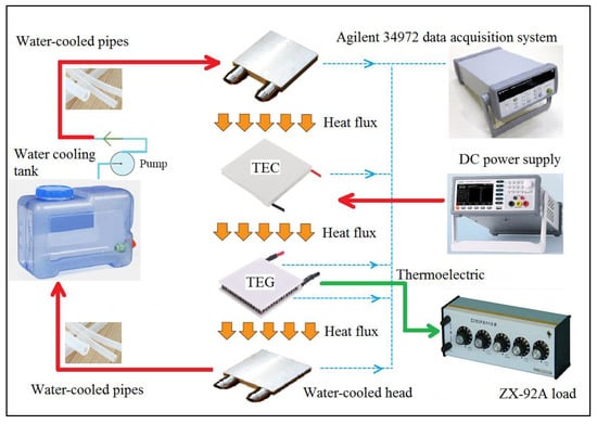
Figure 1.
Schematic diagram of thermoelectric energy conversion system for heat recovery with circulating energy exchange water-cooling circuit.

Figure 2.
Experimental rig of thermoelectric energy conversion system for heat recovery with circulating energy exchange water-cooling circuit.
The water-cooled heads of the active and passive water-cooling parts communicate through transparent water-cooled plastic pipes, which forms a water-cooling circuit and contributes to the transfer of heat from the cold surface of the TEG module to that of the TEC module. When the TEC module is powered directly by electricity, the cold side of the module absorbs heat, and the hot side releases heat. The released heat reaches the hot side of the TEG module, resulting in a temperature difference between the hot and cold sides of the TEG module. With the accumulation of heat, the thermal energy of the cold side of the TEG module gradually increases. Then, the passive water-cooling part of the system begins to absorb heat on the cold side of the TEG. As the passive water-cooling part and the active water-cooling part of the system are connected by transparent water-cooled pipes, the absorbed heat is transferred through the transparent water-cooled pipes to the active water-cooling part of the system, which releases heat on the cold side of the TEC module. Finally, the absorbed heat is recovered back to the TEC module and released as heat energy to the hot side of the TEG for a new thermoelectric conversion.
The TEC and TEG modules were the TEC-12705 (40 × 40 × 3.95 mm3) and TEG-1.27-1.36-1.52 (40 × 40 × 3.85 mm3) modules manufactured by TECooler. The detailed parameters of TEC-12705 and TEG-1.27-1.36-1.52 are shown in Table 1. As shown in Figure 2, a programmable DC power supply (A-BF SS-L3010SPL) provides input voltages and currents for the TEC module. The temperatures of the hot and cold surfaces of the TEC and TEG modules were acquired by thermocouples of the K type (Thermometers TT-K-30-SLE, Omega, USA), allowing the recording of the tendency of the change in temperature of cooling water flowing in the water-cooled heads of the water-cooling circuit. To measure the output characteristics of the TEG module, an output characteristic test circuit, comprising a Keysight 34972 Lxi Data Acquisition/Switch Unit, Agilent 34901 Data Acquisition Card, variable load (ZX-92A of the Shanghai Zhengyang Instrument Factory), was employed. Figure 3 shows a detailed picture depicting the position of the thermocouples and TEC and TEG modules.

Table 1.
Parameters of TEC-12705 and TEG-1.27-1.36-1.52 modules of TECooler.
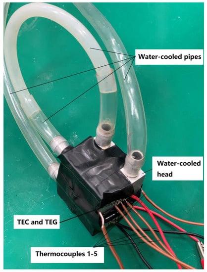
Figure 3.
Detailed picture depicting position of thermocouples and thermoelectric cooler (TEC) and thermoelectric generator (TEG) modules.
A mathematical model was created to study the output performance of the water-cooled thermoelectric energy-harvesting device. Assumptions were made to simplify the energy conversion process: that the heat transfer of the energy conversion process is steady; in the flow direction, the thermal properties of the cooling water flowing in the water-cooling circuit depend on the temperature; and the temperatures of the components of the water-cooled thermoelectric energy-harvesting device are independent.
According to the Peltier effect, the energy of the hot and cold sides of the TEC can be calculated as follows [20]:
where , , , , , , and are, respectively, the Seebeck coefficient of the TEC module, the energy absorbed by the hot side of the TEC module, the energy released by the cold side of the TEC module, the electrical current of the TEC module, the hot-side temperature of the TEC module, the cold-side temperature of the TEC module, the thermal conductance of the TEC module, the internal electric resistance of the TEC module, and the temperature difference between the hot and cold sides of the TEC modu
The DC power supply can be obtained by multiplying the input voltage and the input current :
As for the TEG, according to the Peltier effect, the energy of the hot and cold sides of the TEG and the output power of the TEG module can be calculated as follows [16]:
where , , , , , , , , and are, respectively, the Seebeck coefficient of the TEG module, the energy acquired by the hot side of the TEG module, the energy released by the cold side of the TEG module, the electrical current of the TEG module, the hot-side temperature of the TEG module, the cold-side temperature of the TEG module, the thermal conductance of the TEG module, the internal electric resistance of the TEG module, and the temperature difference between the hot and cold sides of the TEG module.
The total resistance is the sum of and :
It follows that,
According to [15], the energy conversion efficiency of the TEG module is:
Supposing that is m times as large as , then the output power of the TEG module can be acquired as follows:
The figure of merit of the TEG, , is obtained as follows [17]:
where N is the value of the thermocouples of the TEG and is the thermal conductivity of the TEG.
Applying Equations (10)–(12), the energy conversion efficiency of the TEG module can be calculated as follows:
3. Experimental Results and Discussion
Experiments were carried out for two scenarios. One scenario was the thermoelectric energy conversion system for heat recovery with an increasing input current and a constant load. The other was the thermoelectric energy conversion system for heat recovery with a constant input power and variable loads.
3.1. Thermoelectric Cooler (TEC) Performance Characteristics
As shown in Figure 4, the DC power supply directly supplies the TEC module with current increasing from 0.25 to 3.25 A at an output voltage increasing from 0.71 to 12.23 V. The continuously increasing current and voltage gradually increase the cooling capacity of the TEC module, resulting in a gradually increasing temperature difference between the hot and cold sides of the TEC module. In the early, middle, and late stages of the experiment, with input voltages and currents of 0.71 V and 0.25 A, 5.49 V and 1.75 A, and 12.23 V and 3.25 A, the hot- and cold-side temperatures of the TEC module, respectively, reach 300.09 and 297.52 K, 321.78 and 298.67 K, and 366.45 and 310.17 K. The hot-side and cold-side temperatures of the TEC module are presented in Figure 5.

Figure 4.
Dependence of VIN, Rload on input current.
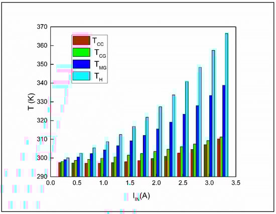
Figure 5.
Dependence of TH, TCG, TMG and TCC on input current.
The tendency of the change in the inner resistance of the TEC module is shown in Figure 4. It is clear that with the greater hot- and cold-side temperature difference of the TEC module shown in Figure 5, the inner resistance of the TEC module increases steadily. As the input current rises to 1.25 A, the inner resistance increases from 2.83 to 2.99 Ω. The reason for this phenomenon is that the internal heat accumulation of the TEC module in the refrigeration process has a dynamic relation with the heat exchange with the outside during cooling, and the final heat storage gradually increases. When the input current exceeds 1.25 A, the internal heat accumulation of the TEC module gradually stabilizes, which contributes to the stable increase in internal resistance with input current. The internal resistance of the TEC peaks at 3.77 Ω when the input voltage and current are, respectively, 12.23 V and 3.25 A. The 33.22% increase in the inner resistance of the TEC module from 2.83 to 3.77 Ω indicates that the internal resistance of the TEC module positively correlates with the accumulation of heat inside the TEC structure.
The hot-side surface of the TEG module is tightly engaged with the hot-side surface of the TEC module to improve the efficiency of energy transfer between the TEG and TEC modules, which helps maximize the use of heat generated by the TEC module during its cooling process. As the temperature of the hot-side surface of the TEC module shown in Figure 5 rises, the temperature of the hot-side surface of the TEG module, which closely adheres to the hot-side surface of the TEC module, rises steadily, resulting in a continuous rise of the temperature of the hot-side surface of the TEG module from 300.09 to 366.45 K.
During this period, the cold-side surface temperatures of the TEC and TEG modules shown in Figure 5 rise slowly in a small range (i.e., from 297.52 to 310.17 K and from 298.19 to 311.23 K, respectively). The reason for this is that two water-cooled heads are closely attached to the cold-side surfaces of the TEC and TEG modules, forming a circulating energy exchange water-cooling circuit through the transparent water-cooled plastic pipes, water-cooling pump, and water-cooling tank. When the cooling-water pump is working, cooling liquid enters the water-cooled head connected to the cold side of the TEG module from the water tank and absorbs heat through the transparent water-cooled plastic pipes. The cooling liquid is then transferred to the other water-cooled head connected to the cold side of the TEC module through the transparent water-cooled plastic pipes, which is absorbed at the cold-side surface of the TEC module.
Based on the heat transfer between the hot-side surface of the TEC module and that of the TEG module, the temperature difference between the hot-side and cold-side surfaces of the TEG module can be calculated from the results presented in Figure 5. The temperature difference gradually increases from 1.90 to 55.22 K, resulting in a continuous rise in the output voltage of the TEG module. According to the Seebeck effect, the output voltage of the TEG module is proportional to the temperature difference between the hot-side and cold-side surfaces of the TEG module. Figure 6 shows that the maximum output voltage of the TEG module is 397.47 mV, with the temperature difference between the hot-side and cold-side surfaces of the TEG module being 55.22 K.

Figure 6.
Dependence of VOUT, IOUT on input current.
As calculated from the results presented in Figure 5, the temperature change on the cold-side surface of the TEC module is less than the temperature change on the cold-side surface of the TEG module when the input current increases from 0.25 to 3.25 A. However, when the input current exceeds 3.25 A, the output voltage of the energy conversion of the TEG module drops greatly, which means that the energy conversion of the TEG module is no longer normal. In conclusion, the optimal working ranges of the circulating energy exchange water-cooling circuit including two water-cooled heads closely attached to the cold-side surfaces of the TEC and TEG modules, the transparent water-cooled plastic pipes, the water-cooling pump, and the water-cooling tank are an input current from 0.25 to 3.25 A and an input voltage from 0.71 to 12.23 V.
3.2. Thermoelectric Generator (TEG) Performance Characteristics
Figure 6 and Figure 7 show the experimentally obtained output voltage, output current, output power, energy conversion efficiency, and related parameters. As the input current rises, the output voltage, output current, output power, and energy conversion efficiency improve simultaneously. The maximum values of the aforementioned parameters are 397.47 mV, 105.56 mA, 41.96 mW, and 1.16%, respectively, when the input current is 3.25 A and the load resistance is equal to the inner resistance of the TEC and TEG modules. The power density of the thermoelectric energy conversion system is 26.225 W/m2. The output power and power density clearly show the application prospects of the thermoelectric energy conversion system for heat recovery with a circulating energy exchange water-cooling circuit that is able to recycle and reuse heat of 26.225 W/m2 using a single TEG module.

Figure 7.
Dependence of POUT, φ on input current.
3.3. Output Characteristics of System under Various Load Resistances
A variable-load box is applied to test the output parameters of the thermoelectric energy conversion system for heat recovery. The output parameter test experiments are performed at a moderate input current and voltage, namely 2.00 A and 6.45 V. In this case, the resistance of the variable-load box in the test circuit is gradually increased from 1 to 180 Ω. Figure 8, Figure 9 and Figure 10B show the trends of critical output parameters as the load increases.

Figure 8.
Dependence of VOUT, E, IOUT, and IEX on load resistance.

Figure 9.
Dependence of TCG, TCC, THD,CG and THD,CC on load resistance.

Figure 10.
(A) Dependence of RIN/RALL, RIN–EX/RALL, Rload/RALL and Rload–ex/RALL on load resistance. (B) Dependence of POUT, POUT–EX, φ, and φEX on load resistance.
The output voltage and current of the thermoelectric energy conversion system for heat recovery are shown in Figure 8. When the input current and voltage are, respectively, selected as 2.00 A and 6.45 V, the output voltage varies from 24.63 to 774.86 mV, while the resistance of the variable-load box is controlled in the range of 1–180 Ω. In the same period, the output current drops from 48.56 to 4.30 mA. As the resistance of the variable-load box increases, an upward trend of the output voltage and downward trend of the output current gradually become clear, indicating that the maximum output power can be obtained during this process. The maximum output voltage and current of the system shown are obtained when the input current and voltage are, respectively, selected as 2.00 A and 6.45 V. A maximum output voltage of 774.86 mV and output current of 48.56 mA are shown in Figure 8 by V–R and I–R curves. However, the maximum output voltage and current are not obtained at the same time. The trend curves of the output voltage and current in Figure 8 show that an appropriate combination of current and voltage is needed to realize the maximum output power.
Figure 9 presents the temperature changes on the cold sides of the TEG and TEC modules when the water-cooled heads are attached to the cold sides of the TEG and TEC modules. Benefitting from the circulating energy exchange water-cooling circuit, the temperature change of the aforementioned parameters on the load resistance is stable, indicating that the experimental process is a sufficient thermoelectric conversion and heat energy exchange process. The changing tendencies of and are shown in Figure 10A. With the increasing value of load resistance, the value of drops from 0.798 to 0.011, while that of increases from 0.202 to 0.989.
The maximum output power of the system shown in Figure 10B is 12.11 mW. The top plot of the output power is obtained when the resistance of the variable-load box is selected as 20 Ω. It is found that the resistance of the variable-load box is not equal to the internal resistance of the TEG module when the highest output power is obtained. This is mainly due to the fact that when the TEG module and water-cooling head connected to the cold side of the TEG module exchange heat efficiently, too small a load (e.g., less than 20 Ω) makes it difficult to fully drive the thermoelectric conversion of the TEG module. This results in a large thermal energy loss through the water-cooled head and circulating energy exchange water-cooling circuit. The energy conversion efficiency of the thermoelectric process shown in Figure 10B varies from 0.04% to 0.49%. The variation is due to changes in the temperatures on the hot and cold sides of the TEG module and the slight change in the inner resistance of the TEG module. The maximum energy conversion efficiency of the thermoelectric process is acquired when the load resistance is 3.50 Ω, which is slightly larger than the inner resistance of the TEG module. The results agree with those in the literature, showing the correctness and accuracy of the acquisition of experimental output parameters. The maximum output power of the system for a selected input current and voltage of 2.00 A and 6.45 V (i.e., 12.11 mW) is shown in Figure 10B. The maximum energy conversion efficiency is obtained when the appropriate combination of current and voltage is 24.60 mA and 492.19 mV. The electric power supply shown in Figure 10B can fully support the distributed power needs of low-power wireless sensors when a system works solely or in series, which is of particular importance in developing the energy recycling of heat generated by TEC modules.
3.4. Comparison of Output Characteristics with Different Value of Rload–ex/RIN
As shown in Figure 8 and Figure 10A,B, the output characteristics with a different value of are acquired as , , , and . All of the aforementioned parameters are obtained when the inner resistance of the TEG is 2 Ω. Under this circumstance, the changing tendencies of the aforementioned output characteristics are acquired when the inner resistance of the TEG is smaller than that shown in Table 1. Obviously, as shown in Figure 8, with a smaller inner resistance of the TEG, the value of is larger than that of . The largest value difference between and is 23.21 mA. The value difference between and shows the value of the voltage of inner resistance of the TEG. As the load resistance increases, the value difference between and decreases from 155.31 to 13.80 mV.
As for the output power and efficiency shown in Figure 10A, the largest value difference between and is 3.051 mW. The value of is larger than that of during the increase of load resistance, indicating that a smaller and stable inner resistance value contributes to the improvement of the TEG’s output power. The value difference between and gradually changes from positive to negative as the load resistance increases. The maximum and minimum of the value difference between and are 0.084 and −0.086. The negative efficiency difference means that the value of the energy conversion efficiency of the system when the inner resistance of the TEG is set as 2 Ω is smaller than the value of the energy conversion efficiency of the system when the inner resistance of the TEG is slightly larger than 2 Ω during the continuous energy conversion process. The occurrence of the above phenomenon is closely related to the ratio of load resistance to internal resistance. As the load resistance continues to increase, the difference between the smaller internal resistance and the load resistance gradually becomes larger, eventually leading to a further decrease in thermoelectric conversion efficiency. The above results show that the smaller internal resistance can improve the thermoelectric conversion efficiency of the system to a certain extent while increasing the output power. However, under the effect of a smaller internal resistance, as the load resistance continues to increase, the thermoelectric conversion efficiency of the system eventually decreases to maintain a higher output power. As shown in Figure 10B, the largest thermoelectric conversion efficiency of the system is around 0.5%. The value is obtained when the input current and voltage are 2.00 A and 6.45 V, respectively. It is worth noting that the two values 1.16% and about 0.5% were obtained under different experimental environment settings. The value of 1.16% is obtained when the input voltage and current are 12.25 V and 3.25 A while the load resistance is equal to the inner resistance of the thermoelectric conversion module. The value of around 0.5% is obtained when input voltage and current are 6.45 V and 2.00 A while the load resistance is larger than the inner resistance of the thermoelectric conversion module.
3.5. Comparison of Circulating Energy Exchange Water-Cooling Circuit with Air Cooling
The maximum output voltage of the thermoelectric energy conversion system for heat recovery with a load resistance equal to the TEG inner resistance load resistance is 397.47 mV when the input current of the DC power supply is set from 0.2 to 3.25 A. Related experiments were conducted in previous work [17], where the highest open-circuit voltage of the TEC–TEG system incorporating forced air cooling and cooling fins was 600 mV when the input voltage of the DC power supply was set in the range of 1–5 V. As the highest open-circuit voltage in [17] was tested when the load resistance was zero, the data obtained in the previous work are equivalent to those for an output voltage of 300 mV when the load resistance equals the TEG internal resistance. Therefore, the results obtained in the present paper are 97.47 mV higher than those in previous work with air cooling, which verifies the accuracy of the experimental parameters and the high practicality of the experimental device.
In terms of practical value, the thermoelectric energy conversion system for heat recovery with a water-cooling energy exchange circuit is able to power low-power wireless sensors that receive, process, and dispatch data when working solely or in series. Furthermore, the system with the circulating energy exchange water-cooling circuit has its own advantages over other cooling methods such as water cooling. Under conditions of higher temperature, such as summer conditions, the water-cooling method will have a better cooling effect than other cooling methods such as air cooling because of the lower temperature of cooling water relative to other heat transfer media like cooling air. Moreover, the circulating energy exchange water-cooling circuit has the advantages of no noise and high stability.
The output parameters in the present paper indicate that the cooling level of the thermoelectric energy conversion system for heat recovery with a water-cooling energy exchange circuit has room for improvement. In-depth studies on the material of water-cooled heads, the contact area of the water-cooling medium, and the displacement of the water-cooling pump will assist the design of a better power supply source for low-power wireless sensor networks, especially those set in water-rich environments. As a heat transfer medium, the water circulating in the water tank and the water-cooling circuit gradually absorb and release heat energy during the entire heat transfer process. During long-term experiments, the temperature of the water tank rises slightly. The magnitude and speed of the temperature rise of the water tank are closely related to the temperature of the cold side of the thermoelectric module, water flow rate, specific structure of the water tank, and heat exchange efficiency between the water, water tank, and external environment. The generated power decreases slightly with the change of the cooling condition of the cold side of the thermoelectric module. During long-term experiments, the water temperature of the water-cooling circuit rises slightly, leading to a decrease in the cooling performance of the cold side of the thermoelectric module. As a result, the value of the generated power decreases slightly due to the decrease in the cooling performance of the cold side of the thermoelectric module under the above circumstances.
With a stable input current and voltage, the operating power consumption of the TEC-12705 module is fixed. However, to achieve efficient energy conversion and transmission, effective heat dissipation is required on the hot side of the TEC-12705 module. The heat to be dissipated includes the heat released by the panel effect and the Joule heat of the TEC-12705 module, which can be removed largely by a strong active cooling system, such as a Noctua NH-D15 air cooler (12 V, 0.96–1.56 W). The disadvantage of a strong active cooling system is that much external electricity is consumed. Thus, the consumption of electrical energy has greatly restricted the efficient energy conversion, transmission, and wide application of the TEC modules. This leads to the use of the TEC modules, such as the TEC-12705 module, being limited to small water dispensers or small refrigerators. In order to solve the above problem, with a circulating energy exchange water-cooling circuit comprising water-cooled heads attached on the cold sides of the TEG-1.27-1.36-1.52 and TEC-12705 modules, transparent water-cooled plastic pipes transporting cooling water through the whole circuit, a water-cooling pump (4 V DC, 0.6 W, maximum pump head size (Hmax) = 110 cm, the maximum pump capacity (Qmax) = 150 L/h), and water-cooling tank, the thermoelectric energy conversion system for heat recovery reduces the operating power consumption of strong active cooling from 0.36 to 0.96 W and generates considerable energy up to 41.96 mW, showing an acceptable cost performance when applied in TEC working areas, such as small water dispensers and small refrigerators. As the area of the TEG module is 40 × 40 mm2, the power density of the TEG module is 26.225 W/m2. For comparison, the output parameters of a device without the water-cooling energy exchange circuit are tested and obtained. The results showed that the output of a device without the water-cooling energy exchange circuit reached 327.61 mV with a current of 88.12 mA, power of 28.87 mW. The power density of the TEG module is 18.043 W/m2. The above data shows that the water-cooling energy exchange circuit has a positive effect on increasing the power density of the thermoelectric conversion module. After calculation, the power output growth rate of a thermoelectric conversion module with the water-cooling energy exchange circuit relative to a thermoelectric conversion module without the water-cooling energy exchange circuit is 45.34%. Correspondingly, benefiting from the heat recovery and reuse function of the water-cooling energy exchange circuit, the power density output by the thermoelectric conversion module is increased by 1.45 times. The above results well demonstrate the positive effect of the thermal power recovery and reuse structure on improving the output performance of the thermoelectric conversion module. Therefore, the application of thermal power recovery and reuse structure to the thermoelectric recovery system has great research potential and practical value.
The material cost of the thermoelectric energy conversion system for heat recovery comprises costs for the TEG and TEC modules (30 USD), two water-cooled heads (6 USD), transparent water-cooled plastic pipes (4 USD), water-cooling pump (7 USD), water-cooling tank (9 USD), output electrical circuit material (5 USD), insulation materials (3 USD), and fixed clamping assembly (3 USD). The total material cost is 67 USD.
When the thermoelectric energy conversion system is installed with related electrical equipment containing TEC components, the equipment can provide power for the TEC work and water-cooling pump work with its inner electrical circuits. The output of the device can, therefore, be calculated to evaluate the annual production of the thermoelectric energy conversion system. Supposing the output electricity of the device is 41.96 mW and the TEG device works 8 h a day and 360 days a year, the device can output 435.04 kJ in one year. The benefits are clear and profitable, which provides evidence for the practical value of the TEG applications. When the thermoelectric conversion efficiency of the system is stable, it is feasible to apply the system to low-power appliances containing TEC modules and circulating water pipelines, such as water dispensers and small refrigerators. In order to increase the energy savings and output power of the system, connecting the system in series and adding energy storage and output management circuits is an effective application strategy. In the above operability, the power consumption of low-power appliances such as water dispensers and small refrigerators will be reduced through the system’s thermoelectric conversion output. For tropical and subtropical southern regions such as Kunming and other perennial high-temperature regions, compared to subtropical northern regions such as Beijing, the heat recovery and reuse efficiency of the above system will be further improved.
4. Conclusions
A thermoelectric energy conversion system for heat recovery with a water-cooling energy exchange circuit was devised. The main contributions are as follows:
- (1)
- The heat accumulation in the thermoelectric energy conversion process is harmful for the normal working of thermoelectric modules. With a water-cooling energy exchange circuit, the increase of the inner resistance of the TEG caused by heat accumulation becomes less than 1 Ω when the current and voltage increase by 3.5 A and 12 V, respectively.
- (2)
- The ratio of load resistance to inner resistance is a core parameter to increase thermoelectric output performance. When the inner resistance is constant at 2 Ω, the largest increase between POUT–EX and POUT is acquired as 3.051 mW, while the largest value difference between IEX and IOUT is 23.21 mA.
- (3)
- The ratio of load resistance to inner resistance has a crucial impact on the energy conversion efficiency. The 2 Ω constant value of inner resistance makes the value difference between φEX and φ gradually change from positive to negative. The maximum and minimum of the value difference between φEX and φ are 0.084 and −0.086.
- (4)
- With a water-cooling energy exchange circuit, the maximum value of output reaches 397.47 mV with a current of 105.56 mA, power of 41.96 mW, and energy conversion efficiency of 1.16% when the load resistance is constant. The power density of the TEG module is 26.225 W/m2.
In conclusion, with a water-cooling energy exchange circuit, the thermoelectric energy conversion system for heat recovery further reduces the danger of heat accumulation, improves the stability and output capacity of thermoelectric conversion, and provides a low-cost and high-yield energy conversion strategy in energy conversion and utilization.
Author Contributions
All authors contributed to the paper. W.L., provided guidance, supervision, and revised the paper; Z.Z., designed the research, conceived the idea of the study, and wrote the paper; Z.Z., Y.Z. and X.S., performed the experiment and discussed experimental results; Z.Z. and D.X., discussed the experimental results and revised the paper. All authors read and approved the final manuscript.
Funding
The authors gratefully acknowledge the financial support from the National Science Foundation of China (31670716), the China Postdoctoral Science Special Foundation (2016T90044) and the China Postdoctoral Science Foundation (2015M570945).
Conflicts of Interest
The authors declare no conflict of interest.
Nomenclature
| Energy absorbed by hot side of TEC. | |
| Energy released by cold side of TEC. | |
| Energy acquired by hot side of TEG. | |
| Energy released by cold side of TEG. | |
| Direct electric power supply of TEC. | |
| Output power of TEG. | |
| Output power of TEG when is set as 2 Ω. | |
| Output current of TEG. | |
| Output voltage of TEG. | |
| Energy conversion efficiency of TEG. | |
| Energy conversion efficiency of TEG when is set as 2 Ω. | |
| The figure of merit of TEG. | |
| Thermal conductance of TEG. | |
| Thermal conductance of TEC. | |
| Seebeck coefficient of TEG. | |
| Seebeck coefficient of TEC. | |
| Output current of TEG. | |
| The current across the TEC. | |
| Output current of TEG when is 2 Ω. | |
| Input voltage of DC supply. | |
| Input current of DC supply. | |
| Seebeck electromotive force produced by TEG. | |
| Hot-side temperature of TEC. | |
| Cold-side temperature of of TEC. | |
| Temperature difference of hot and cold sides of TEC. | |
| Hot-side temperature of close-fitting TEC and TEG. | |
| Average temperature of hot and cold sides of TEG. | |
| Hot-side temperature of TEG. | |
| Cold-side temperature of of TEG. | |
| Temperature difference of hot and cold sides of TEG. | |
| Temperature of water-cooled heads attached to the cold sides of the TEG. | |
| Temperature of water-cooled heads attached to the cold sides of the TEC. | |
| Internal electric resistance of TEC. | |
| Internal electric resistance of TEG. | |
| Constant Internal electric resistance of TEG set as 2 Ω. | |
| Total resistance of thermoelectric output circuit. | |
| Load resistance of thermoelectric output circuit. | |
| Load resistance of thermoelectric output circuit when is set as 2 Ω. | |
| m | The ratio of to . |
| The value of thermocouples of TEG. |
References
- Zhu, W.; Deng, Y.; Gao, M.; Wang, Y.; Cui, J.L.; Gao, H.L. Thin-film solar thermoelectric generator with enhanced power output: Integrated optimization design to obtain directional heat flow. Energy 2015, 89, 106–117. [Google Scholar] [CrossRef]
- Ge, M.H.; Wang, Z.X.; Liu, L.S.; Zhao, J.; Zhao, Y.L. Performance analysis of a solar thermoelectric generation (STEG) system Check for with spray cooling. Energy Convers. Manag. 2018, 177, 661–670. [Google Scholar] [CrossRef]
- Jiang, D.Y.; Fan, Z.; Dong, M.; Shang, Y.; Liu, X.H.; Chen, G.J.; Li, S. Titanium nitride selective absorber enhanced solar thermoelectric generator (SA-STEG). Appl. Therm. Eng. 2018, 141, 828–834. [Google Scholar] [CrossRef]
- Biswas, S.; Roynaskar, A.; Hirwani, C.K.; Panda, S.K. Design and fabrication of thermoelectric waste heat reutilization system possible industrial application. Int. J. Energy Res. 2018, 42, 3977–3986. [Google Scholar] [CrossRef]
- Meng, F.K.; Chen, L.G.; Feng, Y.L.; Xiong, B. Thermoelectric generator for industrial gas phase waste heat recovery. Energy 2017, 135, 83–90. [Google Scholar] [CrossRef]
- Dhawan, R.; Madusanka, P.; Hu, G.Y.; Debord, J.; Tran, T.; Maggio, K.; Edwards, H.; Lee, M. Si0.97Ge0.03 microelectronic thermoelectric generators with high power and voltage densities. Nat. Commun. 2020, 11, 4362. [Google Scholar] [CrossRef]
- Yin, E.; Li, Q.; Xuan, Y.M. Thermal resistance analysis and optimization of photovoltaic-thermoelectric hybrid system. Energy Convers. Manag. 2017, 143, 188–202. [Google Scholar] [CrossRef]
- Zhang, J.; Xuan, Y.M.; Yang, L.L. Performance estimation of photovoltaic-thermoelectric hybrid systems. Energy 2014, 78, 895–903. [Google Scholar] [CrossRef]
- Zoui, M.A.; Bentouba, S.; Stocholm, J.G.; Bourouis, M. A Review on Thermoelectric Generators: Progress and Applications. Energies 2020, 13, 3606. [Google Scholar] [CrossRef]
- He, W.; Wang, S.X.; Yue, L.K. High net power output analysis with changes in exhaust temperature in a thermoelectric generator system. Appl. Energy 2017, 196, 259–267. [Google Scholar] [CrossRef]
- Li, L.; Gao, X.; Zhang, G.; Xie, W.Y.; Wang, F.F.; Yao, W. Combined solar concentration and carbon nanotube absorber for high performance solar thermoelectric generators. Energy Convers. Manag. 2019, 183, 109–115. [Google Scholar] [CrossRef]
- Al-Nimr, M.A.; Alajlouni, A.A. Internal combustion engine waste heat recovery by a thermoelectric generator inserted at combustion chamber walls. Int. J. Energy Res. 2018, 42, 4853–4865. [Google Scholar] [CrossRef]
- Sun, X.X.; Liang, X.Y.; Shu, G.Q.; Tian, H.; Wei, H.Q.; Wang, X.X. Comparison of the two-stage and traditional single-stage thermoelectric generator in recovering the waste heat of the high temperature exhaust gas of internal combustion engine. Energy 2014, 77, 489–498. [Google Scholar] [CrossRef]
- Kunt, M.A. An experimental investigation of exhaust waste heat recycling by thermoelectric generators under different thermal conditions for internal combustion engines. Proc. Inst. Mech. Eng. Part D J. Automob. Eng. 2018, 232, 1648–1653. [Google Scholar] [CrossRef]
- Zhang, Z.; Li, W.B.; Kan, J.M. Behavior of a thermoelectric power generation device based on solar irradiation and the earth’s surface-air temperature difference. Energy Convers. Manag. 2015, 97, 178–187. [Google Scholar] [CrossRef]
- Zhang, Z.; Li, W.B.; Kan, J.M.; Xu, D.C. Theoretical and experimental analysis of a solar thermoelectric power generation device based on gravity-assisted heat pipes and solar irradiation. Energy Convers. Manag. 2016, 127, 301–311. [Google Scholar] [CrossRef]
- Teffah, K.; Zhang, Y.T.; Mou, X.L. Modeling and Experimentation of New Thermoelectric Cooler-Thermoelectric Generator Module. Energies 2018, 11, 576. [Google Scholar] [CrossRef]
- Lv, H.K.; Li, G.N.; Zheng, Y.Q.; Hu, J.G.; Li, J. Compact Water-Cooled Thermoelectric Generator (TEG) Based on a Portable Gas Stove. Energies 2018, 11, 2231. [Google Scholar] [CrossRef]
- Lv, S.; He, W.; Hu, D.Y.; Zhu, J.; Li, G.Q.; Chen, H.B.; Liu, M. Study on a high-performance solar thermoelectric system for combined heat and power. Energy Convers. Manag. 2017, 143, 459–469. [Google Scholar] [CrossRef]
- Zhang, Z.; Ga, L.T.; Xu, D.C.; Li, W.B. Comparative Evaluation of Thermoelectric Energy Conversion Systems for Heat Recovery with and Without a Water-Cooling Thermal Energy Adjustment Structure. IEEE Access 2020, 8, 129213–129223. [Google Scholar] [CrossRef]
- Zhang, Z.; Wu, Y.F.; Li, W.B.; Xu, D.C. Performance of a Solar Thermoelectric Power-Harvesting Device Based on an All-Glass Solar Heat Transfer Pipe and Gravity-Assisted Heat Pipe with Recycling Air Cooling and Water Cooling Circuits. Energies 2020, 13, 947. [Google Scholar] [CrossRef]
- Liu, Y.C.; Xu, L.; Zhao, C.; Shao, M.; Hu, B. Tuning the Seebeck effect in C-60-based hybrid thermoelectric devices through temperature-dependent surface polarization and thermally-modulated interface dipoles. Phys. Chem. Chem. Phys. 2017, 19, 14793–14800. [Google Scholar] [CrossRef] [PubMed]


Publisher’s Note: MDPI stays neutral with regard to jurisdictional claims in published maps and institutional affiliations. |
© 2020 by the authors. Licensee MDPI, Basel, Switzerland. This article is an open access article distributed under the terms and conditions of the Creative Commons Attribution (CC BY) license (http://creativecommons.org/licenses/by/4.0/).