Model for the Discharging of a Dual PCM Heat Storage Tank and Its Experimental Validation


Abstract
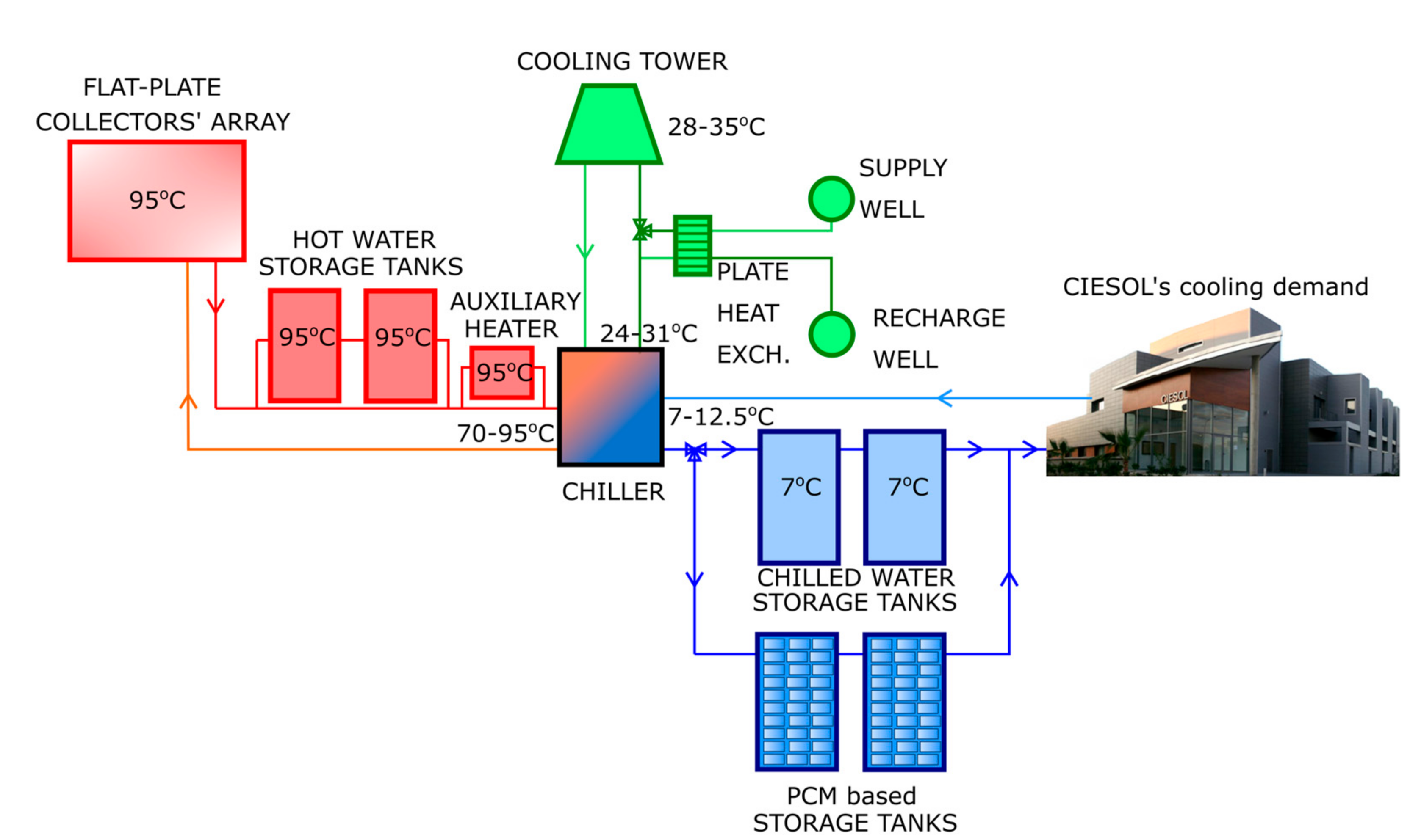
:1. Introduction
2. Methods
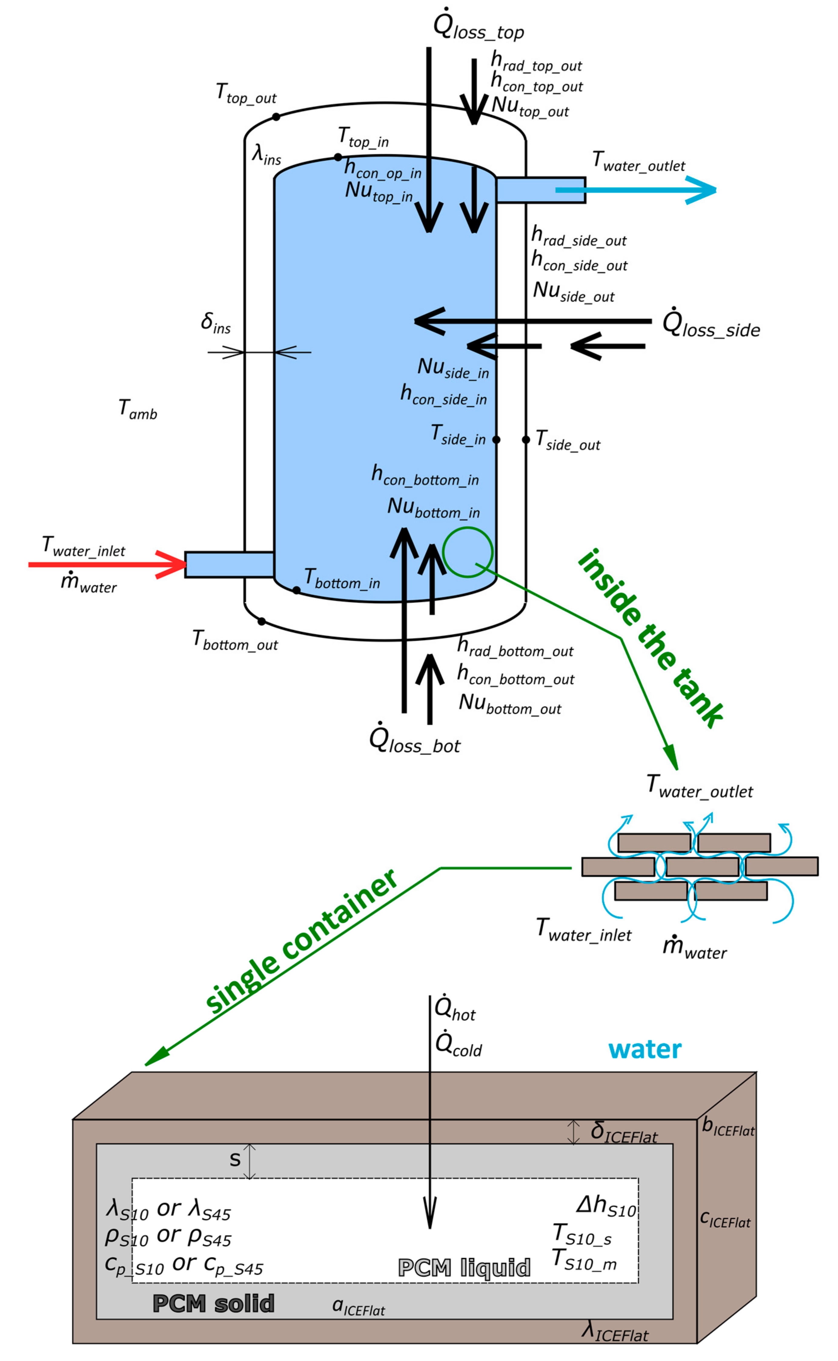
Description of the Heat Transfer Model
- – the thermal conductivity of storage tanks’ insulation is 0.034 W/(m·K),
- – the convective heat transfer coefficient on the PCM side is replaced by thermal conductivity for the liquid and solid phase (described below),
- – the ICEFlat container heat transfer coefficient equals 13 W/(m·K).
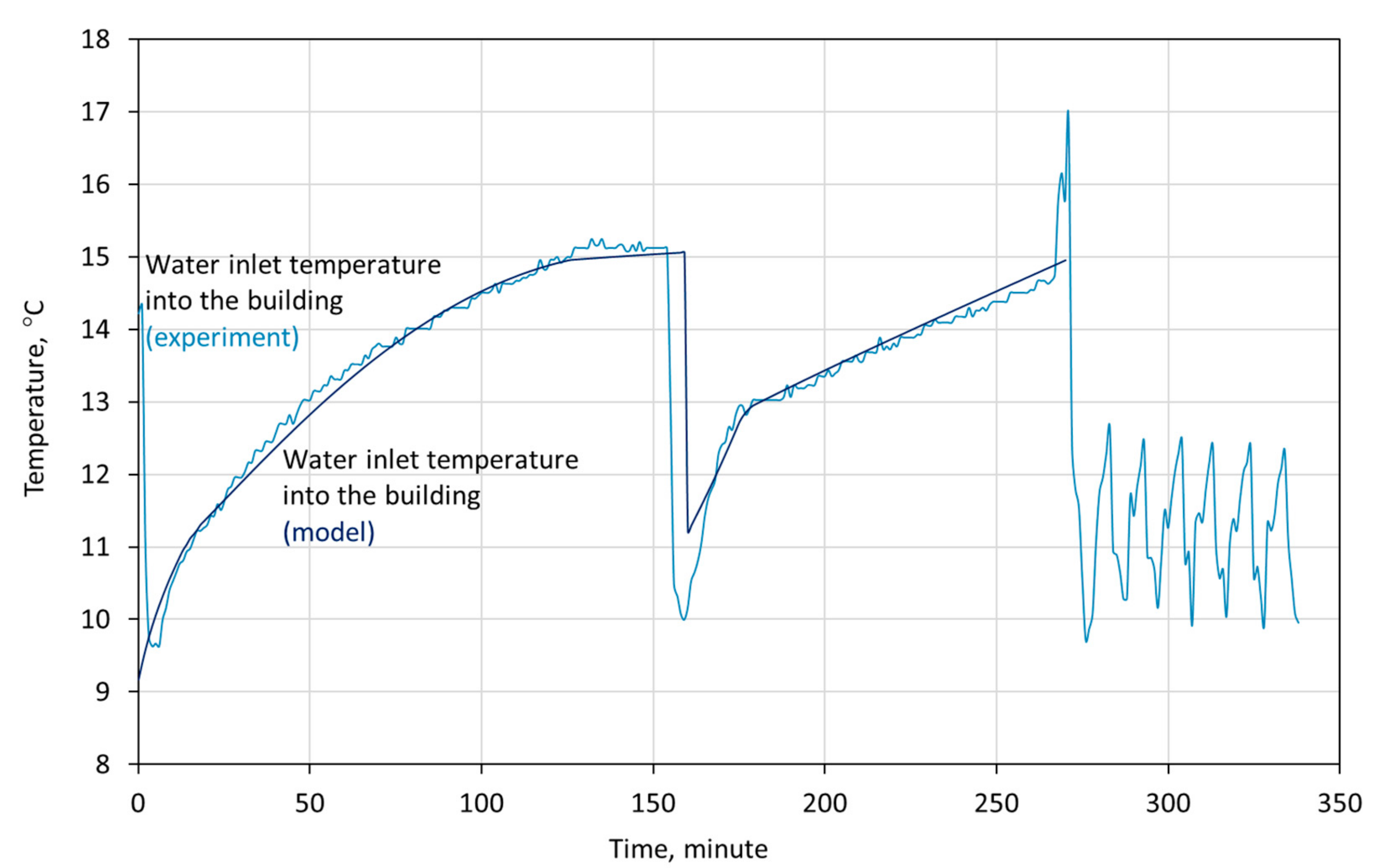
3. Model Validation
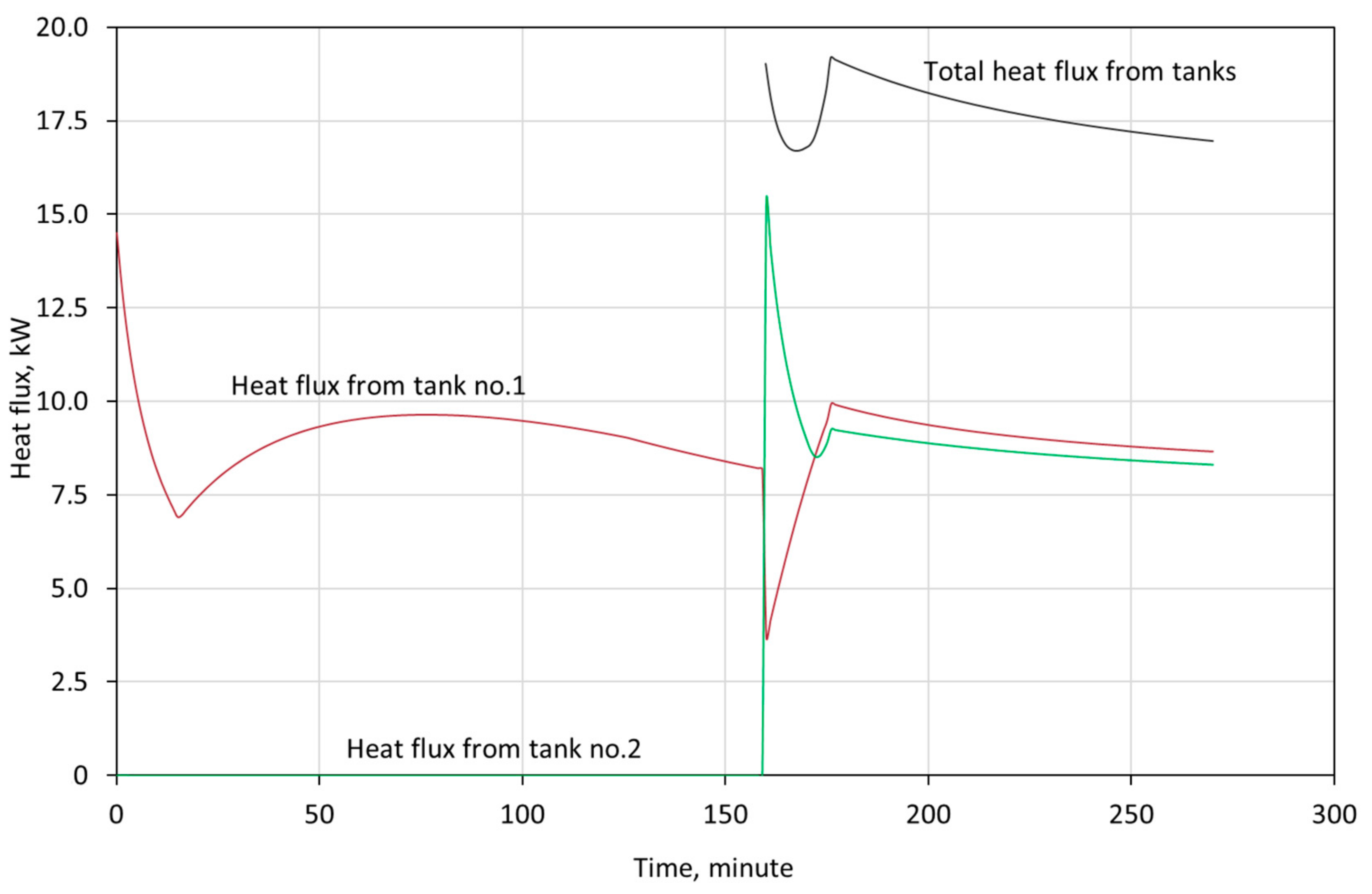
- the tanks operate in a cascade configuration, which means that the first tank is discharged first. When the temperature of outflowing water reaches 15 °C, the water flow is redirected into tank 2, and the temperature of water outflowing from tank 1 is the same as the temperature of water flowing into tank 2,
- the initial temperature of the PCMs in both tanks, according to the sensors located in the tanks, is equal to 6.5 °C,
- the ambient temperature is equal to 25.0 °C,
- the water flow rate is 7 m3/h,
- the temperature of the water flowing into the tank is taken from the experiment and is shown in Figure 3.
4. Discussion
5. Conclusions
Author Contributions
Funding
Conflicts of Interest
References
- Ramakrishnan, S.; Sanjayan, J.; Wang, X. Experimental research on using form-stable PCM-integrated cementitious composite for reducing overheating in buildings. Buildings 2019, 9, 57. [Google Scholar] [CrossRef] [Green Version]
- Iten, M.; Liu, S.; Shukla, A. A review on the air-PCM-TES application for free cooling and heating in the buildings. Renew. Sustain. Energy Rev. 2016, 61, 175–186. [Google Scholar] [CrossRef]
- Beaudin, M.; Zareipour, H. A Review of PCM Energy Storage Technology Used in Buildings for the Global Warming Solution. In Energy Solutions to Combat Global Warming; Springer: Cham, Switzerland, 2017; Volume 33, ISBN 978-3-319-26948-1. [Google Scholar]
- Real, A.; García, V.; Domenech, L.; Renau, J.; Montés, N.; Sánchez, F. Improvement of a heat pump based HVAC system with PCM thermal storage for cold accumulation and heat dissipation. Energy Build. 2014, 83, 108–116. [Google Scholar] [CrossRef]
- Behi, M.; Mirmohammadi, S.A.; Ghanbarpour, M.; Behi, H.; Palm, B. Evaluation of a novel solar driven sorption cooling/heating system integrated with PCM storage compartment. Energy 2018, 164, 449–464. [Google Scholar] [CrossRef]
- Ramakrishnan, S.; Wang, X.; Sanjayan, J.; Wilson, J. Experimental and Numerical Study on Energy Performance of Buildings Integrated with Phase Change Materials. Energy Procedia 2017, 105, 2214–2219. [Google Scholar] [CrossRef]
- Kong, L.B.; Li, T.; Hng, H.H.; Boey, F.; Zhang, T.; Li, S. Preface. In Waste Energy Harvesting; Lecture Notes in Energy Series; Springer: Berlin/Heidelberg, Germany, 2014; Volume 24, ISBN 9783642546341. [Google Scholar]
- Bakoń, T.; Obstawski, P.; Kozikowska, A. Modelling of Heat Storage Using Phase Change Material Tank. In Renewable Energy Sources: Engineering, Technology, Innovation; Springer: Cham, Switzerland, 2020; pp. 809–816. [Google Scholar] [CrossRef]
- Ibáñez, M.; Cabeza, L.F.; Solé, C.; Roca, J.; Nogués, M. Modelization of a water tank including a PCM module. Appl. Therm. Eng. 2006, 26, 1328–1333. [Google Scholar] [CrossRef]
- Noro, M.; Lazzarin, R.M.; Busato, F. Solar cooling and heating plants: An energy and economic analysis of liquid sensible vs phase change material (PCM) heat storage. Int. J. Refrig. 2014, 39, 104–116. [Google Scholar] [CrossRef]
- Lee, Y.T.; Kim, M.H.; Lee, S.S.; Gim, J.; Chung, J.D. Numerical analysis in a full-scale thermal energy storage tank with dual PCM capsules. Energy Build. 2019, 204, 109410. [Google Scholar] [CrossRef]
- Mohammadnejad, F.; Hossainpour, S. A CFD modeling and investigation of a packed bed of high temperature phase change materials (PCMs) with different layer configurations. J. Energy Storage 2020, 28, 101209. [Google Scholar] [CrossRef]
- Bourne, S.; Novoselac, A. Compact PCM-based thermal stores for shifting peak cooling loads. Build. Simul. 2015, 8, 673–688. [Google Scholar] [CrossRef]
- Wang, Z.; Zhang, H.; Dou, B.; Zhang, G.; Wu, W. Influence of inlet structure on thermal stratification in a heat storage tank with PCMs: CFD and experimental study. Appl. Therm. Eng. 2019, 162. [Google Scholar] [CrossRef]
- Aziz, S.; Amin, N.A.M.; Abdul Majid, M.S.; Belusko, M.; Bruno, F. CFD simulation of a TES tank comprising a PCM encapsulated in sphere with heat transfer enhancement. Appl. Therm. Eng. 2018, 143, 1085–1092. [Google Scholar] [CrossRef]
- Belmonte, J.F.; Eguía, P.; Molina, A.E.; Almendros-Ibáñez, J.A.; Salgado, R. A simplified method for modeling the thermal performance of storage tanks containing PCMs. Appl. Therm. Eng. 2016, 95, 394–410. [Google Scholar] [CrossRef]
- Gallego, A.J.; Ruíz-Pardo, A.; Cerezuela-Parish, A.; Sánchez, J.; Martín-Macareno, C.; Cabeza, L.F.; Camacho, E.F.; Oró, E. Mathematical modeling of a PCM storage tank in a solar cooling plant. Sol. Energy 2013, 93, 1–10. [Google Scholar] [CrossRef]
- Lin, W.; Ma, Z.; McDowell, C.; Baghi, Y.; Banfield, B. Optimal design of a thermal energy storage system using phase change materials for a net-zero energy Solar Decathlon house. Energy Build. 2020, 208, 109626. [Google Scholar] [CrossRef]
- Barragan-Cervera, Á.; Domenech, L.; Fernando, S.; Maiorino, A.; Aprea, C. Modeling of a PCM TES Tank Used as an Alternative Heat Sink for a Water Chiller. Analysis of Performance and Energy Savings. Energies 2019, 12, 3652. [Google Scholar]
- Carmona, M.; Rincón, A.; Gulfo, L. Energy and exergy model with parametric study of a hot water storage tank with PCM for domestic applications and experimental validation for multiple operational scenarios. Energy Convers. Manag. 2020, 222, 113189. [Google Scholar] [CrossRef]
- Roccamena, L.; El Mankibi, M.; Stathopoulos, N. Development and validation of the numerical model of an innovative PCM based thermal storage system. J. Energy Storage 2019, 24, 100740. [Google Scholar] [CrossRef]
- Raul, A.; Jain, M.; Gaikwad, S.; Saha, S.K. Modelling and experimental study of latent heat thermal energy storage with encapsulated PCMs for solar thermal applications. Appl. Therm. Eng. 2018, 143, 415–428. [Google Scholar] [CrossRef]
- Jokiel, M.; Kauko, H.; Schlemminger, C.; Hafner, A.; Claussen, I.C. Phase change material thermal energy storage for a large ammonia chiller/heat pump system. In Proceedings of the 7th Conference on Ammonia and CO2 Refrigeration Technology, Ohrid, Macedonia, 11–13 May 2017; pp. 179–186. [Google Scholar] [CrossRef]
- Jokiel, M. Development and Performance Analysis of an Object-Oriented Model for Phase Change Material Thermal Storage; Project Work; SINTEF Energy Research: Trondheim, Norway, 2016. [Google Scholar]
- Mousa, H.; Naser, J.; Houche, O. Using PCM as energy storage material in water tanks: Theoretical and experimental investigation. J. Energy Storage 2019, 22, 1–7. [Google Scholar] [CrossRef]
- Abdelsalam, M.Y.; Teamah, H.M.; Lightstone, M.F.; Cotton, J.S. Hybrid thermal energy storage with phase change materials for solar domestic hot water applications: Direct versus indirect heat exchange systems. Renew. Energy 2020, 147, 77–88. [Google Scholar] [CrossRef]
- Singh, S.P.; Bhat, V. Performance evaluation of dual phase change material gypsum board for the reduction of temperature swings in a building prototype in composite climate. Energy Build. 2018, 159, 191–200. [Google Scholar] [CrossRef]
- Lakhdari, Y.A.; Chikh, S.; Campo, A. Analysis of the thermal response of a dual phase change material embedded in a multi-layered building envelope. Appl. Therm. Eng. 2020, 179, 115502. [Google Scholar] [CrossRef]
- Wang, G.; Xu, C.; Wei, G.; Du, X. Numerical study of a novel dual-PCM thermal energy storage structure filled with inorganic salts and metal alloy as the PCMs. Energy Procedia 2019, 158, 4423–4428. [Google Scholar] [CrossRef]
- Wang, D.; Liu, H.; Liu, Y.; Xu, T.; Wang, Y.; Du, H.; Wang, X.; Liu, J. Frost and High-temperature resistance performance of a novel dual-phase change material flat plate solar collector. Sol. Energy Mater. Sol. Cells 2019, 201. [Google Scholar] [CrossRef]
- Batlles, F.J.; Gil, B.; Ushak, S.; Kasperski, J.; Luján, M.; Maldonado, D.; Nemś, M.; Nemś, A.; Puertas, A.M.; Romero-Cano, M.S.; et al. Development and Results from Application of PCM-Based Storage Tanks in a Solar Thermal Comfort System of an Institutional Building—A Case Study. Energies 2020, 13, 3877. [Google Scholar] [CrossRef]
- Rosiek, S.; Batlles, F.J. Reducing a solar-assisted air-conditioning system’s energy consumption by applying real-time occupancy sensors and chilled water storage tanks throughout the summer: A case study. Energy Convers. Manag. 2013, 76, 1029–1042. [Google Scholar] [CrossRef]
- Rosiek, S.; Batlles, F.J. Renewable energy solutions for building cooling, heating and power system installed in an institutional building: Case study in southern Spain. Renew. Sustain. Energy Rev. 2013, 26, 147–168. [Google Scholar] [CrossRef]
- Rosiek, S.; Batlles Garrido, F.J. Performance evaluation of solar-assisted air-conditioning system with chilled water storage (CIESOL building). Energy Convers. Manag. 2012, 55, 81–92. [Google Scholar] [CrossRef]
- Gil, B.; Rosiek, S.; Kasperski, J.; Nemś, M.; Nemś, A. Analysis of heat gains in a real research building: The difference in the need of air conditioning systems for various locations around the world. In Proceedings of the ECOS 2019—32nd International Conference on Efficiency, Cost, Optimization, Simulation and Environmental Impact of Energy Systems, Wrocław, Poland, 23–28 June 2019; pp. 2559–2570. [Google Scholar]
- Nems, A.; Nems, M.; Rosiek, S.; Puertas, A.M.; Gil, B.; Kasperski, J.; Batlles, F.J. Modeling of the discharging process of a heat storage tank filled with PCM to cover the heat demand of a building. In Proceedings of the EA SHC International Conference onSolar Heating and Cooling for Buildings and Industry, Santiago, Chile, 3–7 November 2019; pp. 1393–1404. [Google Scholar] [CrossRef]
- Kostowski, E. Zbiór Zadań z Przepływu Ciepła; Wydawnictwo Politechniki Śląskiej: Gliwice, Poland, 2006; ISBN 83-88000-18-7. [Google Scholar]


| PCM | Phase Change Temperature | Density | Latent Heat Capacity | Specific Heat Capacity | Thermal Conductivity | Max. Operating Temperature |
|---|---|---|---|---|---|---|
| °C | kg/m3 | kJ/kg | kJ/(kg·K) | W/(m·K) | °C | |
| S10 | 10 | 1.470 | 155 | 1.90 | 0.43 | 60 |
| S46 | 46 | 1.587 | 210 | 2.41 | 0.45 | 56 |
| PCM\Proportions | 50–50% | 40–60% | 30–70% | 20–80% | 15–85% | 12–88% | 10–90% |
|---|---|---|---|---|---|---|---|
| S46 | 99 | 79 | 59 | 40 | 30 | 24 | 20 |
| S10 | 99 | 119 | 139 | 158 | 168 | 174 | 178 |
Publisher’s Note: MDPI stays neutral with regard to jurisdictional claims in published maps and institutional affiliations. |
© 2020 by the authors. Licensee MDPI, Basel, Switzerland. This article is an open access article distributed under the terms and conditions of the Creative Commons Attribution (CC BY) license (http://creativecommons.org/licenses/by/4.0/).
Share and Cite
Nemś, A.; Puertas, A.M. Model for the Discharging of a Dual PCM Heat Storage Tank and Its Experimental Validation. Energies 2020, 13, 5687. https://doi.org/10.3390/en13215687
Nemś A, Puertas AM. Model for the Discharging of a Dual PCM Heat Storage Tank and Its Experimental Validation. Energies. 2020; 13(21):5687. https://doi.org/10.3390/en13215687
Chicago/Turabian StyleNemś, Artur, and Antonio M. Puertas. 2020. "Model for the Discharging of a Dual PCM Heat Storage Tank and Its Experimental Validation" Energies 13, no. 21: 5687. https://doi.org/10.3390/en13215687