Design of an Optimized Thermal Management System for Li-Ion Batteries under Different Discharging Conditions


Abstract
:1. Introduction
2. Thermal Behavior Study and Analysis
2.1. Case Study for Temperature Rise under Different Discharge Rates
2.2. Thermal Runaway
3. Thermal Management Techniques
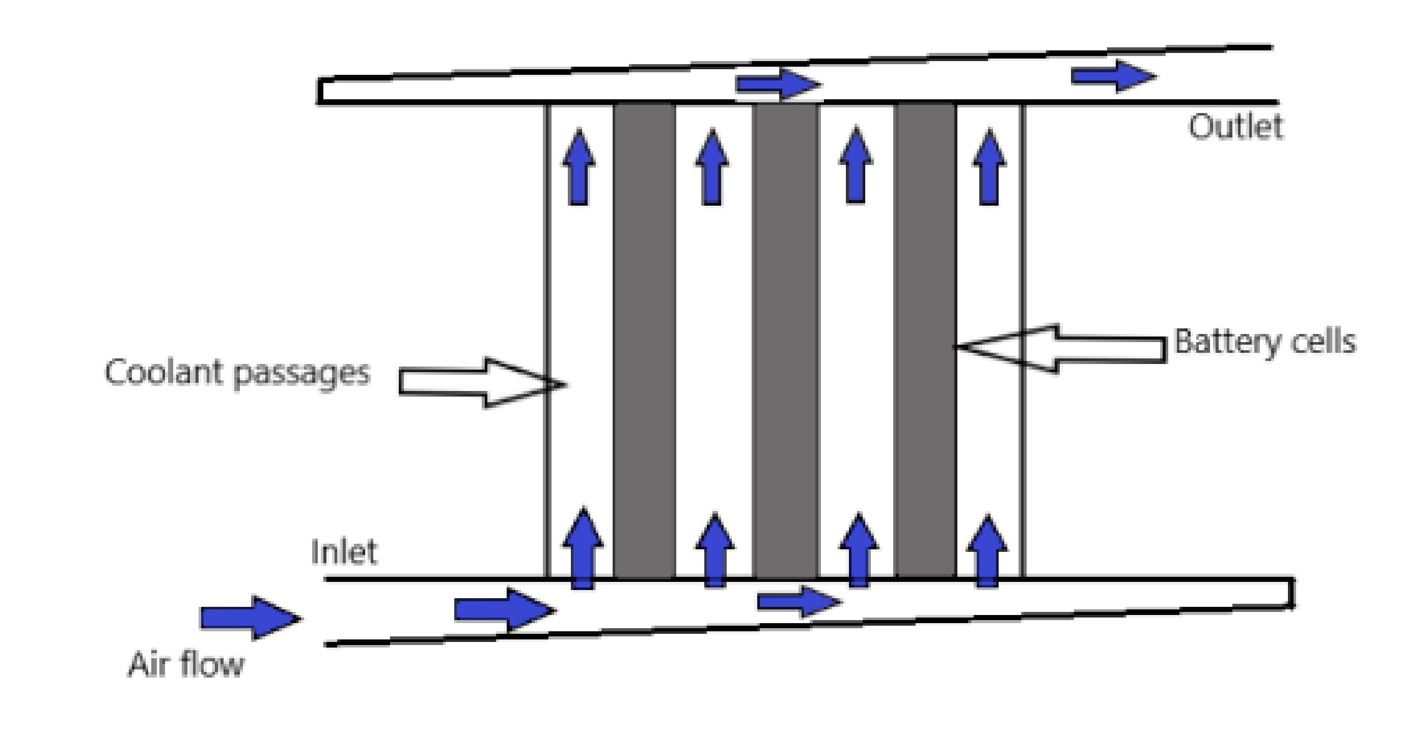
3.1. Air Cooling
3.2. Liquid Cooling
3.3. Refrigerant Cooling
3.4. Phase Change Material
4. Modeling Aspects
4.1. Air Cooling
4.2. Liquid Cooling
5. Results and Discussions
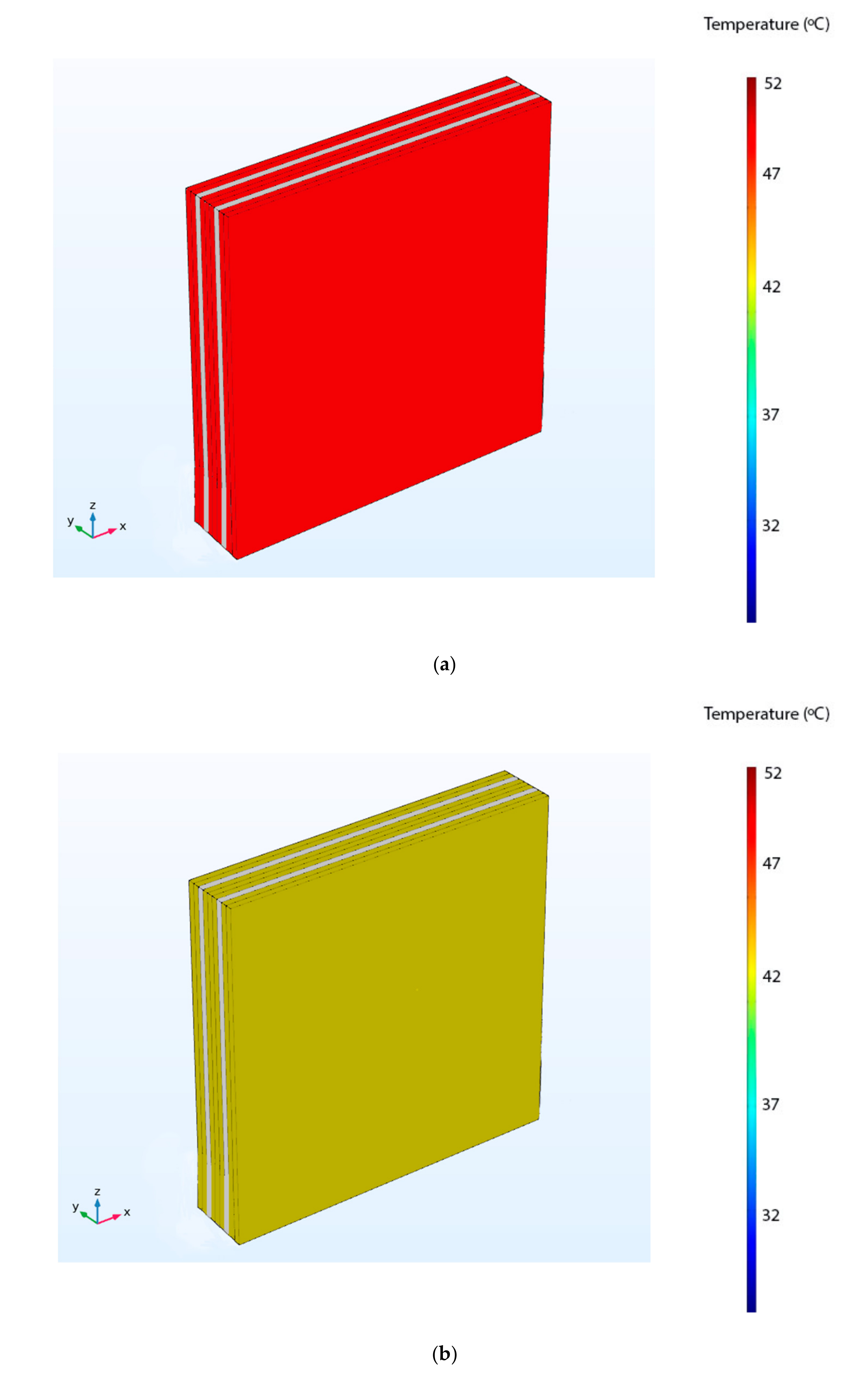
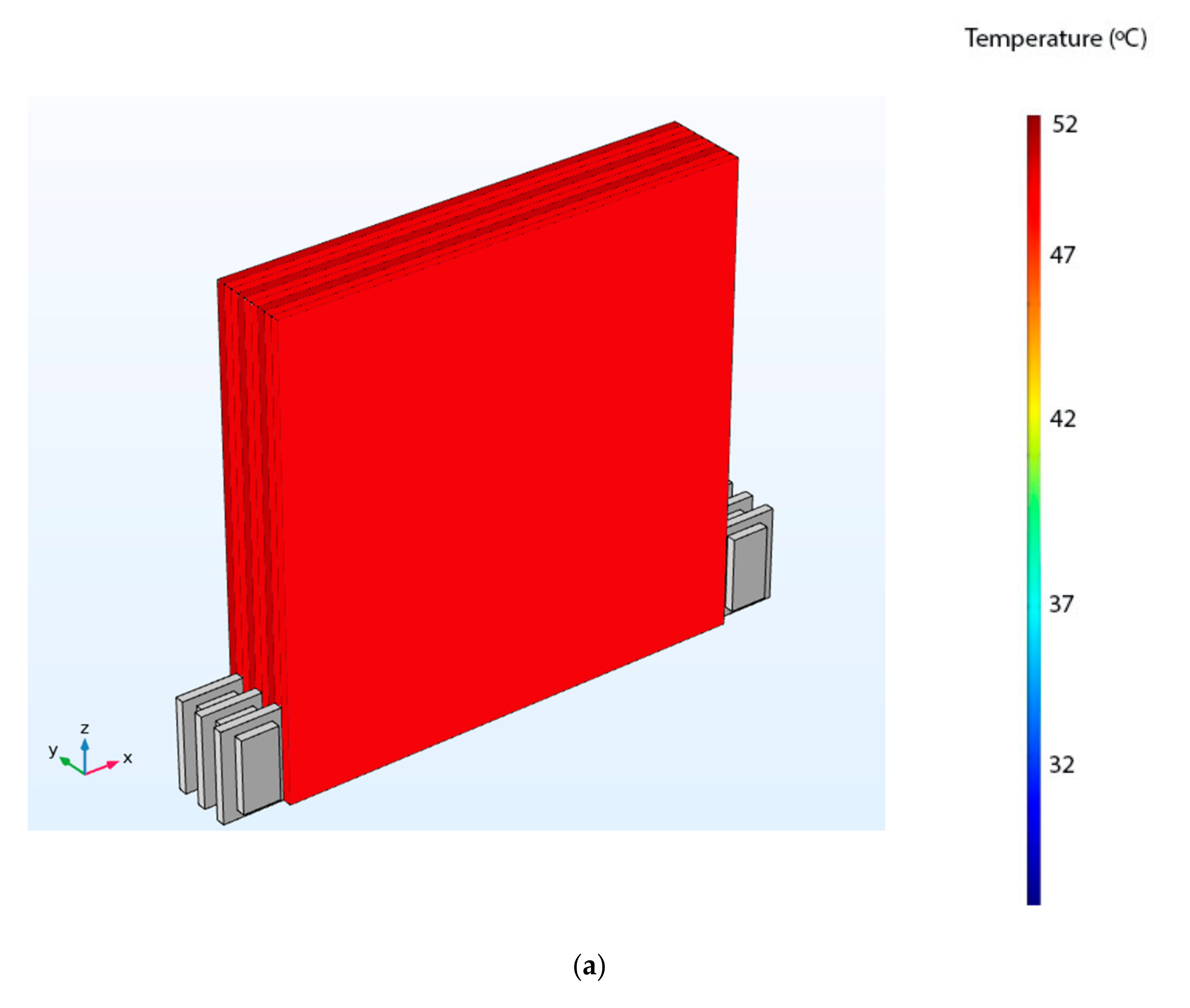
5.1. Air Cooling
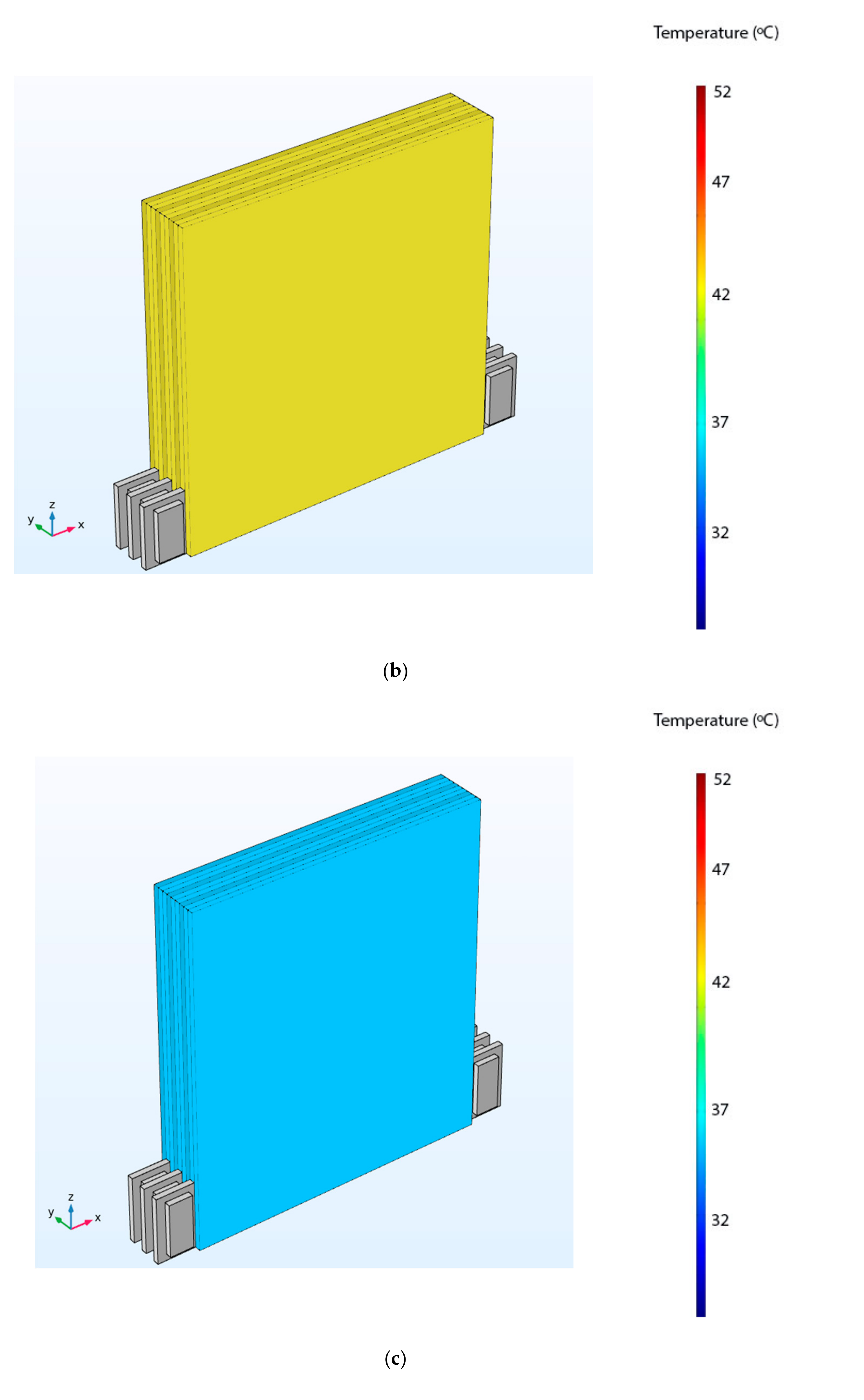
5.2. Liquid Cooling
6. Proposed Modified Liquid Cooling Technique- Immersion Based Liquid Cooling
7. Performance Analysis of Immersion Based Liquid Cooling Technique
8. Conclusions
Author Contributions
Funding
Acknowledgments
Conflicts of Interest
References
- Lu, L.; Han, X.; Li, J.; Hua, J.; Ouyang, M. A review on the key issues for lithium-ion battery management in electric vehicles. J. Power Sources 2013, 226, 272–288. [Google Scholar] [CrossRef]
- Yuksel, T.; Litster, S.; Viswanathan, V.; Michalek, J.J. Plug-in hybrid electric vehicle LiFePO4 battery life implications of thermal management, driving conditions, and regional climate. J. Power Sources 2017, 338, 49–64. [Google Scholar] [CrossRef] [Green Version]
- Friesen, A.; Horsthemke, F.; Mönnighoff, X.; Brunklaus, G.; Krafft, R.; Börner, M.; Risthaus, T.; Winter, M.; Schappacher, F.M. Impact of cycling at low temperatures on the safety behaviour of 18,650-type Lithium ion cells: Combined study of mechanical and thermal abuse testing accompanied by post-mortem analysis. J. Power Sources 2016, 334, 1–11. [Google Scholar] [CrossRef]
- Feng, X.; Sun, J.; Ouyang, M.; Wang, F.; He, X.; Lu, L.; Peng, H. Characterization of penetration induced thermal runaway propagation process within a large format lithium ion battery module. J. Power Sources 2015, 275, 261. [Google Scholar] [CrossRef]
- Chen, D.; Jiang, J.; Kim, G.; Yang, C.; Pesaran, A. Comparison of different cooling methods for lithium ion battery cells. J. Power Sources 2016, 94, 846–854. [Google Scholar] [CrossRef] [Green Version]
- Zolot, M.; Pesaran, A.A.; Mihalic, M. Thermal Evaluation of Toyota Prius Battery Pack; Technical Report, SAE Technical Paper; SAE International: Atlanta, GA, USA, 2002. [Google Scholar] [CrossRef] [Green Version]
- Zolot, M.D.; Kelly, K.; Keyser, M.; Mihalic, M.; Pesaran, A.; Hieronymus, A. Thermal evaluation of the Honda Insight battery pack. In Proceedings of the Intersociety Energy Conversion Engineering Conference SAE, Savannah, Georgia, 29 July–2 August 2001; pp. 923–928. [Google Scholar]
- Kelly, K.J.; Mihalic, M.; Zolot, M. Battery usage and thermal performance of the Toyota Prius and Honda Insight during chassis dynamometer testing. In Proceedings of the IEEE Battery Conference, Long Beach, CA, USA, 18 January 2002; pp. 247–252. [Google Scholar] [CrossRef]
- Wang, Q.; Ping, P.; Zhao, X.; Chu, G.; Sun, J.; Chen, C. Thermal runaway caused fire and explosion of Lithium ion battery. J. Power Sources 2012, 208, 210–224. [Google Scholar] [CrossRef]
- Pesaran, A.A.; Burch, S.; Keyser, M. An approach for designing thermal management systems for electric and hybrid vehicle battery packs. Veh. Therm. Manag. Syst. 1999, 4, 24–27. [Google Scholar]
- Kim, G.; Pesaran, A.A. Battery thermal management design modelling. J. World Electr. Veh. 2007, 1, 126–133. [Google Scholar] [CrossRef] [Green Version]
- Chacko, S.; Charmer, S. Lithium-ion pack thermal modelling and evaluation of indirect liquid cooling for electric vehicle battery thermal management. In Innovations in Fuel Economy and Sustainable Road Transport; Woodhead Publishing: Cambridge, UK, 2011; pp. 13–21. [Google Scholar] [CrossRef]
- Yeow, K.; Teng, H.; Thelliez, M.; Tan, E. Comparative study on thermal behaviour of lithium-ion battery systems with indirect air cooling and indirect liquid cooling. In Proceedings of the ASME/ISCIE 2012 International Symposium on Flexible Automation, St. Louis, MO, USA, 18–20 June 2012; pp. 585–591. [Google Scholar] [CrossRef]
- Wu, M.S.; Liu, K.; Wang, Y.Y.; Wan, C.C. Heat dissipation design for lithium-ion batteries. J. Power Sources 2002, 109, 160–166. [Google Scholar] [CrossRef]
- Peng, X.; Cui, X.; Liao, X.; Garg, A. A Thermal investigation and optimization of an air-cooled lithium ion battery pack. Energies 2020, 13, 2956. [Google Scholar] [CrossRef]
- Rao, Z.; Wang, S. A review of power battery thermal energy management. Renew. Sustain. Energy Rev. 2011, 15, 4554–4571. [Google Scholar] [CrossRef]
- Bandhauer, T.M.; Garimella, S.; Fuller, T.F. A critical review of thermal issues in lithium-ion batteries. J. Electrochem. Soc. 2011, 15, 1–25. [Google Scholar] [CrossRef]
- Xia, B.; Liu, Y.; Huang, R.; Yang, Y.; Lai, Y.; Zheng, W.; Wang, H.; Wang, W.; Wang, M. Thermal analysis and improvements of the power battery pack with liquid cooling for electric vehicles. Energies 2019, 12, 3045. [Google Scholar] [CrossRef] [Green Version]
- Hong, S.H.; Jang, D.S.; Park, S.; Yun, S.; Kim, Y. Thermal performance of direct two-phase refrigerant cooling for lithium-ion batteries in electric vehicles. Appl. Therm. Eng. 2020, 173, 115213. [Google Scholar] [CrossRef]
- Sundin, D.W.; Sponholtz, S. Thermal Management of Li-Ion Batteries with Single-Phase Liquid Immersion Cooling. IEEE Open J. Veh. Technol. 2020, 1, 82–92. [Google Scholar] [CrossRef]
- Bernardi, D.; Pawlikowski, E.; Newman, J. A General Energy Balance for Battery Systems. J. Electrochem. Soc. 1985, 5, 132. [Google Scholar] [CrossRef] [Green Version]
- Mills, A.; Al-Hallaj, S. Simulation of passive thermal management system for lithium-ion battery packs. J. Power Sources 2005, 141, 307–315. [Google Scholar] [CrossRef]
- Eddahech, A.; Briat, O.; Vinassa, J.-M. Thermal characterization of a high-power lithium-ion battery: Potentiometric and calorimetric measurement of entropy changes. J. Energy 2013, 61, 432–439. [Google Scholar] [CrossRef]
- Shah, K.; Chalise, D.; Jain, A. Experimental and theoretical analysis of a method to predict thermal runaway in Li-ion cells. J. Power Sources 2016, 330, 167–174. [Google Scholar] [CrossRef] [Green Version]
- Golubkov, A.W.; Fuchs, D.; Wagner, J.; Wiltsche, H.; Stangl, C.; Fauler, G.; Voitic, G.; Thaler, A.; Hacker, V. Thermal-runaway experiments on consumer Li-ion batteries with metal-oxide and olivine-type cathodes. RSC Adv. 2014, 4, 3633–3642. [Google Scholar] [CrossRef] [Green Version]
- Drake, S.J.; Martin, M.; Wetz, D.A.; Ostanek, J.K.; Miller, S.P.; Heinzel, J.M.; Jain, A. Heat generation rate measurement in a Li-ion cell at large C-rates through temperature and heat flux measurements. J. Power Sources 2015, 285, 266–273. [Google Scholar] [CrossRef]
- Jhu, C.Y.; Wang, Y.W.; Shu, C.M.; Chang, J.C.; Wu, H.C. Thermal explosion hazards on 18,650 lithium ion batteries with a VSP2 adiabatic calorimeter. J. Hazard. Mater. 2011, 192, 99–107. [Google Scholar] [CrossRef] [PubMed]
- Jhu, C.Y.; Wang, Y.W.; Wen, C.Y.; Shu, C.M. Thermal runaway potential of LiCoO2 and Li(Ni1/3Co1/3Mn1/3)O2 batteries determined with adiabatic calorimetry methodology. Appl. Energy 2012, 100, 127–131. [Google Scholar] [CrossRef]
- Chen, W.C.; Wang, Y.W.; Shu, C.M. Adiabatic calorimetry test of the reaction kinetics and self-heating model for 18650 Li-ion cells in various states of charge. J. Power Sources 2016, 318, 200–209. [Google Scholar] [CrossRef]
- Cheng, X.; Li, T.; Ruan, X.; Wang, Z. Thermal Runaway Characteristics of a Large Format Lithium-Ion Battery Module. Energies 2019, 12, 3099. [Google Scholar] [CrossRef] [Green Version]
- Jindal, P.; Bhattacharya, J. Review—Understanding the Thermal Runaway Behaviour of Li-Ion Batteries through Experimental Techniques. J. Electrochem. Soc. 2019, 166, 10. [Google Scholar] [CrossRef]
- Feng, X.; Ouyang, M.; Liu, X.; Lu, L.; Xia, Y.; He, X. Thermal runaway mechanism of lithium ion battery for electric vehicles: A review. Energy Storage Mater. 2018, 10, 246–267. [Google Scholar] [CrossRef]
- Ouyang, D.; Chen, M.; Liu, J.; Wei, R.; Weng, J.; Wang, J. Investigation of a commercial lithium-ion battery under overcharge/over-discharge failure conditions. RSC Adv. 2018, 8, 33414–33424. [Google Scholar] [CrossRef] [Green Version]
- Jaguemont, J.; Boulon, L.; Dubé, Y. A Comprehensive Review on Lithium Ion Batteries used in Hybrid and Electric vehicle under Cold Temperature. Appl. Energy 2016, 164, 99–114. [Google Scholar] [CrossRef]
- Jeevarajan, J. Safety of Commercial Lithium-Ion Cells and Batteries. In Lithium-Ion Batteries: Advances and Applications; Elsevier B.V.: Amsterdam, The Netherlands, 2014; pp. 384–407. [Google Scholar] [CrossRef]
- Xia, L.; Zhu, L.; Haiyan, Z.; Ai, X. A positive-temperature-coefficient electrode with thermal protection mechanism for rechargeable lithium batteries. Chin. Sci. Bull. 2012, 57, 4205–4209. [Google Scholar] [CrossRef] [Green Version]
- Lopez, C.F.; Jeevarajan, J.A.; Mukherjee, P.P. Experimental Analysis of Thermal Runaway and Propagation in Lithium-Ion Battery Modules. J. Electrochem. Soc. 2015, 162, 9. [Google Scholar] [CrossRef]
- Wilke, S.; Schweitzer, B.; Khateeb, S.; Al-Hallaj, S. Preventing thermal runaway propagation in lithium ion battery packs using a phase change composite material: An experimental study. J. Power Sources 2017, 340, 51–59. [Google Scholar] [CrossRef]
- Sabbah, R.; Kizilel, R.; Selman, J.R.; Al-Hallaj, S. Active (air-cooled) vs. passive (phase change material) thermal management of high-power lithium-ion packs: Limitation of temperature rise and uniformity of temperature distribution. J. Power Sources 2008, 182, 630–638. [Google Scholar] [CrossRef]
- Pesaran, A.A. Battery thermal models for hybrid vehicle simulations. J. Power Sources 2002, 110, 377–382. [Google Scholar] [CrossRef]
- Li, X.; He, F.; Zhang, G.; Huang, Q.; Zhou, D. Experiment and simulation for pouch battery with silica cooling plates and copper mesh-based air-cooling thermal management system. Appl. Therm. Eng. 2019, 146, 866–880. [Google Scholar] [CrossRef]
- Chen, S.C.; Wan, C.C.; Wang, Y.Y. Thermal analysis of lithium-ion batteries. J. Power Sources 2005, 140, 111–124. [Google Scholar] [CrossRef]
- Mohammadian, S.K.; Zhang, Y. Thermal management optimization of an air-cooled Li-ion battery module using pin-fin heat sinks for hybrid electric vehicles. J. Power Sources 2015, 273, 431–439. [Google Scholar] [CrossRef]
- Park, S.; Jung, D. Battery cell arrangement and heat transfer fluid effects on the parasitic power consumption and the cell temperature distribution in a hybrid electric vehicle. J. Power Sources 2013, 227, 191–198. [Google Scholar] [CrossRef]
- Menale, C.; D’Annibale, F.; Mazzarotta, B.; Bubbico, R. Thermal management of lithium-ion batteries: An experimental investigation. Energy 2019, 182, 57–71. [Google Scholar] [CrossRef]
- Yuan, H.; Wang, L.; Wang, L. Battery thermal management system with liquid cooling and heating in electric vehicles. J. Automot. Saf. Energy 2012, 3, 371–380. [Google Scholar] [CrossRef]
- Patil, M.S.; Panchal, S.; Kim, N.; Lee, M.-Y. Cooling Performance Characteristics of 20 Ah Lithium-Ion Pouch Cell with Cold Plates along Both Surfaces. Energies 2018, 11, 2550. [Google Scholar] [CrossRef] [Green Version]
- Zhao, J.; Rao, Z.; Li, Y. Thermal performance of mini-channel liquid cooled cylinder-based battery thermal management for cylindrical lithium-ion power battery. Energy Convers. Manag. 2015, 103, 157–165. [Google Scholar] [CrossRef]
- Lan, C.; Xu, J.; Qiao, Y.; Ma, Y. Thermal management for high power lithium-ion battery by mini channel aluminium tubes. Appl. Therm. Eng. 2016, 101, 284–292. [Google Scholar] [CrossRef] [Green Version]
- An, Z.; Jia, L.; Li, X.; Ding, Y. Experimental investigation on lithium-ion battery thermal management based on flow boiling in mini-channel. Appl. Therm. Eng. 2017, 117, 534–543. [Google Scholar] [CrossRef]
- Deng, T.; Zhang, G.; Ran, Y. Study on thermal management of rectangular li-ion battery with serpentine-channel cold plate. Int. J. Heat Mass Transf. 2018, 125, 143–152. [Google Scholar] [CrossRef]
- Zhao, C.; Cao, W.; Dong, T.; Jiang, F. Thermal behaviour study of discharging/charging cylindrical lithium-ion battery module cooled by channelled liquid flow. Int. J. Heat Mass Transf. 2018, 120, 751–762. [Google Scholar] [CrossRef]
- Zhao, C.; Sousa, A.C.M.; Jiang, F. Minimization of thermal non-uniformity in lithium-ion battery pack cooled by channelled liquid flow. Int. J. Heat Mass Transf. 2019, 129, 660–670. [Google Scholar] [CrossRef]
- Huo, Y.; Rao, Z.; Liu, X.; Zhao, J. Investigation of power battery thermal management by using mini-channel cold plate. Energy Convers. Manag. 2015, 89, 387–395. [Google Scholar] [CrossRef]
- Yang, X.H.; Tan, S.C.; Liu, J. Thermal management of Li-ion battery with liquid metal. Energy Convers. Manag. 2016, 117, 577–585. [Google Scholar] [CrossRef]
- Kim, J.; Oh, J.; Lee, H. Review on battery thermal management system for electric vehicles. Appl. Therm. Eng. 2019, 149, 192–212. [Google Scholar] [CrossRef]
- Krüger, I.L.; Limperich, D. Energy Consumption of Battery Cooling in Hybrid Electric Vehicles. In Proceedings of the International Refrigeration and Air Conditioning Conference, West Lafayette, IN, USA, 16–19 July 2012. [Google Scholar]
- Gillet, T.; Andres, E.; El-bakkali, A.; Lemort, V.; Rulliere, R.; Haberschill, P. Sleeping evaporator and refrigerant maldistribution: An experimental investigation in an automotive multi-evaporator air-conditioning and battery cooling system. Int. J. Refrig. 2018, 90, 119–131. [Google Scholar] [CrossRef]
- Hémery, C.V.; Pra, F.; Robin, J.F.; Marty, P. Experimental performances of a battery thermal management system using phase change material. J. Power Sources 2014, 270, 349–358. [Google Scholar] [CrossRef]
- Karimi, G.; Azizi, M.; Babapoor, A. Experimental study of a cylindrical lithium ion battery thermal management using phase change material composites. J. Energy Storage 2016, 8, 168–174. [Google Scholar] [CrossRef]
- Samimi, F.; Babapoor, A.; Azizi, M.; Karimi, G. Thermal management analysis of a Li-ion battery cell using phase change material loaded with carbon fibres. Energy 2016, 96, 355–371. [Google Scholar] [CrossRef]
- Lv, Y.; Yang, X.; Li, X.; Zhang, G.; Wang, Z.; Yang, C. Experimental study on a novel battery thermal management technology based on low density polyethylene-enhanced composite phase change materials coupled with low fins. Appl. Energy 2016, 178, 376–382. [Google Scholar] [CrossRef]
- Park, H. A design of air flow configuration for cooling lithium ion battery in hybrid electric vehicles. J. Power Sources 2013, 239, 30–36. [Google Scholar] [CrossRef]
- Siruvuri, S.D.V.S.S.V.; Budarapu, P.R. Studies on thermal management of Lithium-ion battery pack using water as the cooling fluid. J. Energy Storage 2020, 29, 101377. [Google Scholar] [CrossRef]


Publisher’s Note: MDPI stays neutral with regard to jurisdictional claims in published maps and institutional affiliations. |
© 2020 by the authors. Licensee MDPI, Basel, Switzerland. This article is an open access article distributed under the terms and conditions of the Creative Commons Attribution (CC BY) license (http://creativecommons.org/licenses/by/4.0/).
Share and Cite
Bhattacharjee, A.; Mohanty, R.K.; Ghosh, A. Design of an Optimized Thermal Management System for Li-Ion Batteries under Different Discharging Conditions. Energies 2020, 13, 5695. https://doi.org/10.3390/en13215695
Bhattacharjee A, Mohanty RK, Ghosh A. Design of an Optimized Thermal Management System for Li-Ion Batteries under Different Discharging Conditions. Energies. 2020; 13(21):5695. https://doi.org/10.3390/en13215695
Chicago/Turabian StyleBhattacharjee, Ankur, Rakesh K. Mohanty, and Aritra Ghosh. 2020. "Design of an Optimized Thermal Management System for Li-Ion Batteries under Different Discharging Conditions" Energies 13, no. 21: 5695. https://doi.org/10.3390/en13215695
APA StyleBhattacharjee, A., Mohanty, R. K., & Ghosh, A. (2020). Design of an Optimized Thermal Management System for Li-Ion Batteries under Different Discharging Conditions. Energies, 13(21), 5695. https://doi.org/10.3390/en13215695