Article

Induction Heater Based Battery Thermal Management System for Electric Vehicles †

1
Graduate School of Mechanical Engineering, Jeju National University, Jeju 63243, Korea
2
Department of Mechanical Engineering, Jeju National University, Jeju 63243, Korea
*
Author to whom correspondence should be addressed.
Current address: HVACR Lab, Department of Mechanical Engineering, Jeju National University, Jeju 63243, Korea.
Energies 2020, 13(21), 5711; https://doi.org/10.3390/en13215711
Submission received: 1 September 2020 / Revised: 6 October 2020 / Accepted: 28 October 2020 / Published: 31 October 2020
(This article belongs to the Special Issue Battery Management for Electric Vehicles)

Abstract

:
The life and efficiency of electric vehicle batteries are susceptible to temperature. The impact of cold climate dramatically decreases battery life, while at the same time increasing internal impedance. Thus, a battery thermal management system (BTMS) is vital to heat and maintain temperature range if the electric vehicle’s batteries are operating in a cold climate. This paper presents an induction heater-based battery thermal management system that aims to ensure thermal safety and prolong the life cycle of Lithium-ion batteries (Li-Bs). This study used a standard simulation tool known as GT-Suite to simulate the behavior of the proposed BTMS. For the heat transfer, an indirect liquid heating method with variations in flow rate was considered between Lithium-ion batteries. The battery and cabin heating rate was analyzed using the induction heater powers of 2, 4, and 6 kW at ambient temperatures of −20, −10, and 0 °C. A water and ethylene glycol mixture with a ratio of 50:50 was considered as an operating fluid. The findings reveal that the thermal performance of the proposed system is generally increased by increasing the flow rate and affected by the induction heater capacity. It is evident that at −20 °C with 27 LPM and 6 kW heater capacity, the maximum heat transfer rate is 0.0661 °C/s, whereas the lowest is 0.0295 °C/s with 2 kW heater capacity. Furthermore, the proposed BTMS could be a practical approach and help to design the thermal system for electric vehicles in the future.

1. Introduction

Energy resources are increasingly important with rapid economic and social development, particularly in the transportation industry. The worldwide requirement for energy is projected to rise by almost a third until 2040, while oil may continue to rule the transport market [1]. Therefore, as an alternative to conventional fossil fuel vehicles, battery-powered electric vehicles (BEVs) have been a crucial resource to cope with climate change and create an environmentally-friendly sustainable transport system [2,3]. The underlying problems for EVs include the quest for a competent device for energy storage which can sustain long-distance, rapid charging, and high quality driving [4]. Li-ion battery-based EVs have remarkable benefits such as zero-emission, long-term longevity, and lower noise [5]. EV manufacturers have extensively used Lithium-ion batteries due to its substantial advantages such as high capacity, power efficiency, long life, and climate friendliness [6,7]. Recent developments in lithium-ion batteries (Li-Bs) have led to consideration as one of the most productive technologies for energy storage [8].
As one of the core components of EVs, driving range, speed, and acceleration heavily rely on the effectiveness of the battery. However, Li-ion batteries are highly confidential to harsh circumstances, for example, high temperature, over-charge, over-discharge, a short circuit, and crashing. In terms of Li-ion batteries, there are two major temperature concerns: the maximum temperature and the minimum temperature. Regarding the thermal management of Li-Bs, there is a lot of work carried out to enhance the safety of the battery. The working temperature for lithium-ion batteries should be in the range of 20–40 °C and module to module would not exceed 5 °C in operating temperature difference [9,10,11,12]. Table 1 presents a review of the battery temperature range. Zhang et al. [13] found that, when the battery temperature drops below 20 °C, internal resistance ascends, and its performance decreases due to increased electrolyte viscosity. The discharge capacity declines dramatically to 78.6% of the usual operational conditions below the temperature of −20 °C [14].
Operating a lithium-ion battery at the temperature above their optimal temperature ranges can cause thermal runaway in the battery, resulting in a fire or an explosion [18], which has a severe effect on EVs’ reliability and health. Each degree of temperature increase reduced the lifespan of lithium-ion batteries that run between 30 and 40 °C by two months [19]. Ramadass et al. tested the efficiency of Li-Bs under high operating temperatures, primarily on the Sony 18,650 battery. In addition, they found that running the battery with a temperature above the optimal for the same number of cycles leads to increased loss of battery capacity. When two batteries are run at 25 and 50 °C, and operated for 300 cycles, a 50 °C running temperature battery would lose twice as much capacity as the one operating at 25 °C. For instance, while battery-operated at 50 versus 25 °C, the battery capacity losses increase for 300 cycles by more than 100% [20].
On the other hand, operating a battery at a temperature below their optimal temperature ranges can cause battery performance reduction, which limits their use in a cold climate. Low temperatures can affect batteries in a variety of ways, including charging receiving [21], round-trip efficiency [22], cost, and life span [23]. Friesen et al. [24] identified that the battery dendrites lithium from the battery anode, leading to a rapid decrease in battery safety if the lithium-ion battery runs at the lower ambient temperature over a long-term, and a high specific surface area. Lithium plating is another common result that occurs at the temperature below the optimum. Smart et al. [25] charged Li-ion cells at temperatures below their optimal and depicted that it is difficult to charge the battery to full capability, because lithium plating may happen at high charging levels at room temperature. The charge-transfer resistance of lithium iron phosphate batteries at −20 °C is stated to be three times higher than at room temperature [26].
Jung et al. [27] measured that, whereas the charge is the same, the usable capacity of Li-ion cell at the ambient temperature of −20 °C is just around 60% of room temperature mean value. In addition to this, the aging rate of Li-Bs accelerated at low temperatures, particularly below 0 °C during cycling conditions. Lin et al., identified that, when the temperature reaches subzero, particularly below −20 °C, battery energy and capacity are greatly decreased [28]. The authors of [13,29] found that the strength and density of Panasonic 18,650 Li-Bs at 25 °C were 800 Wh/L, 100 Wh/L, and 5 Wh/L, which decreased by 98.75% and 95% to < 10 W/L at −40 °C. The authors of [30,31] observed that, at a temperature of −10 °C, 11.5 Ah Li-ion cells have power damage of 25% at a 0.5 °C rate of charge after cycling only 40 times. That may be much worse if hundreds of cells are connected in parallel or series.
Thermal constancy is a significant concern for Li-ion battery packs. For the control of large temperature fluctuations and non-uniform thermal changes in the battery pack, to prolong the life cycle and take full advantage of power cell capability, a BTMS design has significant consequences [32]. The most crucial role of BTMS is to retain an acceptable running temperature range and constant distribution inside the battery cell, component, and packing at full charging/discharge rates and extreme outside climate conditions [33]. The BTMS should have features such as compactness, weightlessness, low price, high dependability, simple repairs, low use of power, and comfortable padding [34,35]. It should also be responsive to rapid heating and cooling. The BTMS aims to be capable of operating safe, sound, and effective in the confined space available in a modern vehicle, delivering the required heat transfer, and being able to produce on the economic front. Significant work has been conducted to establish an advanced BTMS that may be classified as various types. In addition to cooling and heating [10], internal and external [36], active and passive [34], series and parallel [37], phase change material (PCM), air, heat pipe (HP) and liquid [38], another method is the hybrid approach joining multiple techniques to satisfy the above-described conditions.
Many methods and connection management techniques for battery heating have been applied in previous works, including those based on forced air, liquids, heat pipe, and phase change materials [38]. However, most studies have shown that heat dissipation cannot be dramatically reduced through natural or forced air convection, mainly in extensive batteries [33]. Huo and Rao found that increasing PCM latent heat lowers the battery uniformity, which declines the lifespan of a battery [39]. A feasible and practical solution is needed to boost the performance of the BTMS. Consequently, with respect to the above-mentioned heating systems for EVs, liquid heating is more suitable for battery thermal management. It is more effective to provide a maximum heat transfer rate for heating and cooling function, and a lower amount of pumping power is required because of the enormous coefficient of heat transfer. An optimum temperature range for the battery pack may be attained either by a mini channel; with a jacket around a module; discrete tubing around each module; or by putting the pack on a liquid heated plate. Liquid heating is often weighed in terms of temperature drop, temperature distribution, and efficiency. Zhang et al. [40] found the heating rate 0.0057 °C/s by using the PTC heater with supplying 220 V AC power. In the proposed system, the maximum heating rate in 0.0679 °C/s by using the induction heater with a power of 6 kW.
Wu et al. [41] reviewed the liquid-based battery thermal management systems and demonstrated that the BTMS coupled with other subsystems (e.g., HVAC) has tremendous potential for energy saving and efficiency promotion through the use of liquid circulation in vehicle thermal management. Ji et al. [42] tested a variety of standard heating methods with respect to energy consumption, method cost, heating efficiency, and heating time. For a battery pack made up of 16 lithium-ion prismatic cells with a power of 37 Ah. Luo et al. [43] developed a liquid heating system. Zhang et al. stated that higher amplitude, lower frequency, and feasible thermal insulation are heating increase factors [44]. Zhu et al. [45] proposed an analysis in comparison by connecting three PTC heaters to a BEV’s initial pile-based liquid heating system, which can be operated by the charging pile. They found that, when the outside temperature is lower, the optimum preheating required temperature is increased, but it decreases as the vehicle travel distance increases because, during this long-range vehicle operation, the battery will warm itself. Furthermore, liquid-based thermal system performance could be improved by changing the flow rate. The author of Ref. [46] showed that systems thermal efficiency is generally improved by increasing refrigerant flow rates. Besides, a pump is often vital for circulating the working fluid at the required mass flow rate [47]. Nevertheless, liquid heating is commercially utilized in electric vehicles where the liquid is electrically heated such as Chevrolet Volt. The BMW i3 and i8, Volkswagen Volt plug-in hybrid EVs, and Tesla Model 3 and the Model S utilized liquid-based BTMS [48,49].
This paper aims to evaluate the thermal performance of a liquid-based BTMS under cold weather conditions. Our focus is on the indirect induction heating technique and development of a heating system that can achieve low energy consumption, high efficiency, reliability, and low cost. In other words, the main focus is on battery thermal performance and to find optimal values to design the system. An induction heater with various capacities is considered to warm the working fluid and the variations in flow rate used to stabilize the battery temperature between the optimum range. The results show the increase in heat transfer rate with the rise in flow rate, which is also influenced by heater capacity. For instance, the heat transfer rate is maximum at 27 LPM at an ambient temperature 0 °C with 6 kW heater capacity, while the lowest is 0.0295 with 2 kW heater capacity. A BTMS that tracks, controls, manages, and ensures the thermal behavior of the battery is employed. The literature, as mentioned above, pays more consideration to the battery thermal management system to study. The paper is organized as follows. Section 2 presents the modeling, simulation, and system description. Section 3 demonstrates the results and discussion. The battery heat transfer rate, cabin heat transfer rate, overall system efficiency, and conclusions are presented in Section 4.

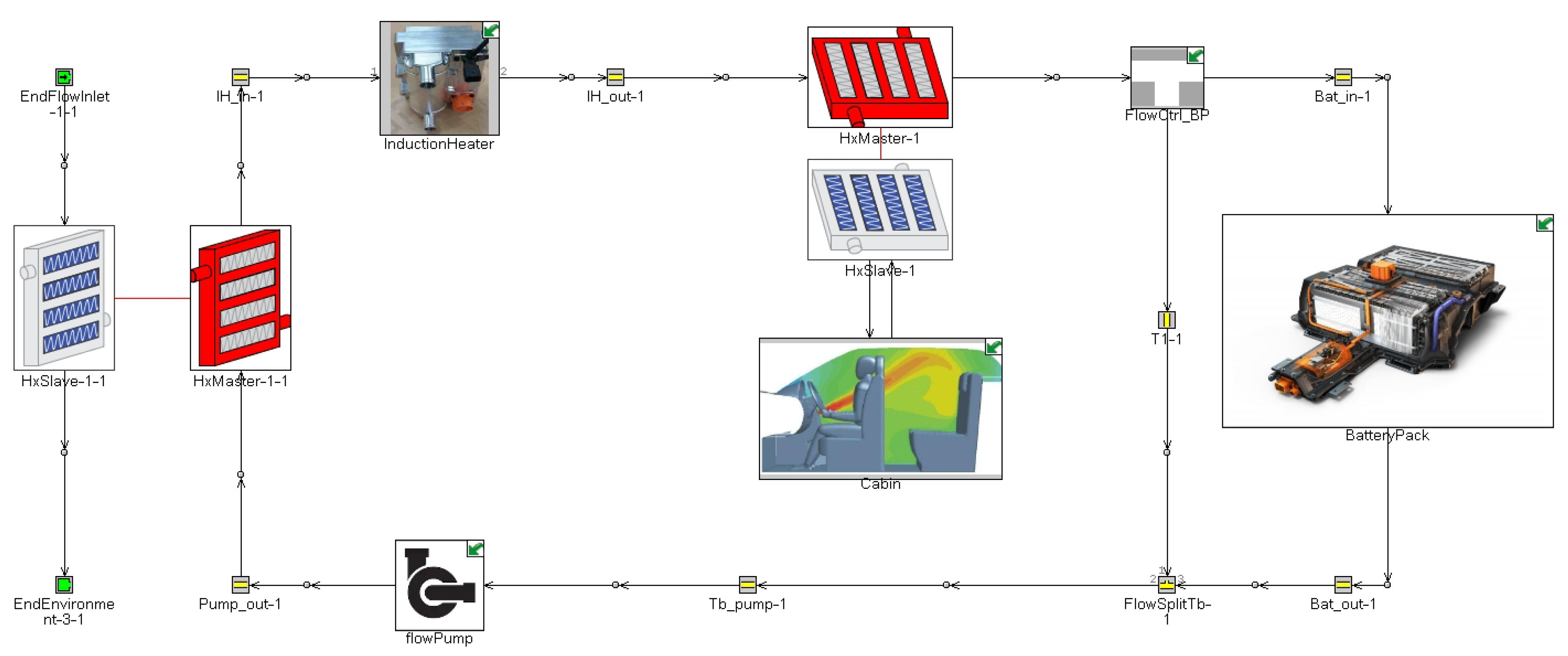
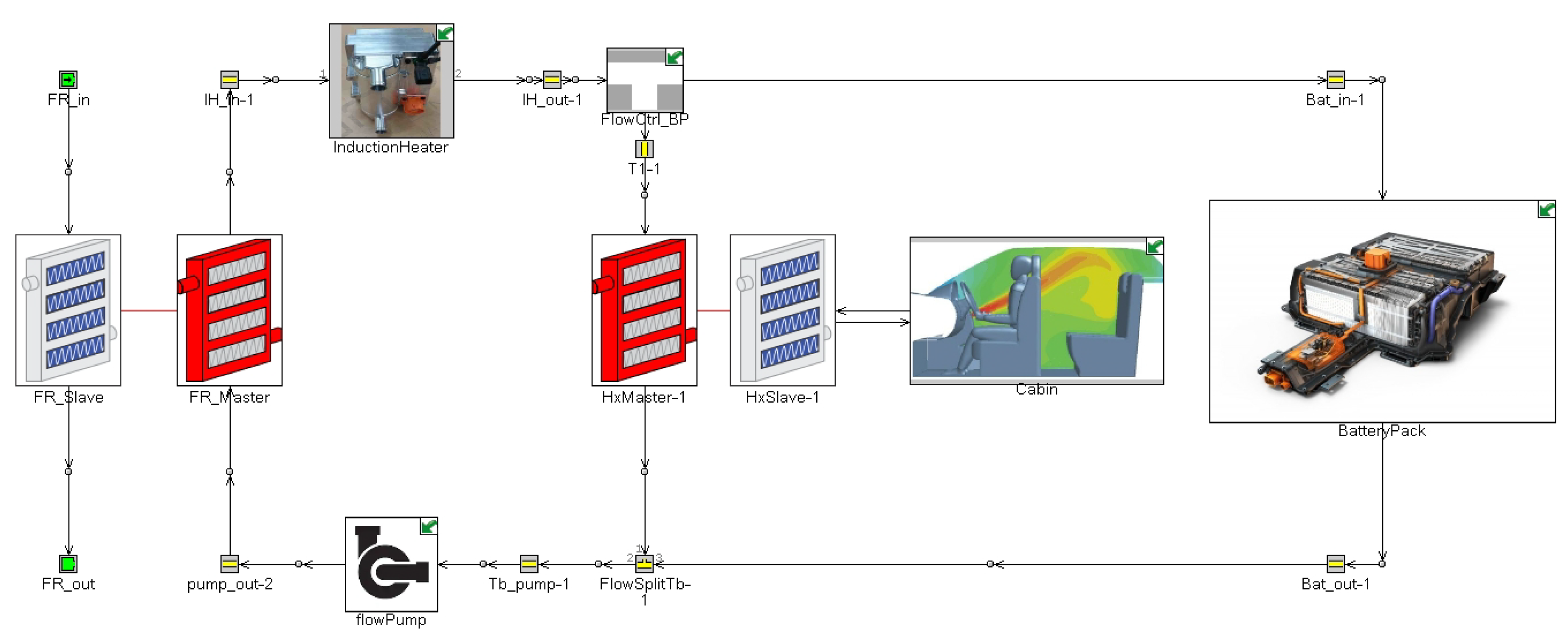
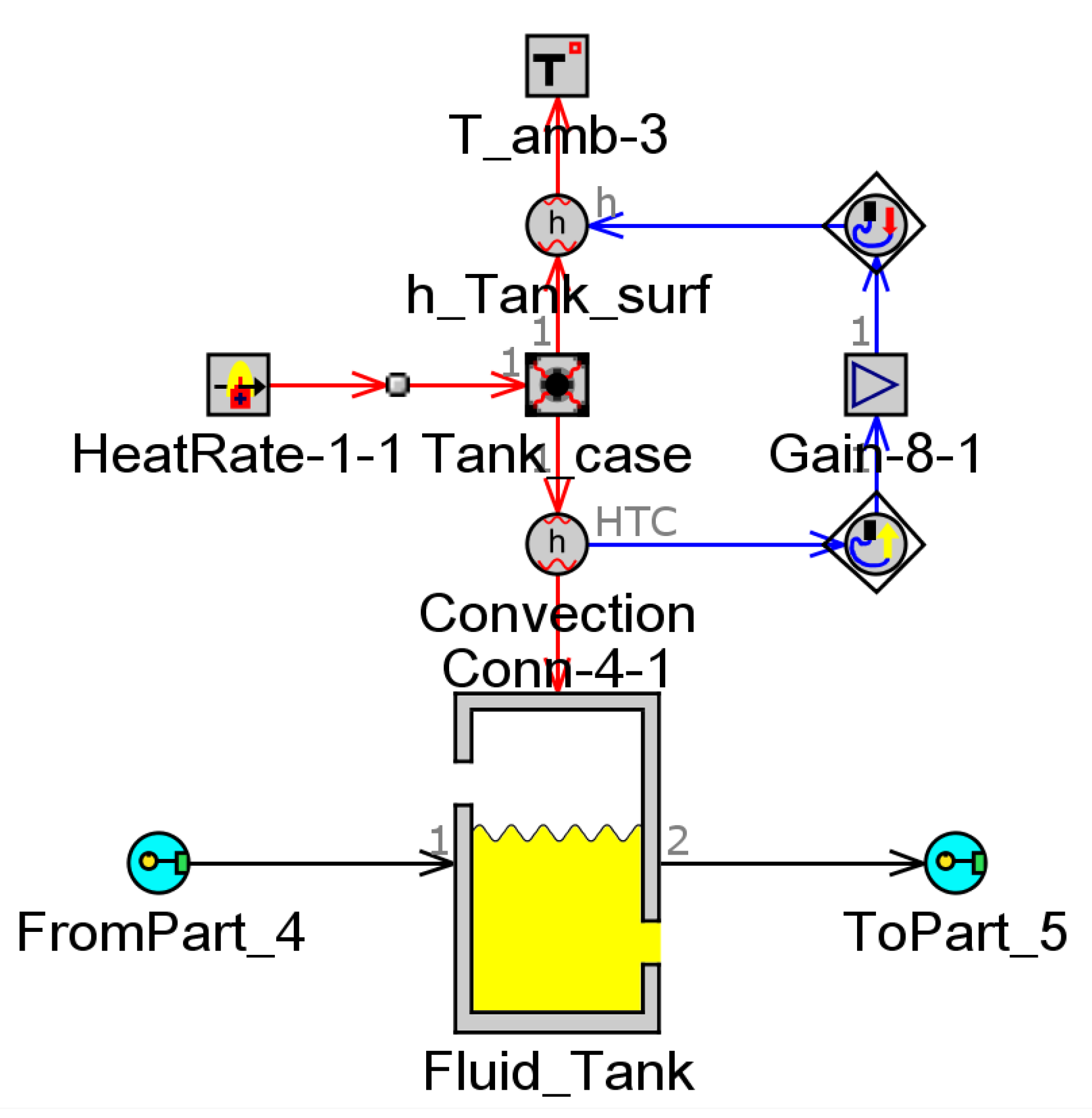
2. Modeling, Simulation, and System Description

Modeling, simulation, and system descriptions are covered in this section. GT-Suite (the industry-leading simulation tool with features and collections targeting at a variety of technologies of applications and industries) software was considered in this study. The working fluid transfers the heat inside pipes and flows separated to their surfaces, which is determined using a coefficient of heat transfer. The coefficient of heat transfer is considered at any point phase of the fluid velocity, thermo-physical characteristics, and the composition of the wall unevenness. The smooth pipes’ coefficient of heat transfer is determined using Equation (1). For a Reynolds number less than 2000, a Nusselt number of 3.6 is used; then, the heat transfer coefficient is defined by Equation (2).
h g = 1 2 C f ρ U eff C p Pr ( 2 3 )
h g = N u . k d
In the series system, where liquid follows the one predefined path, as shown in Figure 1. The induction heater is used to warm the liquid with the energy transferred from electric to heat until it gets into the heater core. Where heat is transferred to the passenger’s cabin, the air is blown over the coil to get a high temperature and circulate into the passenger’s cabin to deliver temperature higher than the outside temperature to drive safely. A three-way valve is used to direct the liquid. Then, the liquid is directed towards the flow channel surrounds the batteries from defined ways for the heat transfer. A flow pump is also used to pressurize the liquid “coolant” throughout the cycle.
In the parallel system, the liquid follows two predefined ways as opposed to the series system shown in Figure 2. The operating fluid follows two routes: one towards the battery pack and the other towards the heater core [50]. These are the two configurations extensively used in liquid heating or cooling systems in electric vehicles. In this study, the series configuration was utilized for battery thermal enhancement, i.e., to know the optimal solution or develop a thermal system for the battery. The details of the system components are described in the upcoming sections. The reason for choosing the liquid heating system is the heat transfer coefficient. The system using liquid has also been implemented in commercial EVs due to its high heating rate performance and compatibility. A liquid-based system can reduce energy consumption based on the performance feature of pressure drop, temperature drop, and homogeneity.

2.1. Induction Heater

One of the core elements of the battery thermal management system is an induction heater in the electric vehicle. The electric vehicle needs an independent heat-generating device since no engine holds the battery temperature and powers the heat pump. Due to the characteristics of rapid temperature rise by direct input of electric power, the most satisfactory solution for a heat source is an induction heater. The heater generates heat directly from a Litz coil by electromagnetic forces in work-pieces prepared from ferromagnetic materials, through which high-frequency AC voltage is produced. The induction heater has high-performance characteristics, and extraordinary rapid temperature increase times up to the optimal temperature [51]. The induction heater is also semi-permanent due to the lack of consumable parts [52]. Another critical aspect of the heater induction mechanism is that the heat is generated internally, instead of by heat conduction from an external heat source, and the battery heats up very quickly. Whenever the coil moves into contact with the work-piece, the induction heater coils are destroyed by heat. Hence, the nonmagnetic material-based bobbin is placed between the work-piece and the coil. Figure 3 shows a simulation diagram for an induction heater. By adding the power supply, the heater can conveniently produce enough heat without any safety concern.
The reason behind choosing the induction heater for liquid heating is the efficiency of an induction heater as compared to the resistance heater. The US Department of Energy has estimated electric coil efficiency as about 74–77% and induction at 84%. Moreover, induction heating prolongs the life of fixtures as the accurate heating provides rapid start-up to save time due to the absence of thermal inertia and makes the battery thermal system productive. Another factor involved in the selection is cost-effectiveness; a higher energy-saving rate is obtained if the power capacity is higher. Besides, heating by induction has a minimum loss of heat to the surroundings with direct transfer of energy to the liquid.
In contrast to the heat pump, an induction heater is sufficient in terms of energy-saving as thermal comfort, and battery thermal safety is an auxiliary load on the battery pack. Despite that, the heat pump system is more complex, and the upfront cost is more than the induction heater-based BTMS. Zhang et al. [53] found that the electric vehicle heat pump system reduced heating performance when working in cold weather conditions. Thus, full heat pump efficiency in cold weather cannot be reached.

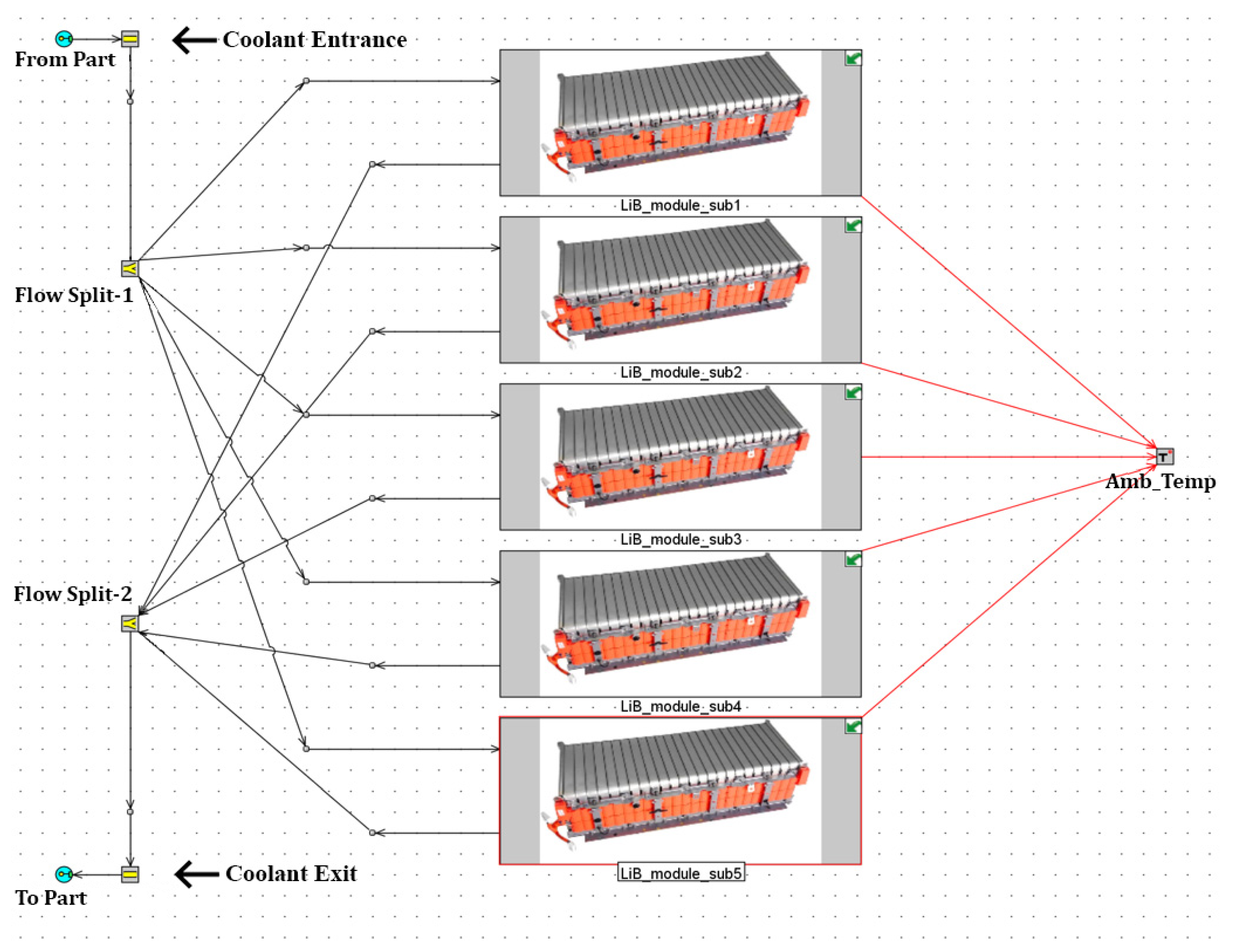
2.2. Lithium-ion Battery Pack

The battery is the heart and an integral component of the EVs. A pouch-type lithium polymer cell with a cathode NCM 622 (Nickel Cobalt Manganese Oxide) and graphite anode is considered as a reference battery cell to ensure an optimum temperature range and a consistent temperature delivery within the battery pack. The battery pack sits under the floor of the vehicle, and a full pack consists of five modules. The process of cell to battery pack assembly is illustrated in Figure 4. The battery cell size is 300 mm × 98 mm × 14 mm, and the capacity is 60 Ah. Li-ion polymer rechargeable batteries manufactured by LG-Electronics were used to model the battery pack; all other necessary technical information of a Li-ion battery is presented in Table 2.
The aim is to keep the battery operating at an appropriate temperature. Figure 5 shows the battery pack modeling diagram considered in this study. Three types of battery heating methods are used: convective heating, self-internal heating, and mutual pulse heating [42]. The convective heating approach can heat the battery both inside and outside. The fan creates a convective flow, and a heater transforms electric power to heat the fluid. Song [54] added a heating resistor into the forced air BTMS and heating batteries with convective. The author of Ref. [55] compared two types of battery heating strategies: silicon plate heating and forced air convection heating. Besides, a liquid heating system because of its high efficiency is commonly practiced in EV manufacturing.
Furthermore, the liquid flow channel needs to be constructed correctly. The system’s heat transfer capacity degrades, leaving the battery pack uneven in temperature distribution. In a liquid-based system with indirect-contact, the heat transfer fluid is conditioned using an induction heater and transported by a fixed heating circuit across the channels. Owing to the lower viscosity of the thermal fluid (ethylene glycol or water) than the dielectric fluids (e.g., mineral oil), the indirect form of liquid transmission is more practical to be implemented, resulting in a slightly higher fluid flow rate [56]. The thermophysical characteristics of the operating fluid are as follows: a specific heat capacity around 3323 J·kg−1·K−1, density of 1069 kg·m−3, kinematic viscosity of 2.58 × 10⁻⁶, and thermal conductivity of 0.3892 W·m−1·K−1.
The working fluid has an indirect connection with the battery and warms the liquid “coolant” just before it enters into the pack. The working fluid circulated through the flow channel between the batteries and transferred the heat to the batteries inside the battery pack. The flow channel surrounding the battery was tightly arranged of pipes and covered the pack from all directions. The dimensions of the flow pattern are as follows: pipe diameter of around 10.6 mm, overall width from the entrance of the operating fluid to the outlet of about 5000 mm, and the gap between two consecutive pipes of almost 10 mm. The working fluid needs to be powered by the applicable device. A pump is installed along with the liquid circulation. The lowest and highest flow rates were 3 and 27 LPM, respectively. Meanwhile, the increasing flow rate of cooling liquid caused the energy consumption of the pump to increase dramatically because the pack itself mainly supplies the battery energy consumption for the heating system.

2.3. Cabin

Air conditioning is one of the leading automobile systems used to preserve the inside comfort, including temperature, humidity, and air velocity. In the case of an electric vehicle, there is no engine to drive this kind of system. The same working fluid used for battery heating is used in a heater core to provide hot air inside the cabin for the passenger’s comfort. A prominent factor in driving protection is also how thermally stable the cabin situation is for the driver [57]. In one study, car drivers missed 50% of test signals at 27 °C, the reaction time being 22% lower than at 21 °C due to thermal discomfort [58]. Therefore, thermal comfort is essential to provide heating in cold weather and cooling in hot and humid weather. In this analysis, heating was supplied by the air blow over the heater core at low ambient temperatures. A fan was used for air circulation. The design properties of the cabin are given in Table 3.
Another critical component of BTMS is the heater core. The heater core was considered inside the cabin to offer heat. The heater core conditions were an airflow rate of 200–400 CMH; working fluid flow rates of 3, 6, and 10 LPM; and supply water temperature of 85 °C. The heater core simulation diagram is demonstrated in Figure 6, while experimental and simulation data are shown in Figure 7, where air volume and flow rate data are plotted with the heater capacity.

2.4. Experimental Conditions

The heat transfer rate related to the flow rate of working fluid for the BTMS of an electric vehicle was investigated under cold climate situations based on the existing standard with heater power variations of 2, 4, and 6 kW and outside temperatures of −20, −10, and 0 °C. Table 4 and Table 5 display the experimental conditions for the cabin and battery pack.

3. Results and Discussion

In this section, the battery thermal management system for the cabin and battery of an electric vehicle is examined with flow rate and induction heater powers under cold weather conditions. The flow rate and the capacity of the induction heater were varied as 3, 5, 7, 10, 20, and 27 LPM and 2, 4, and 6 kW, respectively. Additionally, system’s outside temperatures were 0, −10, and −20 °C.

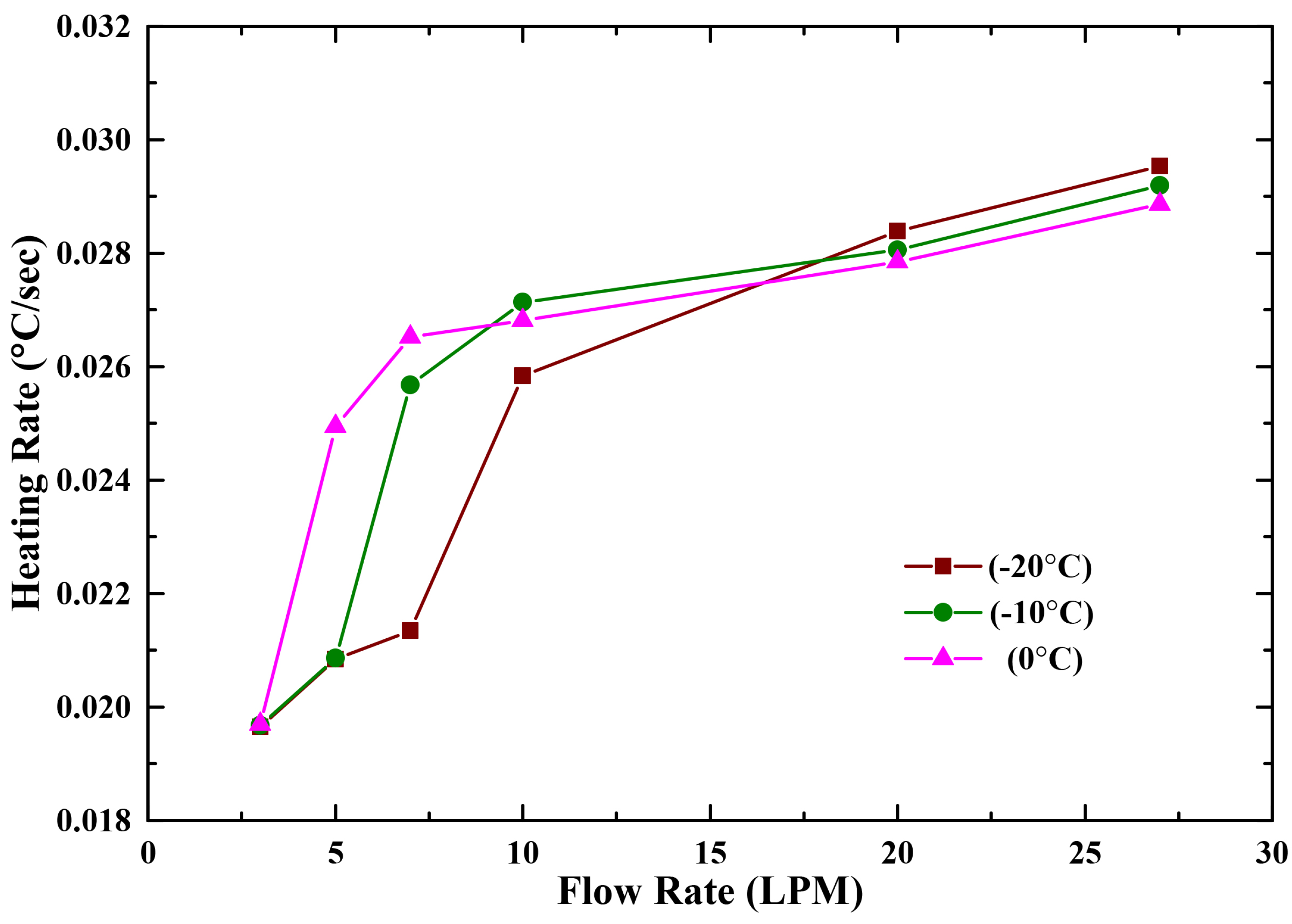
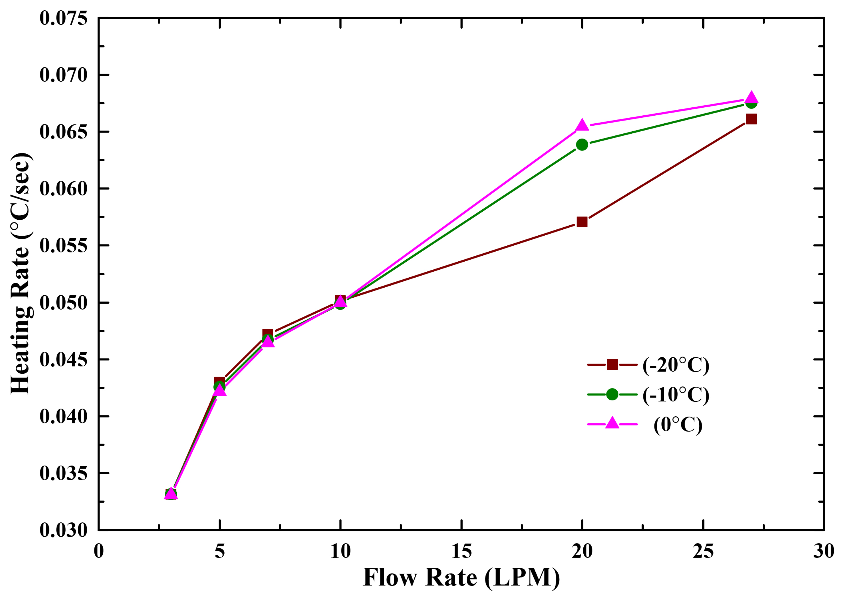
3.1. Battery Heat Transfer Rate

Figure 8 illustrates the differences in the heat transfer rate vs. the flow rate of working fluid under the cold weather temperatures of 0, −10, and −20 °C with 2 kW heater capacity, respectively, for the battery. As shown in Figure 8, there is a smooth increment in the pattern; the battery heating system has an improved heating rate with an increase in the working fluid flow rate. One can see that the heating rate at 10 LPM is around 0.0271 °C/s, while, at 27 LPM, it is 0.0291 °C/s at ambient temperature −10 °C, which demonstrates the rise in the heating rate with the LPM. Owing to the high specific ability, the heat transfer rate of liquid fluid is higher. In addition, the induction heater capacity affects the increase in the heating rate.
Figure 9 corresponds to the heating rate impact on the flow rate of working fluid with the battery heating power of 4 kW under cold weather temperatures 0, −10, and −20 °C, respectively. It depicts that the heating rate of the battery heating system increases towards the optimum flow rate; the heating rate is about 0.0366 °C/s with 5 LPM. On the other hand, it is 0.0500 °C/s with a flow rate of 20 LPM and peaked at 0.0507 °C/s with 27 LPM at an outside temperature of 0 °C. The induction heater capacity also increased from 2 to 4 kW in this case, which has a positive impact on the improvement of the heating rate. The figure shows the increase in the heating rate with the change in the rate of working fluid flow.
Figure 10 demonstrates the heating rate regarding the flow rate with 6 kW heater capacity at cold weather temperatures of 0, −10, and −20 °C, respectively, for the battery. The heating rate of all three ambient temperature conditions begins to rise over the same rate up to 10 LPM. After that, unusual changes in the pattern can be seen. The heating rate is approximately the same, with a minor difference at the flow rate of 27 LPM. The battery heating rate is also improved as the flow rate increases. The heating rate with 3 LPM is almost 0.0331 °C/s, and, with 27 LPM, it is 0.0661 °C/s, which is the maximum heat transfer rate at −20 °C outside temperature. In this condition, the induction heater capacity is the maximum of all the times, which also affected the rate of heat transfer.

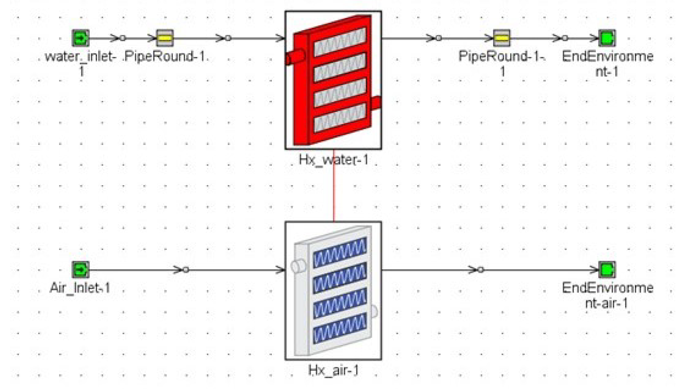
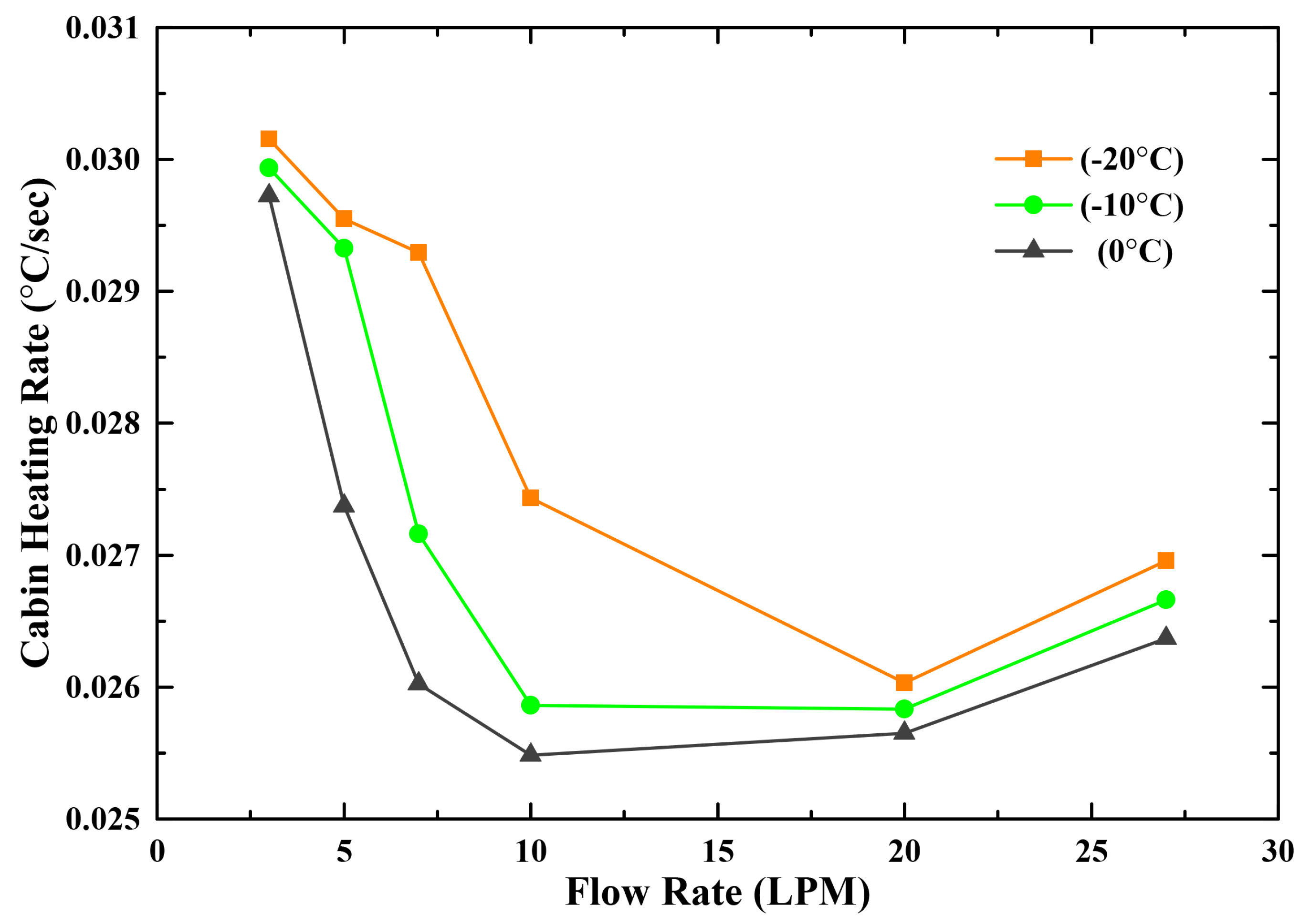
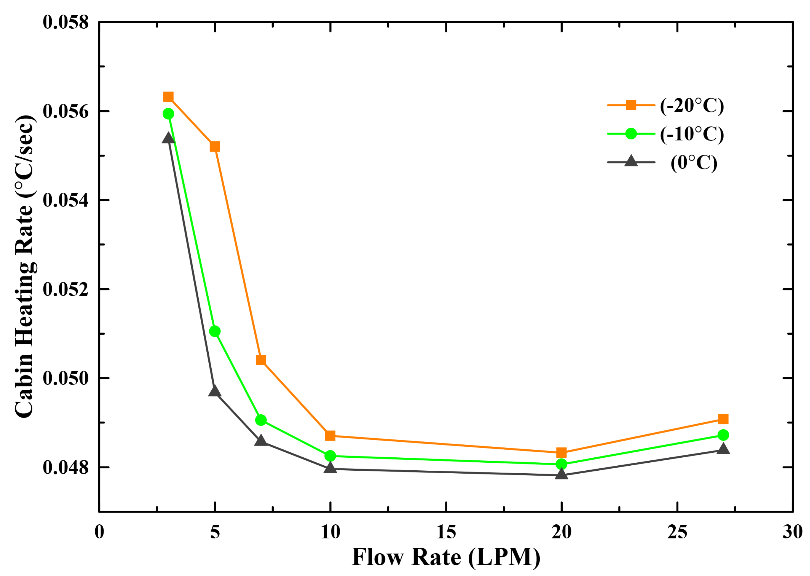
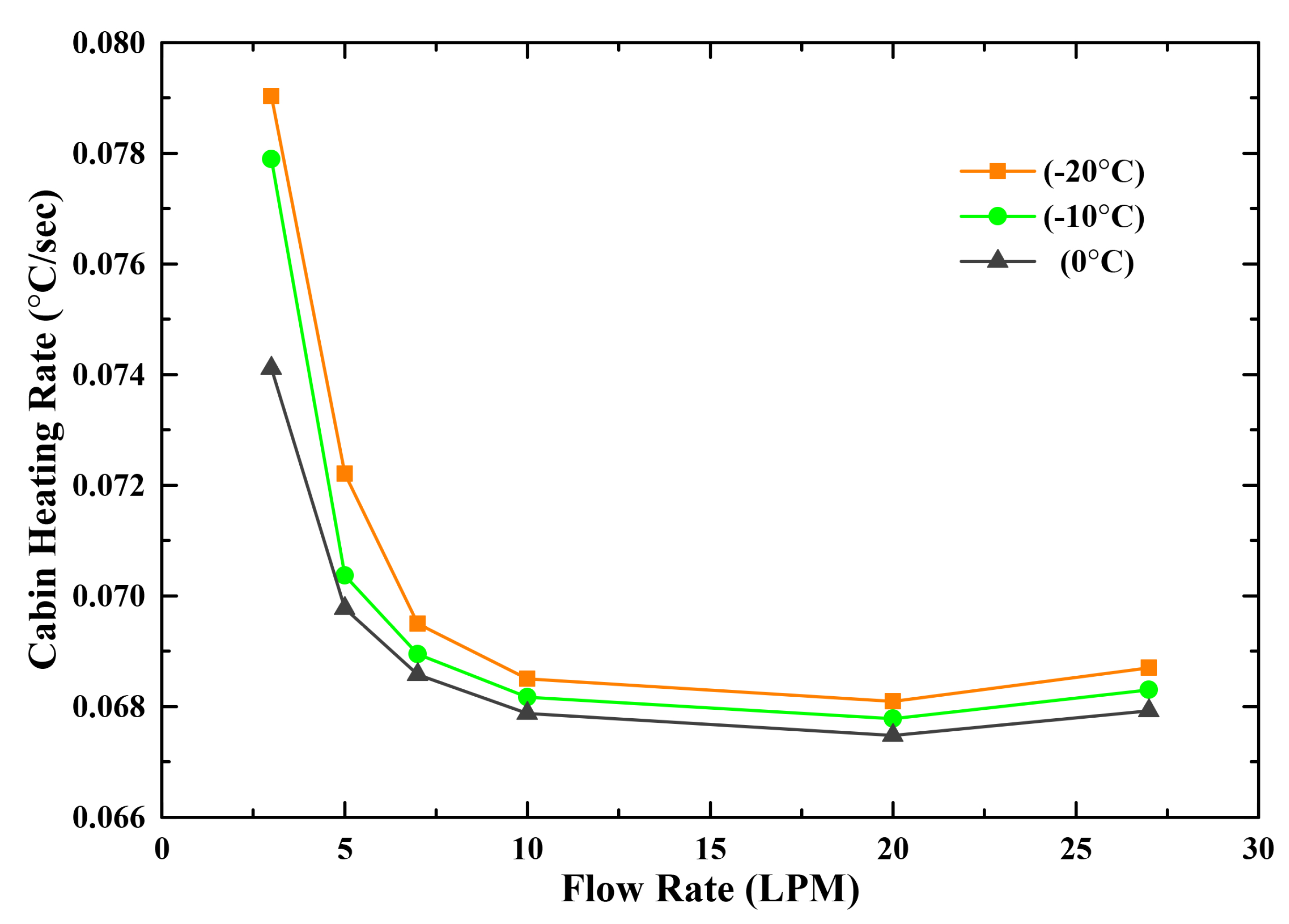
3.2. Cabin Heat Transfer Rate

The air condition system is essential to guarantee thermal comfort for drivers and passengers. Automobiles use the engine exhaust’s gas waste heat for cabin heating with internal combustion engines. Despite that, EV needs separate equipment for heating since there is no exhaust gas for heating. The heater core employed heat for the cabin with the help of an induction heater. The hot air was blown into the cabin for heating. The effects of the cabin heat transfer rate are discussed in this part of the section experiment findings. The ambient temperatures considered for the experiments were 0, −10, and −20 °C. The induction heater capacity was 2, 4, and 6 kW. The airflow considered for cabin heating was about 400 CMH.
Figure 11 presents the influence of the cabin heating rate in terms of the flow rate of the working fluid. Cabin heating is keen for safe driving and passenger comfort. The cabin heating rate is determined to check the performance of the system. Variations of the heating rate for flow rate under three different outside temperatures are illustrated. The airflow and the heater capacity considered for the experiment were 400 CMH and 2 kW, respectively. It can be observed that the heating rate is the maximum at 3 LPM, which is 0.0301 °C/s at an outside temperature of −20 °C. All variations of ambient temperatures represent the increase in the flow direction, causing the reduction in the heating rate up to 10 LPM; after that, there is an irregular pattern followed by 20 LPM. Once LPM hit all three variations at 20, it again depicts the increase in the heating rate that shows the flow rate effect on heat transfer.
Figure 12 demonstrates the effects of the cabin heating rate versus the flow rate of a working fluid. The cabin heating rate is investigated to find the thermal performance of the system. The airflow and the heater capacity considered for the experiment were 400 CMH and 4 kW, respectively. Variations of the heating rate under three different ambient temperatures to flow rate are illustrated in Figure 12. It can be observed that the heating rate is highest at −20 °C ambient temperature with a flow rate of 3 LPM, which is 0.0563 °C/s. All three variations of ambient temperatures show that the change in flow direction triggers a decrease in the heating rate followed by 20 LPM after the rise in heating rate level from 20 to 27 LPM, which indicates the effect of the change in flow rate.
The cabin heating rate is measured to assess the performance. Figure 13 illustrates the effect of the cabin heating rate on the working fluid flow rate. The airflow and heater capacity considered for the experiment were 400 CMH and 6 kW, respectively. Variations of the heating rate concerning flow rate under various outside temperatures are shown in Figure 13. All three changes in ambient temperatures show that the change in flow direction reasons for the heating rate to decrease up to 20 LPM. When LPM reached all three variations at 20, the rise in the heating rate, which directs the influence of flow rate rise again, is at the highest heating level at a flow rate of 3 LPM, which is 0.0790 °C/s at an outside temperature of −20 °C. In contrast, the minimum is approximately 0.06748 °C/s with the 20 LPM flow rate at 0 °C ambient temperature.
Figure 14 demonstrates the influence of power consumption on the working fluid flow rate. The consumption of pump power is critical for measuring the overall efficiency of the system. It can be seen that there is a linear increase in power consumption and minimum power consumption for the pump is about 32.5 W with 3 LPM and nearly 43 W with 27 LPM. The values show that the change in fluid flow rate is responsible for the increase in power consumption. To find the systems optimum flow rate considering ambient temperature for each heater capacity and power consumption, Equation (3) is used, where m ˙ represents the mass flow rate.
m ˙ = 5 0.15 ( b a t t e r y t e m p ) + 0.005 ( b a t t e r y t e m p ) 2

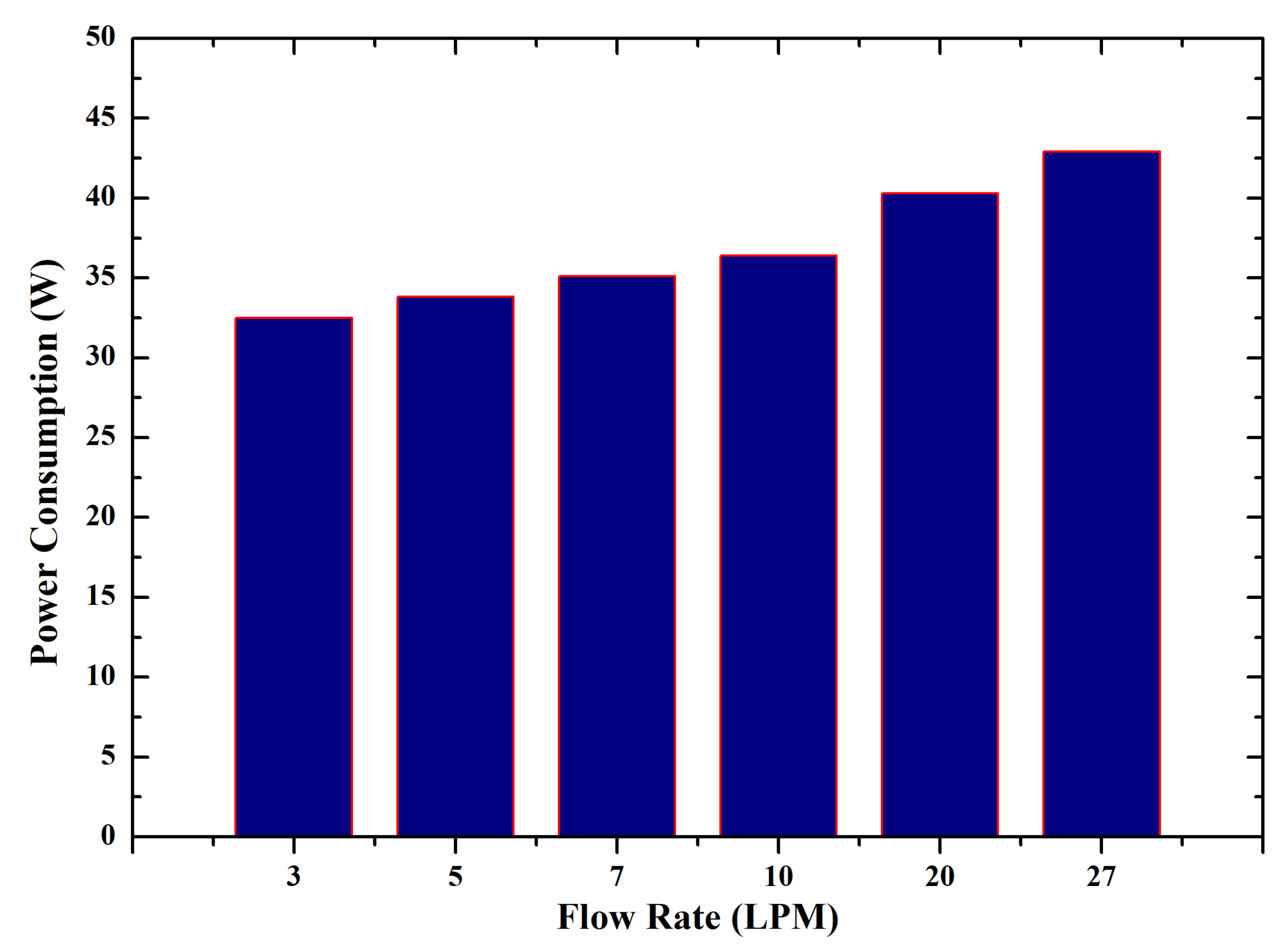
3.3. Overall System Efficiency

Battery and cabin heat transfer rate are discussed above. In this section, we discuss the overall efficiency of an electric vehicle’s battery and cabin heating system, including power consumption by the system during the operating cycle. Power consumption is also shown in Figure 14. The power consumption separates the heating rate of the battery and cabin in order to evaluate the systems’ effectiveness and performance as a function of flow rate.
Firstly, Figure 15 presents the overall efficiency of the thermal management system in a series configuration to flow rate. The variations of three different ambient temperatures and the capacity of the induction heater considered for this experiment was 2 kW. All variations in the ambient temperatures display the irregular pattern of increments and decrements. The data indicate that the efficiency with the low LPM is higher and is lower with the maximum flow rate due to the increase in the usage of the pump power consumption as flow rate increases also the pump power consumption, which causes the overall efficiency to decrease. It can be seen that efficiency is at a peak at an outside temperature of 0 °C with a flow rate of 7 LPM flow rate, which is almost 0.00075 °C/s/W.
On the other hand, Figure 16 describes the efficiency of the battery thermal management system in a series configuration versus flow rate. Variations of three different ambient temperatures are shown. The 4 kW capacity of the induction heater was considered for this experiment. All ambient temperature fluctuations Show an irregular pattern, including an increase and decrease up to 20 LPM; after that, output decrease, followed by 27 LPM at the same pace. However, the efficiency is maximum at 0 °C ambient temperature due to less power consumption than other ambient temperatures. It can be depicted that with a flow rate 3 LPM at an outside temperature of −10 °C, the efficiency is lowest, and, with a flow rate 27 LPM, the efficiency on all three outside temperatures is nearly the same.
Finally, Figure 17 refers to the efficiency in terms of flow rate for the battery thermal management system. Variations of three different ambient temperatures are shown. The 6 kW capacity of the induction heater was considered for this experiment. All variations in the ambient temperature show a gradual trend with the same pace up to 10 LPM, and an increase in efficiency up to 20 LPM. In the case of 0 and −10 °C outside temperatures, efficiency decreases after 20 LPM, while the trend in heating rate efficiency with flow rate at an outside temperature of −20 °C is opposite to the trends at −10 and 0 °C. One can see that there is a significant efficiency increase from 10 to 20 LPM; efficiency is maximum at 0 °C ambient temperature due to lower power consumption relative to other ambient temperatures. It reveals that, with a flow rate of 3 LPM at ambient temperature 0 °C, the efficiency is lowest, while, with a flow rate of 20 LPM at the same outside temperature, it is the maximum.

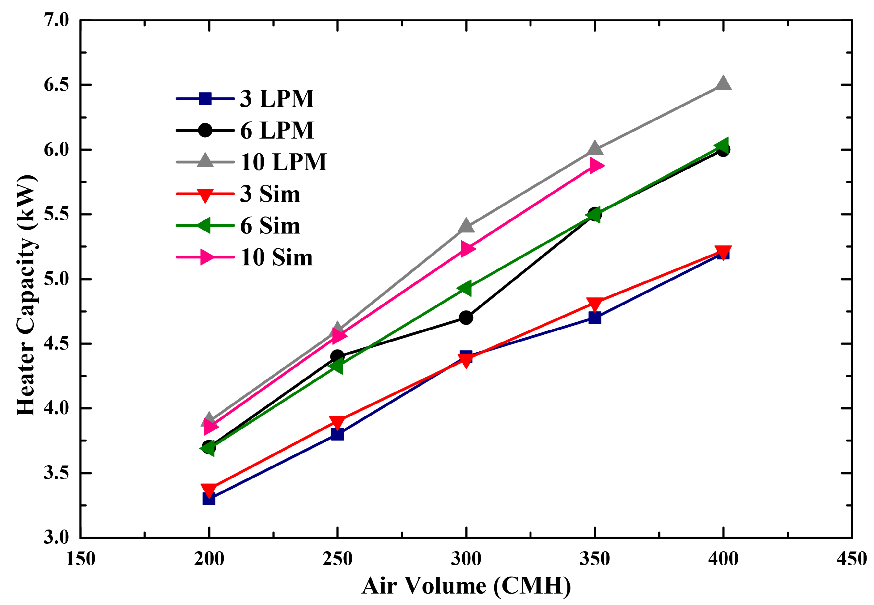
3.4. Comparison of Simulation and Experimental Results

To evaluate the validity of the simulation results with experimental data, a battery pack was tested on a vehicle to match the preciseness of the proposed system, and the findings are demonstrated in Figure 18. The flow rate of 10 LPM, heater power of 2 kW, and the ambient temperatures of −20, −10, and 0 °C, respectively, were considered as test conditions. The results indicate that the heat transfer coefficient for experimental and simulation analysis was 0.026882 and 0.026816 °C/s, respectively. The outcomes are almost the same and demonstrate the similarity of the proposed model.

4. Conclusions

At low temperatures, the lithium-ion battery faces reduced power efficiency and deterioration. Poor performance at low temperatures would hamper the deployment of EVs significantly. Therefore, preheating the ambient temperature to normal range and optimizing the efficiency of the lithium-ion batteries is essential in the cold climate for an EVs battery thermal management system (BTMS). A BTMS by using an induction heater with a single-phase indirect liquid heating system is proposed in this paper. To evaluate the proposed system efficiency, various operating parameters are used to consider how battery pack thermal performance can be achieved in the optimal operating temperature range.
The research investigated the systems heating efficiency under various cold weather conditions by using heating powers of 2, 4, and 6 kW. The performance of the system slightly improves with the rise in flow rate and heating power. The heat transfer rate was maximum with 6 kW heater capacity at 27 LPM, which indicates the boost in heating rate and the influence of induction heater capacity throughout. On the one hand, to consider the optimal conditions with each capacity of an induction heater under subzero temperature, an equation is used. The heater and pump power consumption are also considered for the determination of optimal flow rate conditions. The optimal flow rate with 2 kW of heater capacity at 0 °C is 7 LPM, with 4 kW at −10 °C is 10 LPM, and finally with 6 kW at −20 °C is 27 LPM; to develop the battery heating system, it is vital to know that.
The BTMS provides an appropriate operating temperature for battery packs and thus ensures high usage performance and long cycle life. Furthermore, to prevent leakage, a liquid heating system requires careful seal design and operation. Besides, using an induction heater, and by adjusting the working fluid flow rate, the reliability, safety, and performance of the electric vehicle may be improved. From a manufacturing viewpoint, a 64-kWh capacity battery pack coupled with 6 kW of heating power and a flow rate of 27 LPM at outside temperature conditions of 0, −10, and −20 °C is recommended. The proposed BTMS could be a practical approach and help design or analyze the various battery electric vehicle thermal management systems in the future.

Author Contributions

Conceptualization, G.S.K., and Y.C.P.; methodology, G.S.K., and W.R.; Software, W.R., G.S.K., and Y.C.P.; Validation, W.R., G.S.K., and Y.C.P.; formal analysis, W.R., and G.S.K.; investigation, G.S.K.; resources, Y.C.P.; data curation G.S.K. and W.R.; Writing—original draft preparation, W.R.; writing—review and editing, W.R., and G.S.K.; Supervision, Y.C.P.; funding acquisition, Y.C.P.; and project administration, Y.C.P. All authors have read and agreed to the published version of the manuscript.

Funding

The technology innovation program supported this work (No. 20182020109700, development of a hybrid cooling system for refrigeration truck with an ejector) funded by the Ministry of Trade, Industry and Energy (MOTIE, Korea) and by the National Research Foundation of Korea (No. 2020R1A2C1011871).

Conflicts of Interest

There is no conflict of interest between the authors.

Abbreviations

AAmpere
AhAmpere hour
BEVBattery electric vehicle
BTMSBattery thermal management system
CfFanning friction factor of smooth pipe
CpSpecific heat
ddiameter
EVElectric vehicle
hgHeat transfer coefficient
kThermal conductivity
kWKilowatt
Li-BLithium-ion battery
Li-ionLithium-ion
LPMLiter per minute
m ˙ Mass flow rate
NuNusselt number
PCMPhase change material
PrPrandtl number
UeffEffective velocity outside boundary layer
ρ Density

References

  1. BP. BP Energy Outlook 2019 Edition. 2019. Available online: https://www.bp.com/content/dam/bp/business-sites/en/global/corporate/pdfs/energy-economics/energy-outlook/bp-energy-outlook-2019.pdf (accessed on 21 September 2020).
  2. Worwood, D.; Kellner, Q.; Wojtala, M.; Widanage, W.; McGlen, R.; Greenwood, D.; Marco, J. A new approach to the internal thermal management of cylindrical battery cells for automotive applications. J. Power Sources 2017, 346, 151–166. [Google Scholar] [CrossRef]
  3. Khan, P.W.; Byun, Y.C. Smart Contract Centric Inference Engine For Intelligent Electric Vehicle Transportation System. Sensors 2020, 20, 4252. [Google Scholar] [CrossRef] [PubMed]
  4. Budde-Meiwes, H.; Drillkens, J.; Lunz, B.; Muennix, J.; Rothgang, S.; Kowal, J.; Sauer, D.U. A review of current automotive battery technology and future prospects. Proc. Inst. Mech. Eng. Part D J. Automob. Eng. 2013, 227, 761–776. [Google Scholar] [CrossRef]
  5. Gandoman, F.H.; Jaguemont, J.; Goutam, S.; Gopalakrishnan, R.; Firouz, Y.; Kalogiannis, T.; Omar, N.; Mierlo, J.V. Concept of reliability and safety assessment of lithium-ion batteries in electric vehicles: Basics, progress, and challenges. Appl. Energy 2019, 251, 113343. [Google Scholar] [CrossRef]
  6. Mohammed, A.H.; Esmaeeli, R.; Aliniagerdroudbari, H.; Alhadri, M.; Hashemi, S.R.; Nadkarni, G.; Farhad, S. Dual-purpose cooling plate for thermal management of prismatic lithium-ion batteries during normal operation and thermal runaway. Appl. Therm. Eng. 2019, 160, 114106. [Google Scholar] [CrossRef]
  7. Lu, L.; Han, X.; Li, J.; Hua, J.; Ouyang, M. A review on the key issues for lithium-ion battery management in electric vehicles. J. Power Sources 2013, 226, 272–288. [Google Scholar] [CrossRef]
  8. Zhao, R.; Zhang, S.; Liu, J.; Gu, J. A review of thermal performance improving methods of lithium ion battery: Electrode modification and thermal management system. J. Power Sources 2015, 299, 557–577. [Google Scholar] [CrossRef]
  9. Bandhauer, T.M.; Garimella, S.; Fuller, T.F. A Critical Review of Thermal Issues in Lithium-Ion Batteries. J. Electrochem. Soc. 2011, 158, R1. [Google Scholar] [CrossRef]
  10. Wang, Q.; Jiang, B.; Xue, Q.; Sun, H.; Li, B.; Zou, H.; Yan, Y. Experimental investigation on EV battery cooling and heating by heat pipes. Appl. Therm. Eng. 2015, 88, 54–60. [Google Scholar] [CrossRef]
  11. Pesaran, A.; Keyser, M.; Kim, G.; Santhanagopalan, S.; Smith, K. Tools for Designing Thermal Management of Batteries in Electric Drive Vehicles (Presentation); Technical Report; National Renewable Energy Lab. (NREL): Golden, CO, USA, 2013. [Google Scholar]
  12. Saw, L.H.; Yew, M.C.; Yew, M.K.; Chong, W.T. Numerical analyses on aluminum foams cooling plate for lithium-ion batteries. Energy Procedia 2017, 105, 4751–4756. [Google Scholar] [CrossRef]
  13. Zhang, S.; Xu, K.; Jow, T. The low temperature performance of Li-ion batteries. J. Power Sources 2003, 115, 137–140. [Google Scholar] [CrossRef]
  14. Lei, Z.; Zhang, Y.; Lei, X. Improving temperature uniformity of a lithium-ion battery by intermittent heating method in cold climate. Int. J. Heat Mass Transf. 2018, 121, 275–281. [Google Scholar] [CrossRef]
  15. Ladrech, F. Battery thermal management for HEV & EV–Technology overview. In Proceedings of the Automotive Summit, Brussels, Belgium, 10 November 2010. [Google Scholar]
  16. Pesaran, A.A. Battery thermal models for hybrid vehicle simulations. J. Power Sources 2002, 110, 377–382. [Google Scholar] [CrossRef]
  17. Sato, N. Thermal behavior analysis of lithium-ion batteries for electric and hybrid vehicles. J. Power Sources 2001, 99, 70–77. [Google Scholar] [CrossRef]
  18. Liao, Z.; Zhang, S.; Li, K.; Zhang, G.; Habetler, T.G. A survey of methods for monitoring and detecting thermal runaway of lithium-ion batteries. J. Power Sources 2019, 436, 226879. [Google Scholar] [CrossRef]
  19. Motloch, C.G.; Christophersen, J.P.; Belt, J.R.; Wright, R.B.; Hunt, G.L.; Sutula, R.A.; Duong, T.; Tartamella, T.J.; Haskins, H.J.; Miller, T.J. High-Power Battery Testing Procedures and Analytical Methodologies for HEVs; SAE Technical Paper Series; SAE International: Warrendale, PA, USA, 2002. [Google Scholar] [CrossRef]
  20. Ramadass, P.; Haran, B.; White, R.; Popov, B.N. Capacity fade of Sony 18,650 cells cycled at elevated temperatures. J. Power Sources 2002, 112, 614–620. [Google Scholar] [CrossRef] [Green Version]
  21. Burow, D.; Sergeeva, K.; Calles, S.; Schorb, K.; Börger, A.; Roth, C.; Heitjans, P. Inhomogeneous degradation of graphite anodes in automotive lithium ion batteries under low-temperature pulse cycling conditions. J. Power Sources 2016, 307, 806–814. [Google Scholar] [CrossRef]
  22. Jaguemont, J.; Boulon, L.; Dube, Y. Characterization and Modeling of a Hybrid-Electric-Vehicle Lithium-Ion Battery Pack at Low Temperatures. IEEE Trans. Veh. Technol. 2016, 65, 1–14. [Google Scholar] [CrossRef] [Green Version]
  23. Jaguemont, J.; Boulon, L.; Venet, P.; Dube, Y.; Sari, A. Low temperature aging tests for lithium-ion batteries. In Proceedings of the 2015 IEEE 24th International Symposium on Industrial Electronics (ISIE), Buzios, Brazil, 3–5 June 2015. [Google Scholar] [CrossRef]
  24. Friesen, A.; Horsthemke, F.; Mönnighoff, X.; Brunklaus, G.; Krafft, R.; Börner, M.; Risthaus, T.; Winter, M.; Schappacher, F.M. Impact of cycling at low temperatures on the safety behavior of 18,650-type lithium ion cells: Combined study of mechanical and thermal abuse testing accompanied by post-mortem analysis. J. Power Sources 2016, 334, 1–11. [Google Scholar] [CrossRef]
  25. Smart, M.; Ratnakumar, B.; Whitcanack, L.; Chin, K.; Surampudi, S.; Croft, H.; Tice, D.; Staniewicz, R. Improved low-temperature performance of lithium-ion cells with quaternary carbonate-based electrolytes. J. Power Sources 2003, 119–121, 349–358. [Google Scholar] [CrossRef]
  26. Gao, F.; Tang, Z. Kinetic behavior of LiFePO4/C cathode material for lithium-ion batteries. Electrochim. Acta 2008, 53, 5071–5075. [Google Scholar] [CrossRef]
  27. Jung, J.; Jeon, Y.; Lee, H.; Kim, Y. Numerical study of the effects of injection-port design on the heating performance of an R134a heat pump with vapor injection used in electric vehicles. Appl. Therm. Eng. 2017, 127, 800–811. [Google Scholar] [CrossRef]
  28. Lin, H.P.; Chua, D.; Salomon, M.; Shiao, H.; Hendrickson, M.; Plichta, E.; Slane, S. Low-temperature behavior of Li-ion cells. Electrochem. Solid State Lett. 2001, 4, A71. [Google Scholar] [CrossRef]
  29. Nagasubramanian, G. Electrical characteristics of 18650 Li-ion cells at low temperatures. J. Appl. Electrochem. 2001, 31, 99–104. [Google Scholar] [CrossRef]
  30. Gogoana, R. Internal Resistance Variances in Lithium-ion Batteries and Implications in Manufacturing. Ph.D. Thesis, Massachusetts Institute of Technology, Cambridge, MA, USA, 2012. [Google Scholar]
  31. Ouyang, M.; Chu, Z.; Lu, L.; Li, J.; Han, X.; Feng, X.; Liu, G. Low temperature aging mechanism identification and lithium deposition in a large format lithium iron phosphate battery for different charge profiles. J. Power Sources 2015, 286, 309–320. [Google Scholar] [CrossRef]
  32. Kim, J.; Oh, J.; Lee, H. Review on battery thermal management system for electric vehicles. Appl. Therm. Eng. 2019, 149, 192–212. [Google Scholar] [CrossRef]
  33. Chen, Y.; Evans, J.W. Heat transfer phenomena in lithium/polymer-electrolyte batteries for electric vehicle application. J. Electrochem. Soc. 1993, 140, 1833. [Google Scholar] [CrossRef]
  34. Pesaran, A.A. Battery thermal management in EV and HEVs: Issues and solutions. Battery Man 2001, 43, 34–49. [Google Scholar]
  35. Khan, M.; Swierczynski, M.; Kær, S. Towards an Ultimate Battery Thermal Management System: A Review. Batteries 2017, 3, 9. [Google Scholar] [CrossRef] [Green Version]
  36. Effat, M.B.; Wu, C.; Ciucci, F. Modeling efforts in the key areas of thermal management and safety of lithium ion battery cells: A mini review. Asia-Pac. J. Chem. Eng. 2016, 11, 399–406. [Google Scholar] [CrossRef]
  37. Saw, L.H.; Ye, Y.; Tay, A.A. Integration issues of lithium-ion battery into electric vehicles battery pack. J. Clean. Prod. 2016, 113, 1032–1045. [Google Scholar] [CrossRef]
  38. Rao, Z.; Wang, S. A review of power battery thermal energy management. Renew. Sustain. Energy Rev. 2011, 15, 4554–4571. [Google Scholar] [CrossRef]
  39. Huo, Y.; Rao, Z. Investigation of phase change material based battery thermal management at cold temperature using lattice Boltzmann method. Energy Convers. Manag. 2017, 133, 204–215. [Google Scholar] [CrossRef]
  40. Zhang, C.; Jin, X.; Li, J. PTC self-heating experiments and thermal modeling of lithium-ion battery pack in electric vehicles. Energies 2017, 10, 572. [Google Scholar] [CrossRef] [Green Version]
  41. Wu, W.; Wang, S.; Wu, W.; Chen, K.; Hong, S.; Lai, Y. A critical review of battery thermal performance and liquid based battery thermal management. Energy Convers. Manag. 2019, 182, 262–281. [Google Scholar] [CrossRef]
  42. Ji, Y.; Wang, C.Y. Heating strategies for Li-ion batteries operated from subzero temperatures. Electrochim. Acta 2013, 107, 664–674. [Google Scholar] [CrossRef]
  43. Luo, Y.; Lang, C.; Luo, B. Investigation into heating system of lithium-ion battery pack in low-temperature environment. J. South China Univ. Technol. (Nat. Sci.) 2016, 44, 100–106. [Google Scholar]
  44. Zhang, J.; Ge, H.; Li, Z.; Ding, Z. Internal heating of lithium-ion batteries using alternating current based on the heat generation model in frequency domain. J. Power Sources 2015, 273, 1030–1037. [Google Scholar] [CrossRef]
  45. Zhu, T.; Min, H.; Yu, Y.; Zhao, Z.; Xu, T.; Chen, Y.; Li, X.; Zhang, C. An Optimized Energy Management Strategy for Preheating Vehicle-Mounted Li-ion Batteries at Subzero Temperatures. Energies 2017, 10, 243. [Google Scholar] [CrossRef] [Green Version]
  46. Zhu, Y.; Fang, Y.; Su, L.; Fei, Y. Experimental study on thermal performance of a pumped two-phase battery thermal management system. Int. J. Energy Res. 2020, 44, 4664–4676. [Google Scholar] [CrossRef]
  47. Giuliano, M.R.; Prasad, A.K.; Advani, S.G. Experimental study of an air-cooled thermal management system for high capacity lithium–titanate batteries. J. Power Sources 2012, 216, 345–352. [Google Scholar] [CrossRef]
  48. Basu, S.; Hariharan, K.S.; Kolake, S.M.; Song, T.; Sohn, D.K.; Yeo, T. Coupled electrochemical thermal modelling of a novel Li-ion battery pack thermal management system. Appl. Energy 2016, 181, 1–13. [Google Scholar] [CrossRef]
  49. Zhang, Z.; Wei, K. Experimental and numerical study of a passive thermal management system using flat heat pipes for lithium-ion batteries. Appl. Therm. Eng. 2020, 166, 114660. [Google Scholar] [CrossRef]
  50. Raza, W.; Ko, G.S.; Park, Y.C. Performance Evaluation of Battery Thermal Management System in Electric Vehicle using Induction Heater (Part 1: Parallel System). Int. J. Air-Cond. Refrig. 2020, 28, 2050003. [Google Scholar] [CrossRef]
  51. Urbanek, P.; Skorek, A.; Zaremba, M. Magnetic flux and temperature analysis in induction heated steel cylinder. IEEE Trans. Magn. 1994, 30, 3328–3330. [Google Scholar] [CrossRef]
  52. Acero, J.; Carretero, C.; Alonso, R.; Burdio, J.M. Quantitative Evaluation of Induction Efficiency in Domestic Induction Heating Applications. IEEE Trans. Magn. 2013, 49, 1382–1389. [Google Scholar] [CrossRef]
  53. Zhang, Z.; Li, W.; Shi, J.; Chen, J. A Study on Electric Vehicle Heat Pump Systems in Cold Climates. Energies 2016, 9, 881. [Google Scholar] [CrossRef] [Green Version]
  54. Song, Z.; Hofmann, H.; Li, J.; Han, X.; Ouyang, M. Optimization for a hybrid energy storage system in electric vehicles using dynamic programing approach. Appl. Energy 2015, 139, 151–162. [Google Scholar] [CrossRef]
  55. Lv, Y.; Yang, X.; Zhang, G.; Li, X. Experimental research on the effective heating strategies for a phase change material based power battery module. Int. J. Heat Mass Transf. 2019, 128, 392–400. [Google Scholar] [CrossRef]
  56. Jin, L.; Lee, P.; Kong, X.; Fan, Y.; Chou, S. Ultra-thin minichannel LCP for EV battery thermal management. Appl. Energy 2014, 113, 1786–1794. [Google Scholar] [CrossRef]
  57. Daanen, H.A.; van de Vliert, E.; Huang, X. Driving performance in cold, warm, and thermoneutral environments. Appl. Ergon. 2003, 34, 597–602. [Google Scholar] [CrossRef]
  58. Norin, F.; Wyon, D.P. Driver Vigilance-the Effects of Compartment Temperature; Technical Report; SAE Technical Paper: Warrendale, PA, USA, 1992. [Google Scholar]
Figure 1. BTMS schematic diagram: series configuration.
Energies 13 05711 g001
Figure 2. Schematic diagram of the battery thermal management system: parallel configuration.
Energies 13 05711 g002
Figure 3. Induction heater modeling diagram.
Energies 13 05711 g003
Figure 4. The process of cell to a battery pack assembly.
Energies 13 05711 g004
Figure 5. A battery pack modeling diagram.
Energies 13 05711 g005
Figure 6. Heater core modeling diagram.
Energies 13 05711 g006
Figure 7. Heater core capacity with air volume.
Energies 13 05711 g007
Figure 8. Heating rate as a function of flow rate with heater capacity: 2 kW.
Energies 13 05711 g008
Figure 9. Heating rate as a function of flow rate with heater capacity: 4 kW.
Energies 13 05711 g009
Figure 10. Heating rate as a function of flow rate with heater capacity: 6 kW.
Energies 13 05711 g010
Figure 11. Cabin heating rate versus flow rate at 400 CMH airflow and heater capacity: 2 kW.
Energies 13 05711 g011
Figure 12. Cabin heating rate versus flow rate at 400 CMH airflow and heater capacity: 4 kW.
Energies 13 05711 g012
Figure 13. Cabin heating rate versus flow rate at 400 CMH airflow and heater capacity: 6 kW.
Energies 13 05711 g013
Figure 14. Pump power consumption against flow rate.
Energies 13 05711 g014
Figure 15. System overall efficiency with heater capacity: 2 kW.
Energies 13 05711 g015
Figure 16. System overall efficiency with heater capacity: 4 kW.
Energies 13 05711 g016
Figure 17. System overall efficiency with heater capacity: 6 kW.
Energies 13 05711 g017
Figure 18. Comparison of battery heating rate experimental and simulation results.
Energies 13 05711 g018
Table 1. Advised operating temperature range for Li-Bs.
ReferencesOptimal Temperature Range °CType
Pesaran et al. [11]15–35Lithium-ion
Ladrech [15]20–30Li-ion
Pesaran [16]25–40Li-ion, lead-acid, NiMH
Sato [17]<50Lithium-ion
Table 2. Technical specification of a Li-ion battery.
ParameterUnitValue
Model No.-LG60AH-3.6 V/60 Ah
CapacityAh60
VoltageV3.65
Widthmm98
Lengthmm300
Thicknessmm14
Discharge cut-off voltageV2.75
Capacitance C1kF40
Resistance R0m5.5
Internal resistance R0m13
Charge cut-off voltageV4.2
Standard currentC0.5 (30 A)
Maximum Charging currentC1 (60 A)
Maximum discharging currentC3 (180 A)
Table 3. Cabin properties.
ParameterValue
Cabin size2300 mm × 1300 mm × 1190 mm
Front window area0.858 m2
Side window area1.0864 m2
Rear window area0.6832 m2
Solar load0.9, 1.3 kW/m2
Human heat source120 W
Table 4. The cabin experimental conditions.
Ambient Temperature (°C)Target Temperature (°C)Passenger No.Control Method (°C)
–20251∼40.5
–10
0
Table 5. Experimental conditions of a battery pack.
Condition NumberHeater Capacity (kW)Ambient Temperature (°C)Flow Rate (LPM)
A2–20

−10

0
3
5
7
10
20
27
B4–20

−10

0
3
5
7
10
20
27
C6–20

−10

0
3
5
7
10
20
27
Publisher’s Note: MDPI stays neutral with regard to jurisdictional claims in published maps and institutional affiliations.

