1. Introduction
In 2019, South Korea launched its Third Energy Master Plan, which endeavors to achieve sustainable growth and quality of life through energy transition. Among the steps outlined in the plan, the Korean Government has set the goal of reaching 30–35% of power generation to be produced by renewable energy by 2040 [
1]. Park [
2] provided analysis of the potential solar or wind resources on 17 cities in Korea using a micro-grid analysis and optimization software, Hybrid Optimization of Multiple Energy Resources (HOMER).
In addition to the solar and wind resources in Korea, there is continuing interest in the potent tidal current energy in Korea’s coastal region near the Yellow Sea. Kim et al. [
3] highlighted observational data and numerical models used to estimate the output at several candidate sites. In Byun et al. [
4], in-situ observation data show a large concentration of high energy density sites near coastal regions in the Jeonnam province. Hwang and Chul [
5] conducted numerical simulations of water circulation on observational data provided by the Korean Hydrographic and Oceanographic Agency. Their results also coincide with the other studies that show sites, such as Uldolmok and Maenggol, as having sufficient potential for tidal current energy.
At one of the potential sites, Uldolmok, Dong et al. [
6] highlighted the Uldolmok Tidal Current Power Pilot Plant that was commissioned in 2009. The pilot plant serves as a sea test facility for tidal current energy. A turbine, with an installed capacity of 1 MW, is being utilized for research. Furthermore, the Korea Institute of Ocean Science and Technology (KIOST) is working together with European Marine Energy Centre (EMEC) to develop a 4.5 MW sea test bed, the Korea Tidal Current Energy Centre (K-TEC). K-TEC is expected to serve as real sea test bed by evaluating potential tidal current devices in a manner similar to EMEC. This project will enable technology standardization for the industry and encourage more development in tidal current research.
The South Korean government is funding projects that focus on the development of marine current turbines for commercial deployment. The contents presented in this paper are part of an on-going project to develop a high efficiency and economical floating marine current turbine. This project focuses on integrating three technologies or components that maximize the efficiency of the marine current turbine; a floating duct, a marine current turbine and a watertight hub. In this paper, only two components of the project will be discussed; the dual rotor tidal current turbine and a water tight hub. The project aims to combine the three components together and deploy a 10 kW marine current turbine in the sea.
The first component is the turbine used for converting the available kinetic energy in a tidal current. In literature, a variety of turbine configurations have been reported [
7]. The previously mentioned Uldolmok Tidal Current Power Pilot Plant uses a vertical Axis Turbine (VAT) for energy conversion. More recently, pilot trials [
8] are utilizing horizontal axis turbines (HAT) for conversion.
The most promising HATs resemble wind turbines in design. These turbines utilize the Blade Element Momentum Theory (BEMT) [
9] as a basis for design. The theory uses blade element and momentum theory equations for calculating the forces on two-dimensional (2D) airfoils along the blade profile. This allows the marine current turbine to produce lift from the marine current similar to wind turbines. Moreover, water is 1000 times denser than air and this allows marine current turbines to produce power in a smaller swept area than wind turbines. However, both wind and marine current turbines are subject to the Betz limit.
The Betz limit is a well-known limit derived [
10] in order to find the ideal performance of a wind-turbine in the absence of drag. For a single rotor, this efficiency limit is 59.3%. This theoretical limit can be increased to 64% by adding an additional rotor [
11]. This increase in the theoretical limit has led to several studies [
12,
13,
14,
15,
16] in dual co-axial rotors for marine current turbines. Lee et al. [
16] conducted Computational Fluid Dynamics (CFD) analysis and small scale experiments on a counter-rotating marine current turbine design. The dual rotor design was the designated marine current turbine for the project.
The second component of the project was the development of a watertight hub. The design requires were that the hub should be watertight and to ensure the high efficiency of the turbine by minimizing any frictional losses. In the initial stages of this project component, there were three methods that were proposed; an O-ring seal, a mechanical seal and the magnetic coupling. Small scale models of these three designs were tested for water tightness and torque loss. The results showed that the all three designs were watertight but the magnetic coupling had the lowest torque loss. Since the lower torque loss would mean that less power is lost when the turbine is rotating, the magnetic coupling design was chosen as the method for achieving a water-tight hub.
There are readily made magnetic couplings that are commercially available, however, these designs have a limited torque range which was also lower than required torque of the project’s full scale model. Moreover, it was seen that no available design had two separate components that could connect to the blades and shaft while maintaining water tightness. Based on these factors, a new magnetic coupling had to be designed to overcome these limitations and meet the project’s requirements.
This paper is divided into two parts. The first part will focus on small scale models of the magnetic coupling and marine current turbine. The design, methodology, and results of the small scale numerical analysis and experiments will be presented and discussed.
Then, the second part will discuss the numerical analysis conducted on the magnetic coupling for the 10 kW marine current turbine. In a similar manner to the previous part, the design of the magnetic coupling, the methodology and results will be shown before a summary of the final design parameters is presented.
The following section will discuss the small scale model of the two components of the project.
1.1. Previous Work: Small-Scale Counter Rotating Marine Current Turbine
The selected marine current turbine is a counter rotating turbine that has two rotors with three blades each. Lee et al. [
16] designed the blades using the Blade Element Momentum Theory (BEMT) methodology.
Figure 1 shows the model of the counter-rotating turbine used for small scale experiments.
The small scale model turbine diameter is 0.5 m and the distance between the two rotors was set at 0.25 m. The blade angle was set at 0° on both rotors. This configuration reported the highest power produced and highest power coefficient.
In the previous study, the turbine used a mechanical oil seal assembly as its coupling method at the hub. In this paper, the chosen watertight hub design is intended to replace the mechanical oil seal coupling assembly of the turbine. The new watertight hub design is tested by experiments and compared with the previous reported results in the following sections.
1.2. Small-Scale Magnetic Coupling Design
The watertight hub uses a magnetic coupling design which was selected based on the lower torque losses compared to the O-ring and mechanical seal design. After selection, the magnetic coupling is combined with the designated marine current dual rotor counter-rotating turbine. It is expected that the lower losses will allow the turbine to be more efficient during operation.
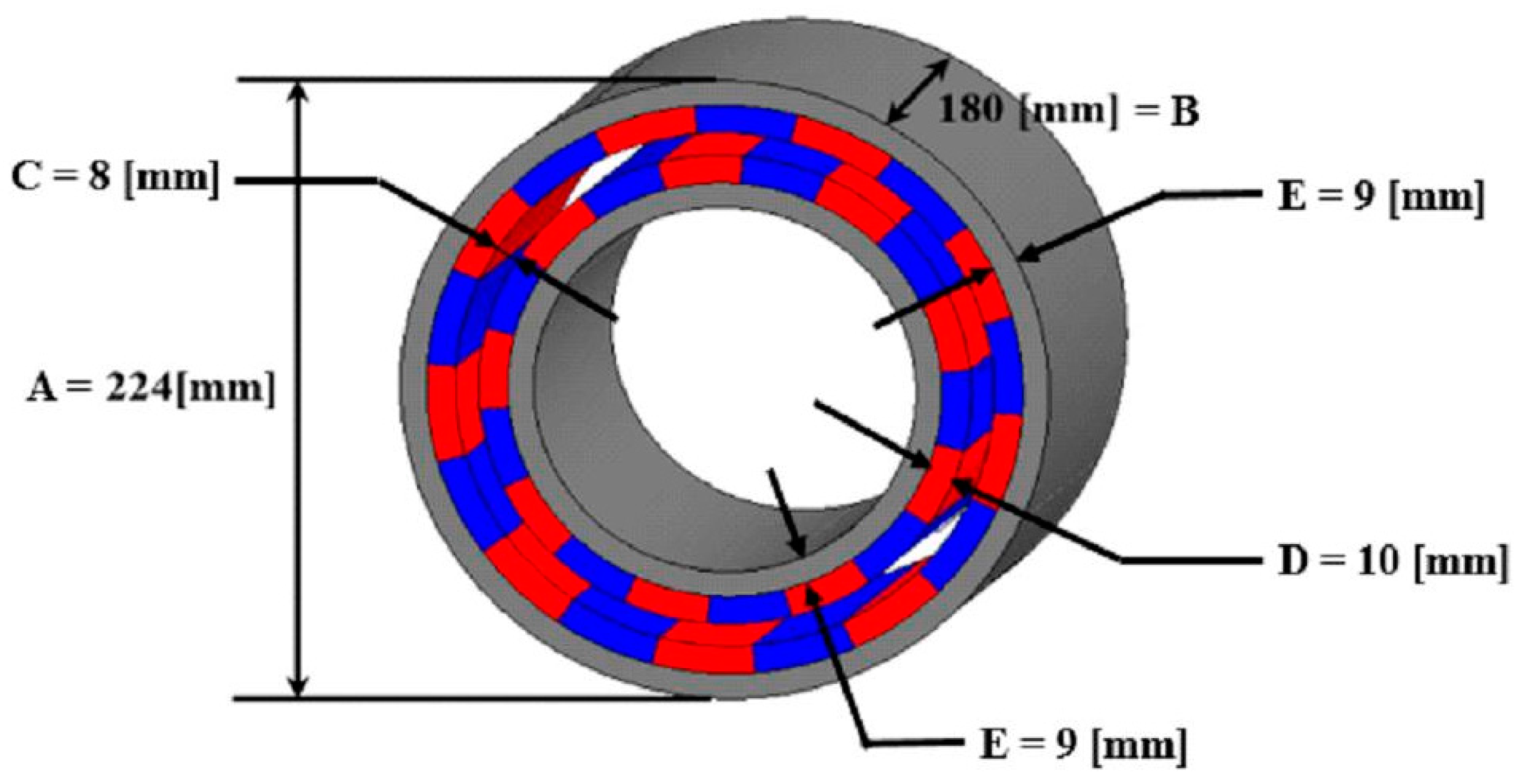
The coupling geometry, based on the specifications by Lee [
16], has an outer diameter of 80 mm, a length of 56 mm. The allowable torque was 72 kgf cm or 7.06 Nm [
17] which ensures that the coupling does not separate while the turbine is rotating.
In addition to the geometry, the materials for the magnets are an important selection. Ferrite, Alnico or rare earth elements are ferromagnetic and are generally used for making magnetic materials. For this study, a sintered grade 50 M Neodymium magnet (NdFeB) was selected. This has the largest magnetic flux density (Br = 1.4 T) for rare earth materials. The properties of the magnet are shown in
Table 1 below.
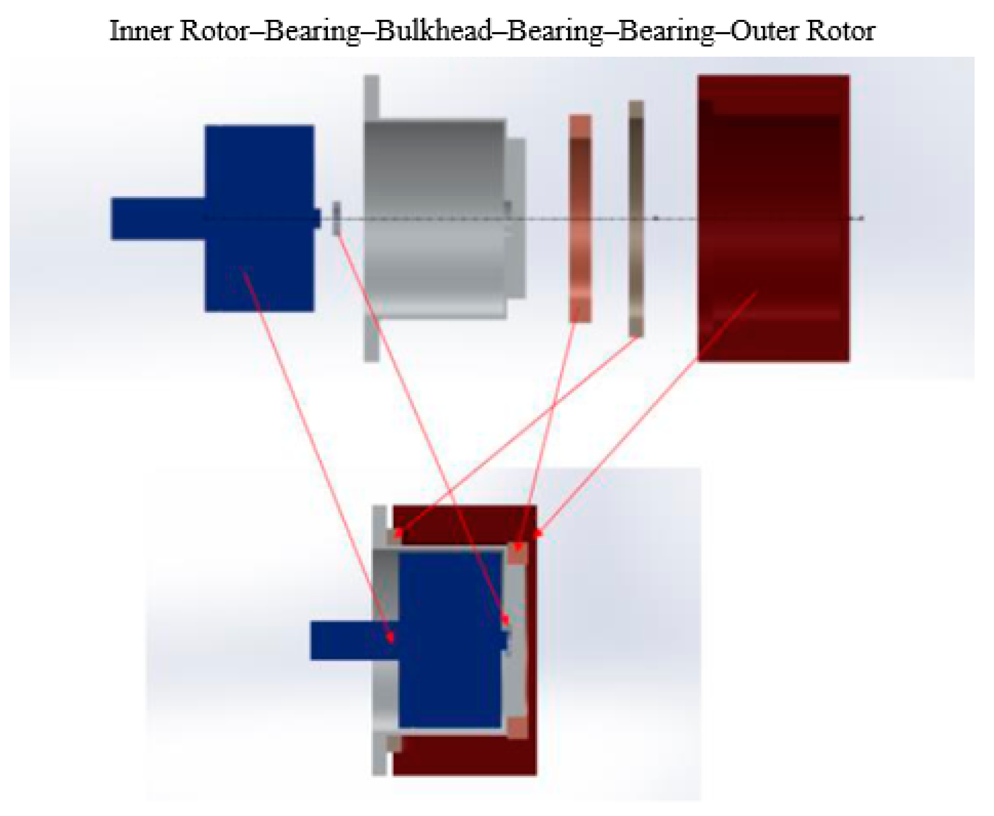
Figure 2 shows the assembly of parts that make the magnetic coupling. The arrows also indicate the location of each part. The bulkhead is installed in between the gap of the inner and outer rotor. A minimum gap distance of 3 mm between the inner and outer rotors is needed to allow for the installation of the bulkhead and necessary bearings. The bearings ensure that the outer rotor remains aligned when rotating. Furthermore, the magnet configuration is important in ensuring the coupling stays attached.
There are two main configurations that will be investigated in this paper; Type A and Type B as shown in
Figure 3. Type A uses eight magnets arranged end to end in order to fully utilizes the space within each rotor. However, the design of Type B takes into account the magnetic field of nearby magnets and reduces the size of the eight magnets. By varying the size of magnets, it is possible to produce similar magnetic strength with less material.
Another two variations on Type A, namely Type C and D have an increased air gap and the back yoke removed respectively. The purpose of these variations is to identify how these changes will influence the strength of the magnetic coupling. These four configurations of the magnetic coupling are summarized in
Table 2 below.
1.3. Combined Small-Scale Magnetic Coupling and Marine Current Turbine
Figure 4a–c shows the differences in the two small scale models.
Figure 4a shows assembly of mechanical oil seal coupling, various hub connections and key and shaft design of the previous marine current turbine.
Figure 4b shows assembly of new magnetic coupling and
Figure 4c shows 3D rendering of magnetic assembly.
The turbine’s rotating blades is connected to the external casing of the magnetic coupling via shaft as shown in
Figure 4b. The external casing closely fits and freely rotates over the fixed watertight seal/wall labeled in
Figure 4c. The seal prevents water from entering the hub. An internal shaft also has a close fit inside the seal. A bearing within the seal ensures the internal shaft has smooth rotation. The rotation of external housing over the seal causes the rotation of the internal shaft using the magnetic attraction between them.
The previous design of the oil seal (
Figure 4a) had a connecting rod which was used to connect to the internal gearbox whereas the magnetic coupling does not need a connection between the internal and external parts. The performance characteristics of the turbine with the new coupling method are discussed in the results section.
The following section will present the numerical analysis methodology of the four magnetic configurations, the experiment procedure on a small scale model of the magnetic coupling, the test of air and water tightness on magnetic coupling, and the experimental method used for the small scale combined magnetic coupling and turbine.
7. Conclusions
This paper presented the design of a magnetic coupling for a marine current turbine. The paper presented small scale experiments and CFD analysis on a 40 W model then additional analysis on the 10 kW design.
Four different configurations of the magnetic coupling were initially tested and the Type A configuration was selected. The magnetic coupling design was compared to the mechanical oil seal design in a previous study of the counter-rotating marine current turbine. In addition, the two experimental results were compared with the results of a CFD analysis of the turbine.
The magnetic coupling setup showed an increase of about 5% power output of 122.84 ± 4.84 W compared to 116.07 ± 4.21 W from the previous study. The magnetic coupling design also had reduction of about 17% in mechanical losses. The magnetic design had power coefficient of 0.46 ± 0.06 compared to 0.45 ± 0.06 obtained by the oil seal assembly. Furthermore, the magnetic coupling case was also in close agreement with the CFD results and had a more gradual decrease in the coefficient of power (Cp) values as the velocity increased.
This paper then presented four numerical analysis conducted on the 10 kW magnetic design:
The first analysis used MAXWELL that determined that a magnetic leak occurred across adjacent magnets. A non-magnetic region will added to optimize the design.
The second analysis was a 3D finite element analysis also showed that the design over varying load angles had maximum torque of about 1190 Nm. This value is within the safety factor and is expected that the magnetic coupler will not decouple during operation.
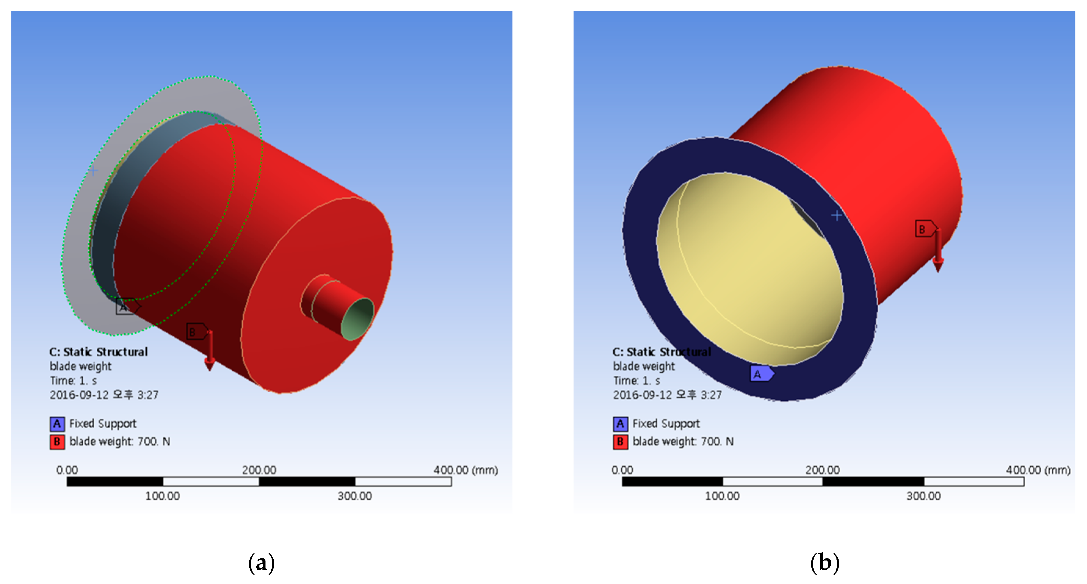
The third analysis tested the strength of the material by varying the bulkhead wall thickness and weight of the blades and hub. The maximum stress of 2.713 MPa occurs when the wall is 3 mm wall thick and a blade/hub weight of 1500 N. When compared with the yield strength of the material, 240 MPa, the material is expected to withstand the load.
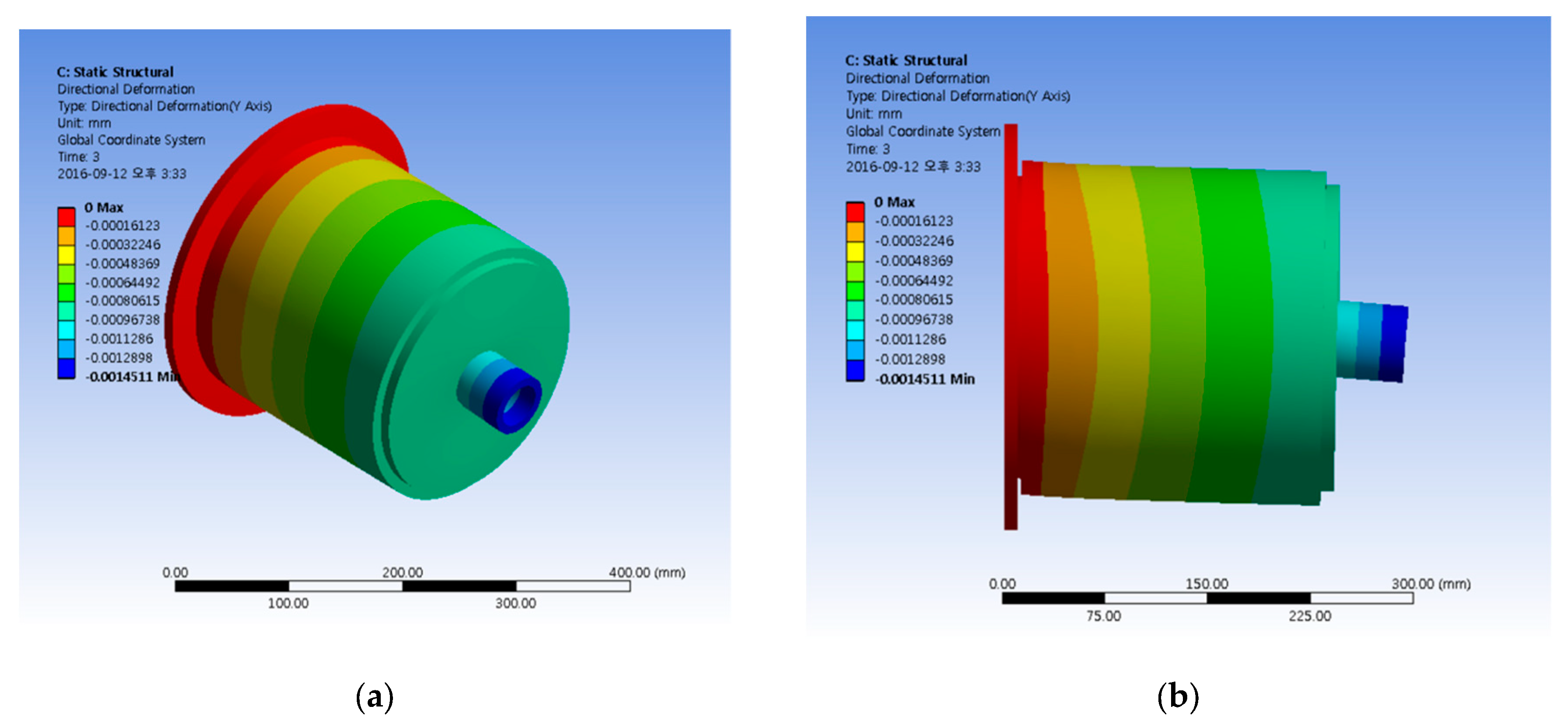
The final analysis presented showed that the maximum deflection of 2.29 × 10⁻³ mm will not interfere in the 2 mm gap between the bulkhead and outer rotor.
The magnetic coupling fulfilled the project’s requirement of watertight design for the hub. The design also had the advantage of lower torque losses and this design can be applied to other marine current designs, whether single or dual rotor.
The findings will be applied to design and manufacture a 10 kW prototype that is expected to be tested in real seas in the future.


