Article

The Power and Efficiency Analyses of the Cylindrical Cavity Receiver on the Solar Stirling Engine

1
Department of Mechanical Engineering, Graduate School, Hoseo University, Asan 31499, Korea
2
Division of Mechanical and Automotive Engineering, Hoseo University, Asan 31499, Korea
*
Author to whom correspondence should be addressed.
Energies 2020, 13(21), 5798; https://doi.org/10.3390/en13215798
Submission received: 8 September 2020 / Revised: 15 October 2020 / Accepted: 30 October 2020 / Published: 5 November 2020
(This article belongs to the Special Issue Heat Transfer Characteristics of Heat Pipes)

Abstract

:
The technique of solar dish and Stirling engine combination is the most challenging and promising one. For the efficient conversion of the externally concentrated heat to the usable power, we studied the influences of the wall temperature, inclination angle, and open area ratio of the receiver on the Stirling engine power and efficiency. The theoretical analysis of the heat exchange element of the solar Stirling engine was performed, and the simulation model of the cavity absorber was built and analyzed. The temperature cloud and heat loss trends of the receiver under different wall temperatures, inclination angles, and opening ratios were illustrated. When the wall temperature of the absorber changes from 700 to 1000 K, the efficiency of the engine has increased by 8.8% from 21.34% to 30.11%. The higher the temperature, the higher the efficiency. As the inclination angle of the absorber increases from 0° to 60°, the efficiency of the engine is increased by 7.7% from 21.1% to 28.8%. With the increases of the aperture ratio, the engine output and efficiency reduced. The engine efficiency at the aperture ratio of 0.5 is 4% larger than that at the aperture ratio of 1.

1. Introduction

Energy is the cornerstone of human society and the driving force for its development. Facing the challenge of depletion of fossil fuel energy, countries in the world have been paying close attention to the new energy source development in recent years [1,2,3,4,5]. The green power, such as the solar power, its generation development has become a great interest in its significant potential for several countries [6]. Until now, solar thermal technology has already made good progress in technology, research and development, commercialization application, and so on. Solar thermal power technique is attractive for its clean, efficient, and flexible advantages [7]. Currently, there are mainly three solar power generation system types: tower type, trough type, and dish type [8,9,10]. Dish solar power generation systems have relatively simple structures, flexibility, and high conversion efficiency. Its tropic photoelectric conversion can reach up to 30%, but tower type is about 10% only [11,12,13]. Overall, it is commercially prospective for its cost effectiveness.
Generally, a plate solar power generation system has four parts: a solar concentrator, an absorber, a Stirling engine, and a generator [14]. The solar concentrator is a rotating parabolic-shaped device. The paraboloid is made of highly reflective material and is used for sunlight reflection and concentration, and equipped with a solar tracking system. It can always aim at the sun, and most of the sunlight reflection on its surface is shown at the parabolic focus position. It is used to place the absorber in the focus position of the solar concentrator and to absorb solar heat collected at the focus. The Stirling engine heater is installed inside the absorber, where the solar heat enters into and whose heat is absorbed by the fluid in the heater of the Stirling engine. The receiver is a device that concentrates solar radiations into heat in the solar Stirling engine thermal power generation system. It is the most important part of the system. By connecting one generator to a Stirling engine, the power output from the engine can be converted to electrical energy [15].
The cavity receiver of solar Stirling engine plays an important role in heat conversion. It should be noted that all of its heat loss will reduce the energy efficiency of concentrated solar energy. The literature shows that numerous works have been conducted to design and analyze a cavity receiver of the parabolic dish Stirling module since 1980s. Thermal performance and heat losses of the solar receiver cavity have been studied by Natarajan et al. [16]. Wu et al. [5] have analyzed a receiver model for heat loss analysis. Wu et al. [17] studied the parabolic solar dish-Stirling system performance. The study showed that the power output and total efficiency of the Stirling engine were 18.54 kW and 20.6%, respectively. A global thermal model of 10 kW Euro dish/Stirling energy conversion was presented by Nepveu et al. [18]. A mathematical model was presented showing the influence of absorber temperature and the concentrating ratio on the thermal efficiency [19]. A simulation study has been conducted to check the wind impact on combined free-forced convection loss of solar cavity receiver. The results showed that under some wind conditions, the combined convective heat loss may be reduced below the natural convection value, and there was a critical wind speed to minimize the combined convective heat loss [20]. Neber et al. [21] have studied and analyzed the feasibility of cylindrical cavity receiver technology. Wang et al. [22] studied two new cylindrical cavity receivers with convex bottom surfaces to improve the optical efficiency. Results showed that the cavity receiver with bottom surface interior convex (BSIC) improved optical efficiency. A three-dimensional simulation analysis was carried out by Wu et al. [23], who reported the influence of some key parameters on the Nusselt number of convective heat loss and radiant heat loss. The rim angle study on the cavity flux distribution was made by Sup et al. [24]. Results showed that the optimum parabolic dish angle was important to achieve high focus point intensity. Ahmadi et al. [25] have been focusing on the solar dish-Stirling engine in respect to the thermal efficiency, output power, entropy generation’s rate, and entrance loss rate, with finite-time thermodynamics and multiobjective optimization employed. Gholamalizadeh et al. [26] analyzed the performance of the cavity receiver under various inclinations. Results showed that a pilot was installed with collector designed with a 45° rim angle. A mathematical model of a Scheffler-type solar concentrator with a Stirling engine was developed by Ruelas et al. [27]. In order to achieve higher heat efficiency, Li et al. [28] proposed a new geometrical receiver. For heat loss analysis, different types of cavities, including semispherical, cylindrical, and rectangular receivers, were used and a number of correlations were developed. A lot of research on the reduction of heat transfer loss has been carried out on the cavity receiver, the purpose was to maximize the Stirling engine to obtain more energy [29,30,31,32]. An analytical model to predict the receiver input energy, thermal losses, and thermal efficiency was developed by Gholamalizadeh et al. [33]. The results illustrated that the conduction losses were small, while the convection and the radiation losses played an important role in the total heat loss through the receiver. The convection losses dominated in special period of time, i.e., early morning and later evening, while the radiation losses reached their highest values around noon.
However, all these studies were based on the cavity receiver geometry and therefore, lacked the universal applicability for cavity receiver heat loss analysis, and there were a few studies on the Stirling engine output power and efficiency combined with the heat loss analysis of the cavity receiver.
The present study has two main highlights based on previous work review. One is the estimation of heat loss within the cavity receiver using a CFD model including modified standard k-ω turbulence. We simulated the effects of different wall temperatures, different angles, and different opening ratios on the heat losses of conduction, convection, and radiation. Another, the Stirling engine output energy and thermal efficiency were calculated combining the Stirling engine output power calculation method with the simulated heat losses results.

2. A Heat-Pipe Receiver

The cavity receiver device concentrates solar radiations into heat in the solar Stirling engine thermal power generation system. There are generally three heat transfer methods for the cavity receiver: direct illumination type, reflux type, and heat transfer method with heat storage system. Compared with the other two types, the direct-illuminated receiver has clear design ideas, simple structure, relatively mature technology, and easy implementation, so it is widely used. However, this type of receiver has some shortcomings. The uneven distribution of solar energy after focusing may make a large temperature difference between the absorber cavity and the heater surface, resulting in higher temperatures in certain locations. It is essential to simulate and analyze the temperature characteristics of the Stirling engine absorber cavity. Receiver’s parabolic dish energy balance, as shown Figure 1.
The heaters of the dish solar Stirling engine are generally placed in the absorber cavity, and the cavity generally uses a heat-resistant ceramic material. The high and low absorber efficiencies directly affect the Stirling engine’s photoelectric conversion efficiency, and due to the sun light’s nonuniformity and the time-dependent nature, relatively large temperature gradients and thermal stresses occur in the absorber cavity and wall. If the temperature gradient or thermal stress is too great, the absorber will deform or rupture, affecting the operational efficiency and stability of the Stirling engine [35].
The cavity receiver heat loss, including that of radiation, convection, and conduction, plays a major role in light-heat conversion. The radiation heat loss quantity depends on the cavity receiver wall temperature, shape factors, and emissivity/absorption rate, while the conduction heat loss depends on the cavity receiver wall temperature and the insulating material.
The cavity receiver heat loss is the combination heat losses of the conduction, the convection, and radiation [36].
Q l o s s = Q r a d + Q c o n v + Q c o n d .
(1)
Radiation loss
The receiver’s radiation loss occupies a significant fraction of the receiver total heat loss.
ε f = ε w 1 ( 1 ε w ) / ( 1 A J C / A J W )
Q r a d = ε f δ b ( T w a l l 4 T a m b 4 ) A J C ,
where ε f , ε w , δ b , T w a l l , and T a m b are the solar receiver emissivity, the cavity wall material heat emissivity, Stefan–Boltzmann constant, cavity wall temperature, and the ambient temperature, respectively.
(2)
Convection thermal loss
The natural convection heat transfer coefficient inside the receiver cavity is given by:
N u J = 0.088 G r L 1 3 ( T r e c T a m b ) 0.18 ( c o s θ q ) 2.47 ( d a q L q ) s
s = 1.12 0.98 d a p L q
Q c o n v = h c o v ( T r e c T a m b ) A J C = N u J λ j ( T r e c T a m b ) d a p d r e c ,
where N u J , G r L , θ q ,   d r e c ,   d a p ,   h c o v , and λ j are the Nusselt number, the Grashof number, the angle of inclination of the cavity axis, the absorber cavity diameter, the opening surface diameter, natural convection heat exchange coefficient, and air heat conduction coefficient, respectively.
(3)
Conduction heat loss
The conduction heat loss represents a small total receiver thermal loss proportion. The conduction heat transfer depends on the receiver material thermal conductivity λ r e c and its wall thickness Δ z , as following:
Q c o n d = λ r e c Δ z A J C ( T r e c T a m b )
Q u = Q a Q r a d Q c o n v Q c o n d ,
where Q u and Q a are solar thermal energy received by the absorber and heat energy received by the heater of Stirling engine, respectively [37].

3. The Absorber Cavity Model’s Thermal Performance

The effects of different operating and geometric parameters on convective and radiant heat loss are discussed in this chapter, and the temperature and flow field distributions of the common heat sink are obtained.

3.1. Cavity Absorbing Model

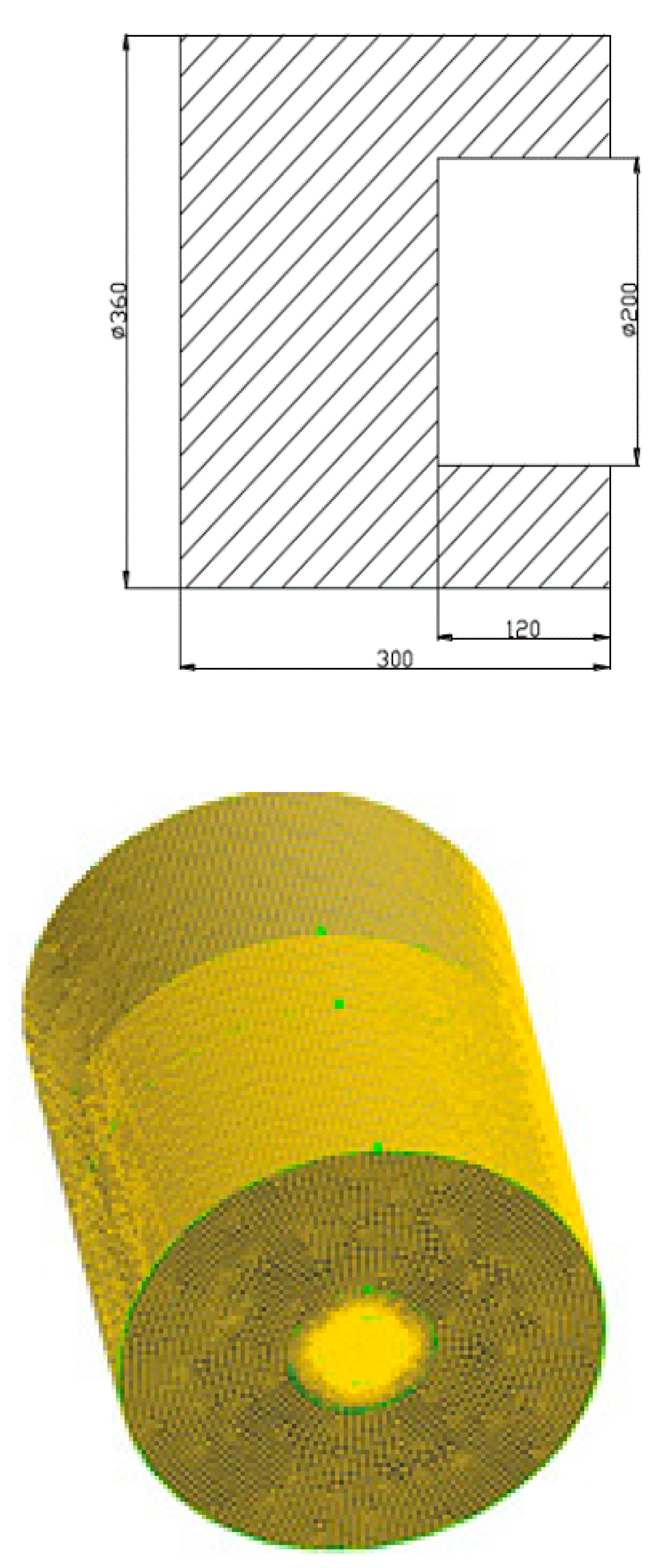
The cavity receiver geometry used for simulation is illustrated in Figure 2. The geometry is divided into two areas: a fluid-filled area and a solid area. The geometric model of the heat sink is divided into three different grid sizes (a: 639,860 cells, b: 803,190 cells, and c: 1,412,580 cells), using a combination of structured and unstructured grids. By comparing and analyzing the calculation results, it is determined to adopt (b) grid structure, thus it can not only meet the requirements of computing resources but also accurately display the flow field.

3.2. Simulation Method

In this study, a solver based on 3D pressure was applied to the numerical simulation for the compressed hydrogen gas cycling. PISO algorithm for numerical calculation.
The user-defined function expanded and improved the simulation calculation model; this model used pressure and velocity coupling algorithms. Discrete calculation methods were standard pressure dispersion, momentum equation, turbulence energy and its dissipation rate calculation equation and the energy equation that used first-level upwind dispersion, and first-level implicit instantaneous equation.
Thermal performance of absorber cavity model requires a static solution. The step is set to be 0.01 s to ensure grid convergence.

3.3. Model Validation

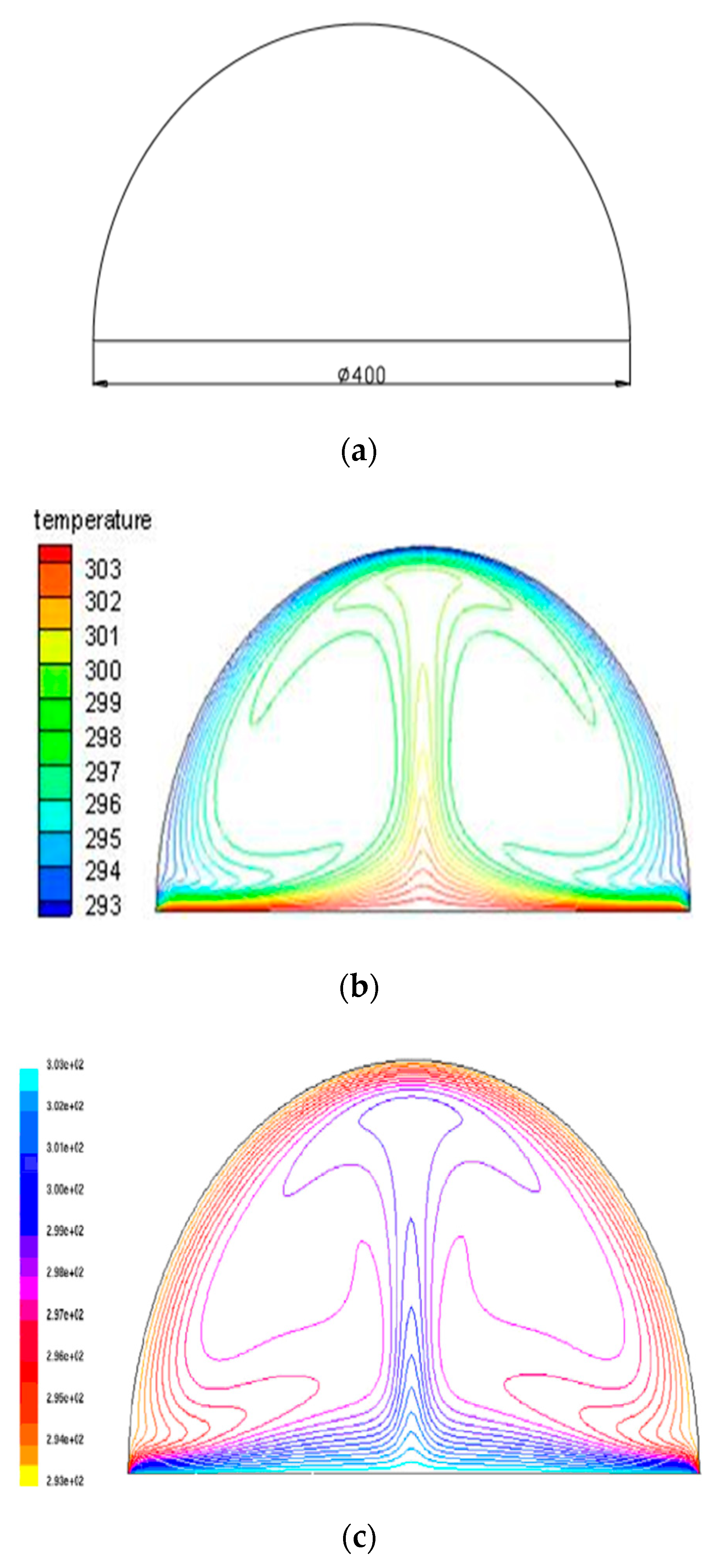
In order to determine the feasibility of the Fluent software to simulate the cavity receiver, the reference uses common cavity receivers (the semiempirical model) as the object to compare with the results of the literature.
It can be seen from Figure 3 that the isotherm of the semicircular closed cavity is symmetrical along the central axis. The isotherms inside the cavity are sparse and the temperature difference is small; the isotherms near the cavity wall and the central axis are dense, and the temperature difference is large. Simulation result is in good agreement with the results of the literature [38].

3.4. Cavity Wall Temperature’s Effect on Thermal Performance

The cavity wall temperature is a very critical parameter, which directly affects the heat absorbed by the Stirling engine, which in turn affects the solar Stirling system output power and the generator efficiency.
Figure 4 is a diagram showing the temperature distribution in cavity receiver when the absorber installation wall temperature is 700, 800, 900, and 1000 K under 0° inclination angle. The cavity heat sink temperature distribution at different wall temperatures is similar.
There is a large temperature gradient between the wall and the environment, as the cavity wall temperature is high and ambient temperature is low. The cold air in the low temperature enters the heat absorber, flows along the inner wall at high speed, and receives most of the heat through the wall to be heated. After the cold air flows into the upper cavity part, due to the existence of the high-temperature gas stagnation area in the upper part of the cavity, the temperature rises and forms natural convection with the outside air, and the internal heat of the cavity heat sink is continuously taken out.
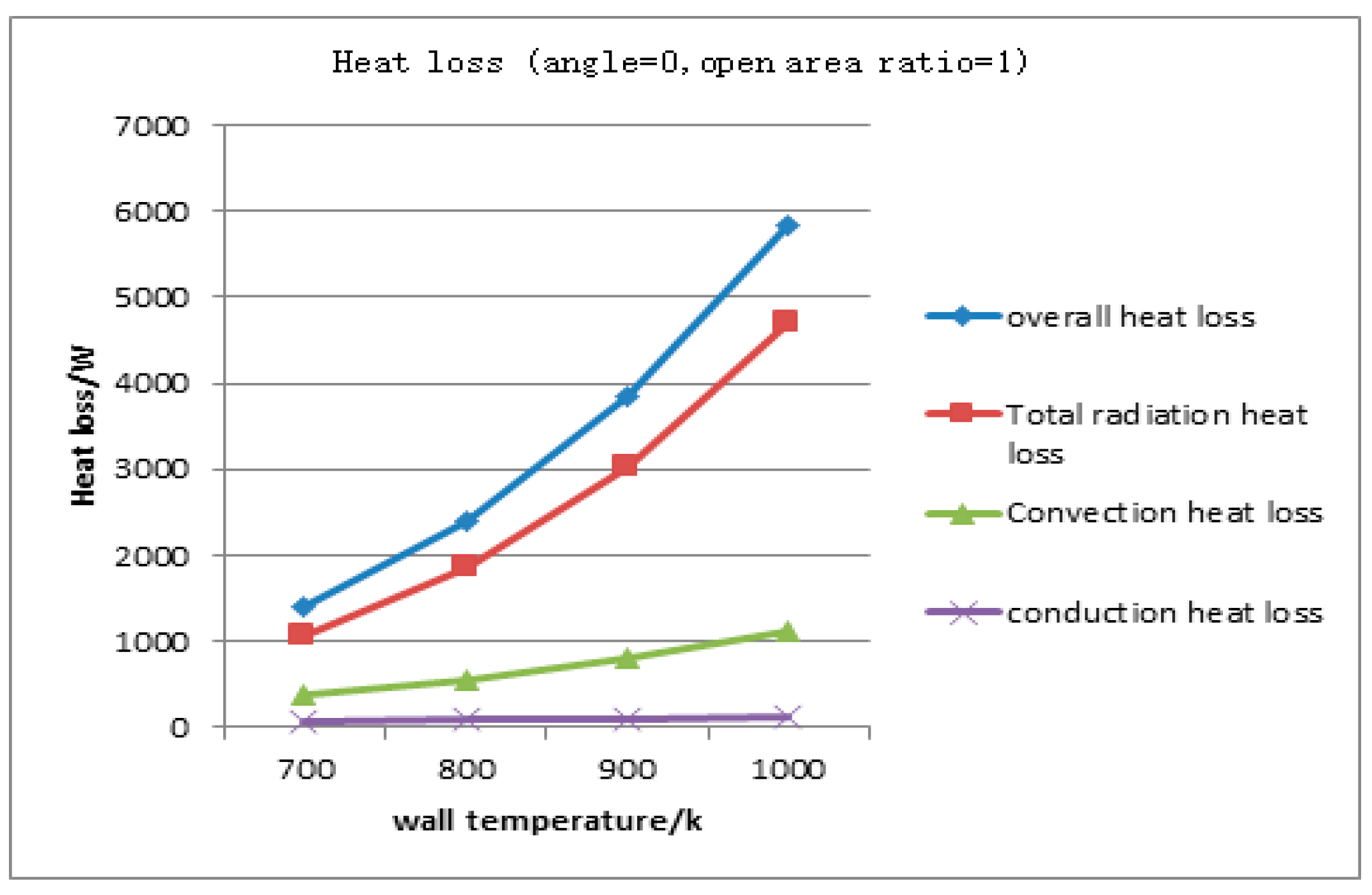
Figure 5 shows the cavity receiver heat loss at 0° inclination angle. With the temperature increasing, the natural convective heat loss and radiant heat loss increase, the ratio of the latter is more than that of the former, and the gap natural convective heat loss value increases significantly as well. The radiation heat loss is more than twice the natural convection heat loss in value. Therefore, the inner wall radiant heat loss should be reduced as much as possible, so as to reduce the cavity heat sink heat loss at high operating temperature.

3.5. Heat Absorbing Inclination Angle’s Effect on Thermal Performance

It can be seen from Figure 6 that with the inclination angle increasing, the high temperature stagnation zone in the heat absorber cavity increases and the heat exchange with the outside decreases. When the inclination angle is 0°, the fluid enters from the cavity bottom, gets heat from the cavity wall, and flows out from the top of the cavity under the action of buoyancy. When the inclination angle is 30°, the cavity receiver has a large temperature gradient on the opening plane, and the existence of this temperature gradient appropriately prevents the outside cold air from entering the cavity receiver. At 60° inclination angle, the high temperature stagnation area inside the heat sink is larger. The greater the inclination angle, the sparser the isothermal lines in the cavity, and the smaller the temperature gradient near the wall, the weaker the natural convection effect. At 90° inclination angle, most of the cavity is a high temperature area, and the temperature distribution inside the cavity is relatively uniform, but there is still a small exchanging area at the opening and in external environment. The simulation calculation results are in good agreement with the literature results [40].
Figure 7 shows heat loss of cavity wall temperature of 900 K for inclination angles 0°, 30°, 60°, and 90°. As the inclination angle increases, the natural convective heat loss gradually decreases because the increase in inclination decreases the outlet of the heat sink relatively, weakening the natural convection and improving the heat absorber internal temperature distribution. At 90° inclination, the natural convection heat loss value is not 0. Radiation heat loss according to the trend of change did not change. The angle of inclination only affects the cavity heat sink natural convective heat loss, and it constantly changes during the operation of the system. Result show that, a larger inclination angle is beneficial to suppress the cavity receiver natural convection and to improve its thermal performance.

3.6. Effect of Open Area Ratio on Thermal Performance

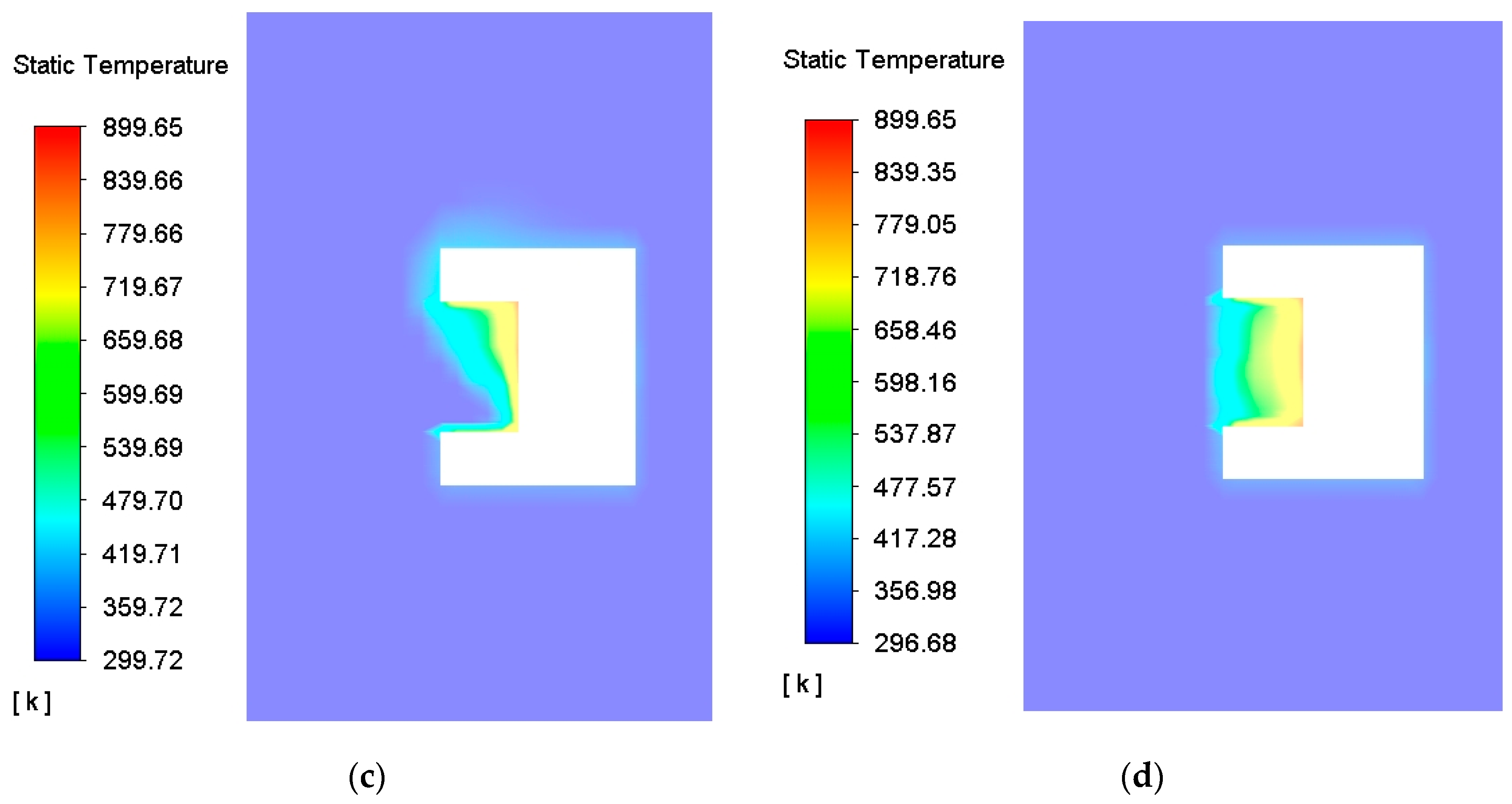
In practical applications, the opening area of the cavity receiver must be large enough to receive as much solar energy as possible; on the other hand, it must be small enough to minimize the external cavity receiver heat loss. The receiver opening ratio will determine the receiver opening area size and is also a key factor affecting the cavity receiver’s thermal performance.
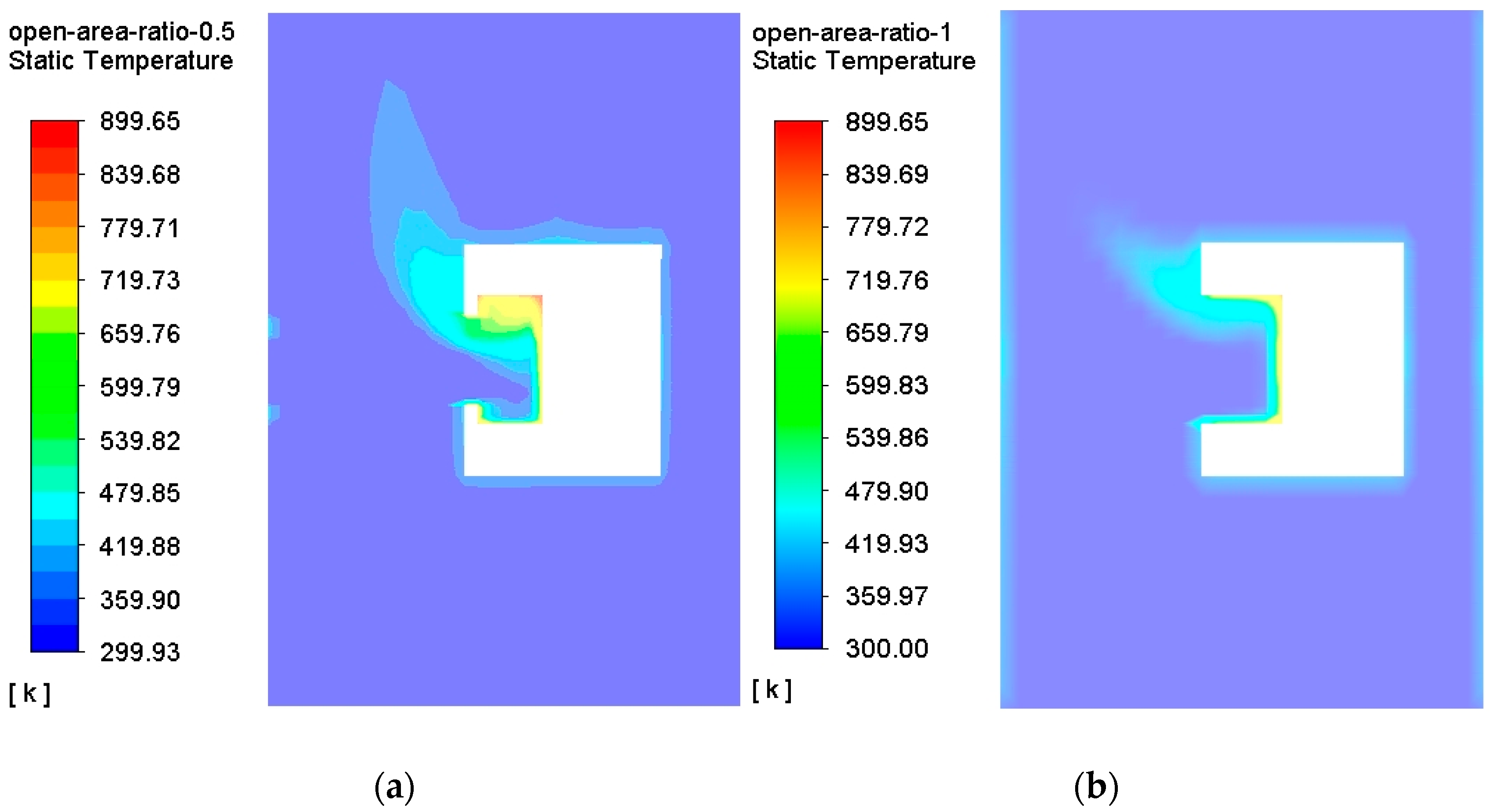
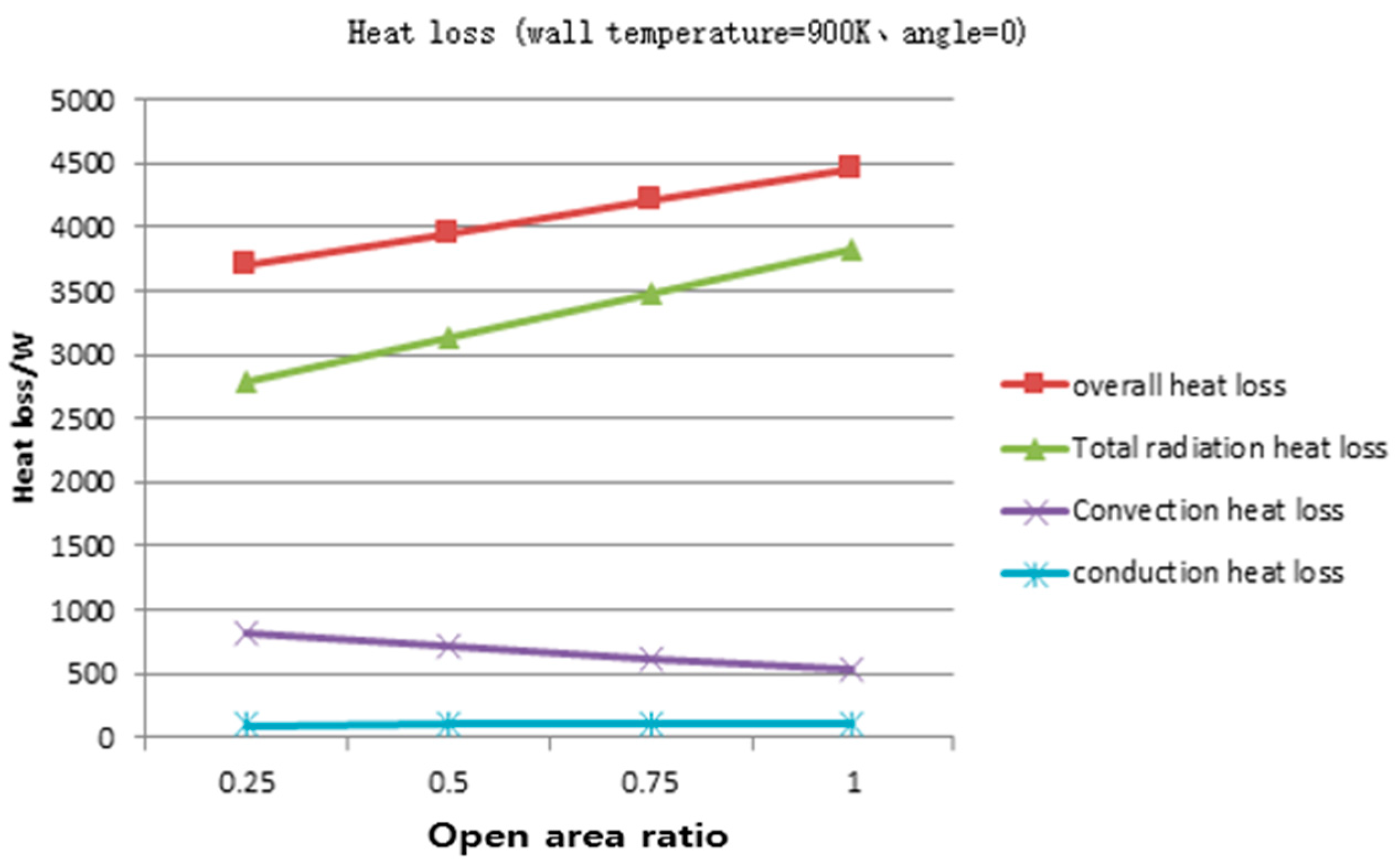
According to Figure 8, as the opening ratio of the cavity type heat exchanger is decreased, the opening area of the heat absorber is gradually decreased, so that hot air does not overflow inside the heat absorber while preventing hot air from entering the heat absorber. To some extent, it reduces cavity heat sink and its external heat transfer. In a heat exchanger that dissipates heat simultaneously with the outside, the temperature distribution of the internal heat absorber becomes more uniform, and the non-uniformity of the temperature distribution due to heat loss decreases, thereby gradually improving the heat sink performance. However, the smaller the opening ratio of the cavity heat sink, the higher the requirements for light concentration, the more complex the structure, and the higher the cost. Therefore, the opening ratio should be controlled within a certain range. The 900 K cavity wall temperature contours for different open area ratio 0.25, 0.5, 0.75, and 1, as shown Figure 9. Result shows that, as the opening ratio decreased, the cavity receiver natural convection heat loss and radiant heat loss were reduced, and the opening ratio had a greater impact on the radiation heat loss, as well as on the total heat loss.
  • As the absorber wall surface temperature increased, both cavity natural convection heat loss and radiation heat loss increased. The wall temperature was 700, 800, 900, and 1000 K at 0° inclination angle, and the radiation heat loss to the total heat loss ratio was 74.16%, 76.64%, 78.78%, and 80.72%, respectively. The ratio of natural heat loss was small.
  • With the angle increased, the overall heat loss of the convection was reduced. At 900 K wall temperature, the inclination angle was 0°, 30°, 60°, and 90°, and the convection heat loss to the total heat loss ratio was 21.22%, 14.19%, 13.25%, and 9.29%, respectively. If the inclination angle was large, the natural convection heat sink can be suppressed.
  • As the opening ratio decreased, the cavity receiver natural convection heat loss and radiant heat loss were reduced, and the opening ratio had a greater impact on the radiation heat loss, as well as on the total heat loss. The optimized setting of the opening ratio parameter is meaningful to reduce the heat absorber heat loss and improve the thermal performance. Based on the findings of the cavity receiver internal temperature distribution characteristics and its heat loss characteristics, structure optimization was an effective way to improve the dish solar Stirling thermal power and efficiency.

4. Stirling Engine’s Output and Efficiency

Dish Stirling engine simulation block diagram, as shown Figure 10. In general, a plate solar power generation system consists mainly of a solar collector, an absorber, a Stirling engine, and a generator. The absorber is placed at the focal point of the solar collector, and it absorbs the solar heat collected in the focus. The solar heat entering the absorber is absorbed by the fluid of the heater installed inside the Stirling engine. The fluid converts solar heat into thermal energy and provides a heat source for the Stirling engine. By connecting one generator to Stirling engine, the engine power output can be converted into electrical energy.
Q a = η o p t I D N Γ A c o n ,
where η o p t is the collector optical efficiency ( η o p t = 0.94 ) . I D N is the direct normal irradiation, I D N = 950   W / m 2 . A c o n is area of the concentrator, D c o n = 3 m. Γ is the day angle radians, Γ = 2 π ( N 1 365 ) . N in this model is the day number of in 1 year, ranging from 1 (on 1 January) to 365 (on 31 December). The average value of Γ is 3.14.
Q u = m c p d T r e c d t = A r e c [ P o p t U g l o b ( T r e c T a m b ) ]
U g l o b = h c o n d + h c o n v + h r a d
P o p t = η o p t I D N C g
T r e c ( t ) = T a m b + ( P o p t U g l o b T ( t 0 ) + T a m b ) × e [ U g l o b m c p × A r e c × ( t t 0 ) ]
t   T r e c ( t ) = T a m b + P o p t U g l o b
h r a d = ε f δ b ( T r e c 2 + T a m b 2 ) ( T r e c + T a m b ) h c o n d = k l h c o n v = λ j d r e c N u J ,
where U g l o b is the global coefficient of heat loss (W/m2 K). C g is the geometric concentration ratio. l = 70 mm. Theoretical calculated the average cavity temperature and wall temperature, as shown in Table 1.

4.1. Wall Temperature Effect on Stirling Engine’s Power and Efficiency

The Stirling engine output and efficiency are predicted while changing the temperature of the cavity wall. Table 2 shows the results.
Q a = T w a l l T r e c R c o n d
R c o n d = ln ( r 2 / r 1 ) 2 π l k ,
where r 2 is cavity receiver inner radius (mm), r 1 is aperture radius (mm), and l is cavity receiver height (mm).
Figure 11 shows Stirling engine output power and efficiency during the useful power for different wall temperatures [40]. As the absorber wall temperature increases, both the engine’s power and efficiency values increase. When the absorber wall temperature changes from 700 to 1000 K, the engine efficiency increases by 8.8% from 21.34% to 30.11%. The higher the temperature, the higher the efficiency.

4.2. Incline Angle Effect on Stirling Engine’s Output and Efficiency

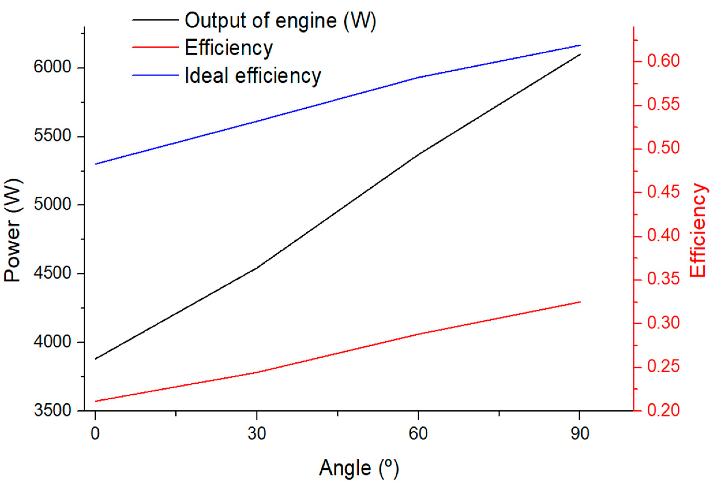
In Figure 12, as the absorber inclination angle increases, the engine’s output power and efficiency increases. When the inclination angle of the absorber is changed from 0° to 60°, the engine efficiency increases by 7.7% from 21.1% to 28.8%.

4.3. Open Area Ratio Effect on Stirling Engine’s Output and Efficiency

Table 3 shows Stirling engine’s output power and efficiency for different open area ratio. With the increase in the aperture ratio, the engine power and efficiency are decreased, and the engine efficiency at the aperture ratio of 0.5 was 4% higher than that at the aperture ratio of 1.

5. Results

In this paper, the Stirling engine solar thermal power generation technology is taken as the background, and the cavity receiver, an important component of the system, as the research object. Through the related convection heat and radiation heat transfer theories, the cavity receiver model is rationalized and simplified and assumed, and then related thermal performance simulation is analyzed. Finally, the Stirling engine isotherm calculation method is used to obtain the engine output power and efficiency.
  • Cavity receiver thermal performance
    (1)
    The cavity receiver temperature field distribution under different wall conditions is similar. Cold air enters from the bottom of the receiver. After being heated by the wall, it flows upward along the inner wall and finally flows out from the upper area of the heat absorber opening.
    (2)
    The higher the wall temperature, the greater the proportion of radiant heat loss, and the radiant heat loss increasing rate is significantly greater than the natural convection heat loss. The greater the wall emissivity, the more obvious the effect of radiant heat transfer and the greater the value of radiant heat loss, but the wall emissivity has no influence on natural convection heat transfer.
    (3)
    The cavity receiver heat loss decreases as the tilt angle increases. Simultaneously, the high temperature stagnation zone in the receiver cavity increases, and the convective heat transfer with the outside decreases. The greater the inclination angle, the lower the natural convection heat loss, and the value of radiant heat loss has nothing to do with the inclination angle.
  • Stirling engine’s power and efficiency
    Results show that as the absorber wall temperature increases, both the engine output power and efficiency increase.
    (1)
    When the absorber wall temperature changes from 700 to 1000 K, the efficiency of the engine has increased by 8.8% from 21.34% to 30.11%. The higher the temperature, the higher the efficiency.
    (2)
    As the absorber inclination angle increases, the engine output and efficiency increase. The engine efficiency increased by 7.7% from 21.1% to 28.8% when the tilt angle of the absorber changed from 0° to 60°.
    (3)
    With the increase in the aperture ratio, the engine output and efficiency reduced, and the engine efficiency at the aperture ratio of 0.5 was 4% larger than that at the aperture ratio of 1.

Author Contributions

Conceptualization, J.-T.K. and S.-J.J.; methodology, J.-T.K.; software, J.-Q.L.; validation, S.-J.J. and J.-T.K.; formal analysis, J.-Q.L.; investigation, J.-T.K.; resources, J.-Q.L.; data curation, J.-Q.L.; writing—original draft preparation, J.-Q.L.; writing—review and editing, J.-Q.L.; visualization, J.-Q.L.; supervision, J.-T.K.; project administration, S.-J.J.; funding acquisition, S.-J.J. All authors have read and agreed to the published version of the manuscript.

Funding

This study was a research project conducted by the Ministry of Trade, Industry and Energy and supported by the Korea Energy Technology Evaluation Institute (KETEP) as an energy technology development project. (No. 2017301004183, No. 20183010041940).

Conflicts of Interest

The authors declare no conflict of interest.

Nomenclature

A JC internal cavity area m 2
A JW solar receiver area m 2
A con area of the concentrator, m 2 ( D con = 3   m )
d rec cavity receiver inner diameter, (cm)
d ap aperture diameter, cm
Q a absorbed solar radiation (W)
Q loss total heat loss (W)
Q u total input thermal power of Stirling engine
Q cond heat loss from the conduction (W)
Q conv heat loss from the convection (W)
Q rad heat loss from the radiation (W)
T wall cavity receiver wall temperature (K)
T amb ambient temperature (K)
T rec temperature of the cavity receiver (K)
ReReynolds number
Nu J the Nusselt number
Gr L the Grashof number
k thermal conductivity ( W / m · K )
h conv convective heat transfer coefficient of the cavity receiver ( W / m 2 · K )
h rad radiation heat transfer coefficient of the cavity receiver ( W / m 2 · K )
h cond conduction heat transfer coefficient from the cavity receiver to ambient ( W / m 2 · K )
I DN Incident solar flux intensity ( W / m 2 )
c p specific heat at constant pressure ( J / kg · K )
ttime (s)
U glob the global coefficient of heat loss ( W / m 2 · K ) , U glob = h cond + h conv + h rad
C g the geometric concentration ratio.
P opt Power output (W)
L q length of the cavity (m)
d aq diameter of interior cavity
Greek symbols
δ b the Stefan–Boltzmann constant. 5.627 × 10 8   W / m 2 · K 4
ε f the emissivity of solar receiver
ε w the heat emissivity of receiver wall material ( ε w = 0.8).
η opt the collector optical efficiency ( η opt = 0.94 )
Γ the day angle Γ (radians), the average value of Γ is 3.14.
θ q the cavity inclination ranging between 0 and π / 2
λ j air heat conduction coefficient ( W / m 2 · K )

References

  1. Shaulsky, E.; Boo, C.; Lin, S.; Elimelech, M. Membrane-Based Osmotic Heat Engine with Organic Solvent for Enhanced Power Generation from Low-Grade Heat. Environ. Sci. Technol. 2015, 49, 5820–5827. [Google Scholar] [CrossRef] [PubMed]
  2. Hafez, A.; Attia, A.; Eltwab, H.; Elkousy, A.; Afifi, A.; Abdelhamid, A.; Abdelqader, A.; Fateen, S.-E.; El-Metwally, K.; Soliman, A.; et al. Design analysis of solar parabolic trough thermal collectors. Renew. Sustain. Energy Rev. 2018, 82, 1215–1260. [Google Scholar] [CrossRef]
  3. Qandil, H.; Wang, S.; Zhao, W. Application-based design of the Fresnel lens solar concentrator. Renew. Wind Water Sol. 2019, 6, 3. [Google Scholar] [CrossRef]
  4. Barlev, D.; Vidu, R.; Stroeve, P. Innovation in concentrated solar power. Sol. Energy Mater. Sol. Cells 2011, 95, 2703–2725. [Google Scholar] [CrossRef]
  5. Wu, S.-Y.; Xiao, L.; Cao, Y.; Li, Y.-R. Convection heat loss from cavity receiver in parabolic dish solar thermal power system: A review. Sol. Energy 2010, 84, 1342–1355. [Google Scholar] [CrossRef]
  6. Mancini, T.; Heller, P.; Butler, B.; Osborn, B.; Schiel, W.; Goldberg, V.; Buck, R.; Diver, R.; Andraka, C.; Moreno, J. Dish-Stirling Systems: An Overview of Development and Status. J. Sol. Energy Eng. 2003, 125, 135–151. [Google Scholar] [CrossRef]
  7. Wu, Z.; Dai, W.; Man, M.; Luo, E. A solar-powered traveling-wave thermoacoustic electricity generator. Sol. Energy 2012, 86, 2376–2382. [Google Scholar] [CrossRef]
  8. Zhu, S.; Yu, G.; Ma, Y.; Cheng, Y.; Wang, Y.; Yu, S.; Wu, Z.; Dai, W.; Luo, E. A free-piston Stirling generator integrated with a parabolic trough collector for thermal-to-electric conversion of solar energy. Appl. Energy 2019, 242, 1248–1258. [Google Scholar] [CrossRef]
  9. AVING Special Report on Solar Power International; CA, USA, 2010; Available online: http://kr.aving.net/news/view.php?articleId=172098 (accessed on 5 November 2020).
  10. Hussain, T.; Islam, M.; Kubo, I.; Watanabe, T. Study of heat transfer through a cavity receiver for a solar powered advanced Stirling engine generator. Appl. Therm. Eng. 2016, 104, 751–757. [Google Scholar] [CrossRef]
  11. Cheng, C.-H.; Chen, Y.-F. Numerical simulation of thermal and flow fields inside a 1-kW beta-type Stirling engine. Appl. Therm. Eng. 2017, 121, 554–561. [Google Scholar] [CrossRef]
  12. Lai, X.; Long, R.; Zhi-Chun, L.; Liu, W. Stirling engine powered reverse osmosis for brackish water desalination to utilize moderate temperature heat. Energy 2018, 165, 916–930. [Google Scholar] [CrossRef]
  13. Hafez, A.; Soliman, A.; El-Metwally, K.; Ismail, I. Design analysis factors and specifications of solar dish technologies for different systems and applications. Renew. Sustain. Energy Rev. 2017, 67, 1019–1036. [Google Scholar] [CrossRef]
  14. Schiel, W.; Keck, T. Parabolic dish concentrating solar power (CSP) systems. In Concentrating Solar Power Technology: Principles, Developments and Applications; Lovegrove, K., Stein, W., Eds.; Woodhead Publishing: Cambridge, UK, 2012; pp. 284–322. [Google Scholar]
  15. Caballero, G.E.C.; Mendoza, L.S.; Martinez, A.M.; Silva, E.E.; Melian, V.R.; Venturini, O.J.; Del Olmo, O.A. Optimization of a Dish Stirling system working with DIR-type receiver using multi-objective techniques. Appl. Energy 2017, 204, 271–286. [Google Scholar] [CrossRef]
  16. Natarajan, S.K.; Reddy, K.; Mallick, T.K. Heat loss characteristics of trapezoidal cavity receiver for solar linear concentrating system. Appl. Energy 2012, 93, 523–531. [Google Scholar] [CrossRef]
  17. Wu, S.-Y.; Xiao, L.; Cao, Y.; Li, Y.-R. A parabolic dish/AMTEC solar thermal power system and its performance evaluation. Appl. Energy 2010, 87, 452–462. [Google Scholar] [CrossRef]
  18. Nepveu, F.; Ferrière, A.; Bataille, F. Thermal model of a dish/Stirling systems. Sol. Energy 2009, 83, 81–89. [Google Scholar] [CrossRef]
  19. Yaqi, L.; Yaling, H.; Weiwei, W. Optimization of solar-powered Stirling heat engine with finite-time thermodynamics. Renew. Energy 2011, 36, 421–427. [Google Scholar] [CrossRef]
  20. Xiao, L.; Wu, S.-Y.; Li, Y.-R. Numerical study on combined free-forced convection heat loss of solar cavity receiver under wind environments. Int. J. Therm. Sci. 2012, 60, 182–194. [Google Scholar] [CrossRef]
  21. Neber, M.; Lee, H. Design of a high temperature cavity receiver for residential scale concentrated solar power. Energy 2012, 47, 481–487. [Google Scholar] [CrossRef]
  22. Wang, F.; Lin, R.; Liu, B.; Tan, H.; Shuai, Y. Optical efficiency analysis of cylindrical cavity receiver with bottom surface convex. Sol. Energy 2013, 90, 195–204. [Google Scholar] [CrossRef]
  23. Wu, S.-Y.; Guo, F.-H.; Xiao, L. Numerical investigation on combined natural convection and radiation heat losses in one side open cylindrical cavity with constant heat flux. Int. J. Heat Mass Transf. 2014, 71, 573–584. [Google Scholar] [CrossRef]
  24. Sup, B.A.; Zainudin, M.F.; Ali, T.Z.S.; Abu Bakar, R.; Ming, G.L. Effect of Rim Angle to the Flux Distribution Diameter in Solar Parabolic Dish Collector. Energy Procedia 2015, 68, 45–52. [Google Scholar] [CrossRef] [Green Version]
  25. Ahmadi, M.H.; Mellit, A.; Pourfayaz, F.; Feidt, M. Thermodynamic analysis and multi objective optimization of performance of solar dish Stirling engine by the centrality of entransy and entropy generation. Int. J. Electr. Power Energy Syst. 2016, 78, 88–95. [Google Scholar] [CrossRef]
  26. Gholamalizadeh, E.; Chung, J.D. Design of the Collector of a Solar Dish-Stirling System: A Case Study. IEEE Access 2017, 5, 20754–20762. [Google Scholar] [CrossRef]
  27. Ruelas, J.; Velázquez, N.; Cerezo, J. A mathematical model to develop a Scheffler-type solar concentrator coupled with a Stirling engine. Appl. Energy 2013, 101, 253–260. [Google Scholar] [CrossRef]
  28. Li, S.; Xu, G.; Luo, X.; Quan, Y.; Ge, Y. Optical performance of a solar dish concentrator/receiver system: Influence of geometrical and surface properties of cavity receiver. Energy 2016, 113, 95–107. [Google Scholar] [CrossRef]
  29. Tan, Y.; Zhao, L.; Bao, J.; Liu, Q. Experimental investigation on heat loss of semi-spherical cavity receiver. Energy Convers. Manag. 2014, 87, 576–583. [Google Scholar] [CrossRef]
  30. Reddy, K.; Natarajan, S.K.; Veershetty, G. Experimental performance investigation of modified cavity receiver with fuzzy focal solar dish concentrator. Renew. Energy 2015, 74, 148–157. [Google Scholar] [CrossRef]
  31. Mao, Q.; Shuai, Y.; Yuan, Y. Study on radiation flux of the receiver with a parabolic solar concentrator system. Energy Convers. Manag. 2014, 84, 1–6. [Google Scholar] [CrossRef]
  32. Loni, R.; Kasaeian, A.; Asli-Ardeh, E.A.; Ghobadian, B.; Le Roux, W. Performance study of a solar-assisted organic Rankine cycle using a dish-mounted rectangular-cavity tubular solar receiver. Appl. Therm. Eng. 2016, 108, 1298–1309. [Google Scholar] [CrossRef]
  33. Gholamalizadeh, E.; Chung, J.D. Thermal Analysis of the Receiver of a Standalone Pilot Solar Dish–Stirling System. Entropy 2018, 20, 429. [Google Scholar] [CrossRef] [Green Version]
  34. Kadri, Y.; Abdallah, H.H. Performance evaluation of a stand-alone solar dish Stirling system for power generation suitable for off-grid rural electrification. Energy Convers. Manag. 2016, 129, 140–156. [Google Scholar] [CrossRef]
  35. Xie, W.; Dai, Y.; Wang, R. Numerical and experimental analysis of a point focus solar collector using high concentration imaging PMMA Fresnel lens. Energy Convers. Manag. 2011, 52, 2417–2426. [Google Scholar] [CrossRef]
  36. Mohammad, H.A.; Hoseyn, S.; Saeed, D.H.; Hadi, H. Esigning a solar powered Stirling heat engine based on multiple criteria: Maximized thermal efficiency and power. Energy Convers. Manag. 2013, 75, 282–291. [Google Scholar]
  37. Duffie, J.A.; Beckman, W.A.; Blair, N. Solar Engineering of Thermal Processes, 3rd ed.; John Willey & Sons Inc.: Madison, WI, USA, 2006. [Google Scholar]
  38. Reddy, K.; Kumar, N.S. Combined laminar natural convection and surface radiation heat transfer in a modified cavity receiver of solar parabolic dish. Int. J. Therm. Sci. 2008, 47, 1647–1657. [Google Scholar] [CrossRef]
  39. Kumar, N.S.; Reddy, K. Comparison of receivers for solar dish collector system. Energy Convers. Manag. 2008, 49, 812–819. [Google Scholar] [CrossRef]
  40. Dormael, V.J.P. Isothermic Calculation of a Stirling Engine: Alpha, Beta or Gamma. 2008. Available online: https://www.google.com.hk/search?ei=D0qiX8bGK43T-QaSspKwBA&q=Dormael%EF%BC%8CV+J%2C+P.+Isothermic+calculation+of+a+Stirling+engine%3A+alpha%2C+beta+or+gamma%EF%BC%8C2008 (accessed on 20 October 2020).
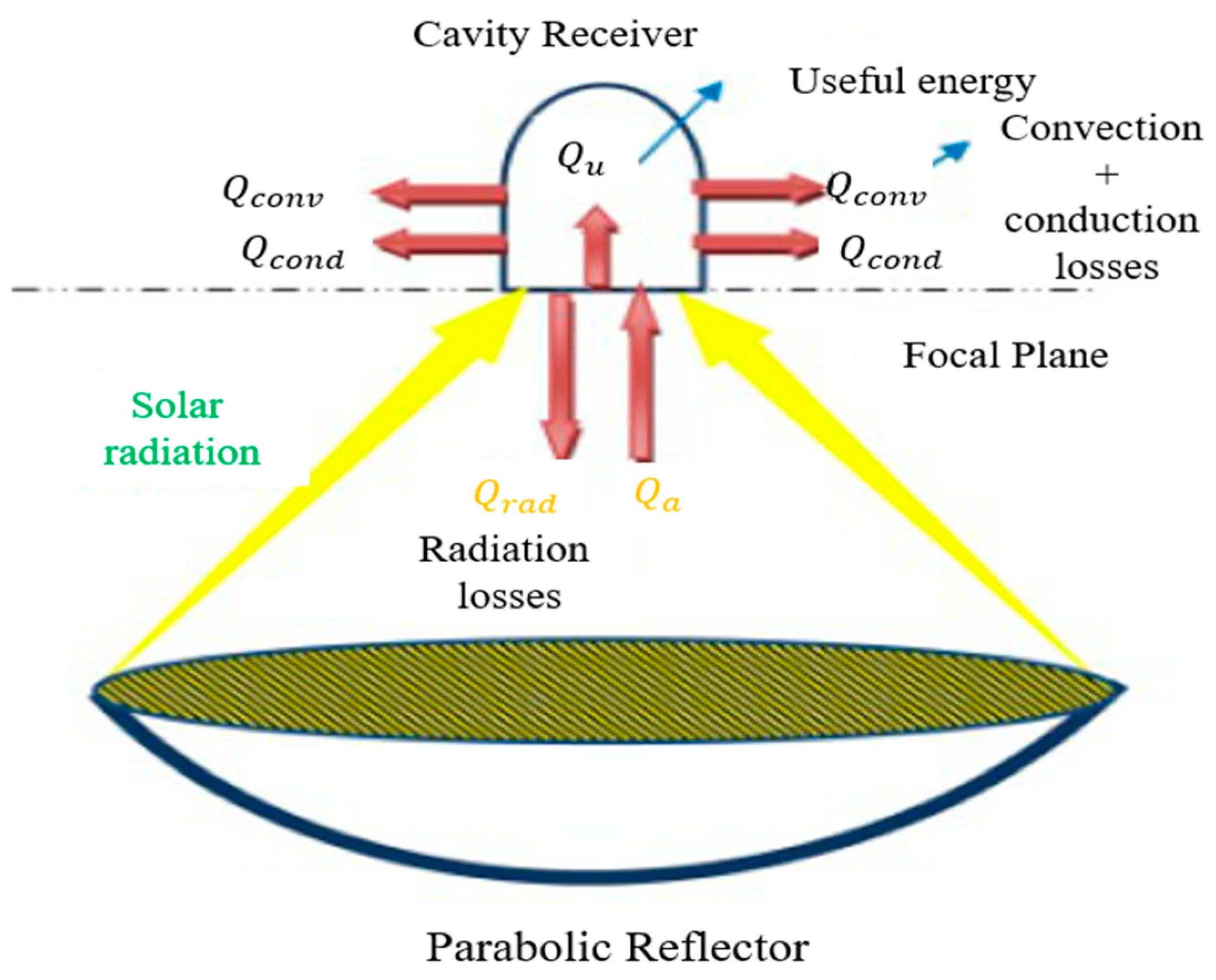
Figure 1. Receiver’s parabolic dish energy balance [34].
Energies 13 05798 g001
Figure 2. Cavity receiver grid.
Energies 13 05798 g002
Figure 3. Simulation model verification. (a) The semiempirical model of cavity receiver. (b) Temperature contours of the semiempirical model. (c) Temperature contours of the literature [39].
Energies 13 05798 g003
Figure 4. Temperature contours different cavity wall temperatures of (a) 700 K, (b) 800 K, (c) 900 K, and (d) 1000 K of inclination angle 0°.
Energies 13 05798 g004
Figure 5. The 0° inclination angle cavity receiver heat loss.
Energies 13 05798 g005
Figure 6. The 900 K temperature contours of cavity wall for inclination angle (a) 0°, (b) 30°, (c) 60°, and (d) 90°.
Energies 13 05798 g006aEnergies 13 05798 g006b
Figure 7. Heat loss of cavity wall temperature of 900 K for inclination angles 0°, 30°, 60°, and 90°.
Energies 13 05798 g007
Figure 8. The 900 K cavity wall temperature contours for different open area ratios of 0.5 and 1.
Energies 13 05798 g008
Figure 9. The 900 K cavity wall temperature contours for different open area ratio 0.25, 0.5, 0.75, and 1.3.7. Discussion.
Energies 13 05798 g009
Figure 10. Dish Stirling engine simulation block diagram.
Energies 13 05798 g010
Figure 11. Stirling engine output power and efficiency during the useful power for different wall temperature.
Energies 13 05798 g011
Figure 12. Stirling engine output power and efficiency during the s useful power for different angle.
Energies 13 05798 g012
Table 1. Theoretically calculated the average cavity temperature and wall temperature.
I DN   ( W / m 2 ) 650750850950
Q a ( W ) 135,454.485115,639.790517,725.095919,810.4013
P opt ( W ) 611705799893
T rec ( K ) 378401470524
T wall ( K ) 589645746833
Table 2. The average temperature and the wall temperature in the experiment.
Wall temperature T wall (K)7008009001000
Average temperature T r e c (K)470536598654
Δ T (K)230264302346
Q a ( W ) 14,744.15616,923.72719,359.71822,180.340
Q loss ( W ) 1412.61062409.25823844.35995831.0192
Q u ( W ) 13,331.54614,514.46915,515.35916,349.321
Table 3. Stirling engine’s output power and efficiency for different open area ratio.
Open Area Ratio0.250.50.751
Temperature (K)715675638598
Input power (W)18,494.37818,240.01017,985.63917,731.269
Output of engine (W)5587.135152.524745.244299.62
Efficiency0.3020.2820.2640.242
Ideal efficiency0.5970.5730.5490.518
Publisher’s Note: MDPI stays neutral with regard to jurisdictional claims in published maps and institutional affiliations.