1. Introduction
The irregular nature and the ever-increasing penetration of renewable energy sources in electric grids is rising the demand for more advanced, efficient and cost-effective electrical energy storage systems (EESS) [
1]. In this scenario, flywheels emerge as one of the most promising technology, thanks to their excellent compromise in terms of power and energy density, low environmental impact and long operational life [
1,
2,
3]. Apart from their historical installation in farms located in desertic or rural areas, recent trends are showing a rising interest for the installation of flywheel units in customer-side facilities, such as distribution-, smart- and micro-grids [
4,
5]. For instance, a flywheel EESS is adopted in a facility microgrid in [
6]. In [
7], M. Kermani et al. choose flywheels for the power balancing of STS-Group cranes. Finally, the use of a flywheel EESS is proposed for residential applications in [
8,
9].
For the installation in customer-side facilities, flywheel producers are called to face three main challenges:
- C1.
Follow the utmost safety standards, in a bid to mitigate the catastrophic effects of a mechanical failure [
10,
11,
12].
- C2.
Achieve high energy and power densities and high efficiency.
- C3.
Guarantee competitive capital and running costs.
In its most simple form, a flywheel is composed of a rotating disc that stores energy in kinetic form, an electric motor/generator (M/G) performing the interchange of electrical-to-mechanical energy and vice versa, and an outer vessel for both vacuum chamber and containment purposes. In order to tackle the three aforementioned challenges, flywheel producers are already focusing on several aspects, such as the design and control of the M/G [
13,
14,
15,
16], the disc’s material [
17], safety and containment [
10], or the regulation of torque and force suspensions for longer bearings’ life or bearingless solutions [
18,
19,
20]. However, not much attention is being paid to the flywheels’ architecture, which indeed has the potential for providing a key contribution in the bespoke scenario.
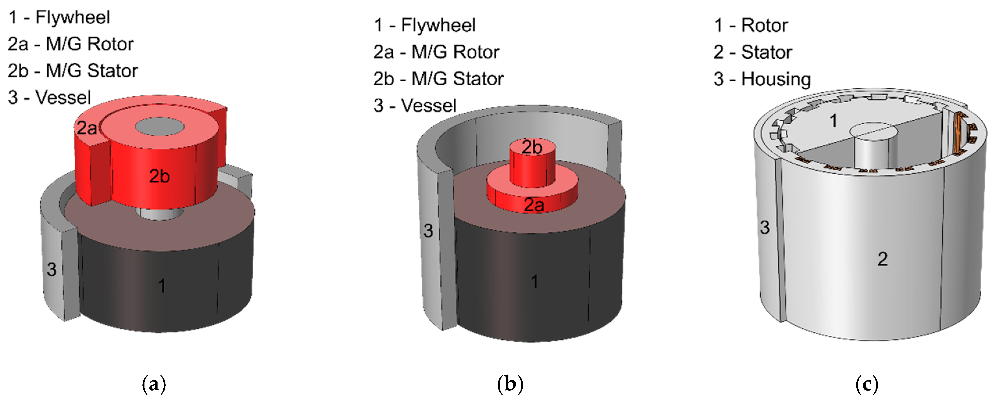
As proposed in [
21], flywheel architectures can be classified into high-speed and low-speed ones. Low-speed flywheels consist of a rotor made up of solid steel, supported by mechanical bearings and enclosed in a mild-, low- or even no-vacuum environment. The typical two-body architecture of this flywheel class is shown in
Figure 1a. Conversely, high-speed flywheels consist of a composite-material rotor, supported by magnetic bearings and enclosed in a deep-vacuum environment. High-speed flywheels are realised with either the traditional two-body architecture, or the concentric, integrated one shown in
Figure 1b. With regard to challenges C2–C3, high-speed flywheels are extremely competitive in terms of energy density. On the other hand, their high price per kWh leaves them yet to a niche market, mainly for portable applications. Per contra, low-speed flywheels are well known for being very cost effective, which makes them the preferred choice for grid-connected applications, despite their limits in energy and power density.
A possible solution for reducing the energy density issues incurred with low-speed, grid-connected flywheels may be found in the relatively unexplored one-body architecture, which is illustrated in
Figure 1c. Here, the main concept is that the rotor of an electric machine is used for both the energy storage and M/G purposes. To the best of the Authors’ knowledge, there exist only three recorded prototypes of one-body flywheels. In [
22], a homopolar machine rated for 30 kW–0.14 kWh is designed. In [
23], an axial-flux permanent-magnet machine is designed with a 30 kW and 0.08 kWh rating. Lastly, in [
24,
25], solutions for UPS systems are proposed based on an homopolar machine. The main point to note is that all contributions mentioned above adopt a solid-steel rotor, which is well-known for requiring a complex manufacturing process and a thick and bulky containment vessel.
The main idea proposed in this work is to substitute the solid rotor of a one-body flywheel with a laminated one. Indeed, as it is demonstrated in [
3,
8,
26] (in the case of a traditional two-body architecture) a laminated rotor can reduce at the same time energy density and cost by exploiting challenge C1, i.e., safety. In fact, in a laminated rotor, defects and/or cracks do not instantaneously propagate throughout the whole body, but remain confined in a relatively small region, such that only a reduced amount of stored energy is released in case of a failure. The resulting inherently higher safety level allows for a significant reduction, or even the removal of the containment vessel, which, in turn, reduces both energy density and cost.
In this work, the concepts of one-body and laminated rotor flywheel (OBOLAR-Fly), proposed, respectively, in [
22,
23,
24,
25] and [
3,
8,
26], are merged with the intention of providing a more effective response to the three challenges C1–C3 [
27]. Unlike the previous prototypes, the scheme being proposed is based on a switched reluctance (SR) machine, which has a highly different method of operation and requires a different design approach compared to [
22,
23,
24,
25]. The SR machine is chosen for its following two strengths: (1) rugged and robust rotor structure where no added features are needed, i.e., cage bars or flux barriers, in such a way as to reach the highest rotational speed for a given rotor diameter; (2) absence of a physical back-emf in idling conditions, so that the converter may be switched on during changing/discharging only, avoiding so all stand-by losses.
From the design point of view, in an OBOLAR-Fly SR machine, the key aspect is that the rotor fulfils both energy storage and electromagnetic purposes. Thus, the typical machine design aspects, e.g., power development, cooling, losses, torque ripple, etc., clash with the in-vacuum operation and moment of inertia requirements, these last being typical of a flywheel. For example, in a conventional SR machine, the rotor’s diameter and axial length are chosen mainly on electromagnetic criteria, e.g., the rated torque development, high torque-per-amp, etc. Conversely, in an OBOLAR-Fly SR machine, stored energy criteria shall be prioritised. In a similar way, an OBOLAR-Fly SR machine requires in-vacuum operation for minimising the windage loss (self-discharge). Then, the necessity of removing air from the inside of the machine alters the inner heat exchange, requiring special care during the thermal design. All the above highlights that electrical machine design and design optimisation techniques used for traditional SR machines cannot be applied for OBOLAR-Fly machines. This fact poses the further challenge of developing an effective methodology tailored for OBOLAR-Fly SR systems.
To the best of the authors’ knowledge, no prior attempts in the conceptualisation and development of an OBOLAR-Fly SR system have been recorded. Therefore, with the purpose of beginning the technological exploration of the idea, a 2.2 kWh pilot prototype has been designed, manufactured and tested. Based on all the above, the research objective is twofold:
- Obj. 1.
Provide an in-depth description of the most critical design aspects concerned with an OBOLAR-Fly SR system, and provide some useful guidelines to tackle them.
- Obj. 2.
Verify the feasibility of the idea and provide an initial assessment of the performance in comparison with the flywheels’ state of the art.
A more high-level description of the proposed OBOLAR-Fly SR system is available in [
27]. In this work, a more technical and in-depth description is provided with the support of electromagnetic and computational fluid dynamics (CFD) finite element analyses. The paper is structured as follows. In
Section 2, a high-level overview and the main design specifications of the system is provided.
Section 3 describes the main design trade-offs that characterise an OBOLAR-FLY SR system and provides some useful guidelines on how to tackle them. In
Section 4, some preliminary experimental results are provided that prove the feasibility of the idea. Finally,
Section 5 compares the performance of the OBOLAR-FLY SR prototype against current state-of-the-art flywheels commercially available. Conclusions are drawn in
Section 6.
3. OBOLAR-Fly SR System Design: Trade-Offs and Guidelines
In accordance with the Obj. 1 of this work, this section describes the most defining aspects concerned with the design of an OBOLAR-Fly SR machine and converter, along with some guidelines needed to address them. To this cause, all quantities in the analysis below are expressed in per unit, so that all the information can be extended to any other OBOLAR-Fly SR system, regardless of the power and energy ratings.
The most defining aspect of an OBOLAR-Fly SR machine is that its rotor fulfils both energy storage and electromagnetic purposes. Hence, the traditional design aspects of an electrical machine, such as power development, cooling, losses, torque ripple minimisation, etc., clash with the typical requirements of a flywheel, namely the in-vacuum operation and the moment of inertia.
Consequently, the design of an OBOLAR-Fly SR machine poses a complex problem, which is characterised by six main trade-offs:
In the next subsections, each trade-off is described more in-depth. In particular, in a bid to build up an effective design process, it is Authors’ recommendation to address the six trade-offs in the order they are listed above. A more in-depth description of the design methodology for OBOLAR-Fly SR machines will be the focus of future publications.
3.1. Rotor Material
The first and most critical design trade-off concerned with an OBOLAR-Fly SR machine is the choice of the rotor material, as it must fulfil both energy storage and electromagnetic purposes. Indeed, it is a well-known fact that the amount of energy per unit of weight that a flywheel can store depends on the material mechanical properties, namely density and tensile strength. On the other hand, a higher mechanical strength can be obtained only with poorer electromagnetic properties, which would significantly compromise losses and efficiency. Moreover, price per kg and ease of manufacturing must be considered. Therefore, the criterion that drives the choice of the rotor material is the best trade-off between tensile strength, electromagnetic properties, price per kg and ease of manufacturing.
Overall, for the rotor of an OBOLAR-Fly SR machine, there exist three different material categories that can be taken into account:
Ultra-high-strength carpentry steel.
High-strength electrical steel.
Low-strength electrical steel.
Ultra-high-strength carpentry steel is a special class of low-carbon, ultra-high-strength steel, whose metallurgic structure features a ferromagnetic behaviour. However, this class of materials is not conceived to be used in electric machinery, so that laminations thinner than 1 mm are not produced. In this work, this class of materials is taken into account by considering the Maraging C250.
High-strength electrical steel is a relatively new class of electrical steels being developed for high-speed applications, which feature a considerably higher mechanical strength compared to standard electrical steels. In representation of this class of materials, this work considers the 35HXT590T steel.
Finally, the standard electrical steel is taken into consideration through the M270-35A.
The most significant physical properties of the three materials are reported in
Table 2. By comparing the 35HXT590T and the M270-35A, it is possible to observe the anticipated degradation in terms of specific iron losses in return for a higher yield stress.
In order to solve this trade-off in a simple yet effective way, a three-step process is proposed.
The process begins with a preliminary electromagnetic sizing of the entire OBOLAR-Fly SR machine by means of analytical equations [
30], and/or FEA tools, with the objective of finding a first estimate for the rotor diameter
Dr. In this way, the electromagnetic aspects may be initially decoupled, yielding a dramatic simplification of the following steps. For the application at hand, a first estimate of 0.85 p.u. (with respect to
OD) is found for the three materials.
In the second step, a first-cut rotor geometry is obtained by combining the stored energy requirement with the mechanical stress equations. Both aspects are discussed in the following subsections.
In the final step, rotor materials that the previous step proves unfeasible may be discarded. Conversely, for those that resulted feasible, FEA electromagnetic simulations are conducted in order to assess the iron losses.
3.1.1. Stored Energy Equations
Flywheels are usually operated between a minimum, or base speed ωbase and a maximum speed ωmax, with the rated power being available within the entire speed range. The amount of stored energy E is expressed by (1), where:
E—is the energy requirement,
J—is the moment of inertia,
ωmax—is the maximum speed of rotation,
ωbase—is the minimum speed of rotation,
Dr—is the rotor outer diameter,
h—is the rotor height,
ρFE—is the rotor material density.
Then, for the purpose of finding a first-cut rotor geometry, ωbase may be set to zero, as its value is provided by the resolution of the subsequent trade-offs.
3.1.2. Mechanical Stress
In the rotors of high-speed machines, laminations are fastened onto the shaft by means of an interference fit [
31]. A 2D sketch of the main dimensions is provided in
Figure 3. Prior to being fitted and at room temperature, the shaft diameter
Dsha is bigger than the laminations’ inner hole
Di. Indeed, their difference is the interference
δint itself:
Then, the shaft is cooled down in a liquid-nitrogen bath, while rotor laminations are heated up in an oven. Once both shaft contraction and laminations expansion are complete, the two mating parts are fitted. As the parts contract back to their former size, an interfacial pressure pint is created that generates a tensile pre-stress, which impedes the mating parts’ separation. The equivalent Von-Mises stress exerted on the laminations’ bore σVM-lam is expressed by (3), being:
Dsha—the shaft diameter,
δint—the interference,
YFE—the laminations’ Young modulus,
νFE—the laminations’ Poisson modulus,
Ysha—the laminations’ Young modulus,
νsha—the laminations’ Poisson modulus.
As the rotor is spun at rotational speed ω, the laminations’ bore elongates radially much faster than the shaft. This results in a reduction of the interference and hence of the contact pressure at rising rotational speeds.
As a result, there exists a “detachment” speed
ωcrit at which the elongation equals the interference (
ur =
δint) and laminations start to “float” on the shaft:
In terms of mechanical design, two conditions must be satisfied. The first, is that the equivalent Von-Mises
σVM-lam must not exceed the laminations’ yield strength
σFE including a stress safety factor
Xσ:
The second, is that the maximum speed
ωmax shall be lower than
ωcrit including a speed safety factor
Xω:
3.1.3. Results and Discussion
By combining the equations given in
Section 3.1.1 and
Section 3.1.2, the maximum rotational speed and a first-cut rotor geometries is determined for the three materials under consideration. For the design specifications discussed in
Section 2, results are illustrated in
Table 3.
As it can be seen, the ultra-high-strength steel would be the most suitable material for what concerns the stored energy per kg (or litre). However, a critical aspect is that full material’s mechanical strength (1647 MPa) cannot be exploited. In fact, realising an interference fit that corresponds to a static stress beyond 1000 MPa, would require the laminations to be heated up beyond their thermal limit, which would compromise the lamination-to-lamination insulation. Last but not least, the price of a Maraging-C250-made rotor of 134 kg would be literally unsustainable. In conclusion, ultra-high strength steel does not represent a viable solution for OBOLAR-Fly SR machines.
For the high-strength electrical steel, the only limitation lies in the high price per kg, which is due to the fact that large material batches are not easily obtainable. Hence, as things stand at the moment, this class of material is not mature yet for an energy storage application, although it remains of very high interest for the near future.
Finally, the traditional electrical steel possesses a consolidated technology and is available at affordable prices. Hence, despite its relatively low mechanical properties, it is the only viable solution for an OBOLAR-Fly SR machine that is nowadays available.
Figure 4 shows the mechanical stress distribution caused by the interference fit at standstill in an M270-34A-made rotor.
As a result of the analysis above, for the case study at hand, the third and final step of the proposed strategy to solve this trade-off, FEA assessment of the iron losses, is not necessary. This fact yields a very important consideration: as an OBOLAR-Fly SR rotor requires a huge mass of iron to be purchased and machined; with the current state of the iron and steel technology, price per kg and manufacturability aspects dominate the choice of the rotor material, regardless of mechanical and electromagnetic properties.
3.2. Speed Ratio
As it is shown in (1), flywheel’s stored energy is inversely proportional to the square of the base speed ωbase. Hence, from the energy storage point of view, it would be desirable to set ωbase to zero.
On the other hand, it is a well-known fact that increasing the speed ratio
ωmax/ωbase, i.e., lowering
ωbase, results in higher rated torque
Trat and drive’s Volt-Ampere (VA) rating. The rated torque for a given power
Prat and
ωbase is expressed by (7), whereas the VA rating is expressed by (8), where
q is the number of switches per phase (in a standard unidirectional H-bridge topology, it results
q = 2),
m is the number of phases,
VDC is the DC-link voltage and
Irms is the phase rms current [
29]. Consequently, considering that the rated torque is proportional to
Irms squared, then the choice of
ωmax/ωbase must provide the best trade-off between stored energy and drive’s VA rating.
The resolution of this trade-off begins by a set of preliminary machine designs conducted via electromagnetic FEA to obtain the
Irms needed for each value of
ωbase. Subsequently, the power converter is simulated via software, the objective of the simulations being the development of the drive’s VA rating as a function of the speed ratio. For the design specifications given in
Table 1, the plot is shown in
Figure 5a, where the VA rating is expressed in per unit (p.u.) with respect to the rated power. It is observed that the curve remains almost unvaried for different number of phases, since the product
m VDC Irms is practically constant for a given power rating. Besides,
Figure 5b illustrates the variation of the stored energy at different speed ratios. Stored energy is expressed in percent with respect to the ideal case where
ωbase is equal to zero.
By analysing the plots, an optimal speed ratio may be taken at 5. In this way, only 4% of the storage capacity is lost compared to the ideal case where
ωbase = 0, in return for a reasonable converter VA rating, i.e., around 15 p.u. The resulting energy vs. speed and power vs. speed characteristics are illustrated in
Figure 6.
3.3. Number of Phases
At this point, as the speed ratio and the rated torque have been set, the choice of a transformer-less connection along with the torque ripple limitation drives the choice of the number of drive phases m.
For each possible number of phases, by considering the preliminary SR machine and converter designs conducted during the resolution of the previous trade-off and by bearing in mind that the product m VDC Irms is practically constant, the voltage level for each value of m can be obtained.
For the application at hand, the values of voltage and current levels as functions of
m are reported in
Table 4. Here, given that a transformer-less AFE connection constraints the DC-link voltage within 600–900 V, SR systems with less than three and more than 9 phases must be discarded.
Once the unfeasible number of phases have been discarded, the choice of
m continues by considering the torque ripple constraint. Several studies demonstrate that the torque ripple tends to reduce as the number of phases increases [
32]. Therefore, based on the design principle of keeping the system’s complexity at its lowest, the trade-off here is to keep the minimum value of
m that is sufficient to meet the torque ripple constraint. For the case study at hand, an eight-phase drive is selected. The resulting torque vs. rotor position loci at both base and maximum speed are shown in
Figure 7.
3.4. Split Ratio
A schematic representation of the stator geometry is provided in
Figure 8. The term “split ratio” denotes the ratio between the stator bore diameter
Ds and the machine outer diameter
OD. As it is shown in (1),
Ds is the key geometrical parameter that defines the energy storage capacity (as the airgap length is negligible, then
Ds ≅
Dr). Hence, in a bid to maximise the stored energy and so the energy density, the split ratio is also to be maximised or, in other terms, the space occupied by the stator is to be minimised.
As it is shown in
Figure 8, the stator volume is defined by the stator tooth height
hst and the stator yoke thickness
bsy. Hence, FEA simulations have to be conducted in order to size
hst on the merit of minimum iron loss.
Figure 9a shows the quadratic trend of the iron losses vs.
bsy, in the case of the prototype at hand. Here, losses are expressed in per-unit with respect to the rated power, whereas
bsy is given in per-unit with respect to
OD. A value of approximately 0.055 p.u. may be taken, as a greater value would not result in a significant loss reduction.
With regard to
hst, its value is chosen in order to have sufficient space for the copper’s conductors that develop the rated torque
Trat, without exceeding the current density limitation of 4 A/mm
2 (see
Section 2). For the application under consideration,
Figure 9b shows the values of current density needed for developing
Trat for different values of
hst. This last is expressed in per-unit with respect to
OD. Consequently,
hst may be taken around 0.025 p.u.
3.5. Optimal Vacuum Level
A further key design trade-off involved in OBOLAR-Fly SR machines is the choice of the vacuum level. Flywheels are usually operated in a high-vacuum environment, in a bid to minimise the windage losses, i.e., the self-discharge. On the other hand, as the rotor fulfils both electromagnetic and energy storage purposes, maintenance of a high vacuum yields the technological challenge of cooling the machine. In fact, the air contained inside the machine has the function of cooling it down. As the vacuum level is increased, the internal convective cooling tends to disappear, so that temperatures tend to increase. A trade-off is therefore necessary to minimise the windage losses whilst keeping the machine’s temperatures within their permitted values.
To evaluate this trade-off, Computational Fluid Dynamics (CFD) simulations must be combined with thermal analysis tools, i.e., a lumped-parameter-thermal network [
33,
34], or Finite Element simulations. The objective is to assess windage losses and machine’s temperatures at different vacuum levels. In the case of the prototype at hand,
Figure 10a shows the windage losses vs. vacuum pressure locus, with losses being expressed in per-unit with respect to the rated power.
Figure 10b illustrates the end-winding and rotor temperatures at different vacuum levels. As it can be seen, a very good trade-off is found with a mid-vacuum level of 10
−3 mbar, where the windage loss is less than 0.1% of the rated power and the end-wing temperature remains below 200 °C.
3.6. Controller Hysteresis Band
With regard to the design of the power electronics, the first objective is the maximisation of the roundtrip efficiency, while complying with the restrictions resulting from the controller’s hysteresis band. This last shall be selected in a bid to optimise the balance between control bandwidth, semiconductor losses and the SR drive performance.
In SR drives operating in wide constant power speed ranges, such as an OBOLAR-Fly, two different control strategies are necessary at different speeds. At relatively low speeds, SR drives are normally operated in current control, or chopping mode. Here, a hysteresis controller is commonly adopted to keep the phase current within a specified “hysteresis band”, as it is shown in
Figure 11. Conversely, at high speeds, the high machine’s pseudo back-emf prevents the phase current from reaching the hysteresis threshold, resulting in the so-called “single pulse” mode, with each phase being turned on and off only once per cycle [
35]. As a result, the high number of switching instances per period causes an SR drive to have its highest semiconductor losses at low speeds. For this reason, operation at
ωbase is taken into account for the choice of the hysteresis band.
In the case of a wide hysteresis band, the maximum phase current rises. This, in turn, produces a higher peak current stress, together with a higher torque ripple. Per contra, with a narrower hysteresis band, a higher number of switching instances per period are necessary, which results in excessive bandwidth/sampling rates requirements and/or switching losses.
For tackling this trade-off, an iterative process of SR machine and converter co-simulations is necessary. This process involves the choice of the modulation strategy as well, i.e., hard switching or soft switching [
36]. Under hard switching, both switches of the same leg (see
Figure 2b) are turned on/off simultaneously so that the phase voltage alternates between ±
VDC. Under soft switching, switches are controlled independently, changing the phase voltage between +
VDC and 0 V. This, in turn, reduces the rate of current decay within the hysteresis band and so does the number of switching instances per period. For the application at hand, based on the design specifications given in
Section 3.1., a ±10 A hysteresis band is chosen with a soft switching strategy. This choice reduces the number of switching instances within one period, even though more hardware/software implementation efforts are needed. Switching losses at both maximum and base speed are reported in
Table 5.
3.7. Converter Design Finalisation
For the sake of completeness, this subsection gathers some final guidelines about the finalisation of the power electronics design. Further to DC-link voltage and hysteresis band previously chosen, together with the power and rms current ratings, semiconductors’ modules may be chosen on the merit of the lowest converter losses. For the application at hand, the Infineon IGBT modules DF200R12PT4_B6 and FD200R12PT4_B6 (200 Arms/1200 V) have been selected for the top and bottom switches, respectively.
Then, the semiconductor losses are used for sizing the heatsink. The thermal resistance requirement is evaluated in such a way as to guarantee that the semiconductor junction temperature does not exceed its maximum values. For the prototype being described, a forced air-cooled heatsink has been designed, which provides a 0.04 W/C thermal resistance. The choice of an air-cooling system over a liquid-based solution, is in-line with the principle of keeping the system’s cost and complexity at their minimum.
The final design point is concerned with the DC-link capacitance CDC. Its choice is made in a bid to minimise the voltage dip incurred in a power step, i.e., a power reversal. For the prototype being considered, an oversized capacitance of 4.4 mF has been chosen.
The final converter packaging is shown in
Figure 12. Authors wish to highlight that this layout has been developed for the purposes of a pilot prototype. Therefore, practical aspects such as ease of repair, re-configurability, versatility, etc. have been prioritised. For future designs, a more compact layout can be easily obtained.
4. Preliminary Experimental Results
Based on the guidelines and the resolution of the six trade-offs discussed in
Section 3, a physical prototype of OBOLAR-Fly SR system has been manufactured and tested. This section provides an overview on some preliminary experimental results, with the intention of assessing the feasibility of the OBOLAR-Fly idea.
For the flywheel testing, a special high-safety testing chamber has been set up, which is shown in
Figure 13. Here, the arrangement of the main components can be observed: the OBOLAR-Fly SR machine fastened to the concrete floor, the power converter, the control board, the vacuum pump, the measurement equipment, along with the users’ PC and instrumentation.
Figure 14a shows the static inductance vs. rotor position profiles obtained via FEA (blue curve) and experimentally with an N4L-PSM1735-IAI impedance analyser (grey dots). In the plot, a very good agreement between FEA and experimental results can be observed. Moreover, a saliency ratio—ratio between maximum and minimum inductance—of 4.6 can be seen.
Figure 14b, shows the phase current vs. rotor position waveform at 1120 rpm. The ±10 A hysteresis band can be seen. In this case, the discrepancy between the simulated and experimental waveforms is caused by the discrepancy between the FEA and experimental inductance values, as well as the switching delay.
Finally, a set of three 10-min deceleration curves is shown in
Figure 14c. In Curve 1, a deceleration from 4200 rpm in a mild-vacuum environment (0.1 bar) is shown. Here, the average friction loss may be obtained by post-processing the data. Friction loss results of approximately 2.7 kW. Curves 2 and 3 are obtained under a normal- and mild-vacuum environment respectively. A considerable improvement in the rate of speed decrease and hence stored energy be seen. In terms of lost energy, curve 2 shows that 28% of the total state of charge (SOC) is lost in 10 min, whereas curve 3 proves that only 9% of the SOC is lost in a mild-vacuum environment. However, based on the CFD analysis conducted in
Figure 1, the SOC loss is expected to be reduced of around two orders of magnitude in mid-vacuum operation.
The experimental testing has also helped to highlight two further critical aspects to address in future research works. Firstly, mechanical vibrations remain a considerable issue, despite the strict limitation posed on the torque ripple. Indeed, unbalanced radial forces provide a further source of vibrations [
23], which must be considered more in-depth in future designs, along with torque-ripple-cancellation controls. Secondly, vacuum operation proved to be another critical aspect of an OBOLAR-Fly SR system, so that an advanced sealing technology for the housing and an accurate vacuum pump control system will be necessary for future test beds.
5. Performance Assessment and Final Considerations
Following from the Obj. 2 of this work, the performance of the proposed OBOLAR-Fly SR system is now compared against current state-of-the-art flywheels.
The efficiency of some commercial flywheel models is reported in
Table 6. The comparison of these values against those reported in
Table 5, demonstrates that, in terms of efficiency, the proposed OBOLAR-Fly SR system is perfectly in line with the current state of the art.
With regard to the power and energy densities, a comparison is conducted in
Figure 15. Here, the OBOLOAR-Fly #1 indicates the prototype discussed in the previous sections. As it can be seen, the proposed solution is extremely competitive in terms of power density. This is due to the fact that the stator outer surface almost equals that of the chassis, which provides an extensive surface available for heat extraction. On the other hand, the low energy density is caused by the poor mechanical properties of the conventional electrical steel. As a term of comparison, the OBOLOAR-Fly #2 is included in the plot. In this case, the 35HXT590T steel (see
Table 3) is considered as rotor material for the same prototype’s geometry. As it can be noted, the stronger rotor material allows the OBOLAR-FLY SR system to be more than competitive also in terms of energy density. This fact confirms that the rotor material is the most critical aspect in the development of OBOLAR-Fly SR systems.
All the above concludes that the concept of OBOLAR-FLY SR system is feasible. Its main advantages and disadvantages can be summarised as follows.
Despite the prospected improvement in energy density shown in
Figure 15, the proposed OBOLAR-Fly SR system is not expected to be competitive against the energy density of chemical batteries. On the other hand, it offers significant advantages where short-term, high-power ratings are necessary, such as ancillary services, frequency correction and power conditioning. Moreover, OBOLAR systems may deliver a very cost-effective solution, which can operate in harsh environments, where conventional storages might be significantly de-rated. The final foreseen advantages are the long lifetime with little, or even no de-rating over time, as well as the straightforward recyclability of all its structural and active materials.
In terms of disadvantages, the gap with existing flywheel models is mainly caused by: (1) the considerable amount of vibrations, which might require flexible or damping mountings and/or foundations for future prototypes, (2) performance is highly dependent on the rotor material. With regard to this, it is undoubted that the market demand for high-speed electrical machines is constantly rising [
37], and cost issues related to high-strength electrical steel are expected to be mitigated in a relatively low time. Based on this, it is authors’ opinion that it is worthwhile to move further with the investigation, considering the 35HXT590T steel (or similar) from the very beginning.

 ,
, 


