Article

Optimization of Return Channels of High Flow Rate Centrifugal Compressor Stages Using CFD Methods

1
National Technological Initiative Center of Excellence in New Manufacturing Technologies, Peter the Great St.Petersburg Polytechnic University, 195251 Saint-Petersburg, Russia
2
Higher School of Power Engineering, Institute of Energy, Peter the Great St.Petersburg Polytechnic University, 195251 Saint-Petersburg, Russia
3
Higher School of Hydrotechnical and Power Engineering, Institute of Civil Engineering, Peter the Great St.Petersburg Polytechnic University, 195251 Saint-Petersburg, Russia
*
Author to whom correspondence should be addressed.
Energies 2020, 13(22), 5968; https://doi.org/10.3390/en13225968
Submission received: 6 October 2020 / Revised: 11 November 2020 / Accepted: 11 November 2020 / Published: 16 November 2020

Abstract

:
Calculations performed with modern CFD programs aid in optimizing flow paths of centrifugal compressors. Characteristics of stator elements of flow paths, calculated via CFD methods, are considered quite accurate. We present optimized return channels (RCh) of three model industrial compressor stages with vaneless diffusers. A parameterized model was created for optimization. The MOGA (Multi-Objective Genetic Algorithm) optimization method was applied in the Direct Optimization program of the ANSYS (Analysis System) software package. Optimization objects were return channels of the stages with high flow rate 0.15. The stages have three different loading factors 0.45, 0.60, 0.70. The optimization goal was to achieve the minimum loss coefficient at the design point. During the optimization process, we varied the following: the number of vanes, the inlet angle of the vanes, the height of the vanes at the inlet, the outer and inner radii of curvature of the U-bend. The outlet angle of the vanes was selected to minimize outlet circumferential velocity. In comparison with preliminary design, the optimized RCh are more efficient across the entire range of flow rates. The optimization reduced the loss coefficient by 20% at the design flow rate.

1. Introduction

The Universal Modeling Method was developed at the Peter the Great St.Petersburg Polytechnic University, Saint-Petersburg, Russia (SPbPU) for gas-dynamic design and calculation of characteristics of industrial centrifugal compressors and has been actively used to fill the needs of compressor manufacturers since 1990th. More than 400 compressors with unit capacities of up to 25,000 kW and a total capacity of approximately 5.5 million kW were delivered to end users [1,2]. This complex of computer programs is based on the algebraic models of the work coefficient and efficiency [3,4]. Identification of these models is based on the results of experimental and computational studies and is constantly being improved as data accumulates.
The first design phase is the preliminary design. The Universal Modeling Method treats a design flow rate coefficient Φ d e s = 4 m ¯ / ρ i n l π D 2 2 u 2 and a design loading factor ψ T d e s = c u 2 / u 2 as two main parameters for a stage design. The complete theory is presented in the monograph [5]. In order to bring the preliminary design closer to the optimal solution, a number of studies of impellers and vaneless diffusers were carried out using the methods of mathematical modeling, CFD (Computational Fluid Dynamics) and Q3D (Quasi-three-dimensional) calculations [6,7,8,9]. Return channels are less studied and have attracted attention of researchers and engineers last several years. Return channels are objects of numerical and experimental research. Papers and reports [10,11,12,13,14,15,16,17,18,19] provide information on the problem. The authors of [10,11] have at their disposal the powerful rig to test high flow rate intermediate type stages. In [10] the authors have proven characteristics of the stage with CFD-optimized return channel by experiment. The agreement between the calculated and measured characteristics should be considered quite satisfactory. The calculated internal head is only 2–3% higher. To the contrary, in [20,21,22,23,24,25], a discrepancy between the head coefficients was to 12%, and a large discrepancy between the optimal and critical flow rates were obtained.
The authors of [12] compared calculated and tested characteristics of the stage with a return channel of original design. The splitter vanes improved stage characteristics at Φ > Φ d e s . The model stage was provided with an imitation of the preceded return channel.
The authors of [13] by CFD optimization of return channels (RCh) increased the efficiency of a two-stage compressor by 0.7% (experimental confirmation). In [22] many parameters of one return channel are optimized together with a vaneless diffuser.
Papers [14,15] focus on RCh with “integral” vanes that are extended from the RCh into a U-bend and into a vaneless diffuser.
Paper [16] presents minimization of non-uniformity of the flow at the outlet from the RCh by selecting the inclination of the trailing edge of the vanes. The authors of [17] focus on taking into account the flow of leaks at the outlet of the RCh through the labyrinth shaft seal. The papers [18,19] are dedicated to optimization of the U-bend and 3D vanes.
The merit of the quoted above papers is that CFD-optimization positive results were proven by experiments. However, in known publications, the task of optimizing a large number of RCh for stages in a practically significant range of design parameters was not posed.
The ultimate goal of the authors of this article is a systematic CFD study of return channels in order to improve methods of the preliminary design. Some steps in this direction have been taken [20,25]. The preliminary design algorithm now can be applied in the range of parameters Φ d e s = 0.015−0.15 and ψ T d e s = 0.45−0.70. The series of stages will be designed in this range of design parameters. The designed RCh will be CFD-optimized. The generalized results will be introduced in the design algorithm. In this paper the sample of this procedure is presented. Three stages with the same flow coefficient 0.15 and three loading factors 0.45, 0.60 and 0.70 are the objects of the research.
In the modern version of the Universal Modeling Method, the preliminary design of RChis based on recommendations of classic monographs in Russian [5,26,27,28,29] and English [30,31]. Figure 1 shows the main dimensions of the RCh after the preliminary design.
The design parameter of the RCh is the flow inlet angle α 4 d e s that corresponds to a stage design parameter Φ d e s . The goal of the optimization is to minimize the loss coefficient at the design regime.
Meridional dimensions of a RCh by the Method design are the next. Circular arcs and straight lines form the meridional configuration.
The dimensions of the outlet D ¯ 0 , D ¯ h are determined by the dimensions of the impeller of the next stage. The outlet dimensions cannot be optimized. This way determined parameters are design constrains and are not subjects of optimization.
The book [5] contains recommendations on the choice of dimensions R ¯ s 6 , R ¯ h 6 , D ¯ 6 , b ¯ 6 , ( R is a radius, b is a vane height) proven by design practice.
The important parameter for optimizing the meridional shape is the height of the vanes b ¯ 5 . For a given angle α 4 d e s and the vaneless diffuser’s width b ¯ 4 , the value b ¯ 5 determines the flow inlet angle α 5 of the vanes. The ratio b ¯ 5 / b ¯ 4 determines the flow conditions in the U-bend.
An axial dimension L ¯ u b determines the friction loss in the U-bend.
The radii R ¯ s , R ¯ h also determine the friction loss in the U-bend and the local velocity gradients.
Radial dimensions of a RCh by the Universal Modelling Method design are the next.
The inlet vane angle α v 5 is the subject of optimization to ensure a favorable flow inlet at the design flow rate.
The vane outlet angle α v 6 should provide the outlet flow angle α 0 = 90 0 .
The number of vanes should be optimized to minimize the sum of friction and separation losses.
The shape of the profile and the shape of the centerline can be optimized to minimize the loss coefficient.
Some experiments and CFD calculations have demonstrated good flow conditions in channels with vanes formed by circular arcs. The 2D vanes of this type were chosen as the object of research and optimization. Double-arc profiles are used in the initial design and are not optimized.
Shape parameters of a double-arc profile that were not optimized:
-
Maximum thickness δ ¯ max .
-
Leading edge radius R ¯ L E .
-
Trailing edge radius R ¯ T E .
Parameters δ ¯ max and R ¯ L E were studied in [20]. The test results and CFD calculations of the model stage with Φ d e s = 0.028 are presented. Figure 2 shows the characteristics of the stator part loss coefficient according to the preliminary design, and after optimization of b ¯ 5 , z (number of vanes), α v 5 , R ¯ L E , δ ¯ max .
For the flow rates ranging between design and surge ones, the preliminary design is not inferior to the optimized RCh. The advantage of the optimized RCh starts in the high flow rate area at Φ / Φ d e s > 1.15. Industrial compressors are not used at high flow rates where pressure ratio and efficiency are low. Attention is drawn to the fact that at the design Φ d e s = 0.028 the loss coefficient is minimal. For this stage the preliminary design is effective enough. In this article, the authors present the results of optimization of the RCh of three high flow rate stages with Φ d e s = 0.15. For high flow rate stages, the optimization can yield a more significant result.

2. Materials and Methods

Three stages with the parameters Φ d e s = 0.15, ψ T d e s = 0.45, 0.60, 0.70 were the subjects of the preliminary design according to [9,32]. The return channels of these stages are initial versions to be optimized. The parameters of optimization were number of vanes z , vanes’ relative height b ¯ 5 and vane inlet angle α v 5 .
The preliminary design is carried out using the PDCC-G8E PC software (Peter the Great St.Petersburg Polytechnic University, Saint-Petersburg, Russia) for variant calculation and preliminary design, Figure 3.
In the Universal Modeling Method, the flow path of the stage is determined by two coefficients, Φ d e s and ψ T d e s . The main design limitation is the hub ratio D ¯ h . The program performing variant calculation evaluates the efficiency of stages according to a simplified model [33], modernized by the authors [34,35,36]. Table 1 presents the main parameters of the selected compressor variant, obtained using the PDCC-G8E PC software.
Several algebraic equations solve the efficiency as η = f ( Φ d e s , ψ T   d e s , D ¯ h , M u ) . The program PDCC-G8E calculates the dimensions of the flow path and presents them in tabular and graphical forms, Figure 4.
Table 2 shows the dimensions of the return channels of the stages with Φ d e s = 0.15 and ψ T d e s = 0.45, 0.60 and 0.70 according to the preliminary design. The last line indicates the Φ c r value at which the maximum pressure ratio is reached. In engineering calculations, this flow rate is considered to be the surge boundary [37]. The calculation was made according to the method of preliminary design [7,38].
The authors have studied this problem in [39,40]. The object of the research there was a return channel as well. The computational domain includes a vaneless diffuser. One of the main principles of the Universal Modeling Method is the summation of head losses calculated in individual elements of the stage. The mathematical model of vaneless diffuser was created by the author of [41] and was included in the programs of the Universal Modeling Method [3,42]. In order not to calculate the head loss in the vaneless diffuser again, the condition “free slip” was set for the vaneless diffuser’s walls. Figure 5 shows a comparison of the flow structure of two variants with “free slip” and “no slip” walls of the vaneless diffuser (the stage with Φ d e s = 0.028).
The preliminary design establishes such value of vaneless diffuser relative width that guarantee no-separation flow angle at a surge limit. Flow cannot be separated at a design flow rate therefore. There are no visible differences in the flow structure. With “free slip” walls of the vaneless diffuser, the flow is slightly more orderly. The length of the outlet section is chosen to be the minimum, at which the flow is close to being uniform at the outlet. Figure 6 shows a scheme of the outlet section.
The return channel of the stage with Φ d e s = 0.028 was calculated for three lengths L 1 = R h 6 , L 1 = 3 R h 6 Φ L 2 = 6 R h 6 . The flow structure of the calculated variants is shown in Figure 7.
Even at a large distance from the “0′” section (Figure 7, right), the flow does not become completely uniform. In the meridional plane, the flow becomes uniform even at a distance L 1 = R h 6 . A smaller distance also allows us to reduce the size of the computational grid and, accordingly, reduce the time spent on calculations. The boundary condition “free slip” is set on the walls, so that the flow does not stick to the pipe walls, and the pipe length does not affect the losses in the RCh.
The effect of splitter vanes was studied using the example of a stage with Φ d e s = 0.28. Figure 8 shows the flow structure in return channels with and without splitter vanes.
The outlet flow angle with a splitter vane is 88.60° versus 82.70° when splitter vanes are absent. The splitter vanes are necessary for the efficient operation of return channels.
Two candidates of the return channel of the stage with Φ d e s = 0.15 were compared. Normally, the splitter vanes are installed after each second vane. This variant had splitter vanes after each vane. Figure 9 shows the structure of the flow in these versions of the return channel. The doubled number of splitter vanes led to a significant increase of the loss coefficient.
Based on the results of calculations in [39,40], the following calculation technique was chosen:
-
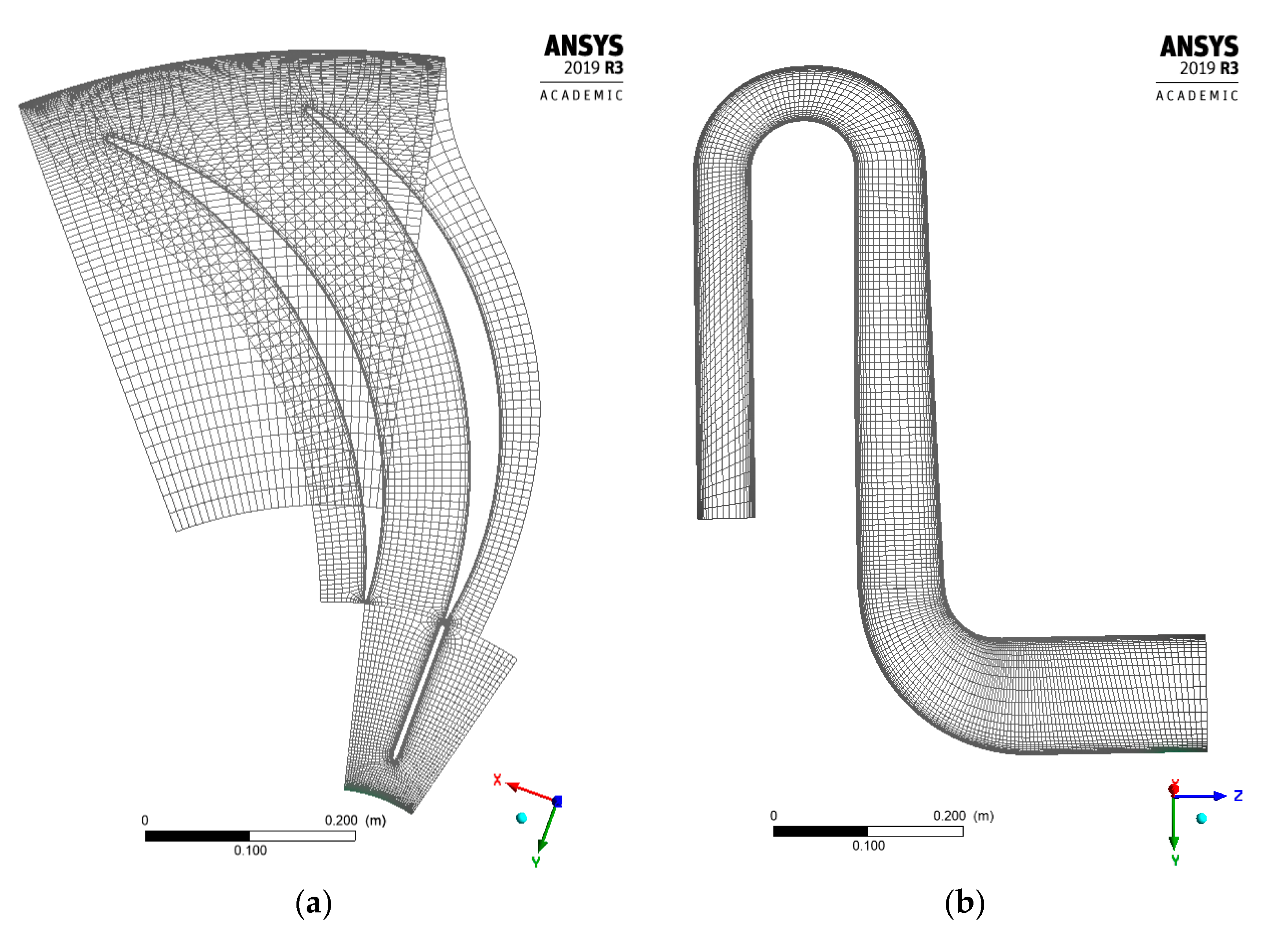
In the grid generator TurboGrid (ANSYS 2019 R3, ANSYS Inc., Canonsburg, PA, USA ), computational grids were built separately for vanes and splitter vanes. The total number of elements was 398,000.
-
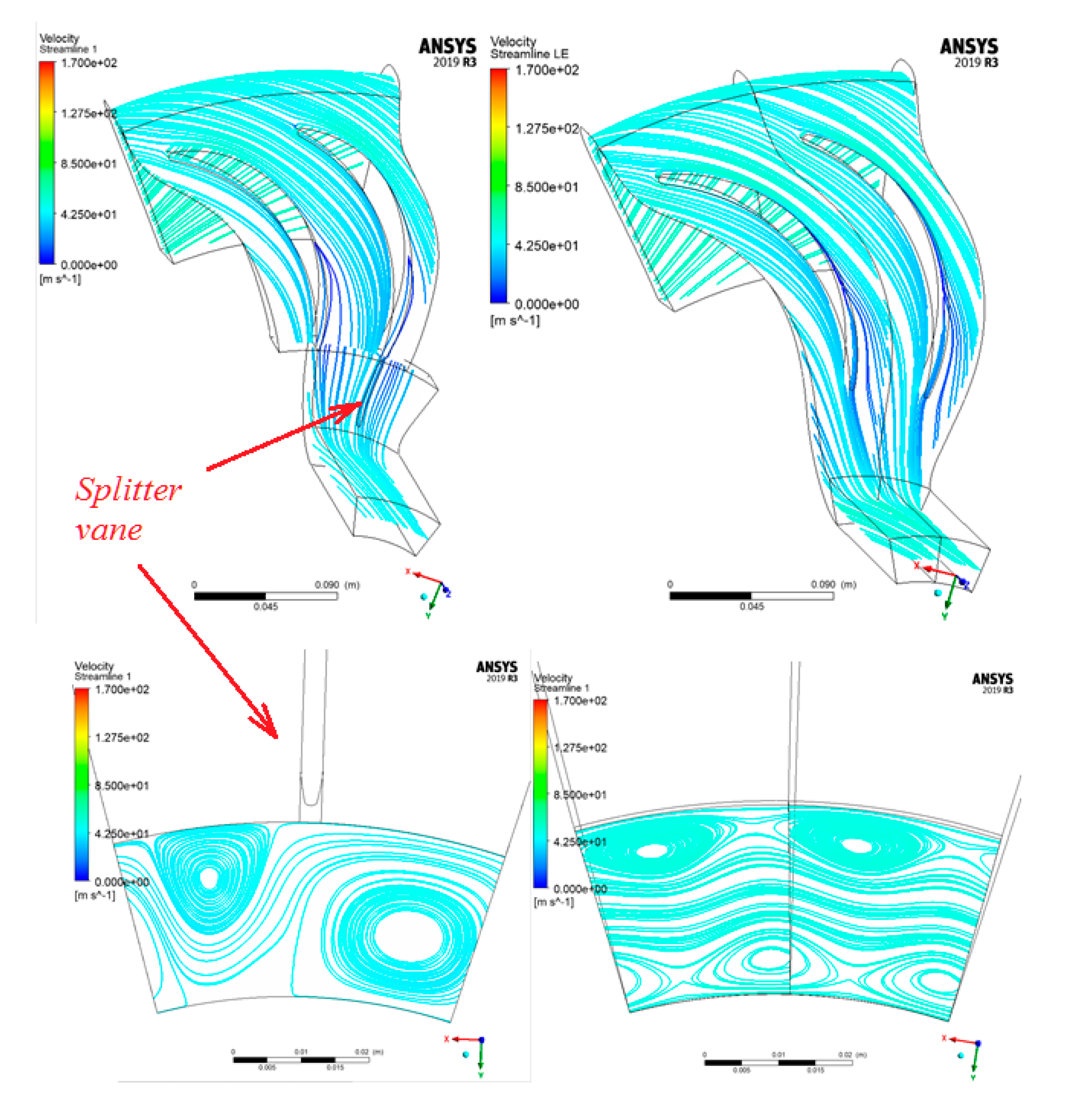
In the CFX-Pre program, the computational grids were combined into one area, consisting of two vanes and one splitter vane (Figure 10).
-
The values y+ < 2 (dimensionless height of the first boundary element) in 98% of the bounding surfaces’ area. In several problematic areas (about 2%), y+ values reached 20. In both cases this values meet the requirements of correct modeling of the boundary layer using the SST (Shear-Stress-Transport) turbulence model.
-
Total pressure p 2 * , total temperature T 2 * and a flow angle α 3 were set at the inlet.
-
The mass flow rate m ¯ was set at the outlet.
In the Direct Optimization program, the formula for calculating the loss coefficient is set as an objective function for optimization:
ζ 4 0 = p 4 * p 0 * 0.5 ( ρ 4 ρ 0 ) 2 c 4 2
Here p 4 * ,   ρ 4 ,   c 4 are total pressure, gas density and flow velocity at the RCh inlet, p 0 * , ρ 0 are total pressure and flow density at the RCh outlet. The Direct Optimization program (ANSYS 2019 R3, ANSYS Inc., Canonsburg, PA, USA) allows to select an optimization method that depends on the number of goals, on the constraints set, and on the desired number of design points. The MOGA method was used for optimization [43,44,45].

3. Results

3.1. Return Channel Variants of the Stages with a flow rate of 0.15, a Loading Factor of 0.45

For the initial RCh, according to the preliminary design, the flow exit angle is 88.70° (ideally, 90°) at the design flow rate coefficient Φ d e s = 0.15, and changes little at other flow rates. In this respect, the preliminary design can be considered satisfactory. However, unlike the preliminary design of the low flow rate stage in the Figure 2 [20], the minimal loss coefficient does not correspond to Φ d e s . The preliminary design formulae should be corrected towards an increase of the inlet area of vane channels.
The number of vanes can be represented with the gas dynamic criterion a dimensionless vane load. The criterion Δ c ˜ a v is the difference between the velocities on suction and pressure vane sides, averaged over the length of the vane, referred to the velocity at the inlet to the cascade Δ c ˜ a v = ( c s c p r ) a v / c 5 . The formula follows from the momentum equation: [5]:
Δ c ˜ a v 2 π z 8 sin α 5 · cos α 5 ( 1 + b 6 / b 5 ) [ 1 ( D 6 / D 5 ) 2 ] ( 1 + b 5 b 6 D 5 D 6 sin α 5 )
Figure 11 shows normalized loss coefficient of optimal RCh variants with different z / z O R G , b 5 / b 5 O R G and their vane load. A loss coefficient at the design flow rate of the return channel by the preliminary design is ζ d e s   O R G . A loss coefficient at the design flow rate of any other return channel candidate is ζ d e s . A subscript «ORG» stands for Original, i.e., related to a return channel dimensions after a preliminary design.
The Direct Optimization program using MOGA algorithm searched an optimal even number of vanes at four vane inlet heights b 5 = b 5 O R G , b 5 = 1.1   b 5 O R G , b 5 = 1.2   b 5 O R G , b 5 = 1.35   b 5 O R G . Unexpectedly the optimal vane height is higher, and vane number is sufficiently less than of the RCh after a preliminary design.
The minimal loss coefficient was achieved for return channels with b ¯ 5 O P T = 1.2   b ¯ 5 O R G and b ¯ 5 O P T = 1.35   b ¯ 5 O R G . For further analysis, variants with b ¯ 5 O P T = 1.2   b ¯ 5 O R G are chosen.
The number of vanes of the RCh with minimal loss coefficient turned out to be unexpectedly small: z / z O R G = 0.46, Δ c ˜ a v = 0.44. Little number of vanes means higher vane load—Equation (2). Higher maximum velocity can result in local flow deceleration and flow separation. Separation zone and mixing losses in a RCh outlet are undesirable. Figure 12 shows the vane load as a function of the flow coefficient for RCh variants with b ¯ 5 O P T = 1.2   b ¯ 5 O R G and different numbers of vanes.
But the load Δ c ˜ a v = 0.44 at a design flow coefficient appeared to be not unappropriated for the return channel under investigation. Vane pressure diagrams in the Figure 13 clarifies the problem.
The number of vanes is even in all RCh variants. Splitter vanes are installed after every second vane. The diagrams show two adjacent vanes, with and without splitter vanes. In both cases, the pressure decreases on the surfaces of the vanes. That is, the flow is accelerated without a tendency to separation. Figure 14 shows the streamlines in the RCh with z / z O R G = 0.54 on three vane-to-vane surfaces.
The incidence is positive near the diaphragm in the Figure 14 (left). It leads to local separation. However, in most of the channel, the flow is continuous, despite the low vane cascade density. As a preliminary design, this return channel is satisfactory. In a course of a final optimization in an U-bend of better configuration a separation zone could be diminished. 3-D vanes with different vane inlet angles along a leading edge could be more effective.
With a low-density vane cascade, there is a concern that flow structure may be unsatisfactory at the RCh outlet. Figure 15 shows the field of the circumferential component of the velocity at the exit from the return channels with different numbers of vanes.
At z = z O R G , the maximum difference is c u max c u min = 32.4 m/s ( c u is a circumferential velocity). At z = 0.69 z O R G , the maximum difference is c u max c u min = 34.4 m/s. At z = 0.54 z O R G , the maximum difference is c u max c u min = 36.5 m/s. The difference seems not to be significant. For candidates with all possible numbers of vanes the minimum circumferential velocity is negative: c u min < 0. Obviously, the non-uniformity of the flow cannot be an obstacle to using a RCh with a small number of vanes. However, the problem could arise at flow rates Φ < Φ d e s .
Figure 16 shows the outlet flow angle for a number of RCh variants at different Φ .
The characteristics α 0 = f ( Φ ) for the variants with vane outlet angle after the preliminary design α v 6   O R G are located a little below the 90° line. The outlet flow angle for the variant with z   =   z O R G is 88–89° throughout the entire range of Φ . The outlet flow angle of RCh variants with z < z O R G is smaller, up to 86.5°, in the range Φ Φ d e s . We have made calculations for variants with z = z O R G and splitter vanes installed after each vane. This does not help and simultaneously increases the loss coefficient.
As an alternative solution to this problem, the RCh vane outlet angle can be increased α v 6   > α v 6   O R G . Two variants with increased α v 6 are shown on the Figure 16. For these variants, the outlet flow angle is 90° at Φ d e s = 0.15. However, at Φ < Φ d e s the angle exceeds 90°, and the flow acquires a negative swirl. This additionally increases the incidence angle at the inlet to the next stage impeller, which is undesirable.
The authors believe that the recommended by the preliminary design vane outlet angle is acceptable. The question of the number of vanes should be resolved taking into account the operation of the RCh at low flow rates. Figure 17 shows the characteristics of the loss coefficient of the return channel after the preliminary design and of the optimized variants with different numbers of vanes.
The variants with a small number of vanes are effective at Φ d e s but operate unsatisfactorily at small flow rates. The loss coefficient increases strongly at Φ < 0.105. Return channels with a small number of vanes should not be recommended for practical use. The authors believe that an acceptable compromise is the RCh with z / z O R G = 0.69. In the design flow rate its loss coefficient is 21.5% less than of the return channel after preliminary design. The recommended variants’ vane average load is 0.325.

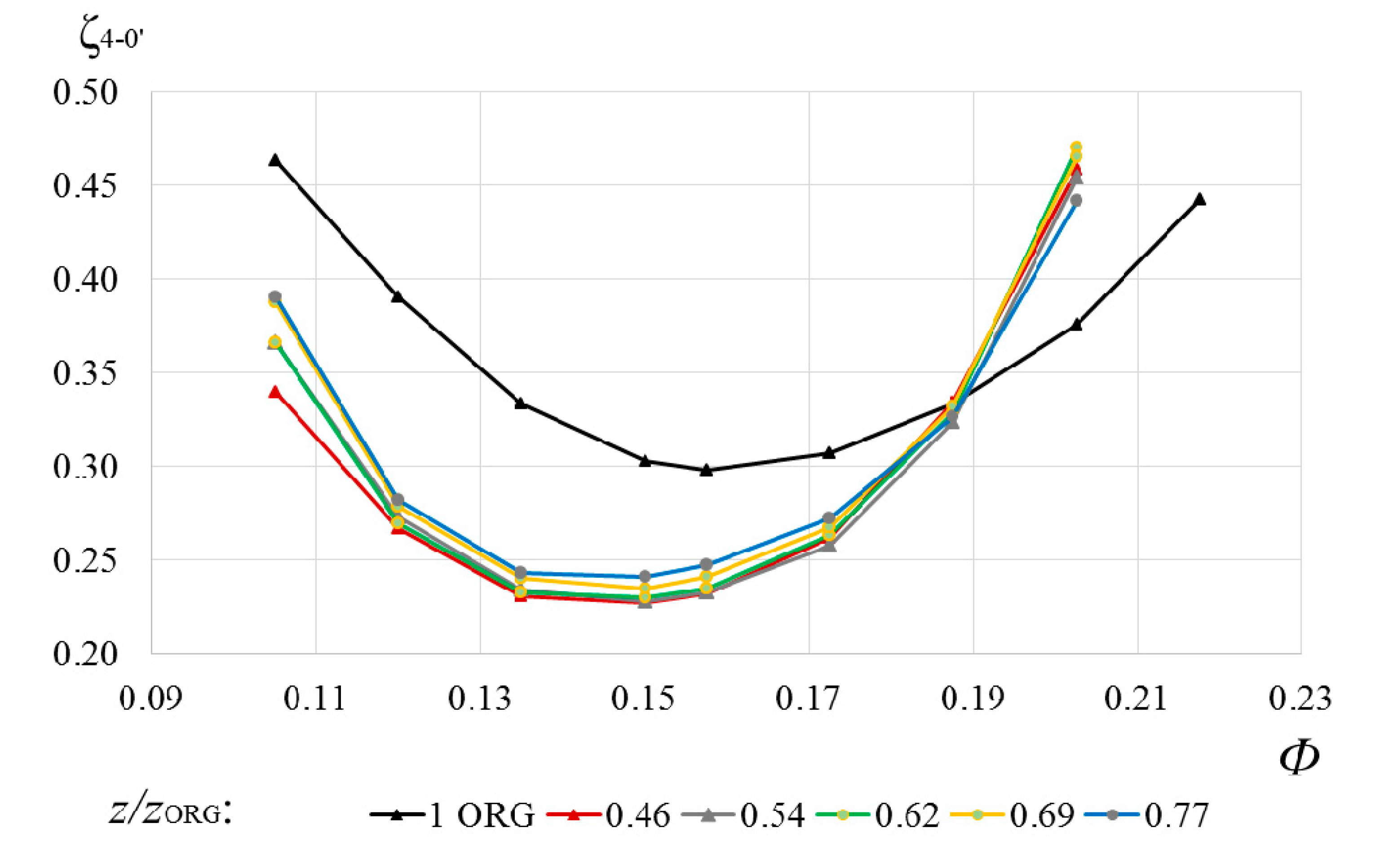
3.2. Stage with a Vane Number Ratio of 0.69. U-Bend Optimization

As recommended for the preliminary design, the RCh variant of the stage Φ d e s = 0.15, ψ T d e s = 0.45 and z / z O R G = 0.69 was chosen for further optimization. Its U-bend has been optimized for two parameters, R s and R h . The inner contour of the U-bend is the radius R s . The outer contour can be one radius R h , or two smaller radii with a straight space between them. Figure 18 shows the influence of these optimization parameters on the loss coefficient of the RCh.
The spread of points in the iterative calculation process is evident. It can be assumed that the values of the curvature radii according to the preliminary project R s O R G and R h O R G lie in the zone of optimum. In the range of values 0.9–1.15 of the preliminary design, the loss coefficient changes only due to the calculation error.
Formally, the smallest loss coefficient is for the RCh variant with R s / R s O R G = 1.035 and R h / R h O R G = 1.048. Figure 19 compares the RCh contours before and after optimization.
The optimized version increases the radial and axial dimensions of the flow path, which is undesirable. Taking into account the spread of points in the Figure 18, the advantage of the optimized U-bend cannot be recognized as proven. The authors believe that the U-bend after the preliminary design is practically optimal. The dimensions of the U-bends for the stages with ψ T d e s = 0.60 and ψ T d e s = 0.70 will be selected according to the preliminary design.

3.3. Return Channel Variants of the Stages with a Flow Rate of 0.15, a Loading Factor of 0.60

The preliminary design takes into account that the larger the loading factor ψ T d e s is, the closer is the surge limit to the design flow rate Φ d e s . Therefore, the flow angle at the surge is greater than that of the low loading factor stage. Accordingly, the vaneless diffuser width is larger and the angle α 4   d e s is smaller. It leads to the difference between return channels of stages with different loading factors.
Despite the difference in the diffuser width and the inlet flow angle, the results of the optimization of the RCh stage with ψ T d e s = 0.60 are qualitatively close to the RCh stage with ψ T d e s = 0.45. The minimum of the loss factor was also obtained with a wider RCh in relation to the width according to the preliminary design. Specifically, at the maximum possible width b 5 = b 6 .
Figure 20 shows normalized loss coefficient ζ d e s / ζ d e s O R G = f ( z / z O R G , b 5 / b 5 O R G ) of optimal RCh variants and their vane load.
The loss coefficient characteristics of the RCh variants with different numbers of vanes at the optimal vane height b 5 = b 6 and the preliminary design RCh characteristic are shown in Figure 21.
Unlike the stage with ψ T d e s = 0.45, the initial design provided practically minimal loss coefficient at Φ d e s = 0.15. However, due to optimization, the minimum loss coefficient is significantly reduced. In contrast to the RCh of the low-pressure stage with a reduced number of vanes, the characteristics are smooth over the entire flow rate range. It should be taken into account though that at this stage the surge limit is much closer to the Φ d e s .
Figure 22 shows the outlet flow angles of the RCh variants, the characteristics of which are presented in the Figure 21.
The return channel after the preliminary design has outlet angle of 88–89° over the entire range of flow rates. The return channel with the minimal loss coefficient with z / z O R G = 0.46 has unsatisfactory outlet angles. An acceptable compromise is the return channel with z / z O R G = 0.69 and average vane load Δ c ˜ a v   d e s = 0.37. The recommended number of vanes is the same as that of the low-pressure stage return channel, but the load is slightly higher.

3.4. Return Channel Variants of the Stages with a Flow Rate of 0.15, a Loading Factor of 0.70

For this stage with the higher loading factor, the vaneless diffuser width is larger too, and the angle α 4   d e s is smaller. This is the difference between return channels of stages with different loading factors. However, the results of the calculations qualitatively coincide with the previous stage. Minimal loss coefficient is at maximum possible width b 5 = b 6 , Figure 23.
The characteristics of the RCh variants with different numbers of vanes at the optimal height b 5 = b 6 and the characteristics of the variants according to the preliminary design are shown in Figure 24.
The preliminary design approximately provided a minimum of losses at Φ d e s = 0.15. Due to optimization (mainly by increasing b 5 / b 6 ), the minimum loss coefficient is significantly reduced. In contrast to the low-pressure stage, the characteristics are smooth over the comparatively narrow flow rate range.
Figure 25 shows the outlet flow angles of the variants represented in the Figure 24.
The return channel after the preliminary design has outlet angles of 88–89° over the entire range of the characteristic. The variant with z / z O R G = 0.46 and minimal loss coefficient has unsatisfactory outlet angle characteristic. An acceptable compromise is the variant with z / z O R G = 0.69 and average load Δ c ˜ a v   d e s = 0.32. The recommended number of vanes is the same as that of the return channels of stages with ψ T d e s = 0.45 and 0.60.

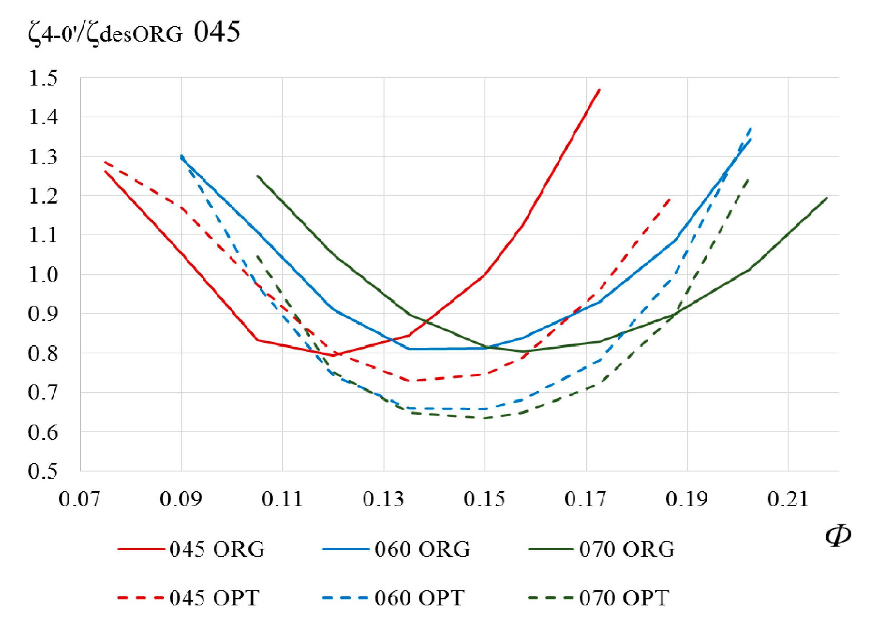
3.5. Characteristics of the Return Channels of Stages with Different Loading Factors

Figure 26 shows the characteristics of the RCh loss coefficients of the variants after the preliminary design and after optimization. The coefficients are relative to the loss coefficient of the RCh stage with ψ T d e s = 0.45 at Φ d e s = 0.15.
Figure 27 shows the outlet flow angles of the same return channels.

4. Discussion

The results of the preliminary design verification and return channels optimization have demonstrated the following.
With an increase of ψ T d e s , the width of the vaneless diffuser increases and the flow angle at the inlet to the RCh decreases. Return channels characteristics according to the preliminary design are shifted to the right for higher ψ T d e s . At ψ T d e s = 0.45, the characteristics of RCh do not correspond to the design flow rate Φ d e s . At ψ T d e s = 0.60 and 0.70 the discrepancy is insignificant.
The optimal number of vanes for all three return channels is 30% less than in the preliminary design. A larger height of vanes at the inlet is optimal. Vanes with a constant height are optimal for the stages with ψ T d e s = 0.60 and 0.70. By optimizing and choosing the proper dimensions of the RCh inlet of the stage with ψ T d e s = 0.45, the loss coefficient is reduced by 27% at the design flow rate. For the return channels of the stages with ψ T d e s = 0.60 and 0.70, the loss coefficient is reduced by about 20%.
Both according to the preliminary design and after optimization, the RCh of stages with wider diffusers and smaller flow angles are more efficient.
The optimization proposed is of some first level to find close to optimum main dimensions for a preliminary design. There are parameters that can be optimized in a final stage of design. For instance—3D leading edge instead of 2D, thickness of the leading edge, vane mean line configuration, and some other. Anyway, the authors’ experience shows that an optimization of main dimensions is of the first importance.

5. Conclusions

The results of the preliminary design and optimization of the RCh of three high flow rate stages with the same design flow rate coefficient 0.15 and different loading factors 0.45, 0.60 and 0.70 showed the feasibility of improving the preliminary size selection. Higher inlet vane heights and smaller vane numbers are optimal. The optimal vane number is the same for all three return channels of the stages with design loading factor 0.45, 0.60 and 0.70. It is 30% less than by the preliminary design. The vane load is rather high—about 0.35. The pressure diagrams’ analysis shows that in the studied return channels flow is accelerating on both vane surfaces. Therefore, high vane load does not lead to flow separation. It is a specific feature of high flow rate stages with long vaneless diffusers. As result, flow enters into RCh at high flow angle and low velocity. For return channels of stages with shorter vaneless diffusers and lesser flow coefficient, the vane optimal number could be higher.
Due to optimization, the loss coefficient of the return channels was significantly reduced.
The CFD optimization techniques have become available not only for research work, but also in design practice. The authors intend to continue researching return channels of stages with other design flow coefficient and loading factor. Preliminary design recommendations approaching the optimal solution will allow designers to find the final solution easier.

Author Contributions

Conceptualization, Y.G. and L.M.; methodology, Y.G. and A.R.; software, A.D.; validation, V.S. and O.S.; writing—review and editing, O.S. and L.M. All authors have read and agreed to the published version of the manuscript.

Funding

Funding for open access charge: Russian Academic Excellence Project 5-100. The calculations were performed using the supercomputer center SCC “Polytechnic”.

Conflicts of Interest

The authors declare no conflict of interest.

Abbreviations

Nomenclature
b vane height;
c absolute flow velocity;
D diameter;
L length;
m ¯ mass flow rate;
M u impeller Mach number;
p pressure;
R gas constant, curvature radius;
T temperature;
u 2 impeller blade velocity;
z number of vanes;
α flow angle with respect to tangent;
α v vane angle with respect to tangent;
δ vane thickness;
η efficiency;
ψ T loading factor;
ζ loss coefficient;
ρ gas density;
Φ relative flow rate coefficient.
Abbreviation
CFDComputational Fluid Dynamics;
MOGAMulti-Objective Genetic Algorithm;
Q3DQuasi-three-dimensional;
RChreturn channel
Subscripts
2, 3, 4, 5, 6, 0’indices of control sections;
avaverage;
crcritical;
desdesign;
hhub;
inlinlet;
LEleading edge;
OPToptimized;
ORGoriginal;
outoutlet;
prvane pressure side;
sshroud, vane suction side;
TEtrailing edge;
ubU-bend;
vvane.
Superscripts
*stagnation parameters;
– (superscript)related to D 2 or u 2 ;
~ (superscript)related to c 5

References

  1. Galerkin, Y.B. (Ed.) Proceedings of the Scientific School of Compressor Engineering SPbSPU; Publishing House of Scientific and Technical Information Center—SPb: Alexandria, VA, USA, 2010. [Google Scholar]
  2. Vasiliev, Y.S.; Rodionov, P.I.; Sokolovsky, M.I. New generation highly efficient centrifugal compressors. Scientific bases of calculation, development of methods for optimal design and production development. Ind. Sci. Russ. 2000, 10, 78–85. [Google Scholar]
  3. Galerkin, Y.B.; Danilov, K.A.; Popova, E.Y. Universal Modelling for Centrifugal Compressors-Gas Dynamic Design and Optimization Consepts and Application. In Proceedings of the Yokohama International Gas Turbine Congress, Yokohama, Japan, 22–27 October 1995. [Google Scholar]
  4. Galerkin, Y.; Danilov, K.; Popova, E. Design philosophy for industrial centrifugal compressor. In Inernational Conference on Compressors and Their Systems; City University: London, UK, 1999; pp. 465–480. [Google Scholar]
  5. Galerkin, Y.B. Turbocompressors. Workflow, Calculation and Design of the FLOW PATH; LLC “Information and Publishing Center” KHT: Moscow, Russia, 2010; p. 596. [Google Scholar]
  6. Galerkin, Y.B.; Rekstin, A.F. Vaneless diffuser of the centrifugal compressor stage design method. AIP Conf. Proc. 2019, 2141, 030007. [Google Scholar] [CrossRef]
  7. Rekstin, A.F.; Galerkin, Y.B. The primary design method development of centrifugal compressor impellers based on the analysis of the geometrical parameters. Oil Gas Eng. AIP Conf. Proc. 2019, 2141, 030052. [Google Scholar] [CrossRef]
  8. Solovyeva, O.; Drozdov, A. Mathematical model of centrifugal compressor vaneless diffuser based on CFD calculations. In Proceedings of the 2nd International Conference on High Speed Turbomachines and Electrical Drives (HSTED-2020)—E3S Web of Conferences, Prague, Czech Republic, 14–15 May 2020; EDP Sciences: Les Ulis, France, 2020; Volume 178, p. 01014. [Google Scholar]
  9. Rekstin, A.F.; Galerkin, Y.B. Low-flow rate centrifugal compressor stages primary design specificity. Bull. Perm Natl. Res. Polytech. Univ. 2018, 20, 43–54. [Google Scholar] [CrossRef]
  10. Rube, C.; Rossbach, T.; Wedeking, M.; Grates, D.R.; Jeschke, P. Experimental and Numerical Investigation of the Flow Inside the Return Channel of a Centrifugal Process Compressor. In Proceedings of the Turbine Technical Conference and Exposition, Montreal, ON, Canada, 15–19 June 2015; Volume 138, p. 101006-1. [Google Scholar] [CrossRef]
  11. Bisping, J.; Rossbach, T.; Grates, D.; Hildebrandt, A.; Jeschke, P. Influence of Diffuser Diameter Ratio on the Performance of a Return Channel Within A Centrifugal Compressor Stage. In Proceedings of the GPPS Forum 18 Global Power and Propulsion Society, Montreal, ON, Canada, 7–9 May 2018. [Google Scholar]
  12. Yagi, M.; Nishioka, T.; Kobayashi, H.; Nishida, H.; Yamamoto, S. Effects of return channel with splitter vanes on performance of multistage centrifugal compressor. In Proceedings of the Turbine Technical Conference and Exposition GT2015, Montreal, QC, Canada, 15–19 June 2015. [Google Scholar]
  13. Nishida, Y.; Kobayashi, H.; Nishida, H.; Sugimura, K. Performance improvement of a return channel in a multistage centrifugal compressor using multiobjective optimization. J. Turbomach. 2013, 135, 031026–310268. [Google Scholar] [CrossRef] [PubMed] [Green Version]
  14. Ji, C.; Li, C.; Fang, J.; Sun, Q. Loss Mechanism of Static Interstage Components of Multistage Centrifugal Compressors for Integrated Blade Design. Math. Probl. Eng. 2018, 16. [Google Scholar] [CrossRef]
  15. Veress, A.; Van den Braembussche, R. Inverse design and optimization of a return channel for a multistage centrifugal compressor. J. Fluids Eng. 2004, 126, 799806. [Google Scholar] [CrossRef]
  16. Jariwala, V.; Larosiliere, L.; Hardin, J. Design Exploration of a Return Channel for Multistage Centrifugal Compressors. In Proceedings of the ASME Turbo Expo 2016: Turbomachinery Technical Conference and Exposition GT2016, Seoul, Korea, 13–17 June 2016. [Google Scholar]
  17. De Bellis, F.; Guidotti, E.; Rubino, D.T. Centrifugal compressors return channel optimization by means of advanced 3D CFD. In Proceedings of the Turbine Technical Conference and Exposition GT2015, Montreal, QC, Canada, 15–19 June 2015. [Google Scholar]
  18. Hildebrant, A. Aerodynamic optimization of a centrifugal compressor return channel and U-turn with Genetic Algorithms. In ASME Turbo Expo 2011; ASME Paper GT201145067; ASME: New York, NY, USA, 2011. [Google Scholar]
  19. Hildebrandt, A. Numerical analysis of overall performance and flow phenomena of an automatically optimized treedimensional return channel system for multistage centrifugal compression systems. In ASME Turbo Expo 2012; ASME Paper GT2012-68559; ASME: New York, NY, USA, 2012. [Google Scholar]
  20. Marenina, L.; Galerkin, Y.; Drozdov, A. Stator elements optimization of centrifugal compressor intermediate type stage by CFD methods. In Proceedings of the 2nd International Conference on High Speed Turbomachines and Electrical Drives (HSTED-2020)—E3S Web of Conferences, Prague, Czech Republic, 14–15 May 2020; EDP Sciences: Les Ulis, France, 2020; Volume 178, p. 01020. [Google Scholar] [CrossRef]
  21. Kortikov, N.; Borovkov, A.; Voynov, I.; Kirillov, A.; Drozdov, A. Modeling the gas-dynamic characteristics of the low-flow and mid-flow model stages for an industrial centrifugal compressor. In Proceedings of the MATEC Web of Conferences, Saint-Petersburg, Russia, 5 December 2018; Volume 245, p. 04019. [Google Scholar]
  22. Borovkov, A.I.; Voinov, I.B.; Nikitin, M.A.; Galerkin, Y.B.; Rekstin, A.F.; Drozdov, A.A. Experience of performance modeling the single-stage pipeline centrifugal compressor. Oil Gas Eng.-AIP Conf. Proc. 2019, 2141, 030051. [Google Scholar] [CrossRef]
  23. Borovkov, A.I.; Voinov, I.B.; Galerkin, Y.B.; Drozdov, A.A.; Soldatova, K.V. Experimental characteristic simulation for two-stage pipeline centrifugal compressor. IOP Conf. Ser. Mater. Sci. Eng. 2019, 604, 012052. [Google Scholar] [CrossRef]
  24. Borovkov, A.; Voinov, I.; Galerkin, Y.; Nikiforov, A.; Nikitin, M.; Solovyeva, O.; Kabalyk, K. Issues of gas dynamic characteristics modeling: A study on a centrifugal compressor model stage. In Proceedings of the E3S Web of Conferences—International Scientific Conference on Energy, Environmental and Construction Engineering (EECE-2019), St. Petersburg, Russia, 19–20 November 2019; EDP Sciences: Les Ulis, Franc, 2019; Volume 140, p. 06003. [Google Scholar] [CrossRef] [Green Version]
  25. Galerkin, Y.B.; Rekstin, A.F.; Marenina, L.N.; Soldatova, K.V. Creation of parametrized model of return channel flow path for CFD-researches. In Proceedings of the Technique and tecHnology of Petrochemical and Oil and Gas Production—Materials of the 10th International Scientific and Technical Conference, Omsk, Russia, 26–29 February 2020; Publishing House of OmGTU: Omsk, Russia, 2020; pp. 127–128. [Google Scholar]
  26. Ries, V.F. Centrifugal Compressor Machines; Leningrad Branch: Moscow, Russia, 1981; p. 351. [Google Scholar]
  27. Den, G.N. The Mechanics of the Flow in Centrifugal Compressors; Mashinostroenie: Leningrad, Russia, 1973; p. 269. [Google Scholar]
  28. Livshits, S.P. Aerodynamics of Centrifugal Compressor Machines/SP Livshits; Mechanical Engineering: Leningrad, Russia, 1966; 340p, pp. 335–337. [Google Scholar]
  29. Seleznev, K.P.; Galerkin, Y.B. Centrifugal Compressors, L. Mechanical Engineering; Leningrad department: Saint Petersburg, Russia, 1982. [Google Scholar]
  30. Aungier, R.H. Centrifugal Compressors: A Stragedy for Aerodynamic Design and Analysis; Ronald, H.A., Ed.; ASME Press: New York, NY, USA, 2000; p. 320. [Google Scholar]
  31. Cumpsty, N.A. Compressor Aerodynamics; Longman Scientific and Technical: London, UK, 1989; 509p. [Google Scholar]
  32. Drozdov, A.; Rekstin, A. Analysis of the velocity diagrams of impellers of centrifugal compressor stages after the preliminary design. In Proceedings of the MATEC Web of Conferences, Saint-Petersburg, Russia, 5 December 2018; Volume 245, p. 04004. [Google Scholar] [CrossRef]
  33. Popova, E.Y. Optimization of the Main Parameters of Stages of Turbomachines Based on Mathematical Modeling. Ph.D. Thesis, Tech. SPbSPU, St. Petersburg, Russia, 1991. [Google Scholar]
  34. Rekstin, A.F.; Soldatova, K.V.; Galerkin, Y.B. Experience of application the computer program based on a simplified mathematical model for industrial centrifugal compressors candidates. IOP Conf. Series: Mater. Sci. Eng. 2019, 604, 012045. [Google Scholar] [CrossRef]
  35. Rekstin, A.F.; Soldatova, K.V.; Galerkin, Y.B.; Popova, E.Y. Verification of a simplified mathematical model of centrifugal compressor stages. In Proceedings of the International Scientific and Technical Conference Smart Energy Systems, SES 2019, Kazan, Russia, 19–20 September 2019; EDP Sciences: Les Ulis, France, 2019; Volume 124, p. 01005. [Google Scholar] [CrossRef] [Green Version]
  36. Rekstin, A.F.; Bakaev, B.V. Variant calculations of industrial centrifugal compressors based on a simplified mathematical model. // Scientific and technical statements of SPbSTU. Nat. Eng. Sci. 2018, 24, 24–38. [Google Scholar] [CrossRef]
  37. Sorokes, J.M.; Hutchinson, B.R. The Practical Application of CFD in the Design of Industrial Centrifugal Compressors. In Proceedings of the ASME International Mechanical Engineering Congress and Exposition, Challenges and Goals in Pipeline Compressors, Orlando, FL, USA, 5–10 November 2000. [Google Scholar]
  38. Galerkin, Y.; Rekstin, A.; Drozdov, A.; Soldatova, K.; Solovyeva, O.; Popova, E. The optimal gas dynamic design system of industrial centrifugal compressors based on Universal modeling method. In Proceedings of the 2nd International Conference on High Speed Turbomachines and Electrical Drives (HSTED-2020)—E3S Web of Conferences, Prague, Czech Republic, 14–15 May 2020; EDP Sciences: Les Ulis, France, 2020; Volume 178, p. 01028. [Google Scholar] [CrossRef]
  39. Galerkin, Y.B.; Marenina, L.N. Investigation and perfection of centrifugal compressor stages by CFD methods. Part 1. Compressors and pneumatics. In. J. Ind. Manuf. Eng. 2014, 1, 30–36. [Google Scholar]
  40. Marenina, L.; Galerkin, Y.; Soldatova, K. Computational fluid dynamics application for analysis of centrifugal compressor stage stator part. Int. J. Mech. Eng. Robot. Res. 2018, 7, 656–661. [Google Scholar] [CrossRef]
  41. Solovyeva, O. Mathematical Model for Gas-Dynamic Characteristics Calculation and Optimization of Vaneless Diffusers of Centrifugal Compressor Stages. Ph.D. Thesis, Tech. SPbSPU, Saint-Petersburg, Russia, 2018; p. 162. [Google Scholar]
  42. Rekstin, A.F.; Drozdov, A.A.; Solovyova, O.A.; Galerkin, Y.B. Comparison of two mathematical models of a vaneless diffuser of a centrifugal compressor stage. Compress. Pneum. 2019, 1, 2–10. [Google Scholar]
  43. Luke, S. Essentials of Metaheuristics. A Set of Undergraduate Lecture Notes; Lulu.com: Cedar Fork, NC, USA, 2009. [Google Scholar]
  44. Yoshimura, M.; Misaka, T.; Shimoyama, K.; Obayashi, S. Topology Optimization of Flow Channels with Heat Transfer Using a Genetic Algorithm Assisted by the Kriging Model. In Advances in Evolutionary and Deterministic Methods for Design, Optimization and Control in Engineering and Sciences, Computational Methods in Applied Sciences; Springer International Publishing AG: Berlin, Germany, 2019; Volume 48. [Google Scholar] [CrossRef]
  45. Luo, C.; Shimoyama, K.; Obayashi, S. A Study on Many-Objective Optimization Using the Kriging-Surrogate-Based Evolutionary Algorithm Maximizing Expected Hypervolume Improvement. Math. Probl. Eng. 2015, 15. [Google Scholar] [CrossRef] [Green Version]
Figure 1. Stator part of the stage after preliminary design.
Energies 13 05968 g001
Figure 2. Return channel loss coefficient (ASNSYS CFX) [10].
Energies 13 05968 g002
Figure 3. PC software PDCC-G8E for variant calculation and preliminary design: design parameters for the compressor first stage.
Energies 13 05968 g003
Figure 4. The flow path of the stator part of the stage with Φ d e s = 0.15 and ψ T d e s = 0.60.
Energies 13 05968 g004
Figure 5. Flow structure at the meridional (above) and radial (below) planes. Boundary conditions on the walls of the vaneless diffuser: “no slip” on the left, “free slip” on the right. Velocity legend: from 0 to 170 m/s.
Energies 13 05968 g005
Figure 6. Scheme of the outlet section of the RCh for CFD calculation.
Energies 13 05968 g006
Figure 7. The outlet flow structure at L 1 = R h 6 (above), L 1 = 3 R h 6 (center), L 2 = 6 R h 6 (below). Velocity legend: from 0 to 170 m/s.
Energies 13 05968 g007
Figure 8. Flow structure of the RCh variants made with splitter vanes (left) and without splitter vanes (right). Velocity legend: from 0 to 170 m/s.
Energies 13 05968 g008
Figure 9. The flow in the return channel with different numbers of splitter vanes. Left: standard solution with splitter vanes after each second vane. Right: splitter vanes after each vane. Velocity legend: from 0 to 170 m/s.
Energies 13 05968 g009
Figure 10. Computational domain in the radial (a) and meridional (b) planes.
Energies 13 05968 g010
Figure 11. Normalized loss coefficient of return channels with different z / z O R G , b 5 / b 5 O R G and their vane load. Dotted— Δ c ˜ a v   d e s .
Energies 13 05968 g011
Figure 12. Vane load Δ c ˜ a v as a function of the flow coefficient. b ¯ 5 O P T = 1.2 b ¯ 5 O R G .
Energies 13 05968 g012
Figure 13. Vane pressure diagrams for different RCh variants. Left: z = z O R G , right: z = 0.54 z O R G .
Energies 13 05968 g013
Figure 14. The streamlines in the RCh with z / z O R G = 0.54 on three vane-to-vane surfaces. Distance from the diaphragm: 0.02 b ¯ 5 (left), 0.50 b ¯ 5 (middle), and 0.98 b ¯ 5 (right). Velocity legend: from 0 to 170 m/s.
Energies 13 05968 g014
Figure 15. The circumferential component of the velocity at the RCh exit. (left) z = z O R G , (middle) z = 0.69 z O R G , (right) z = 0.54 z O R G . Circumferential velocity legend: from -15 to 40 m/s.
Energies 13 05968 g015
Figure 16. Outlet flow angle for a number of RCh variants at different Φ .
Energies 13 05968 g016
Figure 17. The loss coefficient characteristics of the return channel after preliminary design and of the optimized variants with different numbers of vanes.
Energies 13 05968 g017
Figure 18. Influence of the curvature radii of the U-bend on the return channel loss coefficient.
Energies 13 05968 g018
Figure 19. U-bend according to the preliminary design (gray) and after optimization (red).
Energies 13 05968 g019
Figure 20. Normalized loss coefficient of return channels with different z / z O R G , b 5 / b 5 O R G and their vane load. Dotted— Δ c ˜ a v   d e s .
Energies 13 05968 g020
Figure 21. The loss coefficient characteristics of the return channel after preliminary design and of the optimized variants with different numbers of vanes.
Energies 13 05968 g021
Figure 22. The outlet flow angles of the RCh variants, the characteristics of which are presented in the Figure 21.
Energies 13 05968 g022
Figure 23. Normalized loss coefficient of return channels with different z / z O R G , b 5 / b 5 O R G and their vane load. Dotted— Δ c ˜ a v   d e s .
Energies 13 05968 g023
Figure 24. Loss coefficient characteristics of the RCh variants with different numbers of vanes at the optimal height b 5 = b 6 and the characteristics of the variants according to the preliminary design.
Energies 13 05968 g024
Figure 25. Outlet flow angles from the original RCh, and optimized RCh with b 5 / b 6 = 1.
Energies 13 05968 g025
Figure 26. Characteristics of the loss coefficients of the RCh of the stages with Φ d e s = 0.15 and different loading factors ψ T d e s = 0.45, 0.60, 0.70.
Energies 13 05968 g026
Figure 27. Angles of outlet flow of the RCh of the stages with Φ d e s = 0.15 and different loading factors ψ T d e s = 0.45, 0.60, 0.70.
Energies 13 05968 g027
Table 1. PC software PDCC-G8E for variant calculation and preliminary design: main parameters of the selected compressor variant.
#Stage Φ M u D 2 D h u b ψ T Re u η
13D + VLD0.15000.72191.70640.35000.60002.930 × 10070.8158
23D + VLD0.12030.68031.70640.35000.60003.650 × 10070.8652
Compressor efficiency0.8391
RPM, 1/min2749.07
Power consumption, kW7302.16
Tip speed, m/s245.62
Body volume, m332.99
Table 2. Dimensions of the return channels of the stages with Φ d e s = 0.15 and ψ T   d e s = 0.45, 0.60 and 0.70 (preliminary design).
ψ T d e s = 0.45 ψ T d e s = 0.60 ψ T d e s = 0.70
b 3 / b 2 = b 4 / b 2 = b ¯ 4 0.7910.8790.904
b ¯ 5 / b ¯ 4 1.2261.2261.226
b ¯ 6 / b ¯ 5 1.3561.2201.179
D ¯ 4 = D ¯ 5 1.951.951.95
Φ c r 0.0640.0860.099
Publisher’s Note: MDPI stays neutral with regard to jurisdictional claims in published maps and institutional affiliations.

