The Effect of External Geometry Factors on the Characteristics of Flow Profiles and Segregation in a Vertical Sinter Cooling Bed

Abstract
:1. Introduction
2. Simulated Methodology
2.1. DEM Method
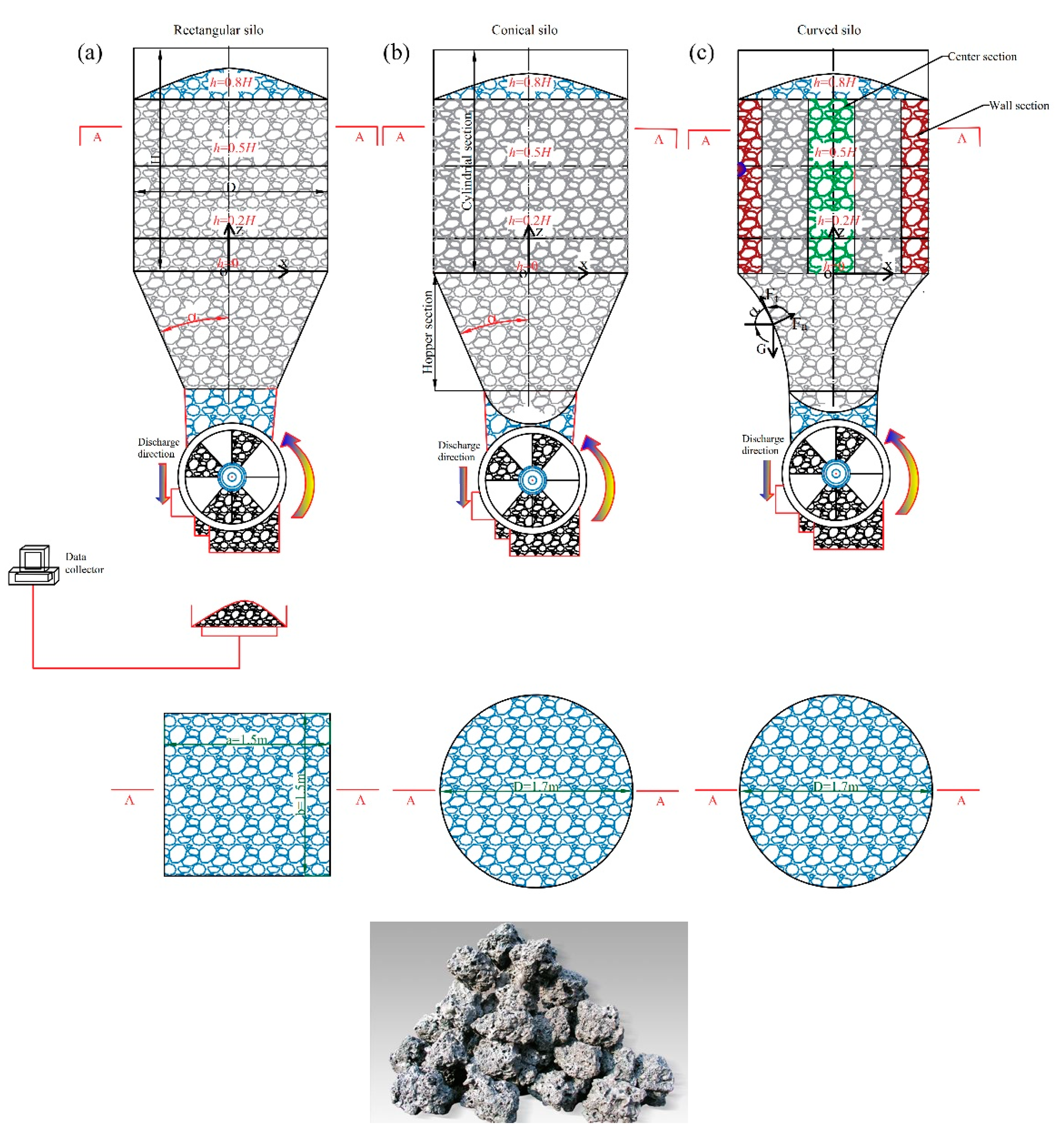
2.2. Characteristics of the Geometry Types of VSCBs
2.3. Experimental Packed Bed and Method
2.4. Quantitative Description of Particle Flow and Segregation Behaviours
2.4.1. The Flow Profiles for Particle Layers
2.4.2. The Variation in Segregation for Particle Layers
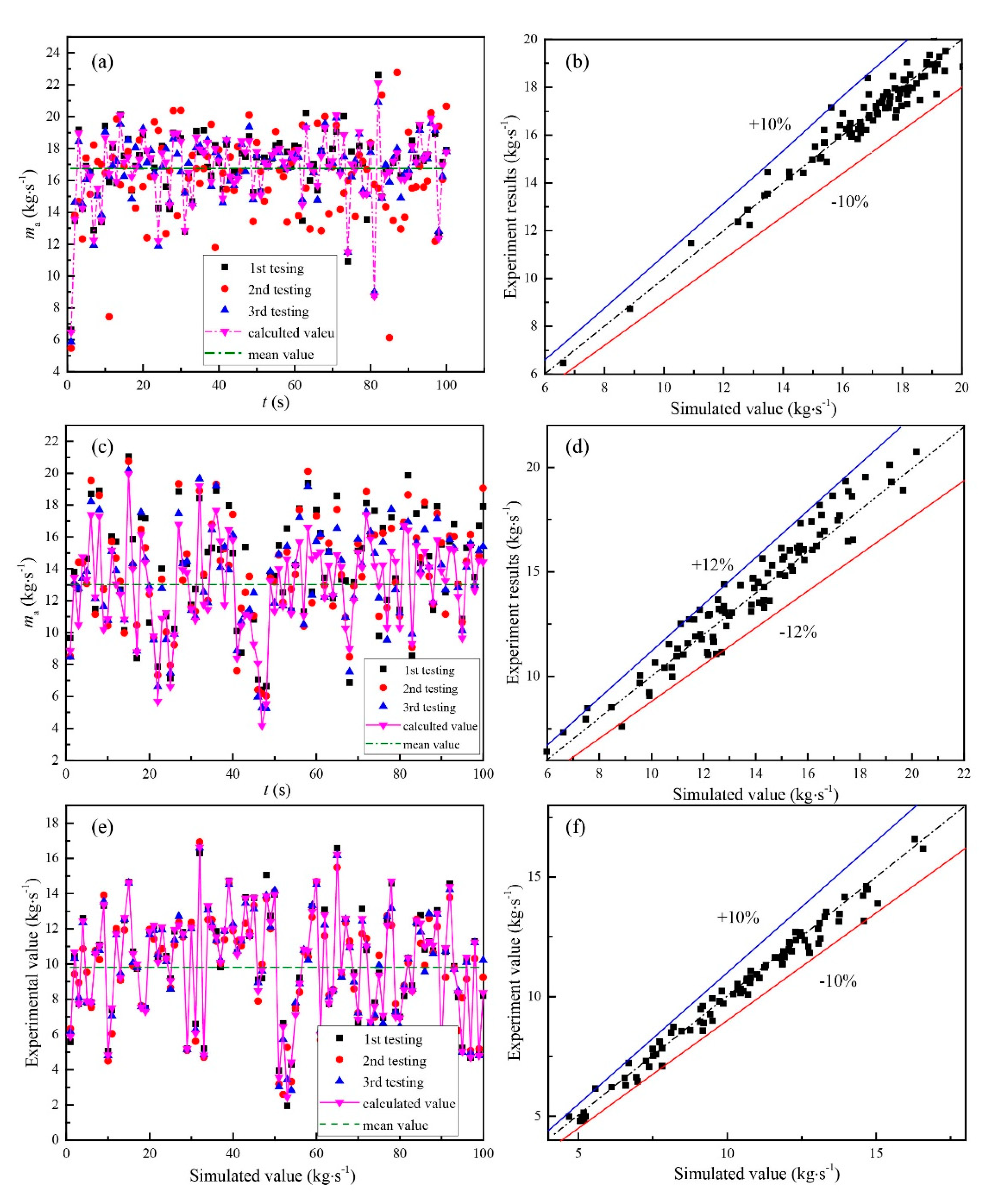
3. Validation Model
4. Results and Discussion
4.1. Effect of the Three Geometry Types with Different Normalized Outlets on Flow Profiles (d0/D0)
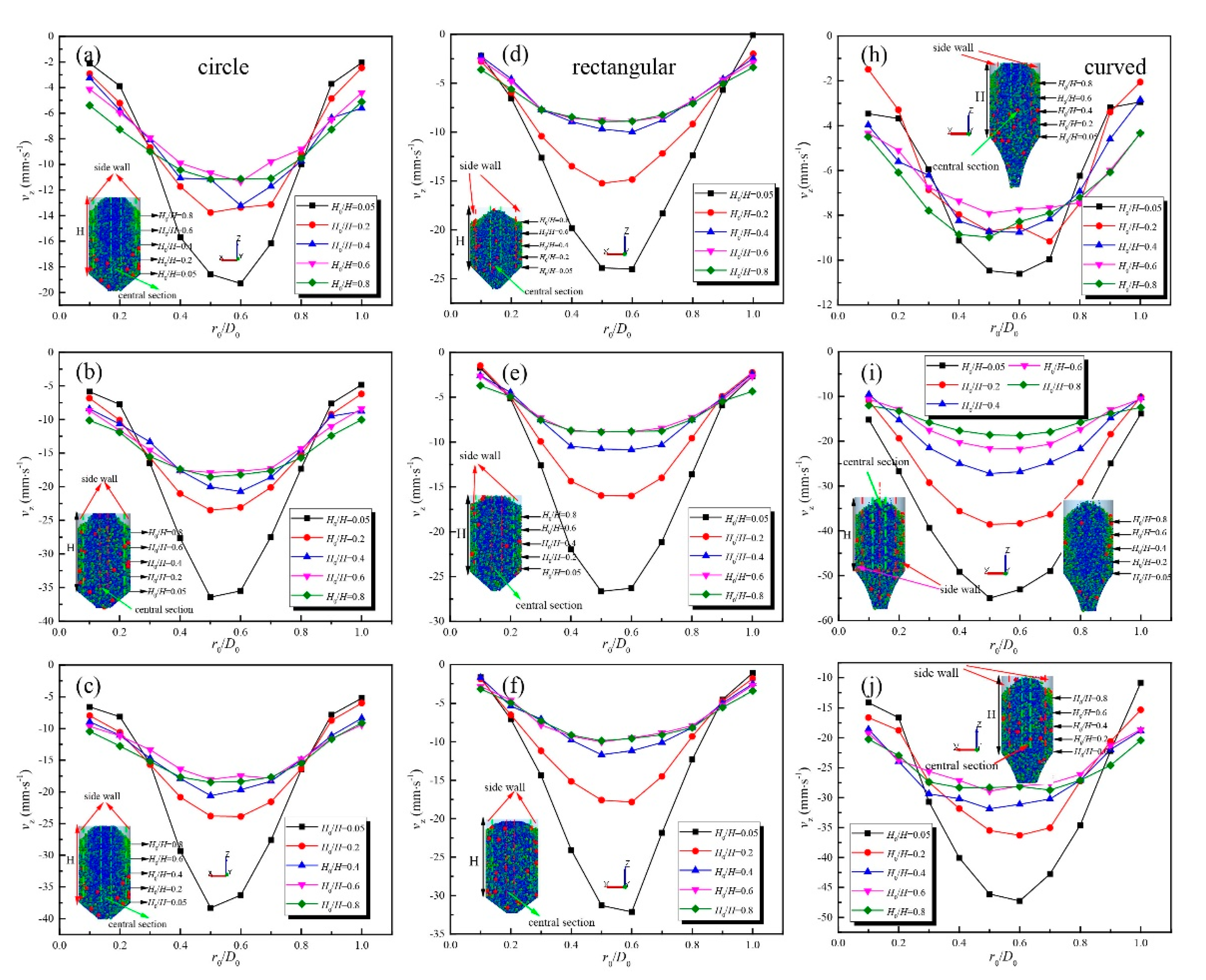
4.1.1. Velocity Distribution of the Sinter Layers for the Three Geometry Types with Different Outlets Normalized (d0/D0)
4.1.2. MFI of Sinter Layers for the Three Geometry Types with Different Outlets Normalized (d0/D0)
4.2. Effect of the Three Geometry Types with Different Half Hopper Angles on Flow Profiles
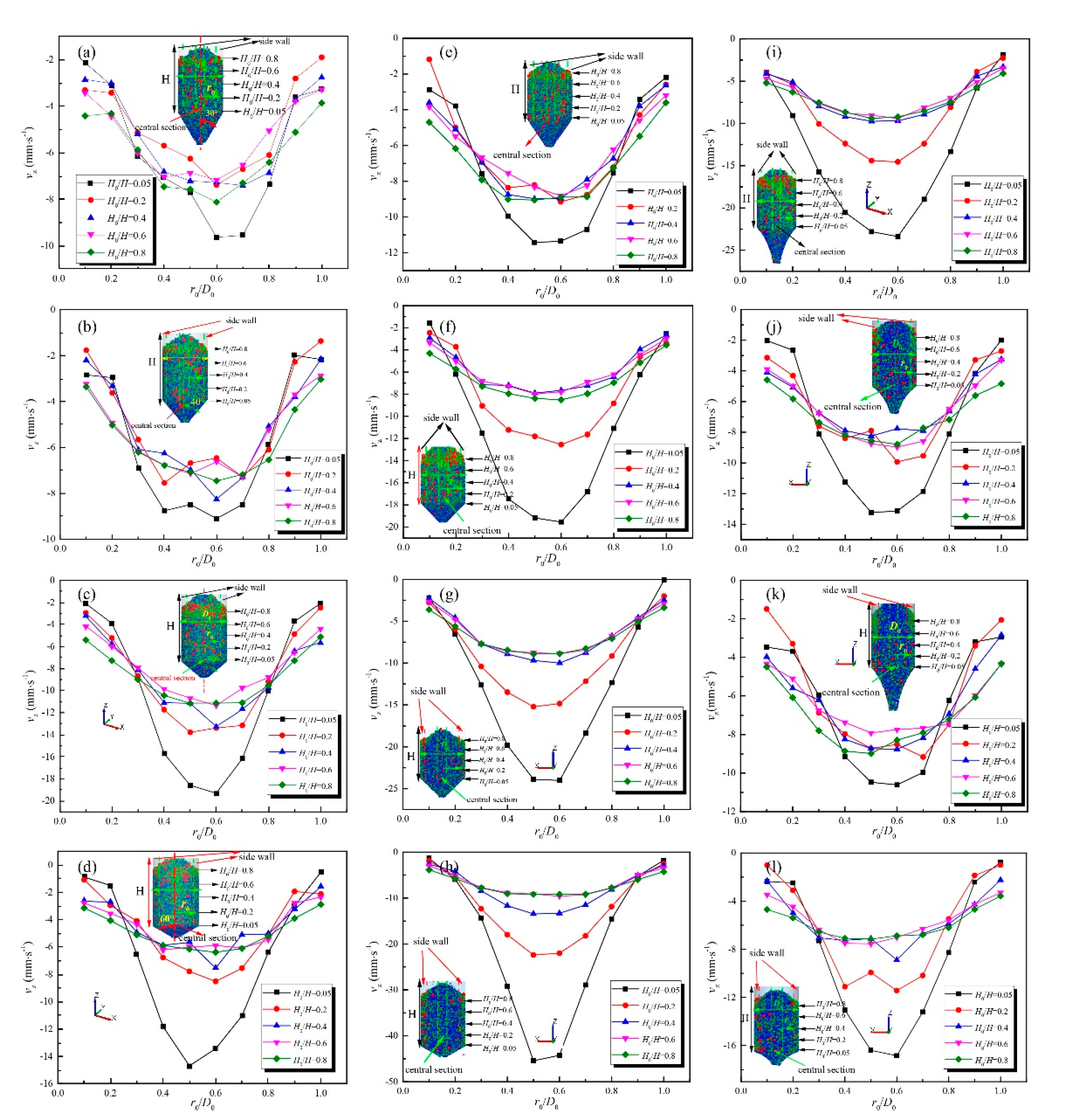
4.2.1. Velocity Distribution of Sinter Layers for the Three Geometry Types with Different Half Hopper Angles
4.2.2. MFI of Sinter Layers for the Three Geometry Types with Different Half Hopper Angles
4.3. Effect of the Three Geometry Types with Different Geometry Factors on Flow Profiles (D0/dp)
4.3.1. Velocity Distribution of Sinter Layers for the Three Geometry Types with Different Geometry Factors
4.3.2. MFI of Sinter Layers for the Three Geometry Types with Different Geometry Factors
4.4. Effect of the External Geometry Factor on Segregation in the VSCB
4.4.1. The Effect of the External Geometry for Different Normalized Outlets on the Segregation Index
4.4.2. Effect of the External Geometry for Different Half Hopper Angles on the Segregation Index
4.4.3. The Effect of the External Geometry for Different Geometry Factors on the Segregation Index
5. Conclusions
- (1)
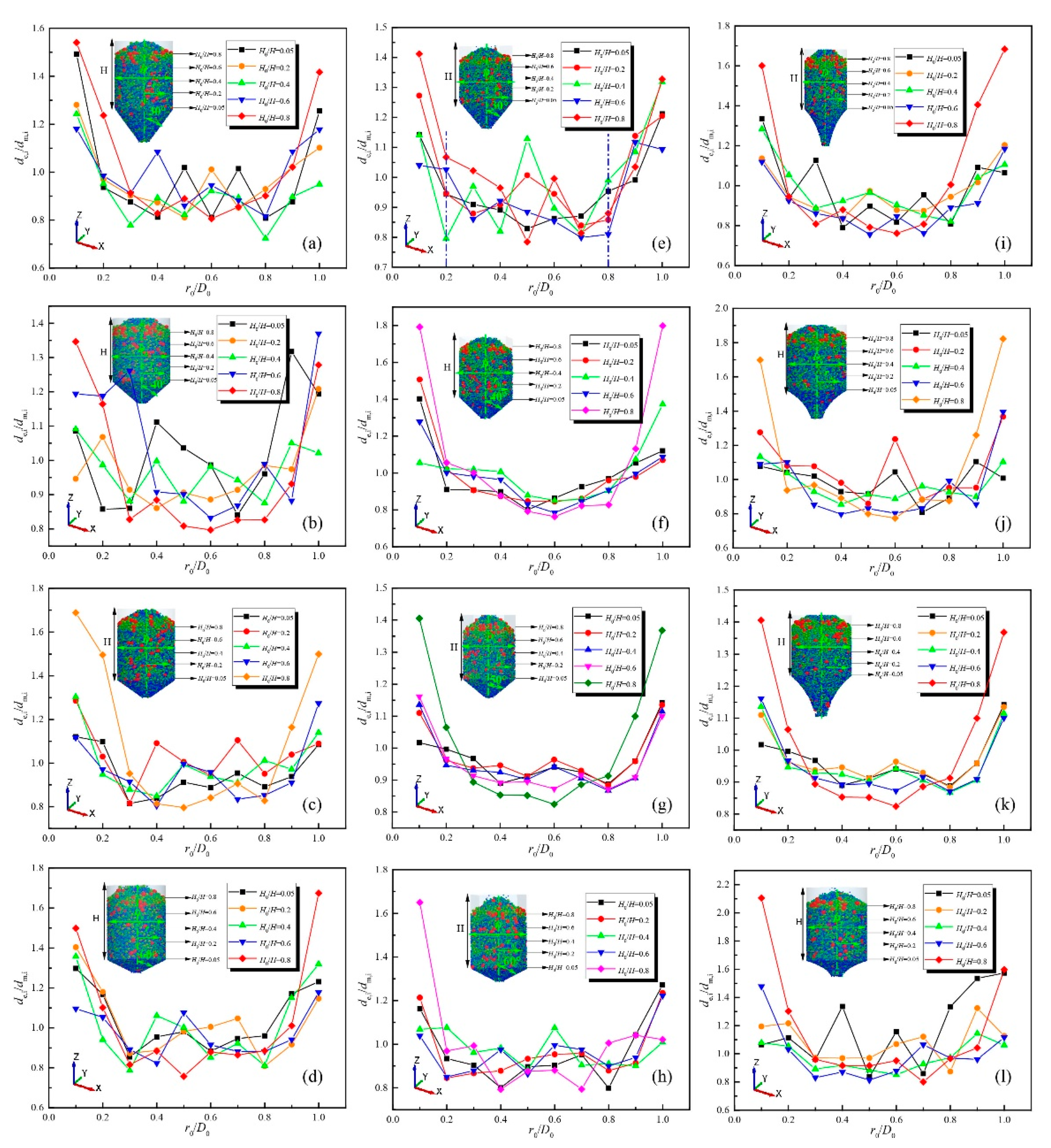
- The characteristics of the flow profiles and segregation for the three geometry types vary with the normalized outlet: the velocity distribution greatly increases in the central section and gradually decreases in the sidewall section with a normalized outlet increase for the circular and rectangular geometry types, while the corresponding values in the central and sidewall sections sustainably increase with a normalized outlet increase for the curved geometry type. The stabilization of the velocity distribution in the sinter layers gradually decreases, and the height of the mass flow pattern increases as the normalized outlet increases for the circular and rectangular geometry types, while slight fluctuations in the magnitude of MFI varies with the normalized outlet. The optimal performance of the flow pattern is near the normalized outlet of 0.3. Regarding the evolution of the segregation index for the three geometry types with different normalized outlets, the magnitude of the segregation index dramatically decreases in the sidewall section, while the corresponding value in the centre remains stable with a normalized outlet increase for the three geometry types. A comparison of the effectiveness in controlling the segregation index for the three geometry types shows that the curved geometry type has a significant effect on improving the segregation index distribution in sinter layers.
- (2)
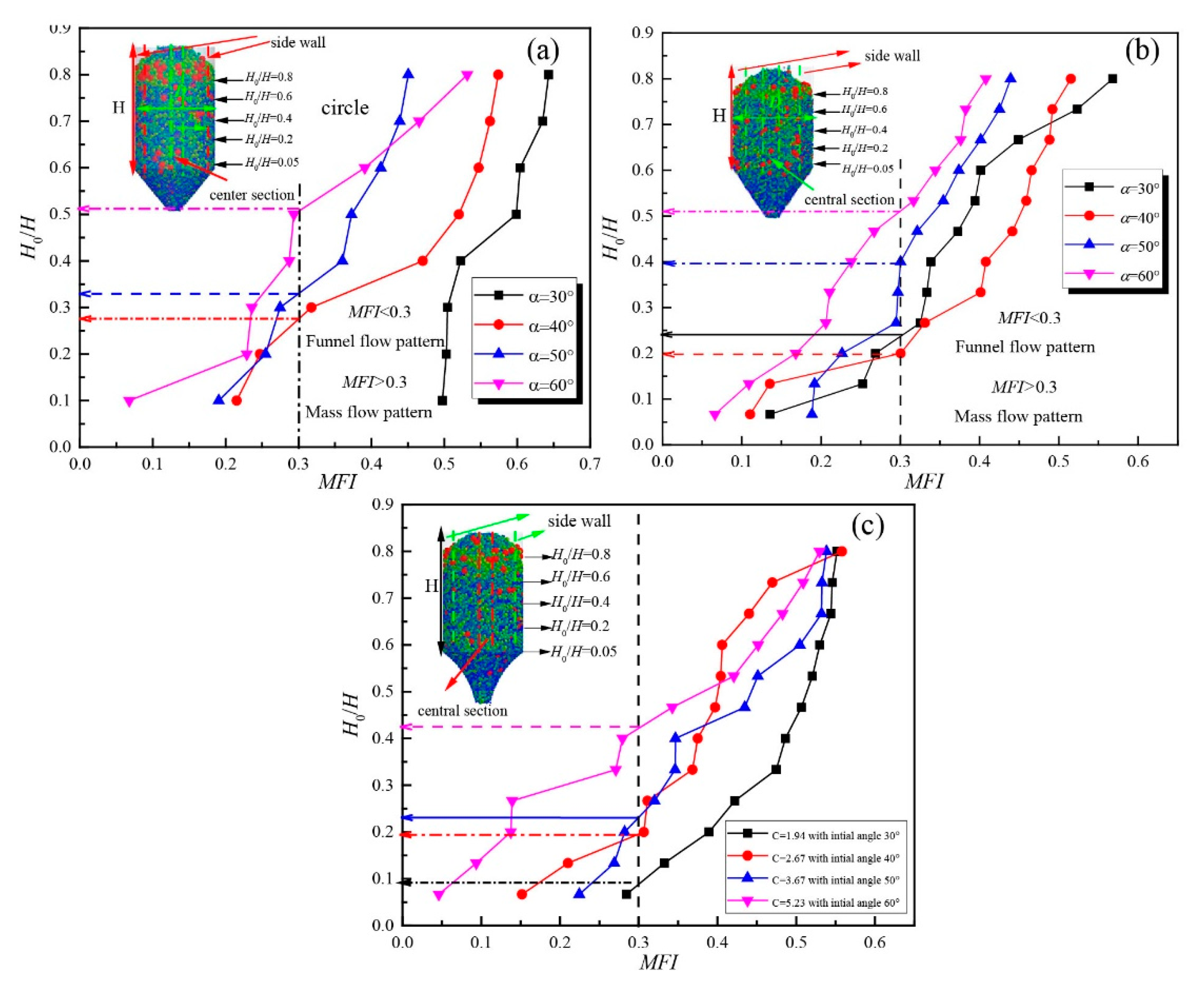
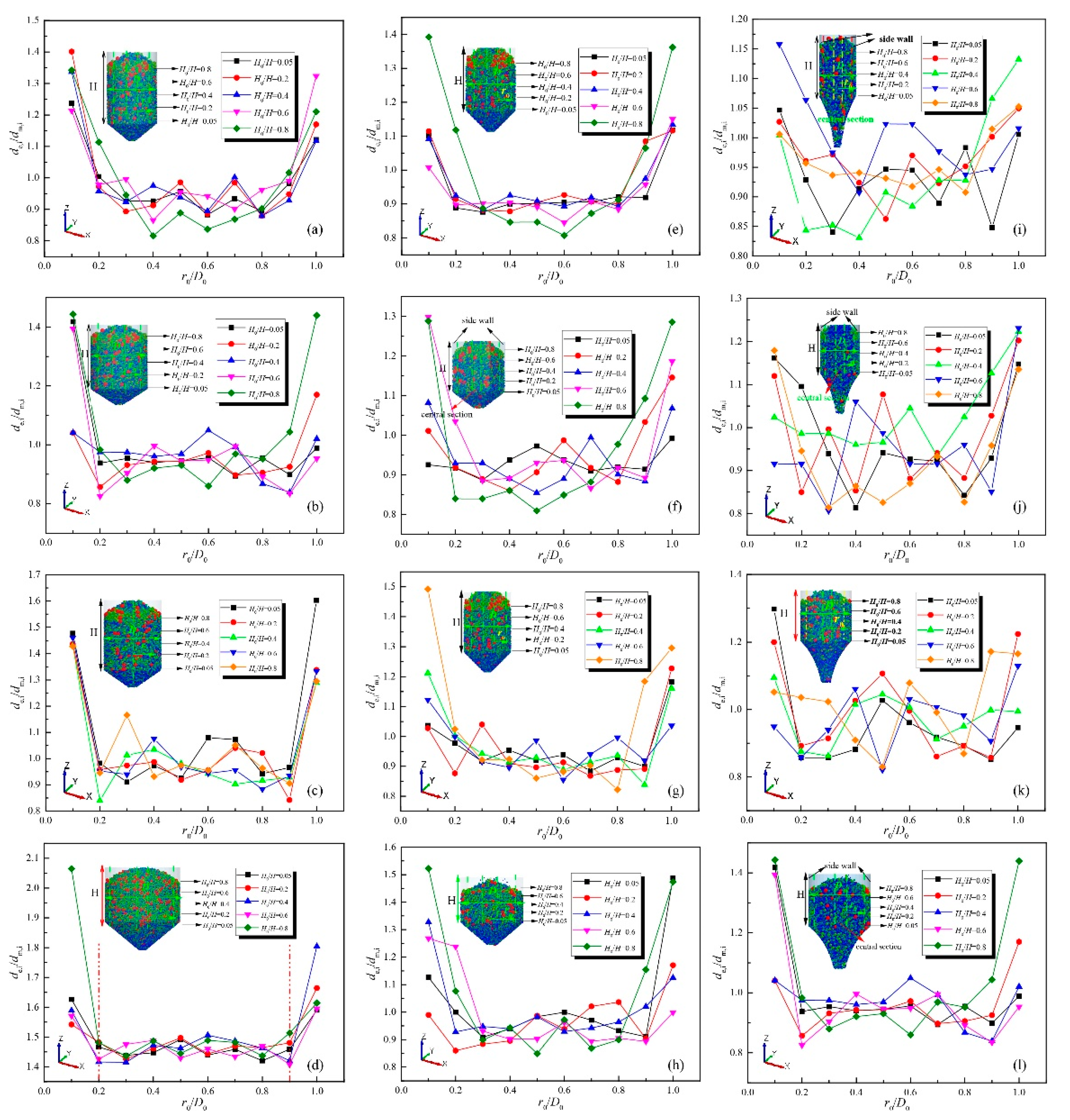
- The characteristics of the flow profiles and segregation for the three geometry types vary with the half hopper angle: the velocity distribution of the sinter layers for the three geometry types with different half hooper angles (the curved geometry with an identical initial angle to that of the circular and rectangular geometries, especially). The variation in the magnitude of the velocity distribution gradually increases prior to remaining constant in the central section for the circular geometry, while the opposite trend is observed for the curved geometry with an increase in the half hopper angle. However, the magnitude of the velocity distribution in the central section dramatically increases with an increase in the half hopper angle for the rectangular geometry. With respect to the evolution of MFI for the three geometry types varying with half hopper angle, the height of the mass flow has a negative correlation with the half hopper angle. With respect to the segregation index varying with half hopper angle for the rectangular geometry, the segregation index slightly fluctuates and gradually increases prior to a drastic decrease, while the corresponding value gradually decreases and remains stable prior to greatly oscillating with an increase in the half hopper angle. In terms of the variation of the segregation index for the curved geometry type, the segregation index gradually decreases in the sidewall, and the corresponding value remains constant in the centre with a half hopper angle.
- (3)
- The characteristics of the flow profiles and segregation for the three geometry types vary with the geometry factor: the velocity distributions for the three geometry types vary with the different geometry factors. The magnitude of the velocity distribution in the sinter layers drastically increases prior to remaining constant in the central section for the circular geometry type, while the corresponding value for the curved geometry slightly increases prior to remaining stable in the central section with an increase in the geometry factor. The magnitude of the velocity continuously dramatically increases with an increase in the geometry factor. By comparison, the height of the mass flow pattern for the curved geometry is four-fold and three-fold those of the circular and rectangular geometry types, respectively. In terms of the evolution of the segregation index for the three geometry types varying with an increase in the geometry factor, the magnitude of the segregation index slightly fluctuates prior to remaining stable in the central section, and the corresponding value sustainably increases in the sidewall section, while a similar trend in the variation of the segregation index is recorded for the rectangular geometry type. Regarding the variation in the segregation index in sinter layers with an increase in the geometry factor for the curved geometry type, the magnitude of the segregation index oscillates around a value of 1, while the corresponding value slightly increases in the sidewall.
Author Contributions
Funding
Acknowledgments
Conflicts of Interest
Nomenclature
| mi | Mass of particle i (kg) |
| vi | Translational velocity of particle i (m∙s−1) |
| i | Particle i |
| t | Time (s) |
| g | Gravitational acceleration (m∙s−2) |
| ni | Number of contact particles |
| Fcn | Normal contact force (N) |
| Fdn | Normal damping force (N) |
| Fct | Tangential contact force (N) |
| Fdt | Tangential contact force (N) |
| Ii | Inertial moment of particle i (kg∙m−2) |
| ωi | Angular velocity of particle i (rad∙s−1) |
| Tt,ij | Tangential torque (N·m) |
| Tr,ij | Rolling friction torque (N·m) |
| E* | Equivalent young’s modulus (MPa) |
| r* | Equivalent radius (m) |
| δn | Overlap distance of two particles (m) |
| nij | Normal unit vector (-) |
| υ | Poisson’s ratio (-) |
| G* | Equivalent shear modulus (MPa) |
| tij | Tangential unit vector (-) |
| e | Restitution coefficient (-) |
| Sn | Normal elastic constant coefficient (MPa∙m−2) |
| St | Tangential elastic constant coefficient (MPa∙m−2) |
| rij | Contact radius of two particles (m) |
| n | Normal direction component (-) |
| t | Tangential direction component (-) |
| m* | Equivalent mass (kg) |
| μ | Coefficient of particles friction (-) |
| vijt | Tangential velocity (m∙s−1) |
| vijn | Normal velocity (m∙s−1) |
| ωt,ij | Tangential angular velocity of particle i (rad∙s−1) |
| r | Error value (%) |
| fcal,i | Calculation results in the ith case (kg·s−1) |
| fexp,i | Experiment results in the ith case (kg·s−1) |
| vw | Velocity of the sidewall (mm·s−1) |
| vc | Velocity of the central section (mm·s−1) |
| ms | Average mass flow rate (kg·s−1) |
| VUIj | Velocity uniformity index in the jth layer |
| vjk | Velocity of the kth column in the jth layer (mm·s−1) |
| vave,j | Velocity of the jth layer (mm·s−1) |
| vr | Velocity of the rth time step in operating time (mm·s−1) |
| rij | Shear stress of unit element (MPa) |
| |r*| | Shear rate tensor |
| ρb | Bulk density of sinter layers (kg·m3) |
| D0 | Dimension of the outlet of VSCB (mm) |
| G | Acceleration of gravity of mass (m·s−2) |
| n | Total number of experiments |
| α | Half hopper angles (°) |
Abbreviations
| DEM | Discrete element method |
| VSCB | Vertical sinter cooling packed bed |
| VUI | Velocity uniformity index |
| MFI | Mass flow index |
| Fr | Froude number |
References
- Qiu, L.; Li, Y.L.; Feng, Y.H.; Zhang, X.X. Numerical simulation of waste heat recovery for blast furnace slag with multi-particles distribution in moving bed. J. Eng. Thermophys. 2019, 40, 2407–2412. [Google Scholar]
- Feng, Y.; Zhang, X.; Yu, Q.; Shi, Z.; Liu, Z.; Zhang, H.; Liu, H. Experimental and numerical investigations of coke descending behavior in a coke dry quenching cooling shaft. Appl. Therm. Eng. 2008, 28, 1485–1490. [Google Scholar] [CrossRef]
- Wang, H.; Chu, M.; Bao, J.; Liu, Z.; Tang, J.; Long, H. Experimental study on impact of iron coke hot briquette as an alternative fuel on isothermal reduction of pellets under simulated blast furnace conditions. Fuel 2020, 268, 117339. [Google Scholar] [CrossRef]
- Piringer, H. Lime shaft kilns. Energy Proc. 2017, 120, 75–95. [Google Scholar] [CrossRef]
- Mellmann, J.; Hoffmann, T.; Furll, C. Mass flow during unloading of agricultural bulk materials from soils depending on particle form, flow properties and geometry of the discharge opening. Powder Technol. 2014, 253, 46–52. [Google Scholar] [CrossRef]
- Lareo, C.; Nedderman, R.; Fryer, P.J. Practical velocity profiles for solid-liquid food flows in vertical pipes part Ⅱ. Multiple particles. Powder Technol. 1997, 93, 35–45. [Google Scholar] [CrossRef]
- Merwe, W.J.; Toit, C.G.; Kruger, J.H. Influent of the packing structure on the flow through packed beds with small cylindrical diameter to particle diameter ratios. Nucl. Eng. Des. 2020, 365, 110700. [Google Scholar] [CrossRef]
- Qian, P.; Wang, J.-Y.; Wu, Z.-H.; Yang, J.; Wang, Q.-W. Performance comparison of methane steam reforming in a randomly packed bed and a grille-sphere composite packed bed. Energy Convers. Manag. 2019, 193, 39–51. [Google Scholar] [CrossRef]
- Babout, L.; Grudzien, K.; Waktola, S.; Miskiewicz, K.; Adrien, J.; Maire, E. Quantitative analysis of flow dynamics of organic granular materials inside a versatile silo model during time-lapse X-ray tomography experiments. Comput. Electron. Agric. 2020, 172, 105346. [Google Scholar] [CrossRef]
- Zaki, M.; Siraj, M.-S. Study of a flat-bottomed cylindrical silo with different orifice shapes. Powder Technol. 2019, 354, 641–652. [Google Scholar] [CrossRef]
- Zhang, C.; Gao, J.; Zeng, L.; Xia, Y.; Xie, W.; Ye, W. Experimental analysis of the resistance of packed beds based on the morphology of cylindrical. Powder Technol. 2020, 369, 238–247. [Google Scholar] [CrossRef]
- Liu, H.; Jia, F.-G.; Xiao, Y.-W.; Han, Y.-L.; Li, G.-G. Numerical analysis of the effect of the contraction rate of the curved hopper on flow characteristics of the silo discharge. Powder Technol. 2019, 356, 858–870. [Google Scholar] [CrossRef]
- Yang, X.; Jian, X.; Zhe, H.L. DEM study on ternary-size particle segregation during the sinter burden charging process. Powder Technol. 2019, 343, 422–435. [Google Scholar]
- Huang, A.N.; Cheng, T.H.; Hsu, W.Y. DEM study of particle segregation in a rotating drum with internal diameter variations. Powder Technol. 2020, 378, 430–440. [Google Scholar]
- Yang, J.C.; Guo, Y.; Buettner, K.E. DEM investigation of shear flows of binary mixtures of non-spherical particles. Powder Technol. 2019, 202, 383–391. [Google Scholar] [CrossRef]
- Govender, N.; Daniel, N.W.; Wu, C.Y. Hopper flow of irregularly shaped particles (non-convex polyhedral): GPU-based DEM simulation and experimental validation. Chem. Eng. Sci. 2018, 188, 34–51. [Google Scholar] [CrossRef] [Green Version]
- Ma, H.Q.; Zhao, Y.Z. Modelling of the flow of ellipsoidal particles in a horizontal rotating drum based on DEM simulation. Chem. Eng. Sci. 2017, 172, 636–651. [Google Scholar] [CrossRef]
- Qiu, J.Y.; Ju, D.C.; Zhang, J.L.; Xu, Y.S. DEM simulation of particle flow in a parallel-hopper bell-less charging apparatus for blast furnace. Powder Technol. 2017, 314, 218–231. [Google Scholar] [CrossRef]
- Cundall, P.; Strack, O. Modeling of Microscopic Mechanisms in Granular Material. Stud. Appl. Mech. 1983, 7, 137–149. [Google Scholar] [CrossRef]
- Aleshin, V.V.; Abeele, K.V.D. Preisach analysis of the Hertz–Mindlin system. J. Mech. Phys. Solids 2009, 57, 657–672. [Google Scholar] [CrossRef]
- Aleshin, V.; Abeele, K.V.D. General solution to the Hertz–Mindlin problem via Preisach formalism. Int. J. Non-Linear Mech. 2013, 49, 15–30. [Google Scholar] [CrossRef]
- Zhang, Y.; Jia, F.; Zeng, Y.; Han, Y.; Xiao, Y. DEM study in the critical height of flow mechanism transition in a conical silo. Powder Technol. 2018, 331, 98–106. [Google Scholar] [CrossRef]
- Zeng, Y.; Jia, F.; Zhang, Y.; Meng, X.; Han, Y.; Wang, H. DEM study to determine the relationship between particle velocity fluctuations and contact force disappearance. Powder Technol. 2017, 313, 112–121. [Google Scholar] [CrossRef]
- Zhao, Y.; Yang, S.-L.; Zhang, L.-Q.; Chem, J.-W. Understanding the vary discharge rates of lognormal particle size distribution from a hopper using the discrete element method. Powder Technol. 2019, 342, 356–370. [Google Scholar] [CrossRef]
- Wei, H.; Nie, H.; Li, Y.; Saxen, H.; He, Z.J.; Yu, Y.W. Measurement and simulation validation of DEM parameters of pellet, sinter and coke particles. Powder Technol. 2020, 593–603. [Google Scholar] [CrossRef]
- Lehmann, H.J. Ein beitrag zur untersuchung des einflusses der schuttguteigenchaften und der bwhaltergeometrie auf massendurchdatz beim ausflieben von Schuttgut aus zylindrischen behaltern. Ph.D. Dissertation, Hochschule für Technik, Wirtschaft und Kultur Leipzig, Weimar, Germany, 1978. [Google Scholar]


| Parameters | Symbols | Equations |
|---|---|---|
| Normal contact force | Fcn | |
| Tangential contact force | Fct | (δt < δt,max) |
| Normal damping force | Fdn | |
| Tangential damping force | Fdt | (δt < δt,max) |
| Torque by tangential forces | Tt,ij | |
| Rolling friction torque | Tr,ij |
| Parameters | Value | Units |
|---|---|---|
| Particles static friction | 0.3 | - |
| Particles rolling fraction | 0.1 | - |
| Restitution between particles | 0.15 | - |
| Young’s modulus | 2.6 × 10⁹ | Pa |
| Poisson’s ratio | 0.25 | - |
| Wall static frictional coefficient | 0.2 | - |
| Wall rolling frictional coefficient | 0.15 | - |
| Restitution between particles and wall | 0.2 | - |
| Young’s modulus of wall | 7 × 10¹⁰ | Mpa |
| Poisson’s ratio of wall | 0.3 | - |
| Bulk density of sinter particles | 2800 | kg·m−3 |
Publisher’s Note: MDPI stays neutral with regard to jurisdictional claims in published maps and institutional affiliations. |
© 2020 by the authors. Licensee MDPI, Basel, Switzerland. This article is an open access article distributed under the terms and conditions of the Creative Commons Attribution (CC BY) license (http://creativecommons.org/licenses/by/4.0/).
Share and Cite
Fu, J.; Cai, J. The Effect of External Geometry Factors on the Characteristics of Flow Profiles and Segregation in a Vertical Sinter Cooling Bed. Energies 2020, 13, 5964. https://doi.org/10.3390/en13225964
Fu J, Cai J. The Effect of External Geometry Factors on the Characteristics of Flow Profiles and Segregation in a Vertical Sinter Cooling Bed. Energies. 2020; 13(22):5964. https://doi.org/10.3390/en13225964
Chicago/Turabian StyleFu, Junpeng, and Jiuju Cai. 2020. "The Effect of External Geometry Factors on the Characteristics of Flow Profiles and Segregation in a Vertical Sinter Cooling Bed" Energies 13, no. 22: 5964. https://doi.org/10.3390/en13225964