Cooling and Mechanical Performance Analysis of a Trapezoidal Thermoelectric Cooler with Variable Cross-Section

Abstract
:1. Introduction
2. Modelling
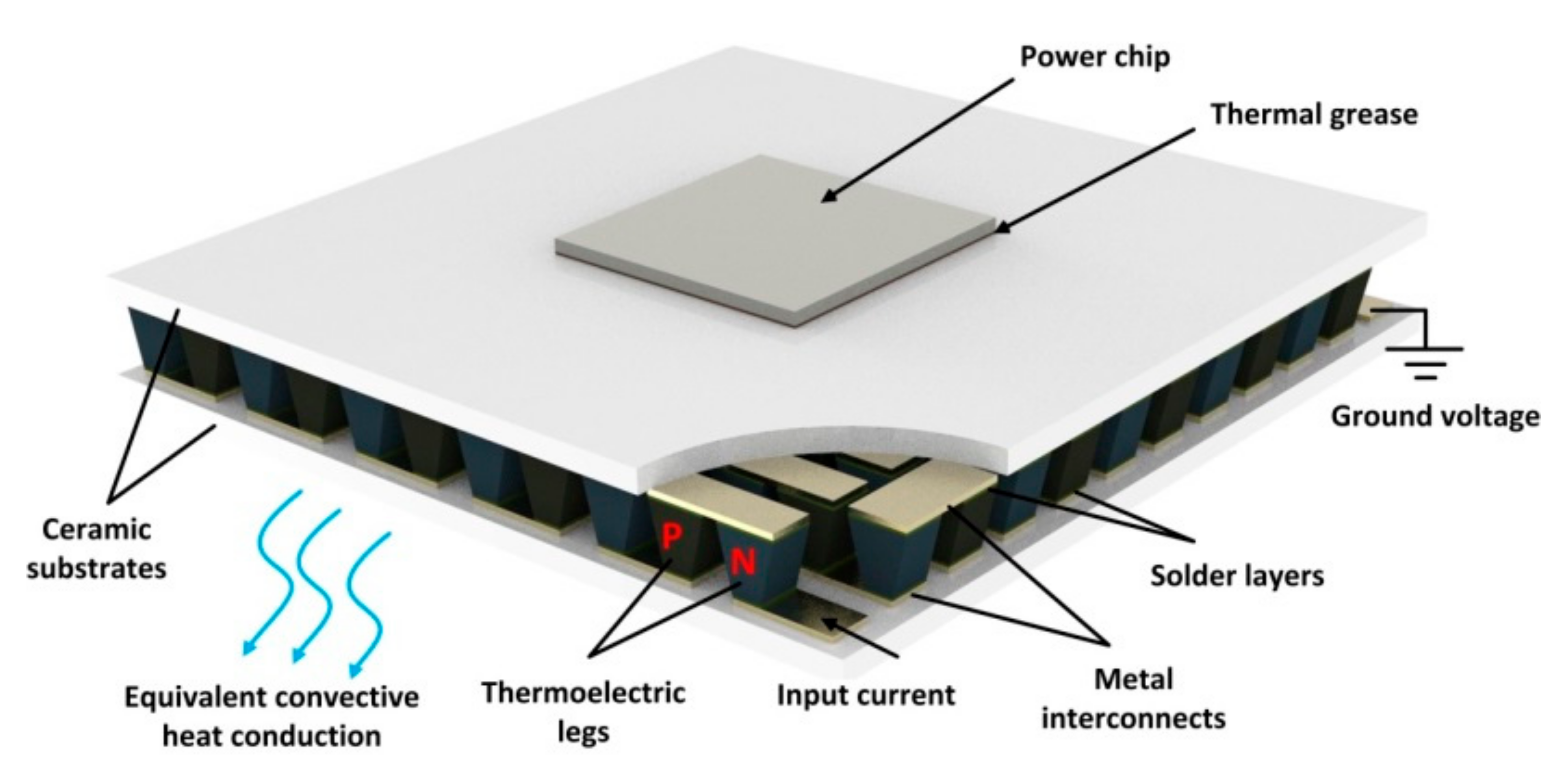
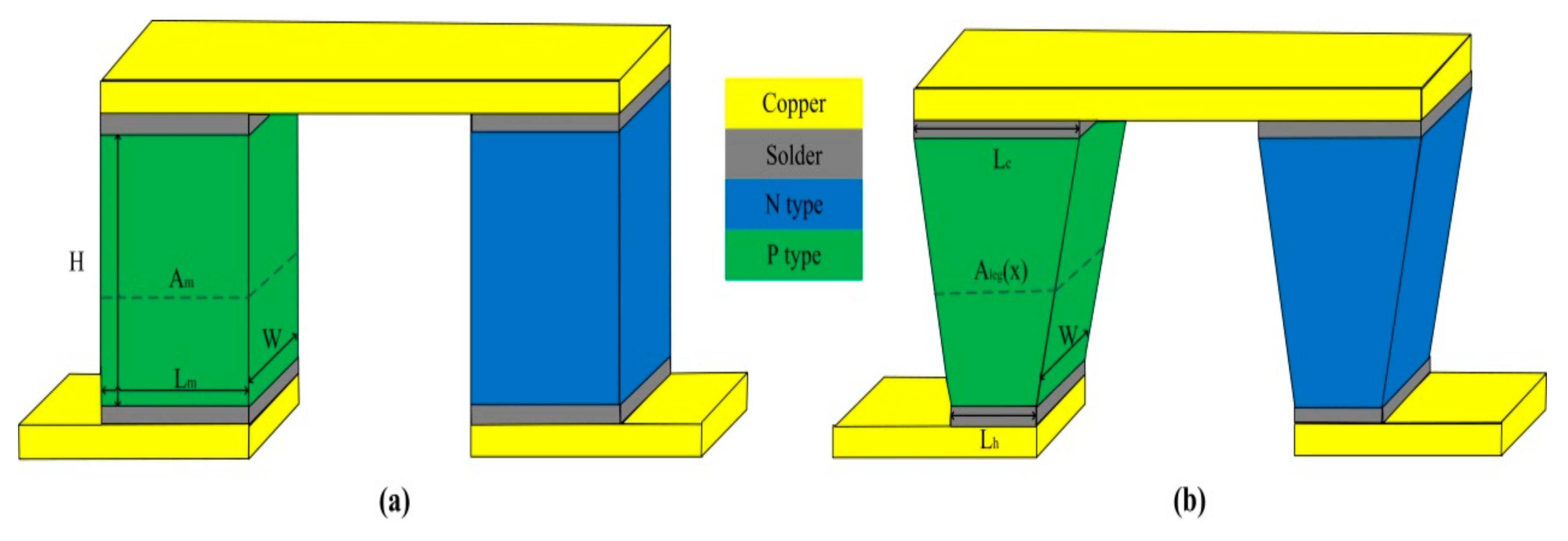
2.1. Physical Model
2.2. Thermo-Physical Properties
2.3. Mathematical Model
2.4. Numerical Model
2.4.1. Mathematical Equations of Thermoelectric Analysis
2.4.2. Mathematical Equations of Thermal Stress Analysis
2.4.3. Boundary Conditions
- Steady state conditions are assumed in this study;
- Apart from the cold side and hot side for the trapezoidal TEC, all lateral surfaces are considered to be adiabatic;
- Electrical and thermal contact resistance are neglected;
- The thermal power of the power chip on the cold side of trapezoidal TEC is set to 5 W;
- The heat sink connected to the hot end of the trapezoidal TEC is assumed to be the equivalent convection heat transfer coefficient, its value is set to 1000 W/(m2 K) to meet the range of forced convection heat conduction for water;
- The cold side and hot side of the trapezoidal TEC are fixed by clamps during thermal stress analysis.
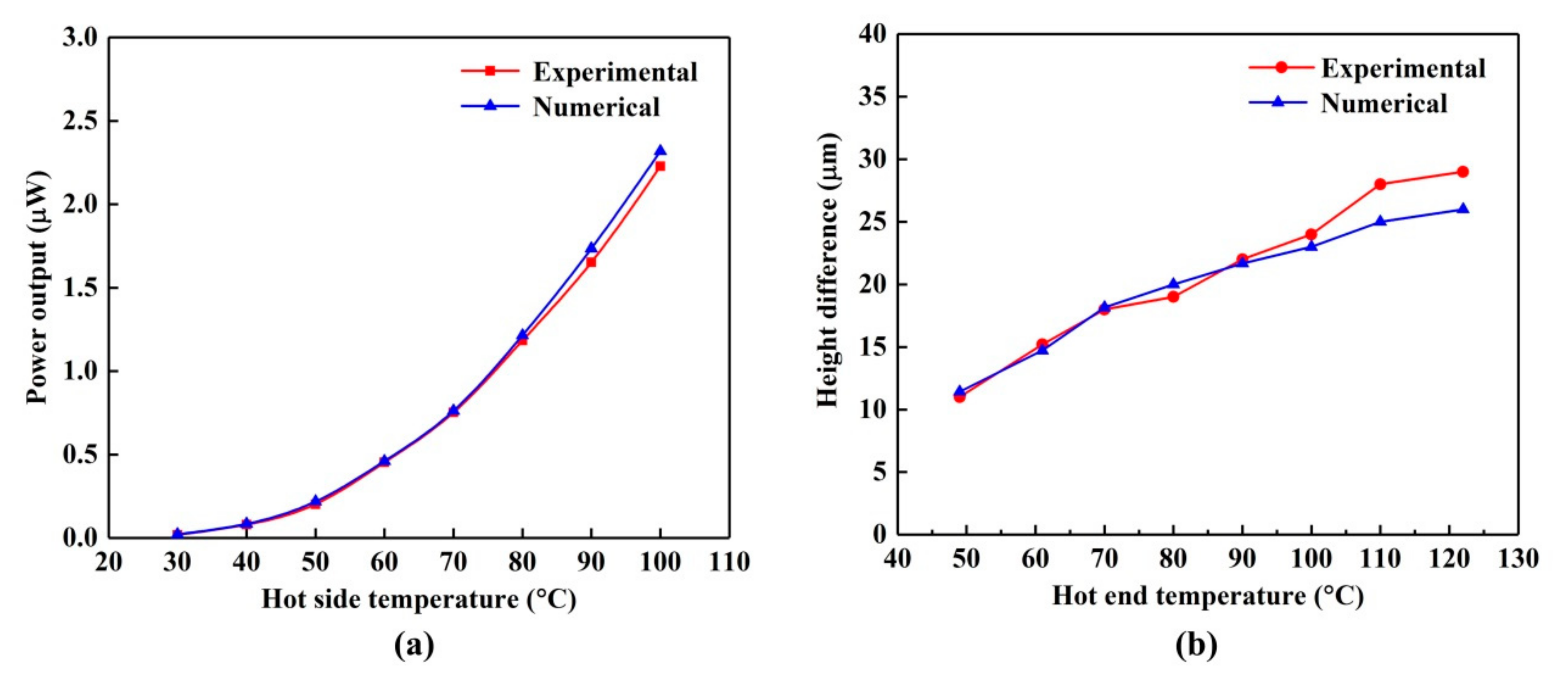
2.4.4. Model Validation
3. Results and Discussion
3.1. Influence of Electrical Current
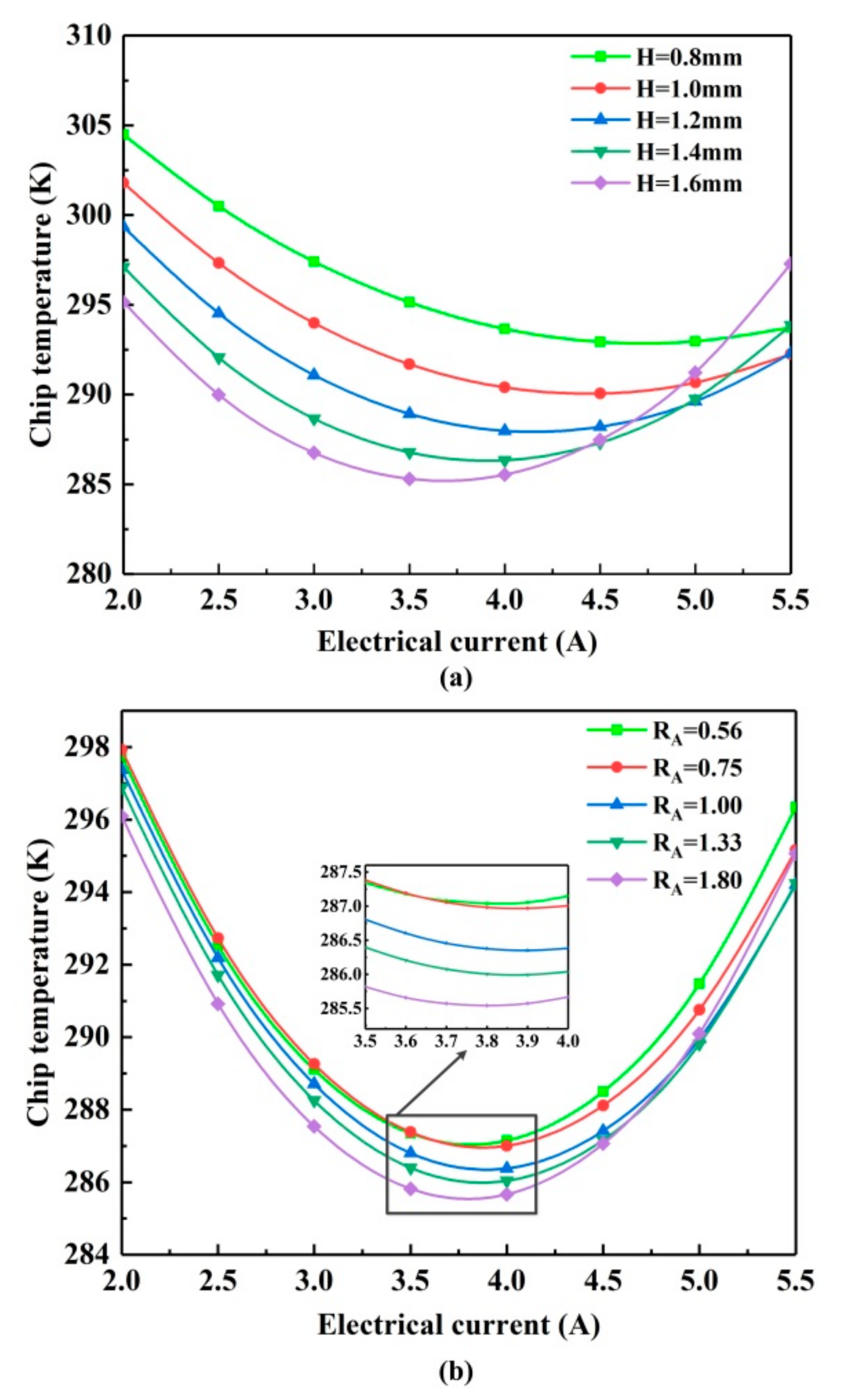
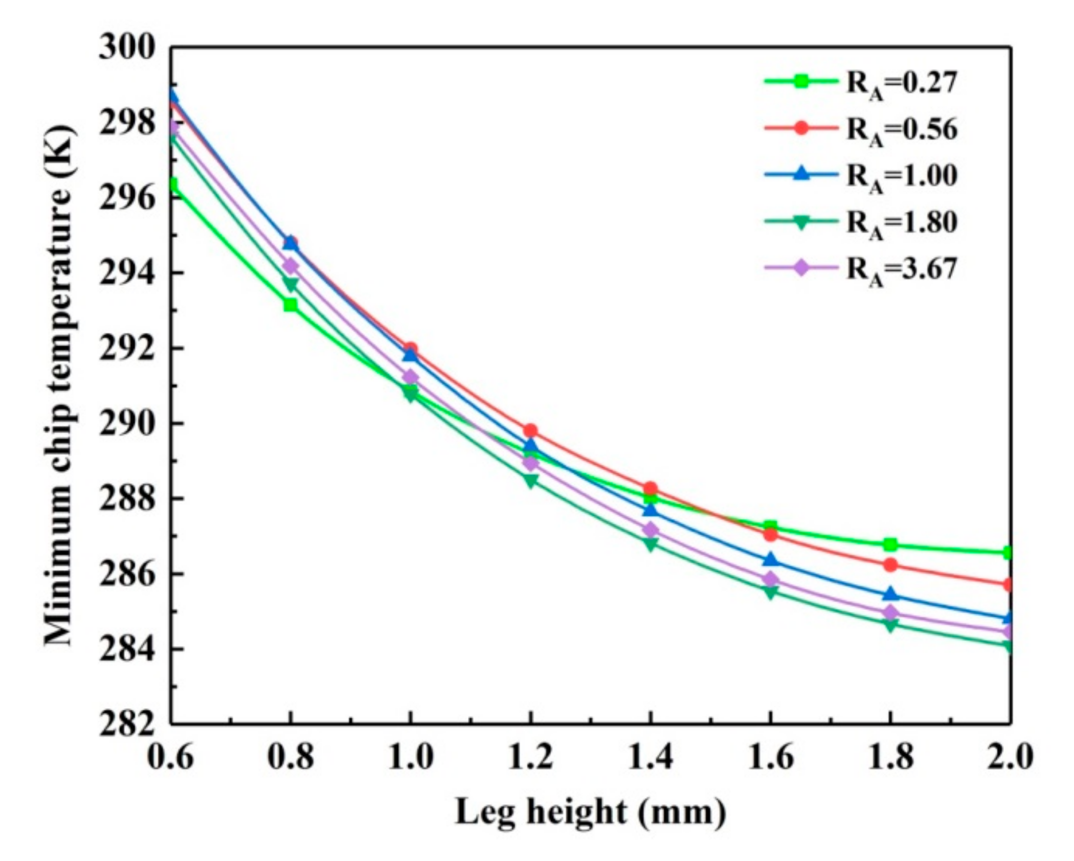
3.2. Influence of Leg Height
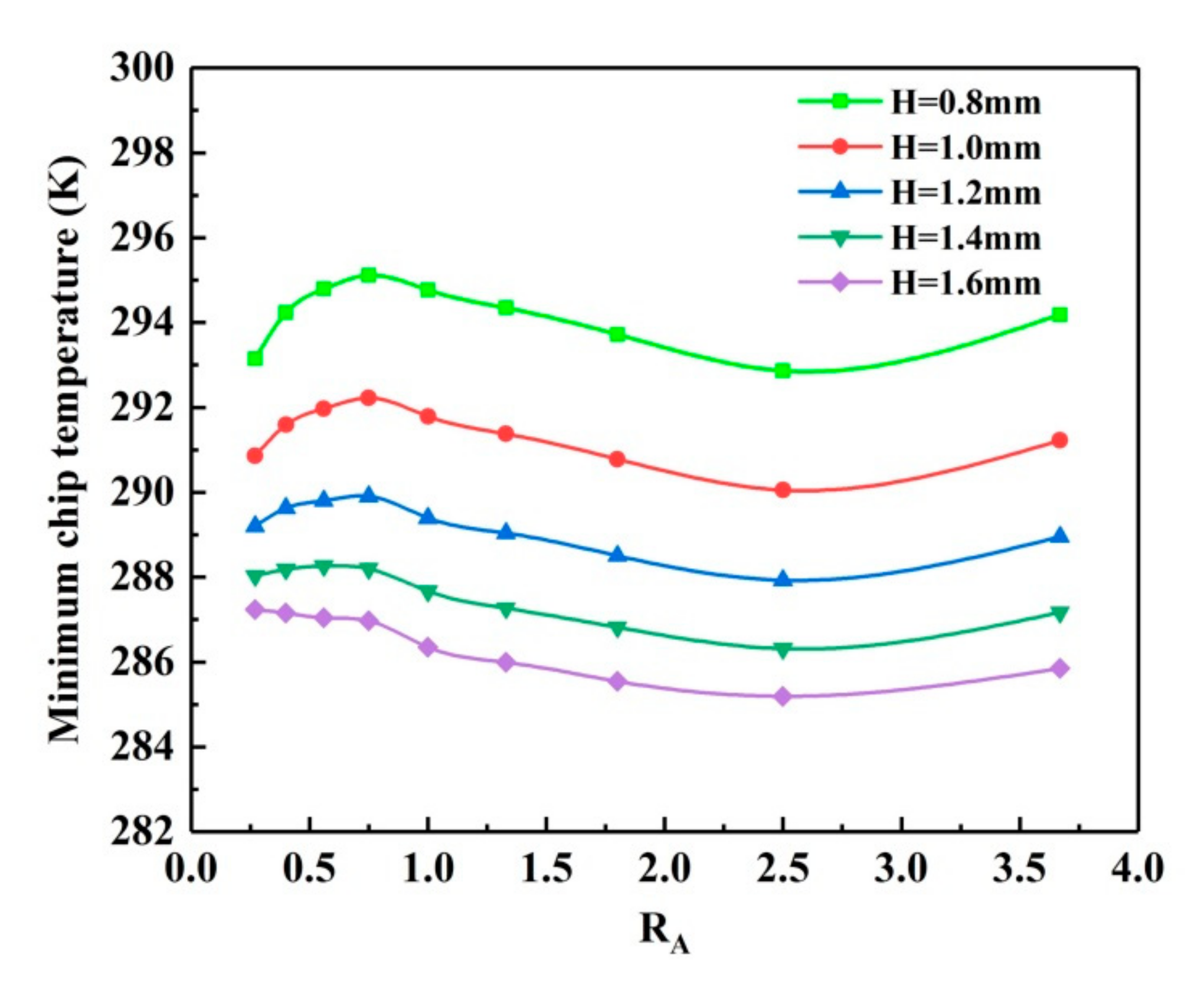
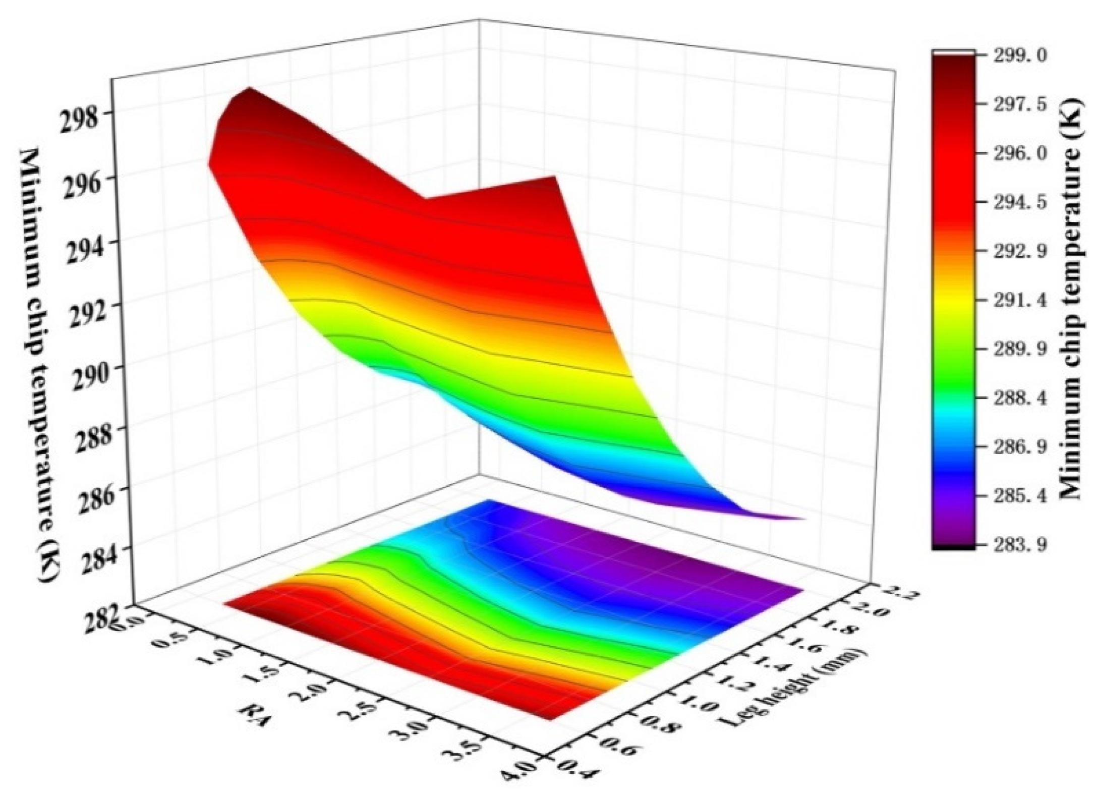
3.3. Influence of Cross-Sectional Area Ratio
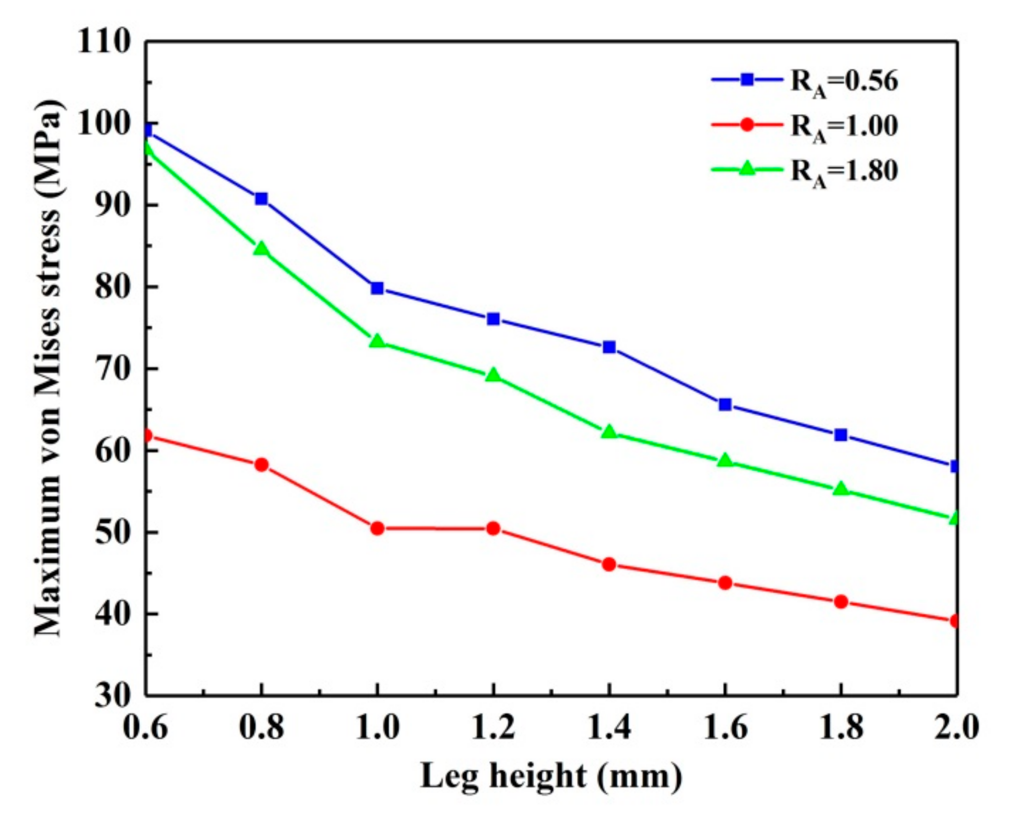
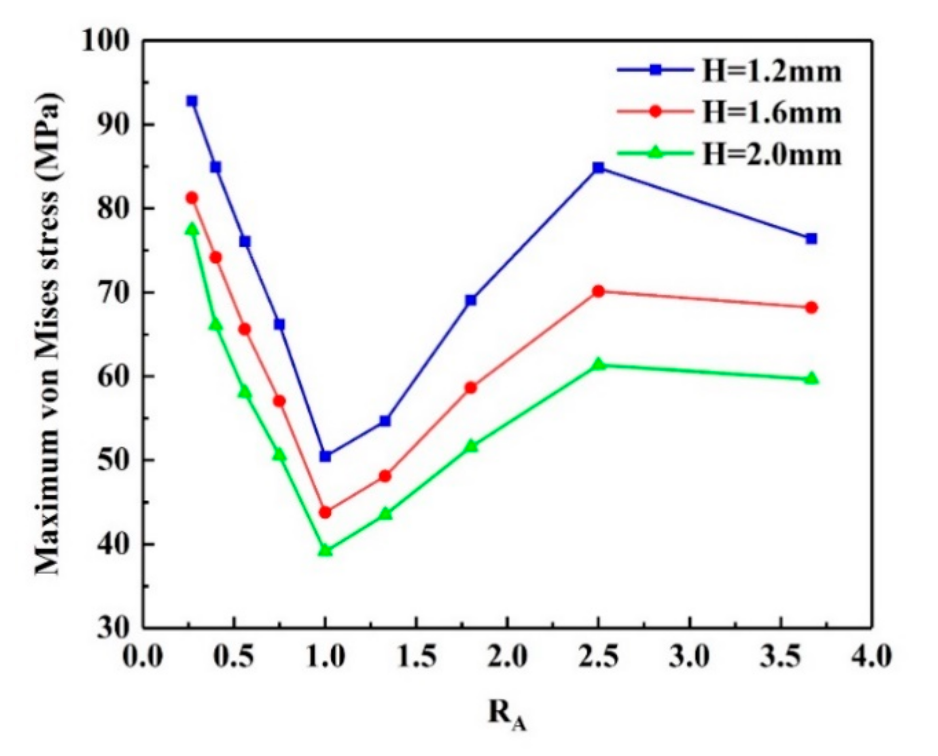
3.4. Thermal Stress Analysis
4. Conclusions
- 1.
- The optimal electrical current corresponding to the trapezoidal-shaped thermoelectric leg under different geometric parameters is different. The optimal electrical current should be used when analyzing the performance and thermal stress of the trapezoidal TEC.
- 2.
- Increasing the thermoelectric leg height simultaneously improves the cooling performance and mechanical reliability of the trapezoidal TEC. For RA = 1.8, the minimum chip temperature decreased by 4.5% and the maximum von Mises stress of the leg decreased by 46.7% as the leg height increased from 0.6 mm to 2.0 mm.
- 3.
- Compared to the rectangular TEC, the variable cross-sectional design for the trapezoidal TEC improves the cooling performance. The minimum chip temperature was reduced by 0.87% under the trapezoidal thermoelectric cooler with optimized geometry.
- 4.
- The maximum von Mises stress for the trapezoidal-shaped leg was greater than that of the rectangular-shaped leg. The maximum von Mises stress of the leg for the trapezoidal thermoelectric cooler with optimal cooling performance increased by 40.1% compared to the original rectangular thermoelectric cooler. Therefore, both the cooling performance and reliability need to be considered at the same time when designing a trapezoidal TEC.
Author Contributions
Funding
Conflicts of Interest
References
- Cai, Y.; Wang, Y.; Liu, D.; Zhao, F.Y. Thermoelectric cooling technology applied in the field of electronic devices: Updated review on the parametric investigations and model developments. Appl. Therm. Eng. 2019, 148, 238–255. [Google Scholar] [CrossRef]
- Sarafraz, M.M.; Pourmehran, O.; Yang, B.; Arjomandi, M. Assessment of the thermal performance of a thermosyphon heat pipe using zirconia-acetone nanofluids. Renew. Energ. 2019, 136, 884–895. [Google Scholar] [CrossRef]
- Sarafraz, M.M.; Yang, B.; Pourmehran, O.; Arjomandi, M.; Ghomashchi, R. Fluid and heat transfer characteristics of aqueous graphene nanoplatelet (GNP) nanofluid in a microchannel. Int. Commum. Heat Mass Transf. 2019, 107, 24–33. [Google Scholar] [CrossRef]
- Pan, M.Q.; Zhong, Y.J. Experimental and numerical investigation of a thermal management system for a Li-ion battery pack using cutting copper fiber sintered skeleton/paraffin composite phase change materials. Int. J. Heat Mass Transf. 2018, 126, 531–543. [Google Scholar] [CrossRef]
- Pourmehran, O.; Sarafraz, M.M.; Rahimi-Gorji, M.; Ganji, D.D. Rheological behaviour of various metal-based nano-fluids between rotating discs: A new insight. J. Taiwan Inst. Chem. E 2018, 88, 37–48. [Google Scholar] [CrossRef]
- Nazari, S.; Ellahi, R.; Sarafraz, M.M.; Safaei, M.R.; Asgari, A.; Akbari, O.A. Numerical study on mixed convection of a non-Newtonian nanofluid with porous media in a two lid-driven square cavity. J. Therm. Anal. Calorim. 2020, 140, 1121–1145. [Google Scholar] [CrossRef]
- Sun, H.N.; Gil, S.U.; Liu, W.; Liu, Z.C. Structure optimization and exergy analysis of a two-stage TEC with two different connections. Energy 2019, 180, 175–191. [Google Scholar] [CrossRef]
- Xu, G.L.; Duan, Y.; Chen, X.T.; Ming, T.Z.; Huang, X.M. Effects of thermal and electrical contact resistances on the performance of a multi-couple thermoelectric cooler with non-ideal heat dissipation. Appl. Therm. Eng. 2020, 169, 114933. [Google Scholar] [CrossRef]
- Simon, J.; Guélou, G.; Srinivasan, B.; Berthebaud, D.; Mori, T.; Maignan, A. Exploring the thermoelectric behavior of spark plasma sintered Fe7-xCoxS8 compounds. J. Alloys Compd. 2020, 819, 152999. [Google Scholar] [CrossRef]
- Srinivasan, B.; Berthebaud, D.; Mori, T. Is LiI a Potential Dopant Candidate to Enhance the Thermoelectric Performance in Sb-Free GeTe Systems? A Prelusive Study. Energies 2020, 13, 643. [Google Scholar] [CrossRef] [Green Version]
- Kishore, R.A.; Kumar, P.; Sanghadasa, M.; Priya, S. Taguchi optimization of bismuth-telluride based thermoelectric cooler. J. Appl. Phys. 2017, 122, 025109. [Google Scholar] [CrossRef]
- Zhu, W.; Deng, Y.; Wang, Y.; Wang, A.L. Finite element analysis of miniature thermoelectric coolers with high cooling performance and short response time. Microelectron. J. 2013, 44, 860–868. [Google Scholar] [CrossRef]
- Huang, Y.X.; Wang, X.D.; Cheng, C.H.; Lin, D.T.W. Geometry optimization of thermoelectric coolers using simplified conjugate-gradient method. Energy 2013, 59, 689–697. [Google Scholar] [CrossRef]
- Abid, M.; Somdalen, R.; Rodrigo, M.S. Design Optimization of a Thermoelectric Cooling Module Using Finite Element Simulations. J. Electron. Mater. 2018, 47, 4845–4854. [Google Scholar] [CrossRef]
- Gong, T.R.; Gao, L.; Wu, Y.J.; Zhang, L.; Yin, S.; Li, J.T.; Ming, T.Z. Numerical simulation on a compact thermoelectric cooler for the optimization design. Appl. Therm. Eng. 2019, 146, 815–825. [Google Scholar] [CrossRef]
- Thimont, Y.; LeBlanc, S. The impact of thermoelectric leg geometries on thermal resistance and power output. J. Appl. Phys. 2019, 126, 095101. [Google Scholar] [CrossRef] [Green Version]
- Siddique, A.M.; Mahmud, S.; Van Heyst, B. Performance comparison between rectangular and trapezoidal-shaped thermoelectric legs manufactured by a dispenser printing technique. Energy 2020, 196, 117089. [Google Scholar] [CrossRef]
- Su, N.; Zhu, P.F.; Pan, Y.H.; Li, F.; Li, B. 3D-printing of shape-controllable thermoelectric devices with enhanced output performance. Energy 2020, 195, 116892. [Google Scholar] [CrossRef]
- Siddique, A.M.; Venkateshwar, K.; Mahmud, S.; Van Heyst, B. Performance analysis of bismuth-antimony-telluride-selenium alloy-based trapezoidal-shaped thermoelectric pallet for a cooling application. Energy Convers. Manag. 2020, 222, 113245. [Google Scholar] [CrossRef]
- Lamba, R.; Kaushik, S.C. Thermodynamic analysis of thermoelectric generator including influence of Thomson effect and leg geometry configuration. Energy Convers. Manag. 2017, 144, 388–398. [Google Scholar] [CrossRef]
- Wang, R.C.; Meng, Z.H.; Luo, D.; Yu, W.; Zhou, W.Q. A Comprehensive Study on X-Type Thermoelectric Generator Modules. J. Electron. Mater. 2020, 49, 4343–4354. [Google Scholar] [CrossRef]
- Trung, N.H.; Toan, N.V.; Ono, T. Flexible thermoelectric power generator with Y-type structure using electrochemical deposition process. Appl. Energy 2018, 210, 467–476. [Google Scholar]
- Lin, S.M.; Yu, J.L. Optimization of a trapezoid-type two-stage Peltier couples for thermoelectric cooling applications. Int. J. Refrig. 2016, 65, 103–110. [Google Scholar] [CrossRef]
- Lv, H.; Wang, X.D.; Wang, T.H.; Cheng, C.H. Improvement of transient supercooling of thermoelectric coolers through variable semiconductor cross-section. Appl. Energy 2016, 164, 501–508. [Google Scholar] [CrossRef]
- Gao, Y.W.; Meng, J.H.; Liu, H.B.; Chen, W.H.; Wang, X.D. Transient supercooling behaviors of a novel two-stage Peltier cooler. Appl. Therm. Eng. 2018, 143, 248–256. [Google Scholar] [CrossRef]
- Qiu, C.S.; Shi, W.K. Comprehensive modeling for optimized design of a thermoelectric cooler with non-constant cross-section: Theoretical considerations. Appl. Therm. Eng. 2020, 176, 115384. [Google Scholar] [CrossRef]
- Lamba, R.; Maikandan, S.; Kaushik, S.C.; Tyagi, S.K. Thermodynamic modelling and performance optimization of trapezoidal thermoelectric cooler using genetic algorithm. Therm. Sci. Eng. Prog. 2018, 6, 236–250. [Google Scholar] [CrossRef]
- Cui, Y.J.; Wang, B.L.; Wang, K.F. Thermally induced vibration and strength failure analysis of thermoelectric generators. Appl. Therm. Eng. 2019, 160, 113991. [Google Scholar] [CrossRef]
- Karri, N.K.; Mo, C. Reliable Thermoelectric Module Design under Opposing Requirements from Structural and Thermoelectric Considerations. J. Electron. Mater. 2018, 47, 3127–3135. [Google Scholar] [CrossRef]
- Wu, Y.J.; Ming, T.Z.; Li, X.H.; Pan, T.; Peng, K.Y.; Luo, X.B. Numerical simulations on the temperature gradient and thermal stress of a thermoelectric power generator. Energy Convers. Manag. 2014, 88, 915–927. [Google Scholar] [CrossRef]
- Jia, X.D.; Gao, Y.W. Estimation of thermoelectric and mechanical performances of segmented thermoelectric generators under optimal operating conditions. Appl. Therm. Eng. 2014, 73, 335–342. [Google Scholar] [CrossRef]
- Al-Merbati, A.S.; Yilbas, B.S.; Sahin, A.Z. Thermodynamics and thermal stress analysis of thermoelectric power generator: Influence of pin geometry on device performance. Appl. Therm. Eng. 2013, 50, 683–692. [Google Scholar] [CrossRef]
- Erturun, U.; Erermis, K.; Mossi, K. Effect of various leg geometries on thermo-mechanical and power generation performance of thermoelectric devices. Appl. Therm. Eng. 2014, 73, 128–141. [Google Scholar] [CrossRef]
- Yilbas, B.S.; Akhtar, S.S.; Sahin, A.Z. Thermal and stress analyses in thermoelectric generator with tapered and rectangular pin configurations. Energy 2016, 114, 52–63. [Google Scholar] [CrossRef]
- Ibeagwu, O.I. Modelling and comprehensive analysis of TEGs with diverse variable leg geometry. Energy 2019, 180, 90–106. [Google Scholar] [CrossRef]
- Wang, W.C.; Chang, Y.L. Experimental Investigation of Thermal Deformation in Thermoelectric Coolers. Strain 2011, 47, 232–237. [Google Scholar] [CrossRef]
- Gong, T.R.; Wu, Y.J.; Gao, L.; Zhang, L.; Li, J.T.; Ming, T.Z. Thermo-mechanical analysis on a compact thermoelectric cooler. Energy 2019, 172, 1211–1224. [Google Scholar] [CrossRef]
- Gong, T.R.; Gao, L.; Wu, Y.J.; Tan, H.S.; Qin, F.; Ming, T.Z.; Li, J.T. Transient thermal stress analysis of a thermoelectric cooler under pulsed thermal loading. Appl. Therm. Eng. 2019, 162, 114240. [Google Scholar] [CrossRef]
- Shittu, S.; Li, G.Q.; Xuan, Q.D.; Zhao, X.D.; Ma, X.L.; Cui, Y. Electrical and mechanical analysis of a segmented solar thermoelectric generator under non-uniform heat flux. Energy 2020, 199, 117433. [Google Scholar] [CrossRef]
- Shen, Z.G.; Liu, X.; Chen, S.; Wu, S.Y.; Xiao, L.; Chen, Z.X. Theoretical analysis on a segmented annular thermoelectric generator. Energy 2018, 157, 297–313. [Google Scholar] [CrossRef]
- Shittu, S.; Li, G.Q.; Zhao, X.D.; Ma, X.L.; Akhlaghi, Y.G.; Ayodele, E. High performance and thermal stress analysis of a segmented annular thermoelectric generator. Energy Convers. Manag. 2019, 184, 180–193. [Google Scholar] [CrossRef]
- Liu, H.B.; Meng, J.H.; Wang, X.D.; Chen, W.H. A new design of solar thermoelectric generator with combination of segmented materials and asymmetrical legs. Energy Convers. Manag. 2018, 175, 11–20. [Google Scholar] [CrossRef]
- Sahin, A.Z.; Yilbas, B.S. The thermoelement as thermoelectric power generator: Effect of leg geometry on the efficiency and power generation. Energy Convers. Manag. 2013, 65, 26–32. [Google Scholar] [CrossRef]
- Shen, L.M.; Zhang, W.S.; Liu, G.Y.; Lu, Q.Q.; Chen, H.X.; Huang, Q.J. Performance enhancement investigation of thermoelectric cooler with segmented configuration. Appl. Therm. Eng. 2020, 168, 114852. [Google Scholar] [CrossRef]
- Yu, J.; Kong, L.; Zhu, Q.S.; Zhu, H.J.; Wang, H.Q.; Guan, J.L.; Yan, Q. Thermal Stress Analysis of a Segmented Thermoelectric Generator under a Pulsed Heat Source. J. Electron. Mater. 2020, 49, 4392–4402. [Google Scholar] [CrossRef]


| Parameter | Value |
|---|---|
| Leg height (mm) | 1.6 |
| Electrode thickness (mm) | 0.2 |
| Solder thickness (mm) | 0.1 |
| Substrate thickness (mm) | 0.8 |
| Cross-section area of the legs (mm2) | 1.4 × 1.4 |
| pitch (mm) | 1.0 |
| Power chip thickness (mm) | 0.4 |
| Thermal grease thickness (mm) | 0.1 |
| Cross-section area of power chip (mm2) | 10 × 10 |
| Material | Thermal Conductivity (W/(m∙K)) | Electrical Conductivity (S/m) | Seebeck Coefficient (V/K) | Density (kg/m3) | Specific Heat Capacity (J/kg·K) | Young’s Modulus (GPa) | Coefficient of Thermal Expansion (1/K) | Poisson’s Ratio |
|---|---|---|---|---|---|---|---|---|
| Ceramic | 25 | 1 × 10⁻¹² | 0 | 3970 | 800 | 380 | 6.5 × 10⁻⁶ | 0.22 |
| Copper | 385 | 5.9 × 10⁷ | 6.5 × 10⁻⁶ | 8930 | 386 | 115 | 1.7 × 10⁻⁵ | 0.31 |
| Solder | 55 | 2 × 10⁷ | 0 | 7240 | 210 | 44.5 | 2.7 × 10⁻⁵ | 0.33 |
| P-Bi2Te3 | - | - | - | 7740 | 154.4 | 65~59 | 0.8 × 10⁻⁵~1.32 × 10⁻⁵ | 0.23 |
| N-Bi2Te3 | - | - | - | 7740 | 154.4 | 65~59 | 0.8 × 10⁻⁵~1.32 × 10⁻⁵ | 0.23 |
| Power chip | 420 | 1 × 10⁻¹⁴ | 0 | 3100 | 800 | 410 | 4 × 10⁻⁶ | 0.14 |
| Thermal grease | 1 | 2.5 × 10⁻¹² | 0 | 1630 | 1450 | 60 | 1.8 × 10⁻⁵ | 0.19 |
| Grid Number | Chip Temperature for I = 2 A (K) | Chip Temperature for I = 3 A (K) | Chip Temperature for I = 4 A (K) | Chip Temperature for I = 5 A (K) |
|---|---|---|---|---|
| 171040 | 332.183 | 322.049 | 318.728 | 321.935 |
| 209655 | 332.224 | 322.091 | 318.762 | 321.961 |
| 266264 | 332.215 | 322.081 | 318.752 | 321.950 |
| RA | 0.27 | 0.4 | 0.56 | 0.75 | 1 | 1.33 | 1.8 | 2.5 | 3.67 |
|---|---|---|---|---|---|---|---|---|---|
| Ac (mm2) | 0.84 | 1.12 | 1.4 | 1.68 | 1.96 | 2.24 | 2.52 | 2.8 | 3.08 |
| Ah (mm2) | 3.08 | 2.8 | 2.52 | 2.24 | 1.96 | 1.68 | 1.4 | 1.12 | 0.84 |
Publisher’s Note: MDPI stays neutral with regard to jurisdictional claims in published maps and institutional affiliations. |
© 2020 by the authors. Licensee MDPI, Basel, Switzerland. This article is an open access article distributed under the terms and conditions of the Creative Commons Attribution (CC BY) license (http://creativecommons.org/licenses/by/4.0/).
Share and Cite
Lu, T.; Li, Y.; Zhang, J.; Ning, P.; Niu, P. Cooling and Mechanical Performance Analysis of a Trapezoidal Thermoelectric Cooler with Variable Cross-Section. Energies 2020, 13, 6070. https://doi.org/10.3390/en13226070
Lu T, Li Y, Zhang J, Ning P, Niu P. Cooling and Mechanical Performance Analysis of a Trapezoidal Thermoelectric Cooler with Variable Cross-Section. Energies. 2020; 13(22):6070. https://doi.org/10.3390/en13226070
Chicago/Turabian StyleLu, Tianbo, Yuqiang Li, Jianxin Zhang, Pingfan Ning, and Pingjuan Niu. 2020. "Cooling and Mechanical Performance Analysis of a Trapezoidal Thermoelectric Cooler with Variable Cross-Section" Energies 13, no. 22: 6070. https://doi.org/10.3390/en13226070