Article

A Dynamic Multi-Cell FCL to Improve the Fault Ride through Capability of DFIG-Based Wind Farms

1
Department of Electrical and Computer Engineering, University of Semnan, Semnan 3535168641, Iran
2
Golestan Province Distribution Electrical Company, Gorgan 517212, Iran
3
Department of Electrical Engineering, Abhar Branch, Islamic Azad University, Abhar 1584743311, Iran
4
Future Technology Research Center, National Yunlin University of Science and Technology, 123 University Road, Section 3, Douliou, Yunlin 64002, Taiwan
5
Electrical and Computer Engineering Department, University of Louisiana at Lafayette, P.O. Box 43890, Lafayette, LA 70504, USA
*
Author to whom correspondence should be addressed.
Energies 2020, 13(22), 6071; https://doi.org/10.3390/en13226071
Submission received: 21 October 2020 / Revised: 9 November 2020 / Accepted: 17 November 2020 / Published: 20 November 2020

Abstract

:
Endowing wind farms (WFs) with fault ride through (FRT) capability is crucial to their continuous availability under various operating conditions. This paper proposes a dynamic adaptive multi-cell fault current limiter (MCFCL) topology to enhance the FRT capability of grid connected WFs. The proposed MCFCL consists of one transient cell (TC) and multi resistive cells (RCs) directly connected to the grid’s high voltage without using any series injection transformers nor any series connection of semiconductor switches. The transient cell of the MCFCL includes two transient limiting reactors (TLRs) to mitigate the transient fault current and limit the rate of change of the currents of the semiconductor switches during fault occurrence. The number of RCs in the MCFCL is determined based on voltage sag level. These latter are inserted in the fault path to provide an adaptive voltage sag compensation mechanism according to the voltage sag level. Assessment of the MCFCL under various sag conditions, showed that the MCFCL is able to effectively compensate for a wide range of voltage sags without any over voltage at the WF’s terminal. Comparison analysis with the conventional single-cell bridge-type FCL (SBFCL) showed the superior performance of the proposed MCFCL.

1. Introduction

To facilitate the integration of an increased number of wind turbines into the power grid, many countries have adopted new grid codes [1]. These latter aim at specifying the electrical performance that generation units must comply with in order to ensure the safe and reliable operation of power grids. Fault ride-through (FRT) capability which aims at mitigating the adverse effects of grid faults is among the aspects covered by grid codes [1,2]. This capability helps to WFs to remain connected to the grid for a certain time, under faulty conditions [2]. This measure prevents the widespread tripping of WTs due to grid disturbances and thwarts local or system wide instabilities [1,2].
Doubly fed induction generators (DFIGs) are widely used in modern WTs because of their variable speed operation, partially rated power converters and ability to decouple the control of the active and reactive powers [3]. A major drawback of DFIGs, however, is their high sensitivity to grid disturbances such as short circuit faults and voltage sags or short duration voltage variations. These latter may lead to high transient over-currents in the rotor circuit and over-voltage in the DC link capacitor [3]. This problem can either be mitigated using software [4,5,6] or hardware [7,8,9,10,11,12,13,14,15,16,17,18,19,20] approaches. The software-type solutions are based on modifications of the DFIG converters, especially the rotor side converter (RSC). Among the drawbacks of the software-based approaches are limited RSC capacity and capacitor voltage limitation in severe voltage sags. The above-mentioned problems can be overcome using hardware approaches [3]. These latter encompass (1) shunt flexible ac transmission systems (FACTS) controllers which include STATCOM devices [7]; (2) series hardware schemes, which include dynamic voltage restorers (DVR) [8], unified inter-phase power controllers (UIPC) [9], and series braking resistors (SBR) [10]; (3) energy storage systems (ESS) [11]; and (4) fault current limiters (FCLs) [12,13,14,15,16,17,18,19,20].
Though hardware schemes such as static synchronous compensators (STATCOM), dynamic voltage restorers (DVR), unified interphase power controllers (UIPC) and energy storage systems (ESS) are reliable interfaces that can fulfil the FRT requirements of WFs; they require high capacity and accordingly high-cost power converters, thus making these solutions costly and impractical. Among the hardware schemes, FCLs were found to be effective FRT protection schemes [3,4]. Various FCL technologies have been proposed and developed in the literature to mitigate fault currents. They are generally classified into superconducting FCLs (SFCLs) [12,13], and solid-state FCLs (SSFCLs) [14,15]. Employing SFCLs in WFs provides a feasible interconnection mechanism to enhance FRT. However, they require high-cost superconducting materials and cooling systems when used in high voltage systems [14].
Recently, the bridge-type FCLs (BFCLs), which are classified as SSFCLs are receiving more attention as an effective measure to meet the WF requirements [15]. Though various BFCL topologies have been proposed and documented in the literature, they were reported to be used for FRT enhancement for the first time in [14]. In this topology, the discharging resistor (DR) was located in the DC side and the DR was used to consume the excess active power of the WF generators and improve their FRT capability. Firouzi et al. proposed a sliding mode controller-Based BFCL for Fault Ride-Through Performance Enhancement of DFIG-Based Wind in [15]. The authors further proposed a transformer-type BFCL with multi-resistors instead of a single DR to improve the DFIG FRT performance in [16]. Using a three-phase coupling transformer, however, was shown to reduce the efficiency of the BFCL under asymmetrical faults and increase its cost. The DR in the DC side was transferred into the AC side and implemented in parallel with the BFCL in [17]. Hossain used a BFCL with a series inductor and resistor to improve the transient stability of DFIG-based WTss [18]. A series capacitor and a resistor were used in [19], as limiting impedance to support the interconnection point voltage by supplying the necessary reactive power. Kartijkolaie et al. proposed to place the resistor in the DC side of the BFCLto consume the DFIG’s active power and improve its FRT capability [20].
All the above mentioned BFCL-based techniques are based on single-cell FCLs. Their components and limiting impedance are designed considering the system voltage level and worst voltage sag condition, respectively. Additionally, they place the limiting impedance in series with the faulty line path, which can cause destructive over voltage at the WF’s interconnection point for lower voltage sag level. Also, the limiting impedance switching in the single-cell BFCL (SBFCL) increases the failure rate and voltage stress of the semiconductor switches.
To mitigate the above problems, we propose in this paper a dynamic multi-cell FCL (MCFCL) topology. Its main contributions are as follows:
  • A multi-cell FCL that has a resistor in each cell and is directly connected to the power grid without using the series transformer, thus reducing the volume and cost of the MCFCL.
  • A FCL topology that puts the suitable number of cells in the fault path in accordance with the voltage sag level, thus providing an adaptive voltage sag compensation mechanism.
  • A design that is able to effectively mitigate voltage sag conditions ranging from low to severe and prevent the occurrence of over-voltages in the WF terminals.
The remainder of the paper is organized as follows. The proposed MCFCL power circuit is detailed in Section 2. An analytical study of the proposed topography is provided in Section 3. The proposed topology is implemented to a DFIG-based WF and its performance is assessed under various voltage sag conditions in Section 4. Some concluding remarks are provided in Section 5.

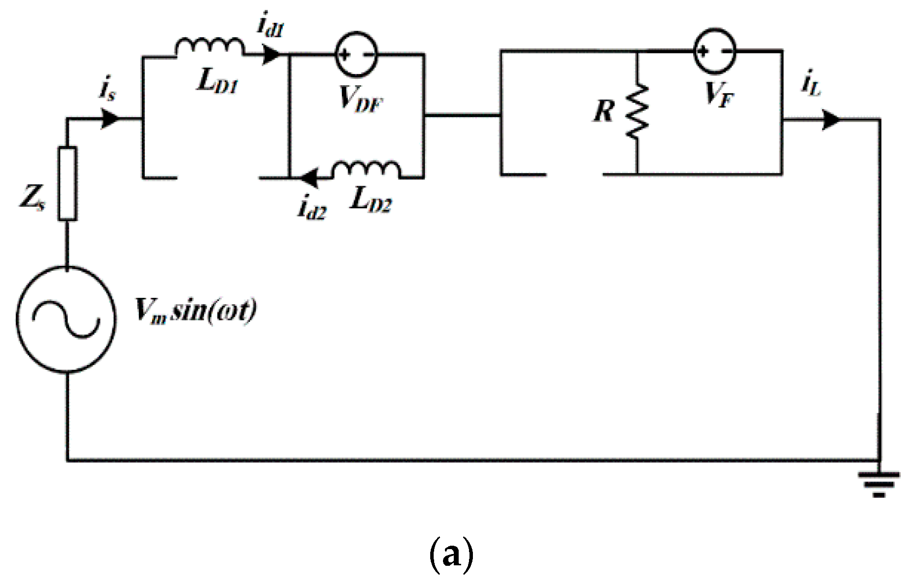
2. Proposed Multi-Cell Fault Current Limiter (MCFCL) Topology

The proposed MCFCL configuration is illustrated in Figure 1a. The MCFCL consists of two main parts, including a transient cell (TC) and n resistive cells (RC) coupled in series arrangement to meet high voltage operation requirements. The TC of the MCFCL include two diodes (D1 and D2) and two transient limiting reactors (TLRs) to limit the transient fault current at the fault occurrence instant. Each RC of the MCFCL consists of two gate-turn off (GTO) semiconductor switches and one limiting resistor.

2.1. MCFCL Operation

The basic operating principle of the MCFCL is divided into normal and faulty operating conditions. Under normal conditions, all the RCs’ GTO switches are closed. Therefore, the limiting resistors of RCs (R1–Rn) are bypassed. The AC line current (iL) passes through the D1-LD1-T11-T1n path and charges the LD1 to the peak value of the current iL. Also, for the negative half cycle of operation, the current iL flows through the D2-LD2-T21-T2n path and charges the LD2 to the peak value of the line current. Figure 1b illustrates the line current flow path under normal conditions for the positive and negative half cycle of operation, respectively. After several cycles, the LD1 and LD2 act as a DC current source. Thus, diodes D1 and D2 are freewheeling and result in a zero voltage drop under normal conditions.
Note however, that under normal conditions, the flowing line current from TLRs and the semiconductor switches results in some power and voltage losses. However, the latter can be ignored in HV systems. When a short circuit fault occurs in the downstream of the MCFCL, the raising rate of the fault current is suppressed by the TLRs of the TC. Then, considering the coupling voltage level; the MCFCL control system will turn off the GTO switches. Therefore, the MCFCL inserts the combinational of limiting resistors according to Table 1, in fault path to restrict the fault current and compensate the voltage sag at the acceptable level. Figure 1c represents the fault current path under faulty operating conditions for the state S1 according to Table 1.
S1–Sn represent the pair GTO switches’ states of each cell. 1 and 0 represent the ON and OFF states of GTO switches, respectively. Also, V T m a x represents the maximum acceptable voltage of each cell. VPCC and VTh are the measured coupling voltage and the threshold value. After fault period, the coupling voltage starts to recover to pre-fault level. Once the coupling voltage exceeds the threshold value, the semiconductor switches are closed with sequenced arrangements.

2.2. MCFCL Control System

The control system of the MCFCL is illustrated in Figure 1d. Note that the grid coupling voltage succeeding the MCFCL location is used to detect the fault and control the MCFCL operation. First, the voltage at coupling point (VPCC) and the threshold value (VTh) are compared. If VPCC < VTh, the adaptive control circuit detects the fault. Following this, the control system determines the suitable number of cells, which should be inserted in fault path according to Table 1. When the fault is cleared, the VPCC return back to the pre-fault voltage. When the VPCC becomes greater than the VTh, the MCFCL control circuit opens the GTO switches with sequenced arrangements, respectively.

2.3. Procedure to Determine the Number of MCFCL Cells

The number of MCFCL cells is selected based on the voltage rating of the semiconductor switches of each RC. The maximum acceptable voltage of each cell is represented by   V T m a x , which is the voltage rating of each GTO switch in each cell. The maximum voltage drop on each cell is obtained by:
V m = V g n R + Z g
where Vg and Zg represent the grid voltage and impedance, respectively. To ensure that the voltage drop of each cell is within acceptable ranges, the following inequality: V T m a x > V m should be satisfied. Hence, Equation (1) can be re-written as follows:
V T m a x > V g n R + Z g
The number of cells is obtained from (2) as follows:
n > V g V T m a x Z g R V T m a x

3. Analytical Study of the Proposed MCFCL Topology

The configuration of a single phase MCFCL is illustrated in Figure 2a. To simplify the analysis, we consider a MCFCL with two cells, including one TC and one RC, which are located between the power source and the load. Vs and Zs represent the voltage and impedance source, respectively. ZL represents the sum of the load and line impedance in this system. VD and VF are the diodes and GTO switches forward voltages, respectively. Based on the grid operation condition, the MCFCL is divided into two conditions: normal and faulty.
Figure 2b shows the MCFCL performance under both normal and faulty conditions. Under normal conditions, both TLRs currents (id1 and id2) are charged to the positive and negative peak values of line current, respectively. Considering V = L di/dt, the voltage drop on these reactors is low and has no effect on the system performance in this case. The MCFCL operation under faulty condition is represented by periods P1–P4. When the short circuit fault occurs at t = t0, the line currents (iL) and id1 start to increase. The period P1 (t0 < t < t1), represents the MCFCL performance under this condition. Figure 3a represents the equivalent power circuit of the MCFCL for the period P1. Note that during P1, the line current (iL) flows through the D1-LD1-T1 path and charges the DC reactor (LD1). The line current can be expressed by:
V m sin ( ω t ) = L d i L d t + R i L + V D + V F
where R = rd1 + Rs and L = LD1+Ls.
Solving (4), yields the following expression for iL:
i L ( t ) = [ i 0 V m | Z | sin ( ω t 0 φ ) + V D + V F R ] e R L ( t t 0 ) + V m | Z | sin ( ω t φ ) V D + V F R
At t = t2, the control system of the MCFCL detects the fault and turns the GTO switches (T1 and T2) off. The period P2 (t1 < t < t2), represents the MCFCL performance under this condition.
Figure 3b represents the equivalent power circuit of the MCFCL for the period P2. Note that during P2, the current iL is less than its counterpart id1 and the diodes D1 and D2 are in freewheeling state. Considering Figure 3b, the line current is derived as follows:
V m sin ( ω t ) = L d i L d t + R i L
Using (6), we can express the current iL as follows:
i L ( t ) = [ i 1 V m | Z | sin ( ω t 1 φ ) ]
where R = Rs + R and L = Ls. In period P3 (t2 < t < t3), the iL flows through D2-LD2-R path and charges the DC reactor (LD2). Figure 3c represents the equivalent power circuit of the MCFCL for the period P3. The voltage equation in this period is expressed by:
V m sin ( ω t ) = L d i L d t + R i L + V D
Considering (8), the line current is expressed by:
i L ( t ) = [ i 0 V m | Z | sin ( ω t 0 φ ) + V D R ] e R L ( t t 2 ) + V m | Z | sin ( ω t φ ) V D R
where R = rd1 + Rs + R and L = LD1 + Ls. In period P4 (t2 < t < t3), the iL is less than the id2 and the diodes D1 and D2 are freewheeling state. Note that the equivalent power circuit of the MCFCL for period P4 is the same as the one depicted in Figure 3b. Accordingly, the line current equation in this period is expressed using Equation (7).

4. Implementation to a DFIG-Based WF

To assess the performance of the proposed MCFCL topology, we implemented it to the single line diagram depicted in Figure 4a and simulated it using PSCAD/EMTDC software. The simulated WF is connected to the grid through the MCFCL and a 0.7 kV/20 kV transformer. A 20 MW aggregated DFIG-type WT is used to model the WF. Three short circuit faults with different fault impedances are considered to assess the performance of the MCFCL under three voltage sag ranges. Additionally, a comparison analysis with a SBFCL scheme [17] is carried over. In this case we swapped the MCFCL in the system shown in Figure 4a by a SBFCL and compared their performance. The values of RD = 30 Ω and LD = 10 mH are considered in this study. Figure 4b represents the SBFCL power circuit. The parameters of the system under study are provided in Table 2. The dynamics of the wind turbine, DFIG, and its control system are briefly described in the next section.

4.1. DFIG-Based Wind Turbine Model

The mechanical power (Pm) of the wind turbine can be expressed as [21,22]:
P m = 0.5   ρ π R 2 C p ( λ , β ) v w 3
where Pm (10) P w t represents the mechanical power extracted from the wind energy, ρ, vw and λ are the air density, the wind speed, and the tip speed ratio, respectively. R is the blade radius, and CP (β, λ) as follows:
C p ( λ , θ ) = 0.22 ( 116 λ c 0.4 β 5 ) e 12.5 λ c
λ c = ( 1 1 λ + 0.08 β 0.035 β 3 1 )
The drive train system is modelled using the two-mass system detailed in [21].
Figure 4c shows the DFIG connected to the WT. The RSC and grid side converter (GSC) control systems are also depicted in this figure. The DFIG stator and rotor power circuit voltage and flux relations in the d-q synchronous reference frame are expressed by the following Equations (5) and (6):
V q s = R s   i q s + d φ q s d t ω s φ d s
V d s = R s   i d s + d φ d s d t ω s φ q s
V d r = R r   i d r + d φ d r d t ( ω s ω r ) φ q r
V q r = R r   i q r + d φ q r d t ( ω s ω r ) φ d r
λ q s = L s   i q s + L m   i q s
λ d s = L s   i d s + L m   i d s  
λ q r = L s   i q r + L m   i q r
λ d r = L s   i d r + L m   i d r
Indices s, r, q and d represent the stator, rotor, q-axis and d-axis components of stator and rotor voltage and flux. Lm is the magnetizing inductance. The RSC of the DFIG controls the output active and reactive power. Also, the GSC of the DFIG controls the DC link capacitor voltage and the grid coupling voltage (VPCC). Additional details concerning the DFIG control system can be found in [5,6].

4.2. Simulation Results

To assess the performance of the proposed FRT scheme, we apply three short circuit faults with different fault impedances to the PCC bus at t = 5 s for 150 ms as shown in Figure 4a. In these conditions the PCC voltage drops to 0.01 pu, 0.35 pu and 0.75 pu, respectively. This enables us to analyze the performance of the proposed SBFCL scheme under low, medium, and severe voltage sag conditions, respectively.
The SBFCL resistance is RD = 30 Ω and each RC resistance of the MCFCL is R = 10 Ω. The wind speed is considered 14 m/s in this study. Considering system voltage, the MCFCL has four cells, include one TC and three RCs. Also, the voltage sag is divided into three range as demonstrated in Table 3. The switching states and voltage sag ranges are represented as Table 3. S1–S3 represents the pair GTO switches states of RC1–RC3 cell. Simulations are performed as follows:
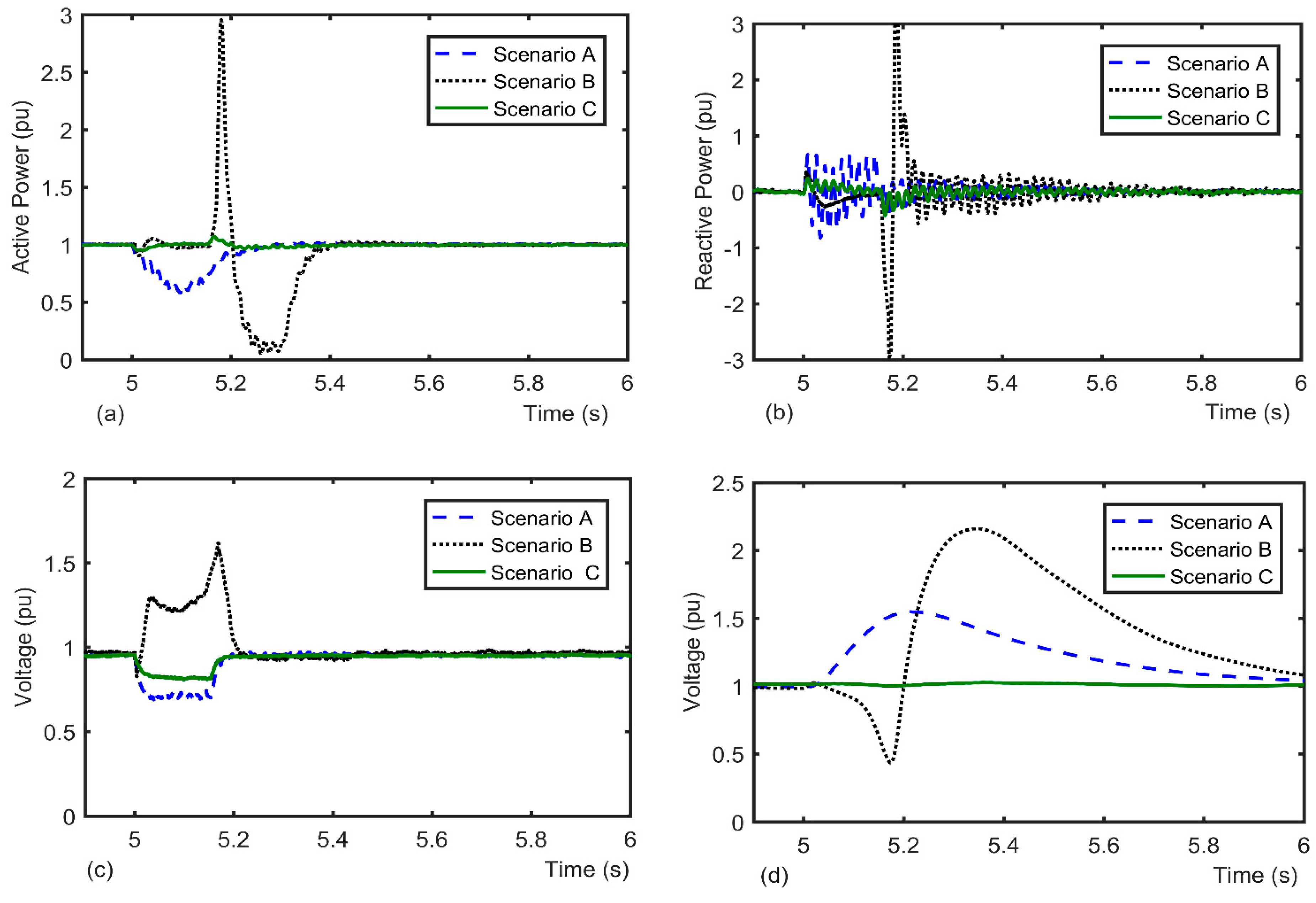
  • - Scenario A: No FRT devices.
  • - Scenario B: Using the SBFCL.
  • - Scenario C: Using the MCFCL.

4.2.1. Low Voltage Sag Condition

In this condition, the fault resistance is set to be Rf = 0.5 Ω, which results in a 0.25 voltage sag at PCC. The conventional SBFCL inserts the RD = 30 Ω in the fault path. However, the MCFCL control circuit turns off the S1 and puts the R = 10 Ω in series with line in scenario C, considering Table 2. Figure 5 demonstrates the MCFCL performance for this condition.
It can be observed from Figure 5a, that the output active power from WF drops to 0.55 pu for scenario A. In scenario B, the active power remains constant during fault occurrence, however; it’s post-fault dynamics show a sharp increase to 3 pu followed by a sudden decrease to near zero, which is harmful for the generator. However, scenario C reveals that using the MCFCL results in lower oscillations in the active power during the fault period and after fault clearance, which provides faster stabilization under faulty conditions. Figure 5b depicts the dynamics of the WF’s reactive power. Note noticeable fluctuations of the WF’s reactive power during post-fault in scenario B. However, with the MCFCL in scenario C, the reactive power fluctuations are lowest, and it quickly returns back to its pre-fault value. Figure 5c shows the dynamics of the terminal voltage for three scenarios under low voltage condition. Considering this figure, the terminal voltage drops to 0.75 pu in scenario A. In scenario B, it raises to 1.5 pu and the DFIG stator experiences transient over-voltage. However, in scenario C, the terminal voltage is 0.9 pu and remains in acceptable range by using the MCFCL.
Figure 5d shows the DC link voltage of DFIG. Considering this figure, it increases to 1.5 pu in this condition for scenario A. In scenario B, it gradually decreases during fault period and then raises to 2.2 pu after fault clearance. However, by using the MCFCL, the DC link voltage remains constant.

4.2.2. Medium Voltage Sag Condition

For this condition, the fault resistance is decreased, and the PCC voltage is decreased to 0.35 pu. The control circuit of the MCFCL opens switches S1 and S2 to insert two cells resistance in the fault path in scenario C, considering Table 2. Figure 6 shows the MCFCL performance for this condition. Figure 6a shows the output active power from WF for this voltage sag level. In this voltage sag level, the output active power from WF drops to 0.15 pu for scenario A. In scenario B, the active power in fault period remains constant, however; it increases to 2.5 pu and then drops after fault period. However, the MCFCL provide the lowest active power fluctuation during and after fault. Figure 6b shows the WF reactive power. Considering this figure, the MCFCL in scenario C has the lowest reactive power fluctuation. Figure 6c shows the terminal voltage for three scenarios in this condition. In scenario A, the terminal voltage drops to 0.4 pu. In scenario B, the terminal voltage raises to 1.2 pu during fault period in this condition. But, in scenario C, it is 0.9 pu and remains in acceptable range by using the MCFCL. Figure 6d shows the DC link voltage for all scenarios. It increases to 2 pu in scenario A. In scenario B, the DC link voltage increases after fault clearance to 1.5 pu and then recovers to its pre-fault value. However, in scenario C, it remains constant during and after fault.

4.2.3. Severe Voltage Sag Condition

Figure 7 depicts the MCFCL performance under severe voltage sag condition for the above mentioned three scenarios. In this condition, the control circuit of the MCFCL opens S1, S2, and S3 and inserts three RCs resistances in series with a line like the SBFCL.
Figure 7a–d present the active power, reactive power and terminal and DC link voltages responses to this severe voltage sag condition. It can be seen from these figures that both MCFCL and SBFCL have similar responses in terms of voltage sag, active power drop, reactive power oscillations, and DC link overvoltage under this condition.
Based on the above results, we can confirm that:
  • Using the SBFCL produces high transient over voltage under low and medium voltage sag conditions, which is harmful for the DFIG under short circuit fault current.
  • The proposed MCFCL scheme is able to properly mitigate a wide range of voltage sag levels without producing any transient over voltage.
  • The MCFCL outperforms the SBFCL in terms of FRT performance and transient over-voltage under medium and low voltage sag levels.
  • Response and performance of both SBFCL and MCFCL are the same under severe voltage sag levels.

5. Conclusions

This paper proposed a novel MCFCL topology to mitigate voltage sags and facilitate the integration of DFIG-based WFs into the high voltage power grid. The proposed scheme includes one TC and multiple RCs directly connected to the grid without using the series transformer, which reduces the cost and volume of the MCFCL. It also inserts a suitable number of RCs in the fault path to provide an adaptive voltage sag compensation mechanism in accordance with the voltage sag level. Assessment of the proposed approach under various sag conditions, showed that the MCFCL is able to effectively compensate for a wide range of voltage sags and prevent the occurrence of over-voltages in the WF terminal. A major advantage of the proposed MCFCL scheme is its ability to insert a suitable number of cells in the fault path to provide the adequate voltage sag compensation in accordance with the severity of the voltage sag. A comparison analysis with the conventional single-cell bridge-type FCL (SBFCL) showed that, although the performance of the MCFCL is similar to that of SBFCL under severe voltage sag conditions, it outperforms the latter in terms of FRT capability transient over-voltage under lower and medium voltage sag levels.

Author Contributions

Conceptualization, investigation, and writing—original draft preparation, M.F., H.S.K. and M.R.S.; writing—review & editing and supervision, S.M. and A.F. All authors have read and agreed to the published version of the manuscript.

Funding

The authors received no financial support for the research, authorship, and/or publication of this article.

Conflicts of Interest

The authors declare that they have no conflict of interest.

References

  1. Tong, N.; Lin, X.; Li, Z.; Fang, J.; Zhuo, Y.; Sui, Q.; Jin, N.; Chen, Z.; Muradov, N. Coordinated Sequential Control of Individual Generators for Large-Scale DFIG-Based Wind Farms. IEEE Trans. Sustain. Energy 2019, 11, 1679–1692. [Google Scholar] [CrossRef]
  2. Tsili, M.; Papathanassiou, S. A review of grid code technical requirements for wind farms. IET Renew. Power Gener. 2009, 3, 308. [Google Scholar] [CrossRef]
  3. Firouzi, M.; Gharehpetian, G.B. LVRT Performance Enhancement of DFIG-Based Wind Farms by Capacitive Bridge-Type Fault Current Limiter. IEEE Trans. Sustain. Energy 2018, 9, 1118–1125. [Google Scholar] [CrossRef]
  4. Ali, M.A.S.; Mehmood, K.K.; Baloch, S.; Kim, C.-H. Modified rotor-side converter control design for improving the LVRT capability of a DFIG-based WECS. Electr. Power Syst. Res. 2020, 186, 106403. [Google Scholar] [CrossRef]
  5. Xiao, S.; Yang, G.; Zhou, H.; Geng, H. Analysis of the control limit for rotor-side converter of doubly fed induction generator-based wind energy conversion system under various voltage dips. IET Renew. Power Gener. 2013, 7, 71–81. [Google Scholar] [CrossRef]
  6. Morshed, M.J.; Fekih, A. A new fault ride-through control for DFIG-based wind energy systems. Electr. Power Syst. Res. 2017, 146, 258–269. [Google Scholar] [CrossRef]
  7. Wang, L.; Truong, D.-N. Stability Enhancement of DFIG-Based Offshore Wind Farm Fed to a Multi-Machine System Using a STATCOM. IEEE Trans. Power Syst. 2013, 28, 2882–2889. [Google Scholar] [CrossRef]
  8. Amalorpavaraj, R.J.; Kaliannan, P.; Padmanaban, S.; Subramaniam, U.; Ramachandaramurthy, V.K. Improved Fault Ride Through Capability in DFIG Based Wind Turbines Using Dynamic Voltage Restorer With Combined Feed-Forward and Feed-Back Control. IEEE Access 2017, 5, 20494–20503. [Google Scholar] [CrossRef]
  9. Firouzi, M.; Gharehpetian, G.B.; Mozafari, B. Power flow control and short circuit current limitation of wind farms using unified inter-phase power controller. IEEE Trans. Power Deliv. 2017, 32, 62–71. [Google Scholar] [CrossRef]
  10. Dong, H.; Wu, H.; Pan, J.; Chen, Y.; Xu, B. Research on Double-Fed Induction Generator Low Voltage Ride Through Based on Double Braking Resistors Using Fuzzy Control. Energies 2018, 11, 1155. [Google Scholar] [CrossRef] [Green Version]
  11. Jiang, H.; Zhang, C. A Method of Boosting Transient Stability of Wind Farm Connected Power System Using S Magnetic Energy Storage Unit. IEEE Trans. Appl. Supercond. 2019, 29, 1–5. [Google Scholar] [CrossRef]
  12. Chen, L.; Zheng, F.; Deng, C.; Li, Z.; Guo, F. Fault Ride-Through Capability Improvement of DFIG-Based Wind Turbine by Employing a Voltage-Compensation-Type Active SFCL. Can. J. Electr. Comput. Eng. 2015, 38, 132–142. [Google Scholar] [CrossRef]
  13. Zou, Z.-C.; Xiao, X.-Y.; Liu, Y.-F.; Zhang, Y.; Wang, Y.-H. Integrated Protection of DFIG-Based Wind Turbine with a Resistive-Type SFCL under Symmetrical and Asymmetrical Faults. IEEE Trans. Appl. Supercond. 2016, 26, 1–5. [Google Scholar] [CrossRef]
  14. Firouzi, M.; Gharehpetian, G.B. Improving Fault Ride-Through Capability of Fixed-Speed Wind Turbine by Using Bridge-Type Fault Current Limiter. IEEE Trans. Energy Convers. 2013, 28, 361–369. [Google Scholar] [CrossRef]
  15. Firouzi, M.; Nasiri, M.; Mobayen, S.; Gharehpetian, G.B. Sliding Mode Controller-Based BFCL for Fault Ride-Through Performance Enhancement of DFIG-Based Wind Turbines. Complexity 2020, 2020, 1–12. [Google Scholar] [CrossRef]
  16. Firouzi, M.; Shafiee, M.R.; Gharehpetian, G.B. Multi-Resistor Bridge-Type FCL for FRT Capability Improvement of DFIG-based Wind Farm. IET Energy Syst. Integr. 2020. [Google Scholar] [CrossRef]
  17. Rashid, G.; Ali, M.H. A modified bridge-type fault current limiter for fault ride-through capacity enhancement of fixed speed wind generator. IEEE Trans. Energy Convers. 2015, 29, 527–534. [Google Scholar]
  18. Hossain, E. Performance analysis of diode-bridge-type non-superconducting fault current limiter in improving transient stability of DFIG based variable speed wind generator. Electr. Power Syst. Res. 2017, 143, 782–793. [Google Scholar] [CrossRef]
  19. Firouzi, M. A modified capacitive bridge-type fault current limiter (CBFCL) for LVRT performance enhancement of wind power plants. Int. Trans. Electr. Energy Syst. 2017, 28, e2505. [Google Scholar] [CrossRef]
  20. Kartijkolaie, H.S.; Radmehr, M.; Firouzi, M. LVRT capability enhancement of DFIG-based wind farms by using capacitive DC reactor-type fault current limiter. Int. J. Electr. Power Energy Syst. 2018, 102, 287–295. [Google Scholar] [CrossRef]
  21. Mei, F.; Pal, B.C. Modeling of Doubly Fed Induction Generator for Power System Stability Study. In Proceedings of the IEEE Power and Energy Society General Meeting-Conversion and Delivery of Electrical Energy in the 21st Century, Pittsburgh, PA, USA, 20–24 July 2008; pp. 1–8. [Google Scholar]
  22. Li, H.; Yang, C.; Zhao, B.; Wang, H.S.; Chen, Z. Aggregated models and transient performances of a mixed wind farm with different wind turbine generator systems. Electr. Power Syst. Res. 2012, 92, 1–10. [Google Scholar] [CrossRef]
Figure 1. (a) Schematic diagram of the MCFCL, (b) MCFCL with three cells and resistors as limiting impedance, (c) Current path of the MCFCL for all steps according to Table 1, (d) MCFCL control system.
Energies 13 06071 g001aEnergies 13 06071 g001b
Figure 2. (a) Configuration of the single phase MCFCL under study, (b) MCFCL performance under normal and faulty conditions.
Energies 13 06071 g002
Figure 3. Equivalent circuit of MCFCL for (a) P1, (b) P2, and P4 (c) P3.
Energies 13 06071 g003aEnergies 13 06071 g003b
Figure 4. (a) Single diagram of the study system, (b) Power circuit of the SBFCL, (c) Control system of the DFIG converters.
Energies 13 06071 g004
Figure 5. Low voltage sag, (a) Active power, (b) Reactive power, (c) Terminal voltage (d) DC link voltage.
Energies 13 06071 g005
Figure 6. Medium voltage sag, (a) Active power, (b) Reactive power, (c) Terminal voltage, (d) DC link voltage.
Energies 13 06071 g006
Figure 7. Severe voltage sag conditions, (a) Active power, (b) Reactive power, (c) Terminal voltage, (d) DC link voltage.
Energies 13 06071 g007
Table 1. Switching strategy.
Switching SequenceCell ResistanceVoltage Range (pu)
S1S2Sn-1Sn
0000 0 V T h < V P C C
1000R V T h V T m a x < V P C C < V T h
1100 2 R V T h 2 V T m a x < V P C C < V T h V T m a x
1111 n R V T h n V T m a x < V P C C < V T h ( n 1 ) V T m a x
Table 2. System Data.
ParametersValue
GridRated voltage20 kV
Frequency50 Hz
DFIGNominal power2 MW
Nominal voltage690 V
Nominal frequency50 Hz
Inertia constant1 s
Stator resistance0.0057 Ω
Stator leakage reactance0.078 Ω
Rotor resistance0.0159 Ω
Rotor leakage reactance0.1022 Ω
Mutual reactance2.434 Ω
MCFCLTLR inductance0.01 H
Resistance of each RC10 Ω
Table 3. Switching states of MCFCL for three cell.
StatesCell
Resistance
Voltage Sag Range (pu)
S1S2S3
ONONON0 V P C C >   0.9 pu
OFFONON R 0.6 pu < V P C C < 0.9 pu
OFFOFFON 2 R 0.3 pu < V P C C < 0.6 pu
OFFOFFOFF 3 R 0 < V P C C < 0.3 pu
Publisher’s Note: MDPI stays neutral with regard to jurisdictional claims in published maps and institutional affiliations.

