Voltage Modulated DPC Strategy of DFIG Using Extended Power Theory under Unbalanced Grid Voltage Conditions


Abstract
:1. Introduction
2. Mathematic Model
2.1. Power Analysis
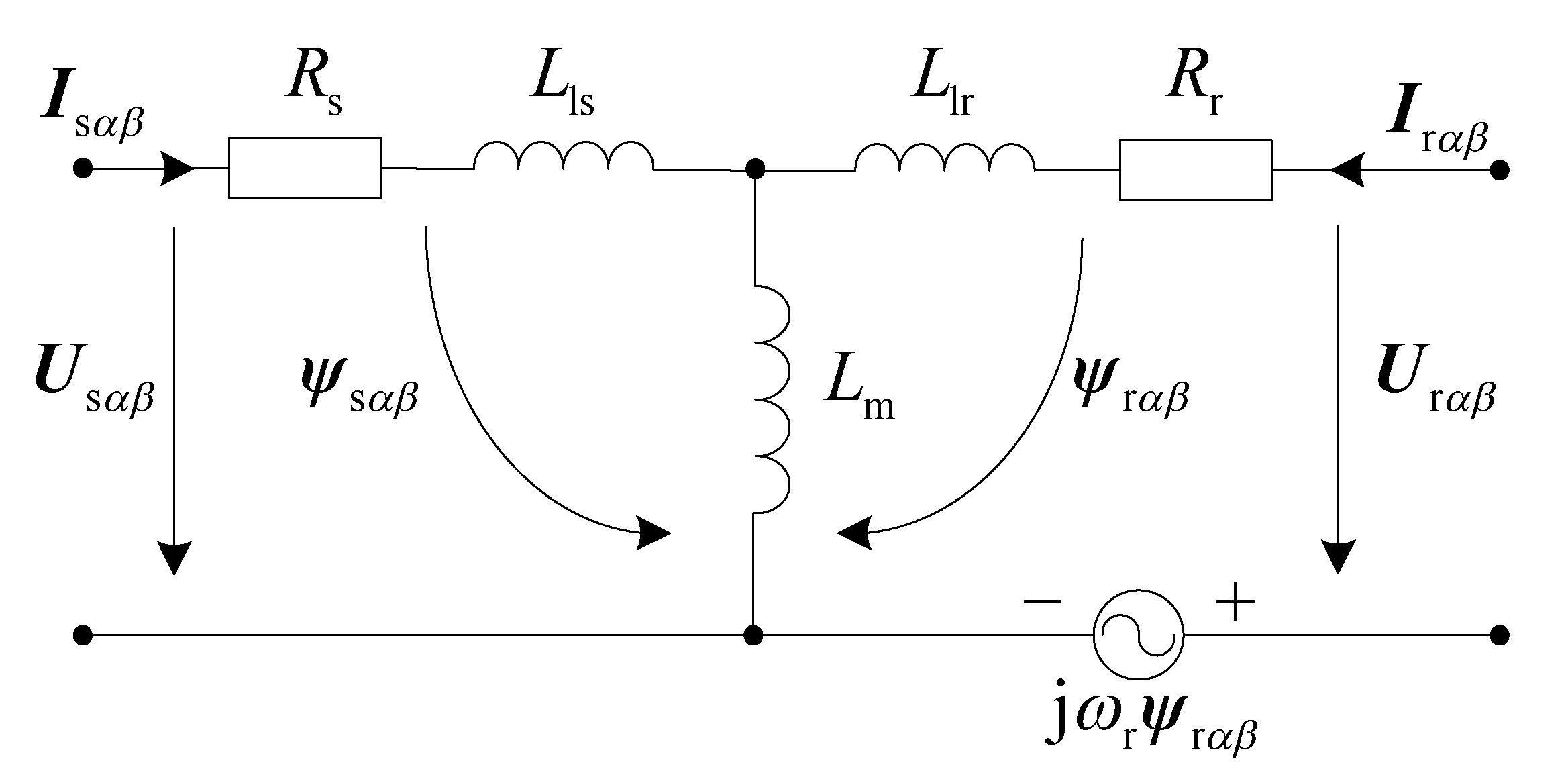
2.2. DFIG Model
3. Control System
3.1. Control Targets
- Target I: To remove the oscillating active power.
- Target II: To remove the oscillating reactive power and also the oscillating torque.
- Target III: To operate with balanced stator currents.
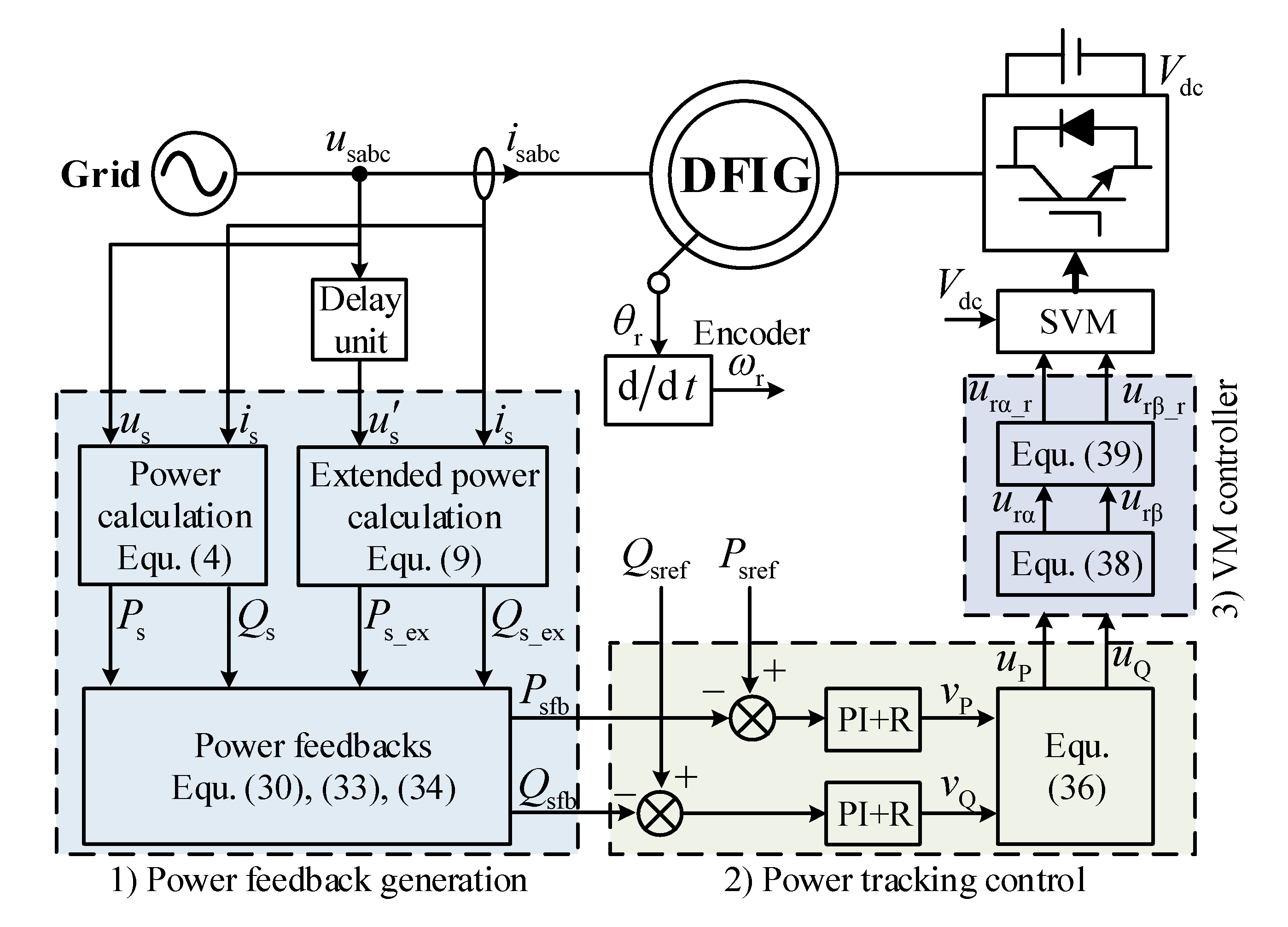
3.2. System Implementation
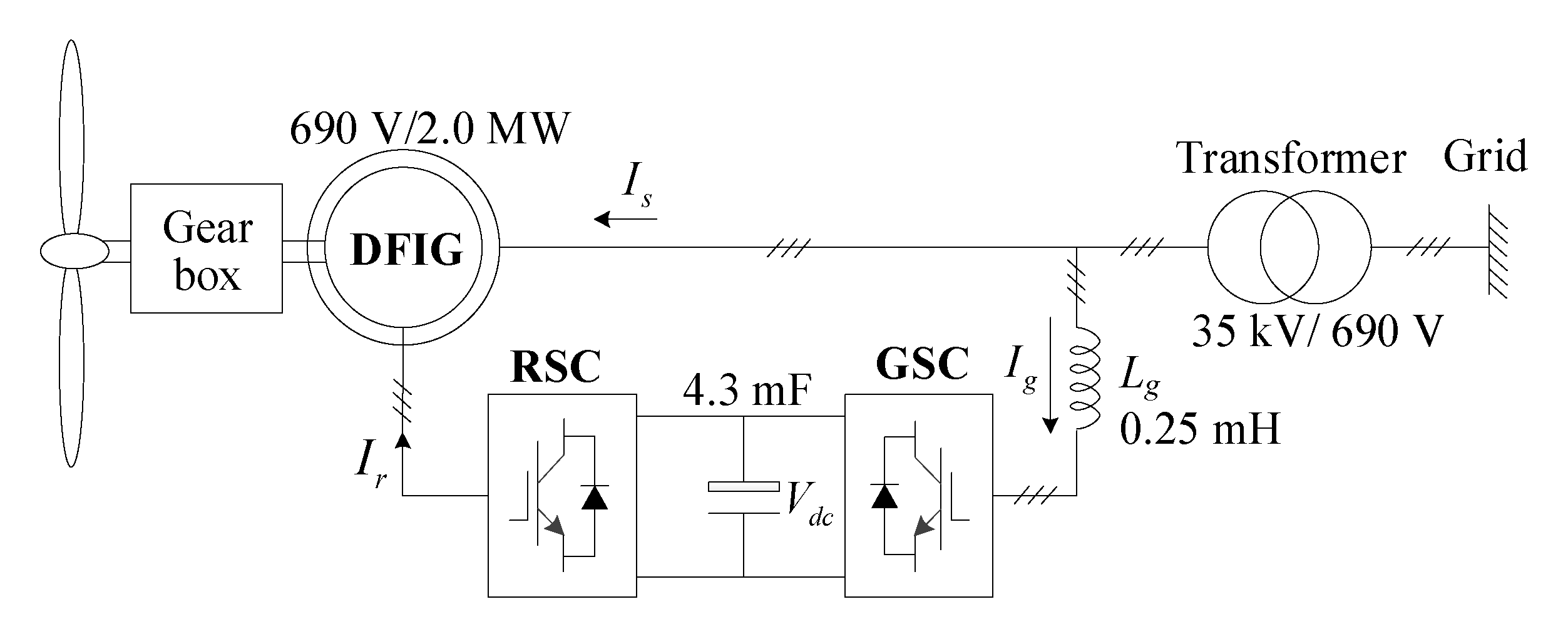
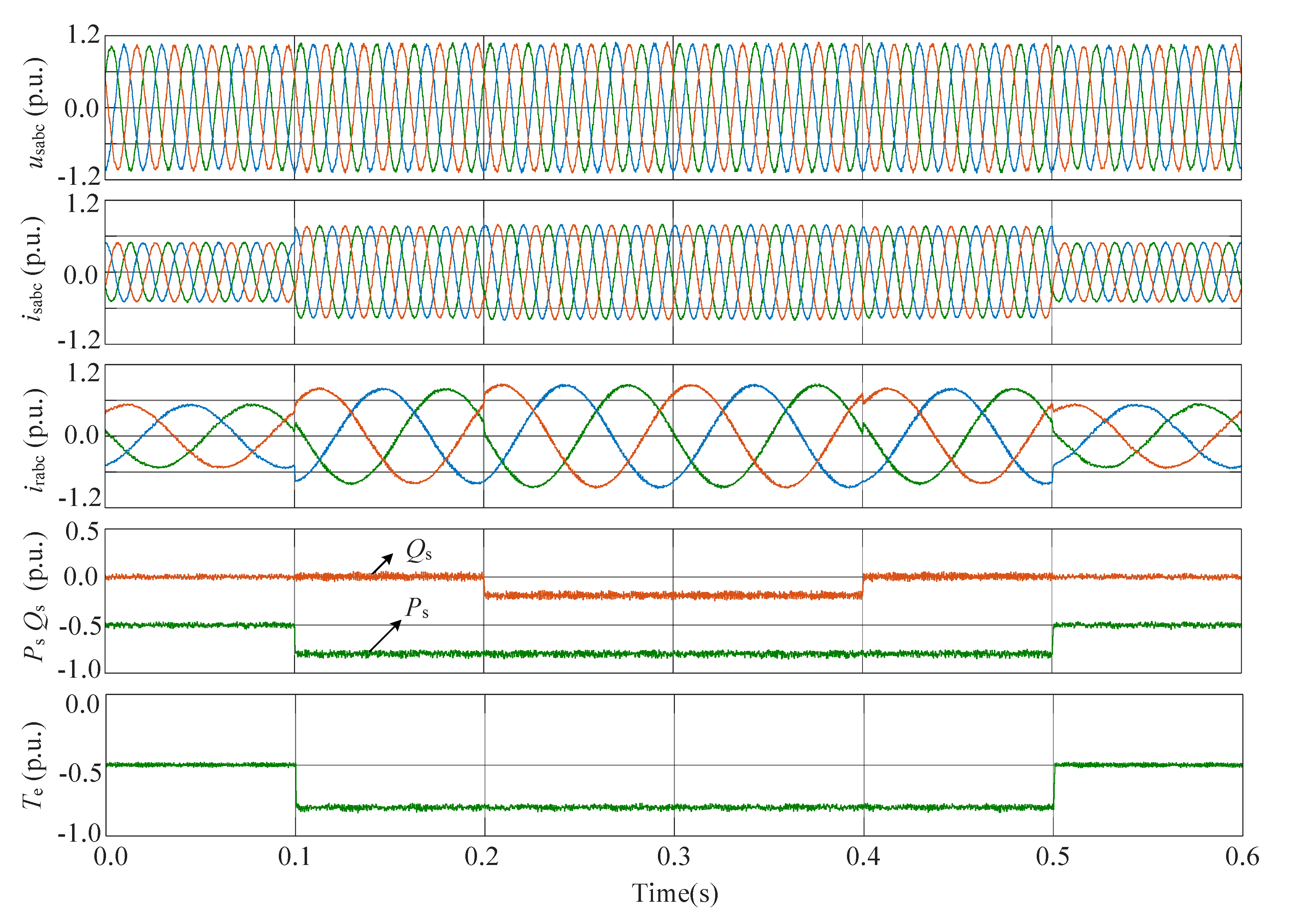
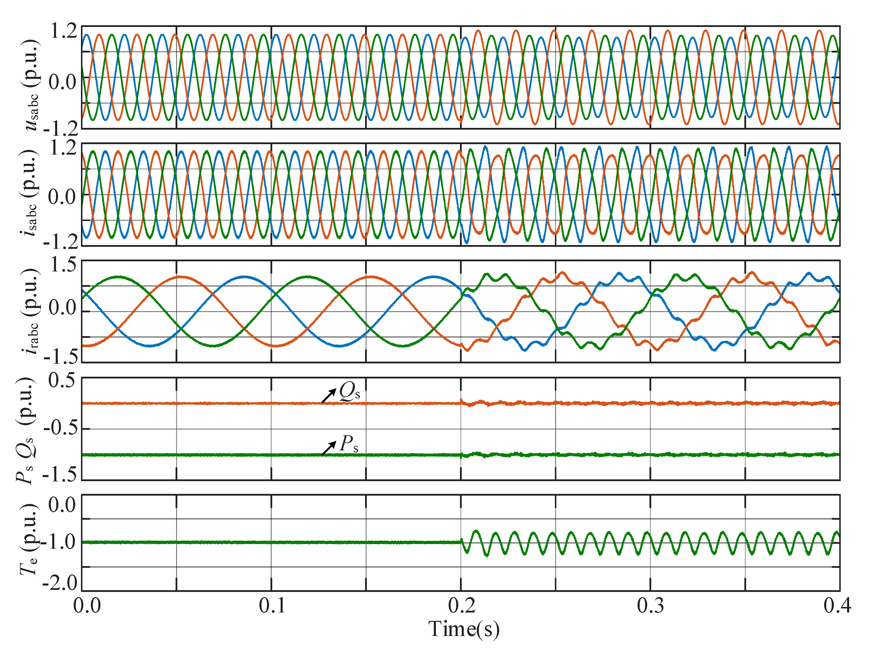
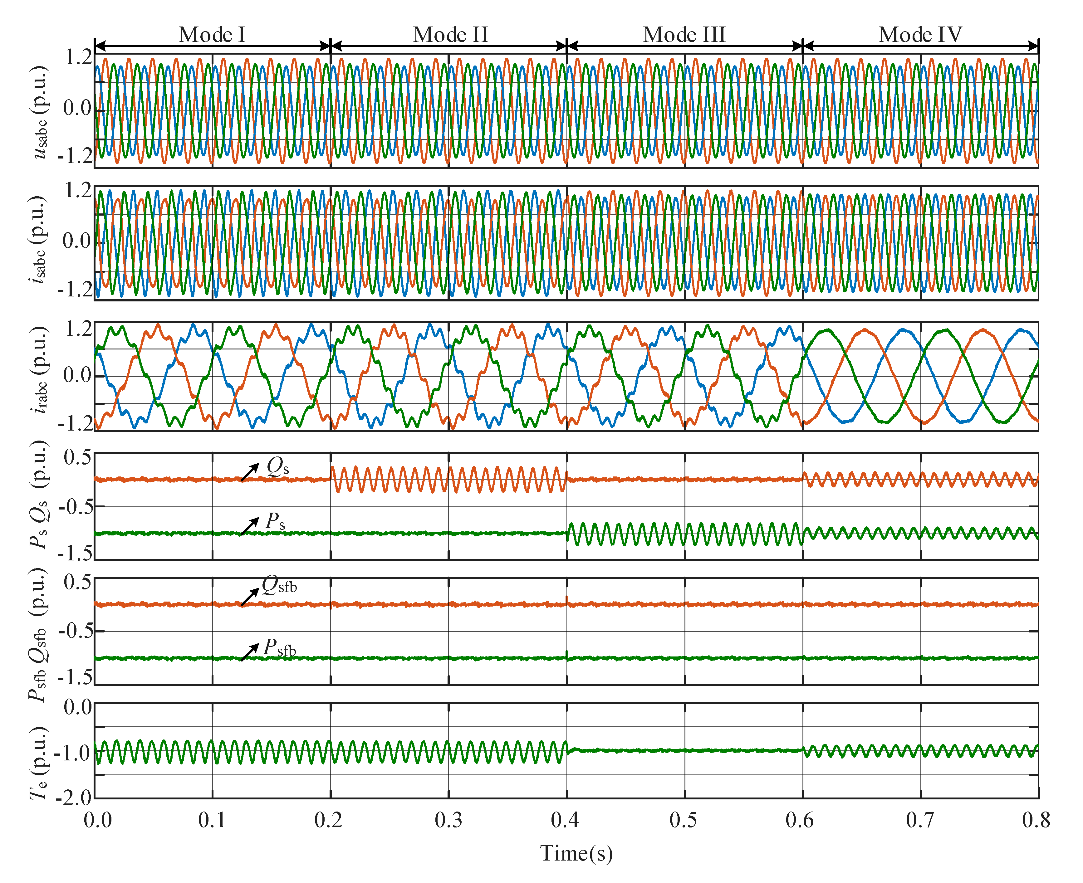
4. Simulation Studies
- (1)
- Mode I: the classical active and reactive powers in Equation (4) are set as the feedback powers.
- (2)
- Mode II: the classical active power and the extended reactive power in Equation (30) are set as the feedback powers.
- (3)
- Mode III: the extended active power and the classical reactive power in Equation (33) are set as the feedback powers.
- (4)
- Mode IV: the calculated active and reactive powers based on the classical and extended powers in Equation (34) are set as the feedback powers.
5. Conclusions
Author Contributions
Funding
Conflicts of Interest
References
- Blaabjerg, F.; Ma, K. Wind energy systems. Proc. IEEE 2017, 105, 2116–2131. [Google Scholar]
- Yaramasu, V.; Wu, B.; Sen, P.; Kouro, S.; Narimani, M. High-power wind energy conversion systems: State-of-the-art and emerging technologies. Proc. IEEE 2015, 103, 740–788. [Google Scholar] [CrossRef]
- Jia, J.; Yang, G.; Nielsen, A.H. A review on grid-connected converter control for short-circuit power provision under grid unbalanced faults. IEEE Trans. Power Deliv. 2018, 33, 649–661. [Google Scholar] [CrossRef] [Green Version]
- Wang, T.; Kong, L.; Nian, H.; Zhu, Z.Q. Coordinated elimination strategy of low order output current distortion for LC-filtered DFIG system based on hybrid virtual impedance method. IEEE Trans. Power Electron. 2019, 34, 7502–7520. [Google Scholar] [CrossRef]
- Shuai, Z.; Xiao, M.; Ge, J.; Shen, Z.J. Overcurrent and its restraining method of PQ-controlled three-phase four-wire converter under asymmetrical grid fault. IEEE J. Emerg. Sel. Top. Power Electron. 2019, 7, 2057–2069. [Google Scholar] [CrossRef]
- Mahamedi, B.; Eskandari, M.; Fletcher, J.E.; Zhu, J. Sequence-based control strategy with current limiting for the fault ride-through of inverter-interfaced distributed generators. IEEE Trans. Sustain. Energy 2020, 11, 165–174. [Google Scholar] [CrossRef]
- Golestan, S.; Guerrero, J.M.; Vasquez, J.C. Three-phase PLLs: A review of recent advances. IEEE Trans. Power Electron. 2017, 32, 1897–1907. [Google Scholar] [CrossRef] [Green Version]
- Zhu, D.; Zhou, S.; Zou, X.; Kang, Y. Improved design of PLL controller for LCL-type grid-connected converter in weak grid. IEEE Trans. Power Electron. 2020, 35, 4715–4727. [Google Scholar] [CrossRef]
- Liu, J.; Yao, W.; Wen, J.; Fang, J.; Jiang, L.; He, H.; Cheng, S. Impact of power grid strength and PLL parameters on stability of grid-connected DFIG wind farm. IEEE Trans. Sustain. Energy 2020, 11, 545–557. [Google Scholar] [CrossRef]
- Shabestary, M.M.; Mohamed, Y.R.I. Asymmetrical ride-through and grid support in converter-interfaced DG units under unbalanced conditions. IEEE Trans. Ind. Electron. 2019, 66, 1130–1141. [Google Scholar] [CrossRef]
- Afshari, E.; Moradi, G.R.; Rahimi, R.; Farhangi, B.; Yang, Y.; Blaabjerg, F.; Farhangi, S. Control strategy for three-phase grid-connected PV inverters enabling current limitation under unbalanced faults. IEEE Trans. Ind. Electron. 2017, 64, 8908–8918. [Google Scholar] [CrossRef] [Green Version]
- Taul, M.G.; Wang, X.; Davari, P.; Blaabjerg, F. Current reference generation based on next generation grid code requirements of grid-tied converters during asymmetrical faults. IEEE J. Emerg. Sel. Top. Power Electron. 2019. [Google Scholar] [CrossRef] [Green Version]
- Guo, X.Q.; Liu, W.; Zhang, X.; Sun, X.; Lu, Z.; Guerrero, J.M. Flexible control strategy for grid-connected inverter under unbalanced grid faults without PLL. IEEE Trans. Power Electron. 2015, 30, 1773–1778. [Google Scholar] [CrossRef] [Green Version]
- Zhang, Y.; Jiao, J.; Xu, D.; Jiang, D.; Wang, Z.; Tong, C. Model predictive direct power control of doubly fed induction generators under balanced and unbalanced network conditions. IEEE Trans. Ind. Appl. 2020, 56, 771–786. [Google Scholar] [CrossRef]
- Zhou, D.; Tu, P.; Tang, Y. Multi-vector model predictive power control of three-phase rectifiers with reduced power ripples under non-ideal grid conditions. IEEE Trans. Ind. Electron. 2018, 65, 6850–6859. [Google Scholar] [CrossRef]
- Wang, X.; Sun, D. Three-vector-based low-complexity model predictive direct power control strategy for doubly fed induction generators. IEEE Trans. Power Electron. 2017, 32, 773–782. [Google Scholar] [CrossRef]
- Zhang, Y.; Jiao, J.; Xu, D. Direct power control of doubly fed induction generator using extended power theory under unbalanced network. IEEE Trans. Power Electron. 2019, 34, 12024–12037. [Google Scholar] [CrossRef]
- Li, L.; Nian, H.; Ding, L.; Zhou, B. Direct power control of DFIG system without phase-locked loop under unbalanced and harmonically distorted voltage. IEEE Trans. Energy Convers. 2018, 33, 395–405. [Google Scholar] [CrossRef]
- Kabiri, R.; Holmes, D.G.; Mcgrath, B.P. Control of active and reactive power ripple to mitigate unbalanced grid voltages. IEEE Trans. Ind. Appl. 2016, 52, 1660–1668. [Google Scholar] [CrossRef]
- Nian, H.; Shen, Y.; Yang, H.; Quan, Y. Flexible grid connection technique of voltage-source inverter under unbalanced grid conditions based on direct power control. IEEE Trans. Ind. Appl. 2015, 51, 4041–4050. [Google Scholar] [CrossRef]
- Sun, D.; Wang, X.; Nian, H.; Zhu, Z.Q. A sliding-mode direct power control strategy for DFIG under both balanced and unbalanced grid conditions using extended active power. IEEE Trans. Power Electron. 2017, 33, 1313–1322. [Google Scholar] [CrossRef]
- Gui, Y.; Li, M.; Lu, J.; Golestan, S.; Guerrero, J.M.; Vasquez, J.C. A voltage modulated DPC approach for three-phase PWM rectifier. IEEE Trans. Ind. Electron. 2018, 65, 7612–7619. [Google Scholar] [CrossRef] [Green Version]
- Gui, Y.; Kim, C.; Chung, C.; Guerrero, J.M.; Guan, Y.J.; Vasquez, J.C. Improved direct power control for grid-connected voltage source converters. IEEE Trans. Ind. Electron. 2018, 65, 8041–8051. [Google Scholar] [CrossRef] [Green Version]
- Power Quality-Frequency Deviation for Power System; Chinese National Standard GB/T 15945-2008; Standardization Administration of the PRC: Beijing, China, 2008.
- Compatibility Levels for Low-Frequency Conducted Disturbances and Signaling in Public Low-Voltage Power Supply System; IEC 61000-2-2-2002; International Electrotechnical Commission: Geneva, Switzerland, 2002.


| Parameter | Value | Parameter | Value |
|---|---|---|---|
| Rated power | 2.0 MW | Rated voltage | 690 V |
| Rs | 0.0083 p.u. | DC voltage | 1100 V |
| Rr | 0.0069 p.u. | Lδs | 0.090 p.u. |
| Lm | 4.810 p.u. | Lδr | 0.065 p.u. |
| Stator/rotor turns ratio | 0.33 | Pole number | 4 |
| kp | 20 | ki | 40 |
| kr | 500 | ωc | 10 |
| Mode I | Mode II | Mode III | Mode IV | |
|---|---|---|---|---|
| isabc total harmonic distortion (%) | 10.2 | 1.8 | 1.8 | 1.7% |
| isabc current unbalance factor (%) | 1.1 | 10.8 | 9.1 | 0.1 |
| Ps oscillation (%) | 0.4 | 0.4 | 19.2 | 9.3 |
| Qs oscillation (%) | 0.4 | 19.8 | 0.4 | 9.6 |
| Te oscillation (%) | 19.5 | 19.4 | 0.4 | 11.4 |
Publisher’s Note: MDPI stays neutral with regard to jurisdictional claims in published maps and institutional affiliations. |
© 2020 by the authors. Licensee MDPI, Basel, Switzerland. This article is an open access article distributed under the terms and conditions of the Creative Commons Attribution (CC BY) license (http://creativecommons.org/licenses/by/4.0/).
Share and Cite
Cheng, P.; Wu, C.; Ning, F.; He, J. Voltage Modulated DPC Strategy of DFIG Using Extended Power Theory under Unbalanced Grid Voltage Conditions. Energies 2020, 13, 6077. https://doi.org/10.3390/en13226077
Cheng P, Wu C, Ning F, He J. Voltage Modulated DPC Strategy of DFIG Using Extended Power Theory under Unbalanced Grid Voltage Conditions. Energies. 2020; 13(22):6077. https://doi.org/10.3390/en13226077
Chicago/Turabian StyleCheng, Peng, Chao Wu, Fuwei Ning, and Jing He. 2020. "Voltage Modulated DPC Strategy of DFIG Using Extended Power Theory under Unbalanced Grid Voltage Conditions" Energies 13, no. 22: 6077. https://doi.org/10.3390/en13226077