1. Introduction
The use of solar energy to generate electricity has increased sharply worldwide, with photovoltaics being the most commonly used conversion technology [
1,
2]. However, there has also been an increase in the use of solar thermal power plants [
1,
2]. Parabolic trough power plant technology still accounts for the largest share of this, but some solar power towers have also been built [
3]. Water/steam or salt is used as the heat transfer fluid (HTF) for the solar power tower plants [
https://solarpaces.nrel.gov]. Solar power towers using air as an HTF have not yet become established despite promising cost and risk reduction potentials. The associated storage technology, regenerators, has therefore not been further developed for use in this concentrated solar power (CSP) technology and still corresponds to the state of the art developed in the HOTSPOT project [
4,
5]. There, setups with ceramic honeycombs and ceramic ball fillings proved to be the most suitable inventory. In order to make the technology as inexpensive and innovative as possible from the storage side, packed beds of natural stones were also successfully investigated at that time. Due to their natural origin, however, natural stones often have fluctuations in their properties and, due to their fracture characteristics, irregular and pointed surfaces, which can pose a risk of damage to the inner insulation and thus require countermeasures to be taken, which can be constructively demanding or cost-intensive.
In the literature, other equally cost-effective alternatives from waste materials have already been investigated, including slag [
6,
7,
8,
9,
10]. The focus there was on the thermal and mechanical characterization of specific types of slag and other wastes. The study of one or more applications using such material as an inventory has not yet been the subject of published research. This is the case for the first time with the EU project REslag [
11].
The focus of the project, which was completed in 2019 and involved 18 partners from eight countries, was on the investigation of electric arc furnace (EAF) slag and its usability for five very different applications. The main objective was to create pilot plants for these applications using this specific type of slag. The background to this is the fact that over 20 million tons of this type of slag are produced in the European Union every year, but around a quarter of this is not used but landfilled [
11]. One of the applications investigated in the project is CSP with open volumetric receiver, where the slag is to be used as inventory material for the thermal energy storage (TES), see
Figure 1.
This paper outlines the main work undertaken in the project on this CSP technology. The focus is on the project results that have not yet been published. For the results already published in the respective context, reference is made to the literature sources. The work was divided into four phases. Firstly, the target values for the storage facilities on full-scale and pilot-scale were determined in the specification phase. Then, in the concept phase, suitable storage concepts were developed, preliminarily designed, systematically evaluated and finally, on this basis, a lead concept was defined for further investigations. In the detailed phase, this lead concept was examined in detail with regard to thermal performance, fluid mechanics and thermomechanics. In the final phase, suitable experiments were carried out; on the one hand, material investigations to qualify the type of slag used and, on the other hand, pilot-scale tests to qualify the structure and to validate the thermal design models.
2. Specification Phase: Specification and Requirements for Slag’s Use in Solar Power Tower Plants Using Air as Heat Transfer Fluid
The development of regenerators for use in solar power tower plants using air as HTF is primarily focused on the target size, i.e., the size of a power plant that would most likely be built for commercial purposes. The size of the pilot plant to be built in the project can be derived from this in a meaningful way.
For this purpose, it is first necessary to find out what a reasonable target size is and to preliminarily design the related TES. In order to provide important boundary conditions for the production of the slag pebbles to be used as inventory, it was useful in this phase of the project to carry out a sensitivity study with regard to the thermal properties. The specification phase ends with the definition of the objectives of the construction of a pilot storage facility and the design of the same.
The Jülich Solar Power Tower in Germany, see
Figure 2, is the only plant in the world with an open volumetric receiver and TES. This experimental plant was inaugurated in 2009 to further develop this technology [
13,
14].
The system uses an open volumetric receiver technology developed at German Aerospace Center (DLR). In the primary circuit, air at atmospheric pressure is heated to temperatures of about 700 °C. This solar heat is used to generate steam at 100 bar and 500 °C in a steam generator, which then drives a steam turbine with a power of 1.5 MW
el. Parallel to the steam generator and receiver, a TES is integrated into the air circuit, see
Figure 1. It is designed as a direct-flow regenerator storage, an installation which is still unique in this application.
As the Jülich solar power tower is the only installation of this type, but it is only a demonstration plant, no targets for large-scale plants can be read out. A literature research was therefore carried out. However, as no consistent data set of a specific plant was published, the collected data could only serve as a guideline. Accordingly, the target values were determined on the basis of the literature research and internally available knowledge, see
Table 1.
The TES for the full-scale CSP plant defined in this way was preliminarily designed with the aid of a simplified thermal model for the aforementioned Huelva site, considering the radiation conditions there and the course of the sun. Details are available in [
12]. With regard to the particle size of the slag pebbles to be selected, an equivalent diameter of 0.03 m has proved to be a reasonable size.
The essential material values required for the thermal design are summarized in
Table 2. In order to provide an indication for the manufacturing process of the sintered slag pebbles, a sensitivity analysis was performed with regard to these characteristics by varying the respective value given in
Table 2 by ±20%. This is to simulate a possible uncertainty in the fulfillment of these values during production. As a result of the preliminary design, a solution band is obtained in
Figure 3 with additional variation of the height and diameter of the storage, which reflects the uncertainty if the thermal material values vary to the extent mentioned.
An increase in the values leads to smaller geometric dimensions for the TES and its pressure losses. This is mainly due to the smaller volumes at higher density and higher specific heat capacity. The diameter for a container is here representative for the cross-sectional area. For small storage heights, the storage tank would be designed modularly for structural reasons, but also for reasons of more homogeneous flow distribution.
The overall objective of the REslag project, with regard to this technology investigated here, was to test the regenerator TES system for future high-temperature CSP plants using air as HTF and to demonstrate that the concept of using steel slags as packed bed storage material in a large-scale power plant leads to a technically feasible and economically viable solution. The main technical objectives of the pilot storage facility “HOTREG” were to evaluate the arrangement during operation and to validate the thermal models. It is therefore necessary to obtain thermally equivalent results with the pilot plant, and so the values obtained from reduced regenerator length Λ and reduced period duration Π [
12] must be reproduced. Since HOTREG already exists, see [
16], the geometric dimensions of the heat storage tank are defined. The parameters that can be changed are therefore the equivalent particle diameter of the slag pebbles, the air mass flow rate and the cycle duration.
The Λ and Π values that can be realized with HOTREG are shown in
Figure 4.
Table 3 shows the required slag diameters, the air mass flow and the cycle duration for the trails.
The next step is to select a suitable parameter set. For this purpose, the mass flow range of the test equipment must be considered, which ranges from 220 to 720 kg/h. In order to be able to test both the normal load behavior and the behavior under overload and underload conditions, a mass flow rate should be selected which is in the middle of the possible range. This is very well the case for number 5, where the particle diameter is 0.03 m, as for the target size. Therefore, this configuration was chosen.
With the completion of the specification phase, the target values for the power plant are defined in the target scale and the related storage facility. Furthermore, the test parameters for pilot plant operation were defined.
3. Conception Phase: Design Studies and Systematic Comparative Assessment
On the basis of the defined target values for the full-scale facility, concepts for the design of the storage facility were developed, thermally preliminarily designed and systematically evaluated. On the basis of the evaluation, a lead concept was selected for further processing in the project. This phase was set out in detail in another publication [
12], so only a brief summary is given here. Furthermore, results not yet published will be described.
Figure 5 shows the concepts developed for the TES in the form of a matrix. The main differentiating characteristics here are the arrangement and direction of flow.
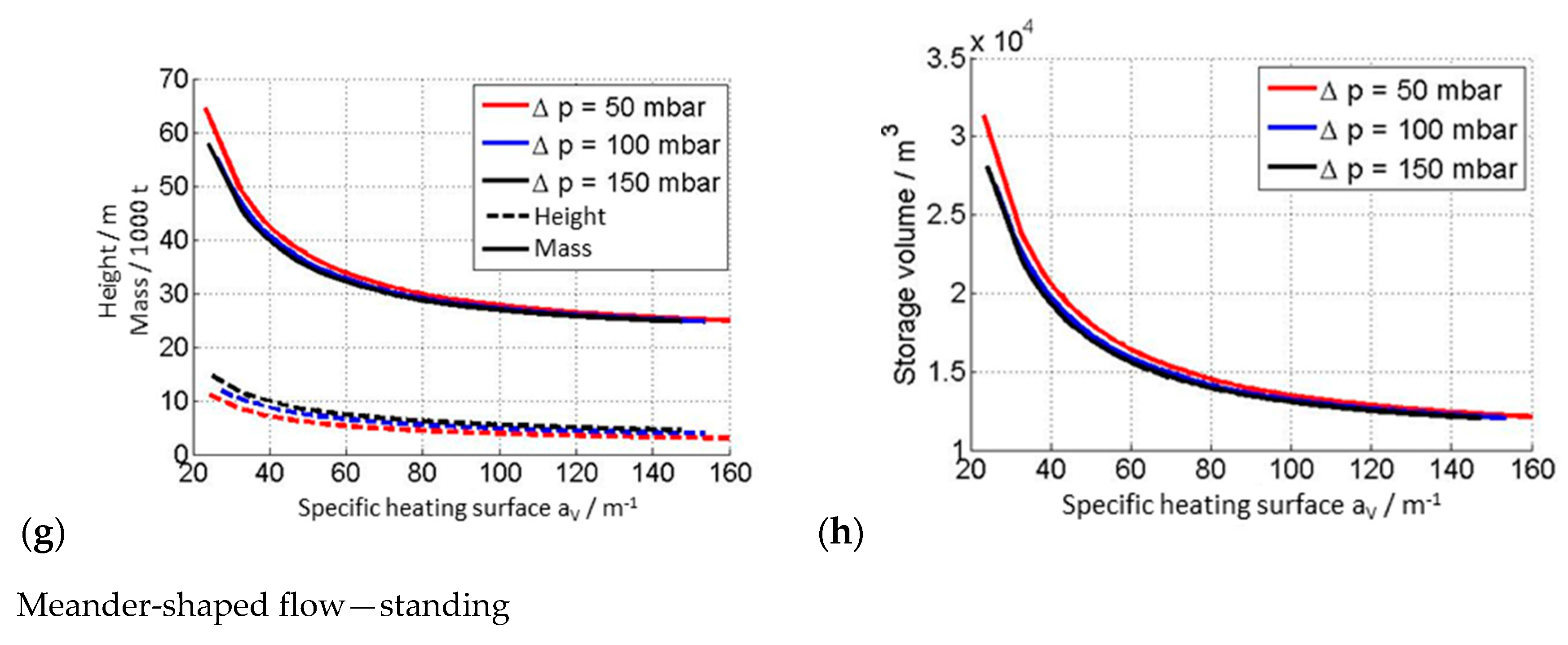
For these six concepts, thermal preliminary designs were carried out. Here, the particle size of the slag pebble was again varied as a parameter in the form of the specific heating surface. Some essential design results for the four most promising concepts are shown in
Figure 6, namely the required inventory mass, the storage volume and the dimension of the storage bed in flow direction, each for different maximum pressure losses along the storage bed and for different specific heating surfaces.
In all concepts it can be seen that an increase in the specific heating surface of the inventory leads to a decrease in inventory mass and storage length as well as storage volume. This is due to an increase in storage utilization. In all concepts, the permissible pressure drop has only a minor influence on the required inventory mass and the storage volume, but has a strong effect on the height and diameter of the storage tank. While the storage height decreases with decreasing pressure drop, the diameter increases and vice versa. A slightly greater influence on the storage volume due to the permissible pressure drop can be seen in the radial flow concept, since here the volume increases over-proportionately with increasing flow length.
With the option “Axial flow—standing” (a, b), a storage mass of approximately 27,000 tons is required for the particle diameter of 0.03 m—which corresponds to a specific heating surface of 120 m2/m3. The storage bed height is between 10 m at 50 mbar and 16 m at 150 mbar. The results of the option “Axial flow—lying” (c, d) are comparable. Here the difference is the flow area, which is not circular but rectangular. The length is comparable to the height of the standing option and the hydraulic diameter of the flow cross-section is comparable to the diameter of the storage. In direct comparison between the standing and lying option, the latter has a reduced hydraulic diameter due to the rectangular flow cross-section. Its area is about 1.27 times larger than a circular area of the same hydraulic diameter. Thus, the height to diameter ratio is also higher.
The concept “Radial flow—standing” (e, f) is characterized by an initiation of the hot fluid in the diametrical center of the storage inventory and an outlet at the storage shell. Compared to the axial flow variant, an increase in the specific surface area of the inventory leads to a decrease in the TES diameter, inventory mass and volume and an increase in height. This results in an increase in the storage utilization.
The meander-shaped flow option (g, h) shows comparable curves to the other axial options. The major difference, however, is the resulting storage geometry. The heights are three times smaller and the diameters are two times larger. This is due to the inner meandering shape of the storage. As shown in
Figure 5, the storage shows two changes in the direction of fluid flow.
In order to identify a lead concept, an evaluation method was finally developed and applied, which is essentially based on two established management tools from product development, namely quality function deployment (QFD) and failure mode and effect analysis (FMEA). This analysis approach makes it possible to weigh up many evaluation criteria in terms of their significance and to quantify their fulfilment for different concepts. The evaluation carried out within the framework of REslag and described in detail in [
12] distinguishes between economic and technical requirements. The following essential criteria were considered:
Economic requirements: Long lifetime, high operational availability, low investment costs, low operating costs, low space need and high storage degree of utilization.
Technical requirements: High degree of maturity, high storage degree of uniformity, good scalability, low complexity, low expense of system integration and low maintenance effort.
Each concept was then evaluated for its fulfilment with these criteria, and the results of the preliminary designs presented here were also included. The highest overall aptitude value is achieved with the vertical TES with axial flow direction (83%), followed by the horizontal TES with axial flow direction (75%) and the vertical TES with radial flow direction (72%). This is mainly due to high aptitude values in the areas with high weighting factors. The main factors here are operational availability, lifetime, investment costs and degree of maturity. While horizontal installations promise a longer lifetime due to less material failure in the storage bed, the more or less mature vertical axial design achieves better values in the criteria of degree of maturity, operational availability and investment costs. Radial-flow variants have clear advantages in terms of operating costs due to the low-pressure losses along the flow path and the storage degree of uniformity. In the overall assessment, however, the vertical-axial concept is slightly ahead of the horizontal-axial and vertical-radial concepts.
At the end of the conceptual design phase, suitable concepts for the storage design for a full-scale power plant are available, have been pre-designed and systematically evaluated in a comparative manner. A lead concept for further consideration in the project was defined: “Axial flow—standing”.
4. Detailing Phase: Thermal, Fluid Mechanical and Thermomechanical Operating Characteristic Behavior of the TES
The lead concept “Axial flow—standing” was further examined in detail during this phase. For this purpose, thermal calculations on the thermal behavior of the storage at different load points, flow-mechanical calculations on flow distribution and thermomechanical calculations on force and stress distribution were carried out.
4.1. Thermal Operating Characteristic Behavior
The thermal performance of the TES lead concept was extensively investigated in the project and published in [
17,
18]. There the focus was on the normal daily cycle under design conditions, see
Table 1.
In this section, the focus is on the descriptions with regard to the thermal storage behavior at partial load and solar irradiation conditions, which differ greatly from those of the design day.
Figure 7 shows the partial load behavior for the TES lead concept. Here, the temperature profiles versus the storage height at the end of the charging and discharging process for three different partial loads, namely 25% (a), 50% (b) and 75% (c) of the charging and discharging mass flow in the design case, are considered and compared to the design case (d), respectively full load case. The storage degree of utilization increases with a higher percentage of the load. In the diagram for 25% partial load (a), over two-thirds of the storage height, there is not even a temperature swing of 100 K between charging and discharging. Furthermore, at the storage height of 9 m a temperature jump can be seen. This is caused by the low mass flow and the large storage mass. During the charging period only a small part of the storage mass can be charged at full temperature; the energy is too low for the rest. This effect is reduced at higher loads.
To determine the behavior of the TES under winter and summer conditions, a representative day is chosen for both seasons, see
Table 4.
Figure 8 shows the thermal charging and discharging behavior of the storage. In addition to the temperature curves in the inventory at the end of charging and discharging versus the storage level (a, c), the temperature curves versus the time for the fluid at the outlet of the storage during charging and discharging (b, d) are also shown here. For comparison purposes, the design curves are shown as dashed lines.
Under the present irradiation conditions in winter (a, b), the TES cannot be fully charged. This can be seen from the inventory temperature curves (a). The charging curve (red) only shows a TES that is about 80% charged compared to the design point. This leads to a correspondingly lower storage degree of utilization, which is expressed as the area between the two temperature curves for charging and discharging in the storage inventory (a). After about 5.2 h, the fluid outlet temperature during discharge (b) falls below the minimum temperature of 640 °C, which results from the previously defined maximum temperature drop of 60 K at the end of discharge period. Therefore, the TES will not be further discharged beyond this period. The outlet temperature during charging also increases earlier than on the design day, but does not reach such a high level at the end of the charging process. This results from the higher temperature level in the storage at the end of the discharging period.
During the summer day (c, d) it is shown that the storage tank is thermally “overloaded”. Compared to the design day, it therefore stores more thermal energy and also has a higher storage efficiency. This leads to a smaller drop of the discharge output temperature (d). Due to these two facts, a longer discharge and thus a higher energy supply over the discharge period at design is possible. The outlet temperature during charging only rises later, but with a higher gradient, and reaches a significantly higher level of about 520 °C at the end of the charging process than on the design day, where it is only 400 °C. This results from the higher storage degree of utilization.
4.2. Fluid Mechanical Aspects
When storing thermal energy in direct-flow regenerators, an even flow distribution for the heat transfer fluid when it meets the inventory should be aimed for to ensure that the inventory is charged and discharged evenly, thus avoiding performance losses. For the lead concept, the influence of the distribution space on the uniformity of the flow was investigated by fluid mechanics calculation using the software package ANSYS CFX. Distribution spaces with axial inflow were considered in stationary and isothermal calculations. The most promising options were additionally considered in more detail in cyclical calculations, in which the influence of the distribution space on the storage capacity is quantified.
A computational fluid dynamics (CFD) model was created to simulate the flow conditions in the inflow/outflow and in the inventory. The CFD code solves the coupled differential equations for the conservation of mass, momentum and energy. For the turbulence the shear stress transport (SST) model is used.
The modelling of all discrete particles in the computational grid would be theoretically possible, but would require considerable computing effort due to the large number of particles. For this reason, porous models are used here, which disregard a discrete resolution of the porous structures. Instead, it is assumed that each computing cell has both a gaseous and a solid part. A heterogeneous model is used to calculate the energy conversion. The porous model only determines the average temperature in each computing cell. The use of this temperature overestimates the calculated heat transfer, because a too high temperature difference is assumed. This can be corrected by the factor φ proposed by Hausen [
19], see Equation (1).
here D
P is the particle diameter, a
s the thermal diffusivity of the solid and θ the period duration.
In order to assess an even flow distribution, it must be quantified. The uniformity index gamma (γ) is used for this purpose [
20]. The degree of uniform distribution γ
A is evaluated on flat surfaces. Gamma takes values between 1 (complete uniformity) and 0 (the total mass flow passes through one point). The integral uniformity index
γint, as defined in Equation (2), is used to evaluate the uniformity distribution for the entire storage. It is the weighted average of the local uniformity indices over the storage length
LStorage.
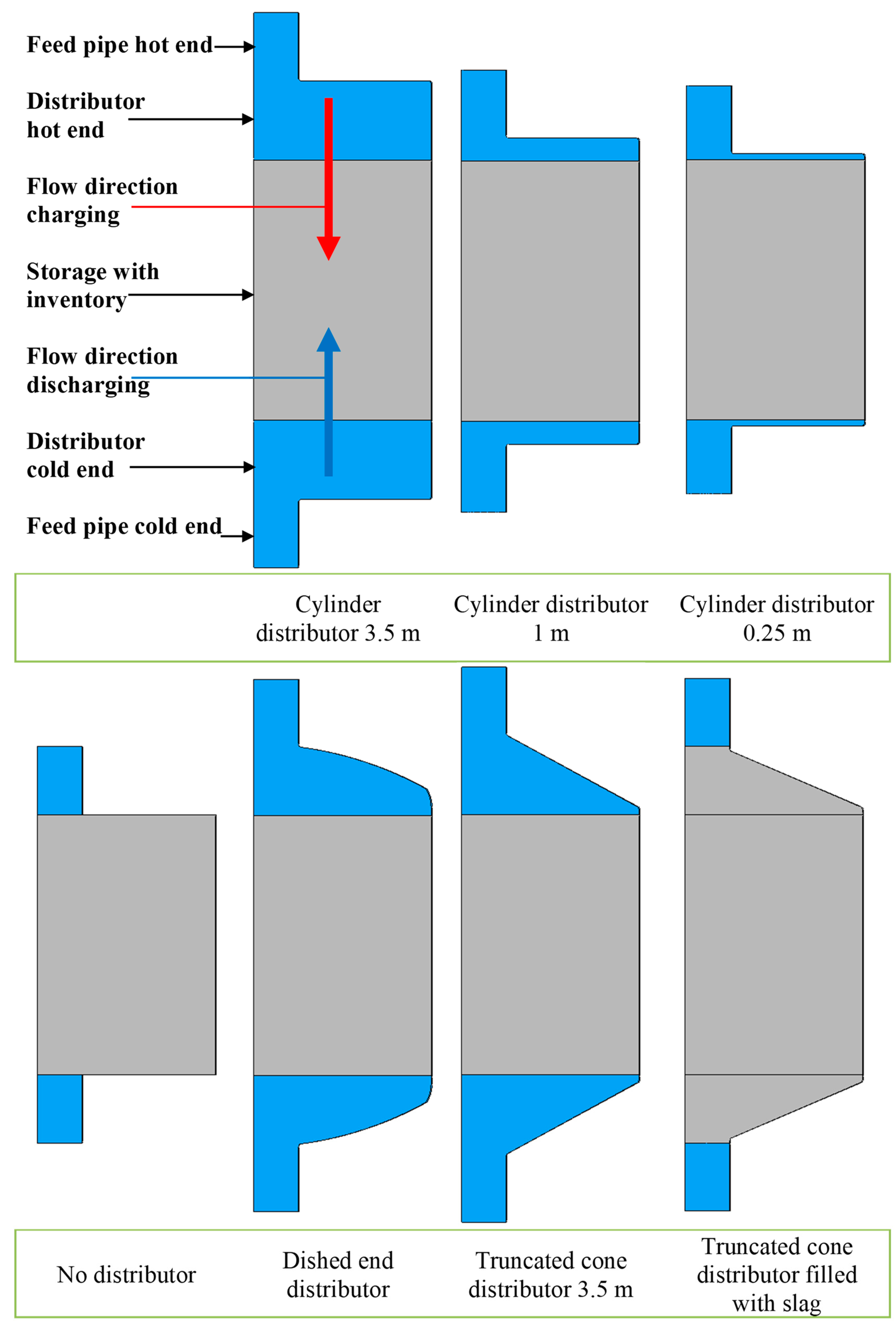
For seven different distributor designs, cf.
Figure 9, isothermal stationary calculations were carried out for the charging and discharging process at full load and at 50 percent partial load:
Cylindrical distributor 3.5 m: This is the basic case.
Cylindrical distributor 1 m: The height has been reduced to save space and costs.
Cylindrical distributor 0.25 m: The height is further reduced to save even more space and costs.
No distributor: Here the distributor is omitted completely to save maximum space and costs. The supply line leads directly to the inventory.
Dished end distributor: The domed end is a common shape for pressure vessels.
Truncated cone distributor 3.5 m: Truncated cones can act as a diffuser, and thus reduce the pressure loss.
Truncated cone distributor filled with slag pebbles: Since the distributor also contains inventory material, the storage tank can be designed accordingly smaller or the storage capacity increased.
The general boundary conditions for the calculations are listed in
Table 5.
A rotational symmetry is given for all these seven constructions, which could be used in the CFD calculations to reduce the computing time.
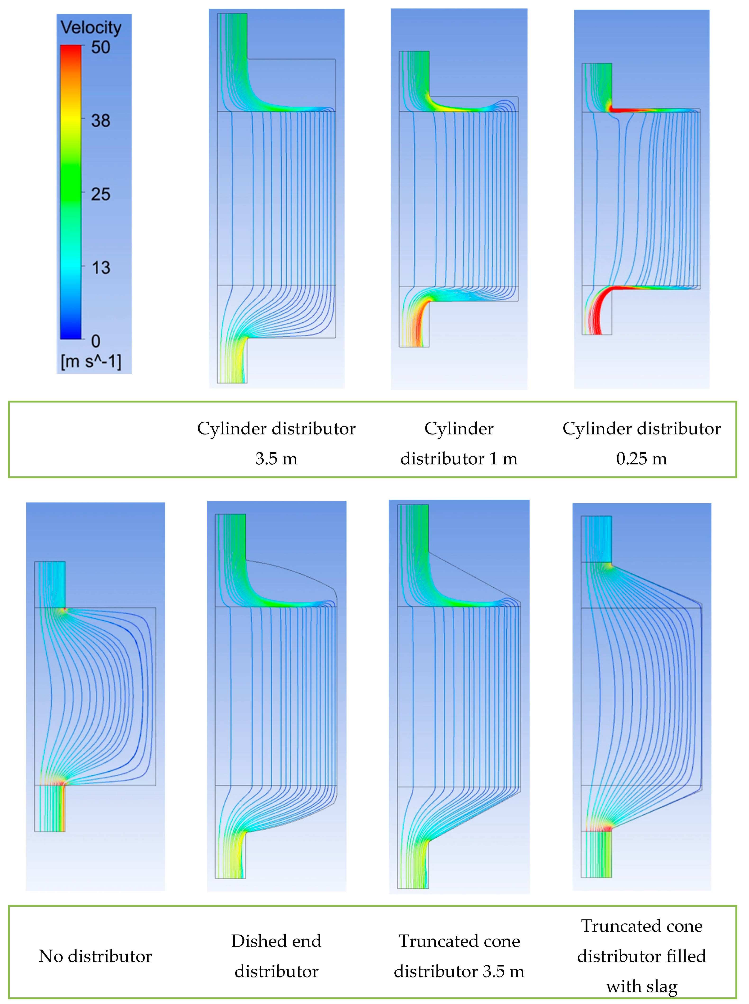
The detailed calculation results are shown to be exemplarily for the case “Charging, full Load”, since the other cases show comparable results. The distributions of the velocity in the main flow direction
v for all seven distributor forms are shown in
Figure 10. Streamline diagrams are shown in
Figure 11.
For the “cylinder distributor 3.5 m” form, the fluid enters the distributor and flows through it. The main part of the distributor space is not used by the fluid. It is distributed over the entire cross-section only shortly before entering the inventory. This behavior can also be observed for the forms “dished end distributor” and “truncated cone distributor 3.5 m”. This indicates the formation of a vortex in this area of the distributor. This vortex is clearly visible in the vector diagrams in
Figure 12. In the outflow area, the entire collector space is used. For the shape “cylinder distributor 1 m” there is less space in the distributor. As a result, a much smaller vortex is formed. The contour and streamline diagrams provide no evidence of an uneven distribution of the flow in the inventory for these four mentioned distributor forms. There is not enough space in the “cylinder distributor 0.25 m” to form a vortex. However, the velocities in the distributor are much higher, resulting in a greater pressure drop. Zones with higher speeds can be seen in the contour diagram. With the option “no distributor” the zones near the supply lines must be flowed through with a higher speed, which leads to a worse distribution. The streamline diagram also shows a worse distribution of the flow and dead zones in the corners of the tank. With the option “truncated cone distributor filled with slag” the streamline diagram gives little evidence of poor distribution.
The integral homogeneity index γ
int for all cases is shown in
Table 6.
It can be seen that full or partial load has only a minor influence on homogeneity. The uniformity of the flow is excellent for the distributors “cylinder distributor 3.5 m”, “cylinder distributor 1 m”, “dished end distributor” and “truncated cone distributor 3.5 m”. The uniformity of the flow is still very good for “cylinder distributor 0.25 m”, but the pressure drop increases by 33% compared to “cylinder distributor 3.5 m”, see
Table 7. The uniformity of flow is still fine for “truncated cone distributor filled with slag”, but the pressure drop is much higher. For “no distributor”, the pressure drop is also very high, and the uniformity is also much worse than for the other designs. With these two designs, the total mass flow must pass through a small cross-section filled with inventory. This causes high velocities in the packed bed, which leads to high pressure losses. Therefore, it is not a reasonable measure to leave out the distributor chamber.
For full-scale application, the “cylinder distributor 1 m” is the most promising option because of its excellent uniformity and good pressure drop. It also requires the least amount of space. The forms “cylinder distributor 3.5 m”, “dished end distributor” and “truncated cone distributor 3.5 m” are also useful options. If there are other reasons for realizing these shapes, there are no objections from a fluid mechanics point of view. These shapes have no disadvantages in this respect, but also no advantages. The distributor should not be too small as with the “cylinder distributor 0.25 m”, because the speeds and the pressure drop increase.
Based on these results, the most promising distributor shape, the shape with the best uniformity and the worst shape for transient cyclic calculations were selected: “cylinder distributor 1 m”, “cylinder distributor 3.5 m” and “no distributor”.
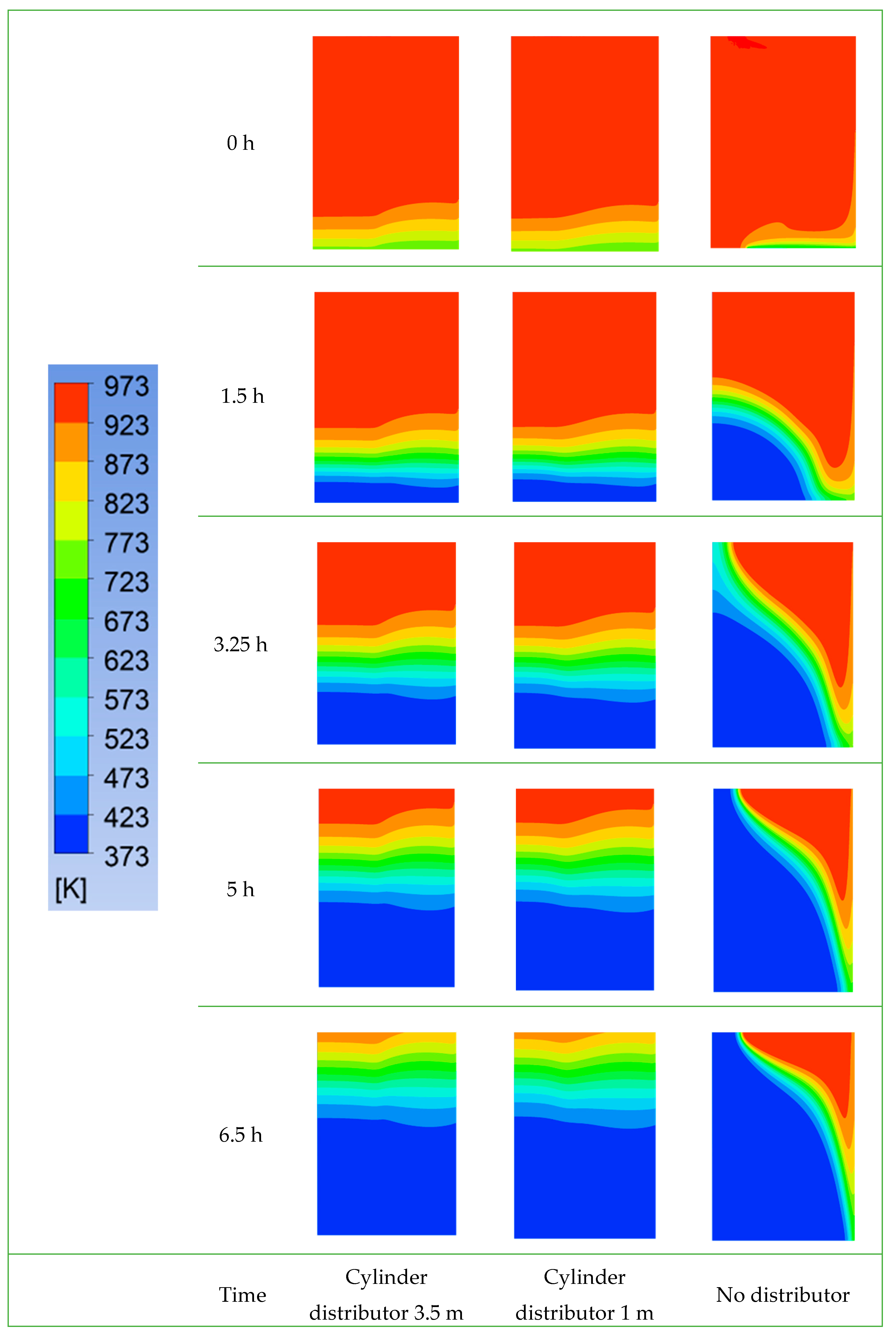
In these transient cyclic calculations 10 cycles (charging and discharging) were calculated to achieve the cyclically steady state. The following results refer to the 10th cycle. The temperature distribution across the storage during the charging process is shown in
Figure 13; the equivalent representation for the discharging process can be found in
Figure 14.
It can be seen that the temperature distribution for the design options “cylinder distributor 3.5 m” and “cylinder distributor 1 m” is almost identical. The well distributed flow determined in the steady-state calculation leads to a well distributed temperature over the radius. With the option “no distributor” the temperature distribution is uneven. After 6.5 h of discharge there are areas at the hot end of the storage which have cooled down almost to the level of the discharge inlet temperature. This means that the decrease of the discharge outlet temperature is more pronounced with the “no distributor” option and starts earlier, see
Figure 15a, compared to the other two distributor types, see
Figure 15b.
From the results of the fluid mechanic investigations, it can thus be concluded that the cylinder distributor with 1 m height is the most promising option for full-scale technical applications. The cylinder distributor with 3.5 m height, the dished end distributor and the truncated cone distributor are possible alternatives.
4.3. Thermomechanical Aspects
Thermomechanical calculations were also carried out in the project, which are explained in detail in [
21].
The thermomechanical challenges arise due to the thermal expansion of the slag pebble during the thermal cycling of the TES. This effect has three main consequences for the storage. Firstly, the contact forces between the slag pebbles increase, which leads to a higher risk of damage to individual particles. Secondly, the pressure exerted on the surrounding container walls increases, which must be considered when dimensioning the container. Thirdly, the forces between the internal insulation and adjacent particles increase, which can lead to damage to the insulation or make protective concepts necessary to avoid this.
A simplified approach based on the discrete element method has been developed for the calculation of these aspects in a computationally efficient manner, which makes it possible to obtain conservative estimates of the forces and stresses in the storage bed and in the container wall very quickly.
As essential results of the investigations, it can be stated that the contact forces correlate with the maximum temperature gradient in the packed bed in a non-linear way. They depend on the particle size, with larger particles exerting greater forces. However, they generate a similar pressure on the surrounding walls. Furthermore, the particle-particle tensile stresses were investigated. It should be noted that higher contact forces between the particles are compensated for by larger contact surfaces in the case of larger particles.
As a conclusion of the thermomechanical investigations, it can be stated that for concrete constructions these aspects have to be investigated again with more detailed models. Here the very long computing times required must be considered.
5. Experimental Phase: Material Qualification, Model Validation and Concept Confirmation
In the experimental phase, the TES lead concept is tested under realistic conditions. For this purpose, the construction of the pilot storage facility was first planned and carried out. Details can be found in the publication [
18]. Here, three different insulation protection concepts were compared to the unprotected insulation lining by implementing them distributed around the circumference.
In order to obtain indications of damage in advance, mechanical tests were carried out with a hydraulic press, in which a layer of slag pebble was pressed onto the various wall structures. Details can be found in [
16].
Furthermore, thermochemical material investigations were carried out in advance with the slag pebbles. The aim of these investigations is to reduce the uncertainties associated with the slag inventory by testing under conditions similar to those of the pilot plant tests at HOTREG. For example, cyclic furnace tests were performed in a hot humid atmosphere with sintered slag pebbles and slag in the raw state, see
Figure S1. Samples and powders were examined for both. The aim was to determine the differences in weight and chemical and phase composition between thermally cycled and thermally non-cycled samples and powders. The differences in composition can only be measured in the powders, as only these provide sufficient surface area for reactions. The boundary conditions and the experimental procedure of the furnace hydration experiments were:
10 cycles.
Tmin = 200 °C; Tmax = 800 °C.
Humidity: 50% by weight.
Given heating/cooling rate: 5 K/min.
Holding time: 1 h at Tmin and Tmax.
Visual inspection and weighing: After 0, 1, 3, 5 and 10 cycles.
Recording of the furnace internal temperature (4 measuring points).
Recording of the weight of the injected water.
The weight change over the thermocycle test is shown in
Figure 16a for the samples from sintered slag pebbles and in
Figure 16b for the powders from sintered slag pebbles.
No significant changes in weight of the samples and powders were observed over the entire thermocycling test.
To identify changes in chemical composition, an X-ray fluorescence analysis (XRF) of the powder was performed before and after the oven hydration test. The XRF was quantitatively carried out on fused tablets in accordance with ISO 12,677 using fused cast-bead method.
Table 8 compares both results.
X-ray diffraction (XRD) was also performed qualitatively and evaluated using the Topas–Rietveld method.
Figure S2 shows the phase composition of the powder after the hydration test. The pattern was compared with that obtained by XRD with powder, which was not part of the furnace tests, see
Figure S3.
The changes in the phase composition are very small and therefore, not significant. Both powders consist of the same main phases MgAl0.2Fe1.8O4 and Larnite.
The weight trend over the thermal cycle test is shown for raw slag in
Figure 17a, and for powder from raw slag in
Figure 17b.
The change in weight is very small in the case of raw slag. In the case of powder, a significant weight increases of 2.5% is observed. This could be due to hydration or oxidation.
Also, in the case of the raw slag, an X-ray fluorescence analysis of the powder was carried out before and after the furnace hydration test to detect changes in the chemical composition.
Table 9 compares both results.
The changes in chemical composition are very small and therefore not significant. After the oven hydration test, an XRD was performed with the powder, see
Figure S4, to obtain the phase composition. The samples were compared with those obtained from XRD of powder, which was not part of the furnace tests, see
Figure S5.
The changes in the phase composition are significant. The main phase wustite of the non-cyclic powder is converted to magnetite by oxidation during the furnace hydration test.
As conclusions of the material tests, it can be said that the sintered slag pebbles have successfully passed the furnace hydration test. The chemical and phase composition and the weight measurements were inconspicuous. The raw slag should be carefully investigated before it is used as TES inventory. While the test was inconspicuous for lumps, oxidation occurred for powder.
The actual pilot plant tests were described in detail in [
16,
18]. As a result, the entire structure of the lead concept has been qualified both thermally and mechanically, and the thermal design tools have been validated with good accuracy. The same constructions which already performed best in the mechanical preliminary investigations qualified as the protection concept for the insulation: The protective layer of hard chamotte or sheet steel.
In the experimental phase of the project, the structure of the pilot storage was designed and implemented in detail. The slag to be used was subjected to extensive experimental investigations in advance to avoid unexpected damage during the pilot tests. The sintered slag pebbles have qualified for this. The structure of the storage was tested extensively in the pilot plant, with the result that the structure has qualified for insulation under consideration of a suitable protective layer. The thermal models were validated by the experiments with good accuracy.
6. Summary and Conclusions
Different designs of the thermal energy storage system were developed, constructed and compared on the basis of standardized assessment procedures (QFD). The lead concept is a vertical TES with axial flow direction. An optimal particle size of 3–3.5 cm was identified. Cyclical mechanical tests confirm the applicability of raw slag and show need for improvement in the production of sintered slag pebbles. The exact design of the lead concept was worked out for both the full-scale and the pilot-scale. Various insulation concepts including protective measures for the inner insulation were developed and qualified. The lead concept was successfully tested on pilot scale. The thermal model was validated, and the design was qualified.
Sintered slag pebbles are thermally, mechanically and chemically competitive with conventional inventory materials and represent a low-cost alternative. The principle feasibility of a slag-based TES was confirmed, from which CSP plants could benefit. However, its use depends on the further development of slag sintering on a large scale. Further uncertainties, such as long-term stability, dust generation and exact thermomechanical behavior, must be further reduced after the project.


