Article

Highly Ordered TiO2 Nanotube Electrodes for Efficient Quasi-Solid-State Dye-Sensitized Solar Cells

Department of Chemical Engineering, Dankook University, Yongin 16890, Korea
*
Author to whom correspondence should be addressed.
Energies 2020, 13(22), 6100; https://doi.org/10.3390/en13226100
Submission received: 16 September 2020 / Revised: 8 November 2020 / Accepted: 17 November 2020 / Published: 21 November 2020
(This article belongs to the Special Issue Next-Generation Solar Cells)

Abstract

:
Free-standing TiO2 nanotube (NT) electrodes have attracted much attention for application in solid- or quasi-solid-state dye-sensitized solar cells (DSSCs) because of their suitable pore structure for the infiltration of solid electrolytes. However, few studies have been performed on the relationship between nanostructures of these NT electrodes and the photovoltaic properties of the solid- or quasi-solid-state DSSCs. Here, we prepare vertically aligned and highly ordered TiO2 NT electrodes via a two-step anodization method for application in quasi-solid-state DSSCs that employs a polymer gel electrolyte. The length of NT arrays is controlled in the range of 10–42 μm by varying the anodization time, and the correlation between NT length and the photovoltaic properties of quasi-solid-state DSSCs is investigated. As the NT length increases, the roughness factor of the electrode is enlarged, leading to the higher dye-loading; however, photovoltage is gradually decreased, resulting in an optimized conversion efficiency at the NT length of 18.5 μm. Electrochemical impedance spectroscopy (EIS) analysis reveals that the decrease in photovoltage for longer NT arrays is mainly attributed to the increased electron recombination rate with redox couples in the polymer gel electrolyte.

1. Introduction

Recently, dye-sensitized solar cells (DSSCs) have attracted much attention because they can obtain high power conversion efficiencies at a low fabrication cost [1,2,3,4,5,6,7,8,9,10,11,12]. Among the components of DSSCs, mesoporous and nanocrystalline metal oxide electrodes are of key importance for their superior photovoltaic properties. Conventionally, TiO2 nanoparticles with a diameter of approximately 20 nm have been utilized as the photoanode material of DSSCs [1,8]. However, to overcome the severe electron recombination of these conventional photoanodes stemming from the numerous grain boundaries, other nanomaterials with various compositions and structures have also been studied.
In particular, free-standing metal oxide nanotube (NT) arrays synthesized by the electrochemical anodization method have been intensively studied for application in DSSCs as the photoanode, as they have an ideal nanostructure for efficient electron transport [12,13,14,15,16,17,18,19,20]. Through experimentation, it was found that these anodic NT electrodes have lower electron recombination rates and greater light-scattering effects compared to those of the conventional nanoparticle electrode [14,15]. Furthermore, the larger pore size and vertically aligned pore structure of the anodic NT electrodes leads to a more efficient electrolyte diffusion in DSSCs [18]. Compared to other one-dimensional nanomaterials, such as nanorods [8,21], the anodic NT electrodes can have a sufficient surface area for high dye-loading by controlling the applied voltage and time for the anodization. The high dye-loading can lead to the high photocurrent and conversion efficiency of the DSSCs.
Because of these attractive properties, anodic NT electrodes have also been investigated for solid-state or quasi-solid-state DSSC applications employing gel, polymer electrolytes, or solid organic hole conductors [21,22,23,24,25,26,27,28,29,30,31]. The development of these solid-state DSSCs is important for the commercialization of DSSCs because of the evaporation problems for the conventional liquid electrolytes [8,32]. The vertically aligned pore structure of the anodic NT arrays is favorable for efficient infiltration of these quasi-solid or solid electrolytes. For instance, anodic TiO2 NT electrodes have been applied to quasi-solid-state DSSCs employing gel electrolytes based on polyethylene oxide (PEO) [23,25] or poly(methyl methacrylate-co-ethyl acrylate (PMMA-EA) [26]. In addition, these NT electrodes have been studied as photoanodes of solid-state DSSCs based on spiro-OMeTAD [24,27].
One of the main advantages of electrochemical anodization is that facile and precise control of NT length is possible by varying the anodization time. When applied in quasi-solid-state or solid-state DSSCs, the control of NT length is important to optimize the photovoltaic properties related to the amount of dye-loading, electron transport, and the infiltration of electrolytes [16,33]. However, few investigations have been carried out on the relationship between NT length and the photovoltaic properties of quasi-solid-state or solid-state DSSCs.
In this study, we examine the correlation between anodic NT length and the photovoltaic properties of quasi-solid-state DSSCs, focusing on the electron recombination in NT electrodes. The TiO2 NT electrodes with a highly ordered and bundle-free structure are grown via a two-step electrochemical anodization. The tube length is controlled in the range of 10–42 μm by varying the anodization time from 1 h to 4 h. These NT electrodes are applied in the quasi-solid-state DSSCs employing PEO-based gel electrolytes. We utilized N-719 Ru (II) dye as a sensitizer because it has proper HOMO (−5.45 eV)/LUMO (−3.85 eV) energy levels and has been considered as a reference dye for application in DSSCs [8,34,35]. In addition, it was found that the electron transfer processes have similar dynamics for the NT electrode and the conventional nanoparticle electrode, leading to a similar charge separation efficiency. Therefore, it can be expected that the N-719 dye-sensitized NT electrodes exhibit the typical electron transfer process between the dye molecules and the TiO2 NT arrays [36]. Here, we focused on the effects of tube length on the photovoltaic properties of the NT electrode. In particular, electrochemical impedance analysis was carried out to investigate the electron transport and recombination properties of NT electrodes depending on the tube length.

2. Materials and Methods

2.1. Preparation of Anodic TiO2 Nanotube (NT) Electrodes

Highly ordered, anodic TiO2 NT electrodes were prepared by the two-step anodization process. First, the electrolyte for anodization was prepared by dissolving 0.5 g of NH4F (95%, Daejung, Korea) and 2 mL of deionized (DI) water in 200 mL of ethylene glycol (99.5%, Daejung). The anodization of a Ti foil (99.7%, 0.25 mm thick, Aldrich, Aldrich) was carried out in the prepared electrolyte with a Pt mesh (99.9%, 0.1 mm thick, Alfa Aesar, USA) as a counter electrode. The direct current (DC) potential of 60 V was applied between the Ti foil and Pt counter electrode by using DC power supply (OPS-1501, ODA technology, Korea). After the anodization process of 90 min, the grown TiO2 NT arrays were removed from the substrate in DI water using an ultrasonicator. Afterwards, this pretreated Ti foil was again anodized in the same experimental condition to reproduce the NT arrays. The prepared TiO2 NT electrode formed on the Ti metal substrate was washed in ethanol using an ultrasonicator for 5 min to remove contaminants, followed by annealing at 450 °C for 4 h in air.

2.2. Preparation of Polymer Gel Electrolyte

Polymer gel electrolyte based on PEO was prepared according to the literature [28]. A mixture of 0.264 g of PEO powder (Aldrich, molecular weight = 2,000,000), 0.1 g of LiI (99.9%, Aldrich), 0.019 g of I2 (99.8%, Aldrich), and 0.0383 g of TiO2 nanopowder (99.5%, P25, Aeroxide) was mixed in 50 mL of acetonitrile (99.9%, Daejung) by stirring for 12 h. Finally, the prepared electrolyte solvent was evaporated in a convection oven at 65 °C.

2.3. Fabrication of Dye-Sensitized Solar Cell

For sensitization, the annealed TiO2 NT electrode was dipped into an ethanolic solution of 0.35 mM N-719 dye (Dyesol, Australia) for 12 h, followed by washing with pure ethanol. A platinized counter electrode was prepared by coating a drop of precursor solution onto the fluorine-doped tin oxide (FTO, TEC-8, Pilkington, 8 Ω/sq) glass substrate. First, the FTO glass was washed with acetone and ethanol for 15 min, respectively, in an ultrasonicator. A 50 mM precursor solution was prepared by dissolving chloroplatinic acid hexahydrate (Aldrich) in isopropyl alcohol (99.9%, Daejung). A drop of precursor solution was spin-coated onto the washed FTO glass, followed by annealing at 400 °C for 20 min in air. The polymer gel electrolyte was cast onto the TiO2 NT electrode, covered by the Pt counter electrode.

2.4. Characterization

The structure and morphology of the TiO2 NT electrode were observed by a field emission scanning electron microscope (FE-SEM, S-4700, Hitachi, Tokyo, Japan). Energy-dispersive spectroscopy (EDS, EX-200, Horiba, Kyoto, Japan) elemental analysis was carried out on the annealed TiO2 NT electrode. X-ray diffraction (XRD) patterns for the annealed TiO2 NT electrode were analyzed using a Rigaku D/MAX 2500 V diffractometer equipped with a Cu Kα radiation source (the wavelength of the X-ray is 0.15418 nm). Photocurrent density–voltage (J-V) measurements were performed using a solar simulator (PEC-L01, Peccell, Yokohama, Japan) equipped with an AM 1.5 G filter at 1 sun condition (100 mW/cm2). An aperture black mast covered the DSSCs to prevent overestimation during the J-V measurements. Electrochemical impedance spectroscopy (EIS) measurements were carried out by using Zive SP1 (WonATech, Seoul, Korea) equipped with a frequency-response detector under dark conditions at bias DC potentials of −0.30 to −0.55 V. The sinusoidal perturbation of ±10 mV was applied for the EIS measurements with the frequency range from 10−1 Hz to 105 Hz. For the dye-loading measurement, the adsorbed N-719 dye molecules on the TiO2 NT electrodes were desorbed in 1 M NaOH aqueous solution, followed by examination using a UV–vis spectrophotometer (Optizen 2120UV, Mecasys, Daejeon, Korea). The dye-loading per active area (1 cm2) of the TiO2 NT electrodes was calculated based on an extinction coefficient of ε = 1.36 × 104 cm−1 M−1 at 500 nm for the N-719 dye [37].

3. Results and Discussion

Morphology and Structure of the Anodic TiO2 NT Electrodes

Figure 1 shows the top-view of FE-SEM images of the annealed anodic TiO2 NT electrodes, depending on the anodization time. As shown in Figure 1a–c, for the NT electrodes prepared by anodization for 1–2 h, the NT arrays were covered by a thin interconnected nanoporous layer. However, as the anodization time increased for 3–4 h, this nanoporous layer was removed from the electrode surface, and only NT arrays remained, as shown in Figure 1d,e. The inner diameter and wall thickness of the NTs were ~80 and ~20 nm, respectively, regardless of the anodization time.
The surface structures of the NT electrodes prepared by anodization for 3–4 h were similar to those of the NT electrodes prepared by “one-step” anodization [13,14,15,16,18]. According to our previous study [16,18], via the “one-step” anodization, anodic NT arrays longer than 20–30 μm are easily bundled, resulting in a disordered structure. However, via the “two-step” anodization, the thin interconnected nanoporous layer on the NT arrays prevents bundling and disordering. Figure 1f displays the surface compositions of the anodic NT arrays, which were surveyed by the EDS analysis. It was confirmed that the atomic ratio between Ti and O was approximately 1:2. The additional peak at 2.1 keV was attributed to the Pt layer coated before examination [38]. In addition, these NT electrodes exhibited crystallized anatase phases, as observed by XRD spectra (Figure S1 in the Supplementary Materials). The length of anodic NT arrays according to the anodization time were confirmed by the side-view of FE-SEM images, as shown in Figure 2. The tube lengths were about 9.7, 18.5, 29.5, and 41.7 μm for the NT arrays produced by anodization for 1, 2, 3, and 4 h, respectively. The growth rate was approximately 10 μm/h.
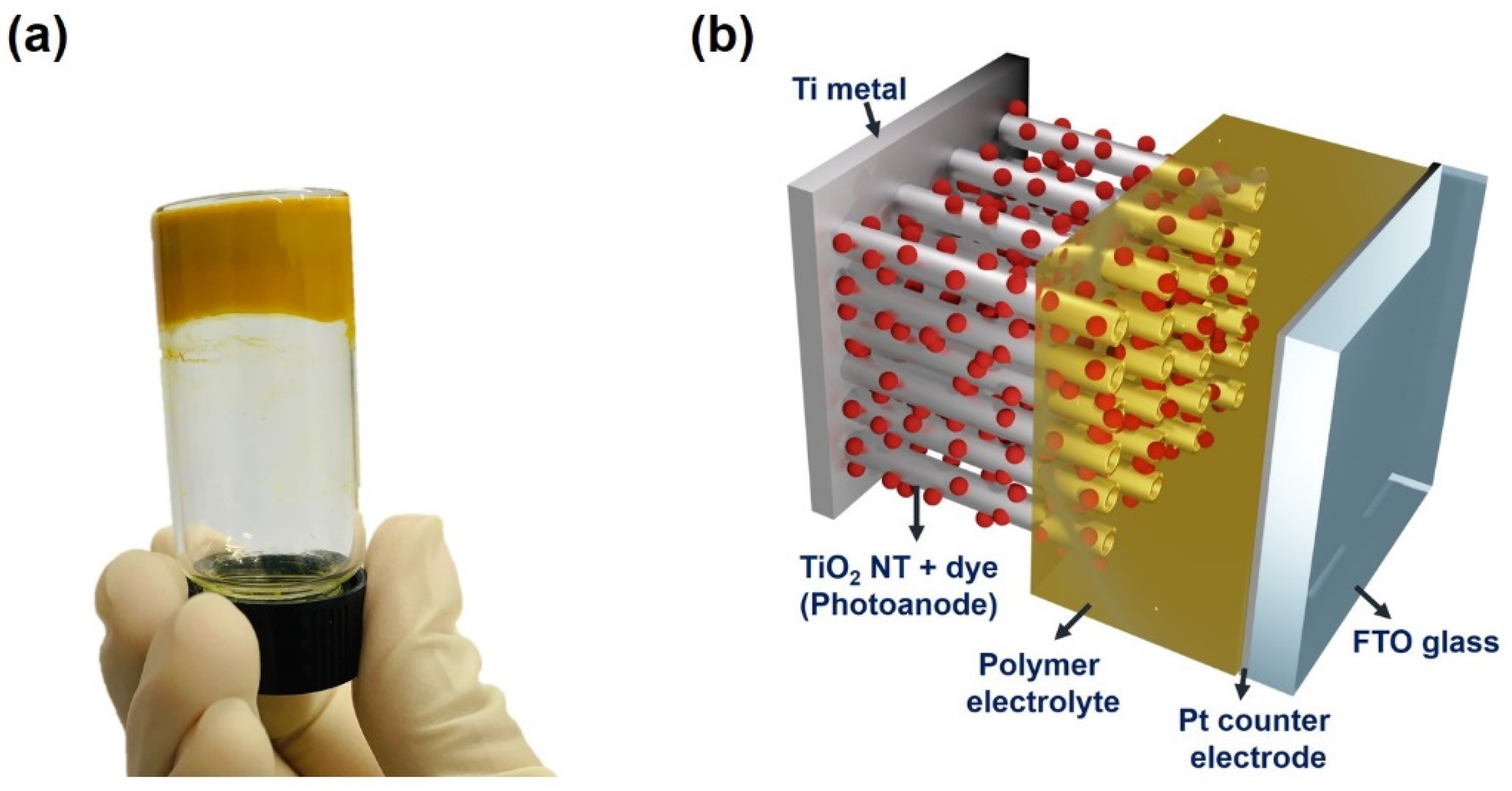
The prepared NT electrodes were applied in the quasi-solid-state DSSCs as photoanodes, as depicted in Figure 3. As shown in Figure 3a, a viscous gel electrolyte based on PEO was utilized, which was deposited onto the surface of NT electrodes. In particular, the TiO2 nanopowders were mixed in the gel electrolyte, since they create voids and free space into which the redox couples can efficiently migrate [32]. As shown in Figure 3b, since the photoanode of the fabricated quasi-solid-state DSSC is opaque, back-illumination through the counter electrode was inevitable for the device’s operation.
Figure 4a shows the J-V characteristics from the illuminated state of the quasi-solid-state DSSCs employing the anodic TiO2 NT electrodes and the gel electrolyte. The resulting photovoltaic parameters are summarized in Table 1 according to the anodization time with the adsorbed amount of dye molecules for each electrode. The adsorbed amount of dye molecules was evaluated based on the UV-vis spectrum of each electrode (Figure S2 in the Supplementary Materials). For statistical significance, the J-V data were obtained from three different cells for each condition, and the average values are listed. The absolute conversion efficiencies listed in Table 1 are relatively lower compared to the conventional DSSCs [8,9,10,11,12,39], due to the loss of incident light by the Pt counter electrode and the gel electrolyte under backside illumination. The use of polymer gel electrolyte instead of the conventional liquid electrolyte is also disadvantageous in achieving high conversion efficiency. As the anodization time increased from 1 h to 2 h, the short-circuit photocurrent density (JSC) was notably enhanced from 5.91 mA/cm2 to 8.05 mA/cm2 because of the increased dye-loading. Though the anodization time increased by more than 2 h, the JSC was no longer enhanced. Furthermore, the open-circuit voltage (VOC) gradually decreased as the anodization time increased. As a result, the photoconversion efficiency of DSSCs was optimized at the anodization time of 2 h.
The gradual decrease in VOC and the saturation of JSC at the anodization time of 2 h resulted from the increased electron recombination rate for the longer NT arrays. Firstly, the number of recombination centers on the surface of the NT electrode is greater for the longer NT arrays because of the enhanced roughness factor, leading to an increased electron recombination rate between the NT electrodes and the electrolyte [16,33]. This increased electron recombination can lead to the reduced VOC and JSC. In addition, as listed in Table 1, although the absolute amount of dye-loading was higher for the longer NT arrays, the dye-loading per unit length of NT array was smaller for the longer NT arrays. The adsorbed amounts of dye per unit length (1 μm) of the NT arrays were 6.8, 6.6, 5.7, and 4.8 × 10⁻⁹ mol cm−2 for 1, 2, 3, and 4 h samples, respectively. This result implies that the dye molecules are more densely adsorbed on the surface of shorter NT arrays, perhaps due to a partial bundling that appears in the long NT arrays [16,18]. Since the adsorbed dye molecules suppress the interfacial electron recombination between the photoanode and redox couples in the electrolyte [8], the electron recombination rate may be intrinsically slower for the shorter NT arrays, resulting in a relatively higher VOC.
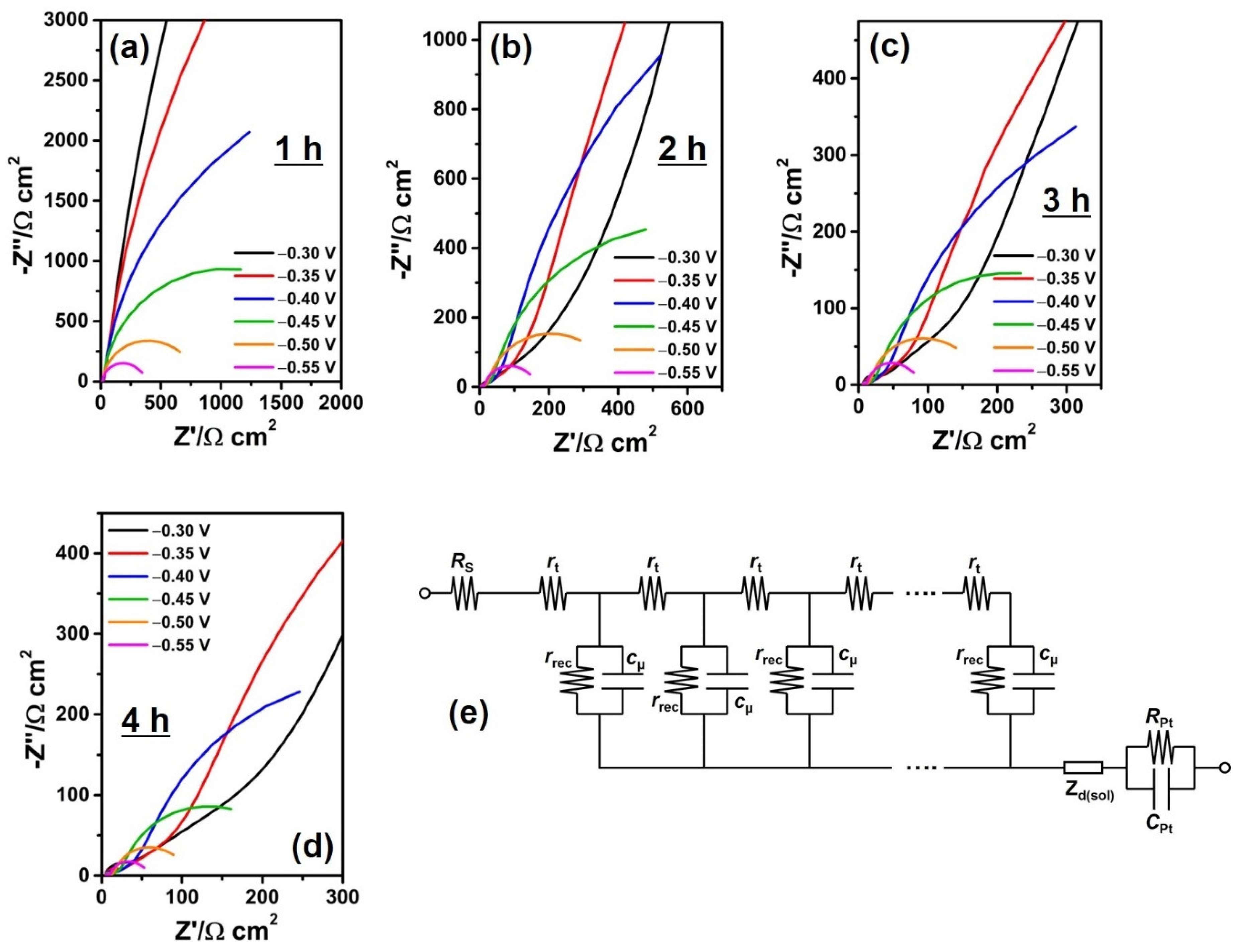
Quantitative analysis of the electron recombination at the photoanode depending on NT length was carried out by EIS. Figure 5 shows Nyquist plots of DSSCs according to anodization time, achieved at bias potentials ranging between −0.30 and −0.55 V in dark states. This potential range was selected to obtain both electron transport and recombination properties for the NT electrodes in DSSCs. The impedance parameters were obtained from these plots by fitting data with ZView software. Figure 5e shows the equivalent circuit model used for the fitting of impedance spectra according to the previous studies [18,40,41,42]. It is composed of series resistance (RS), and the resistances and chemical capacitances at the interface between the Pt counter electrode and gel electrolyte (RPt and CPt). The distributed components of the transmission line are the electron recombination resistance (rrec), the chemical capacitance (cμ), and the electron transport resistance (rt) of the NT electrode. These distributed parameters are related to the total resistances and chemical capacitances by rrec = RrecAd, cμ = Cμ/(Ad), and rt = RtA/d where A and d are the active area and the thickness of NT electrodes, respectively [41]. In addition, Warburg impedance (Zd) represents the diffusion of redox couples in the gel electrolyte.
The obtained rt, Rct, and Cμ values are plotted in Figure 6 as functions of bias potentials. The rt values were evaluated from the linear line in the high-frequency region at bias potentials ranging between −0.30 and −0.50 V [18,40,41,42,43]. In addition, the Rct and Cμ values were evaluated from the semicircle in the intermediate frequency region at bias potentials ranging between −0.35 and −0.55 V.
The rt was similar for the samples of 2~4 h anodization time; however, it was obviously lower for the shortest NT arrays (1 h). This result is in accord with the previous report [44]. It was found that the thicker photoanode in DSSCs exhibit a slower electron transport rate under backside illumination. Since most photoelectrons are generated near the electrolyte side and move by trap-limited diffusion under backside illumination, the thicker electrode is disadvantageous to fast electron transport.
The Rct apparently and gradually reduced as the NT length increased (Figure 6b), indicating that the electron recombination rate was higher for the longer NT arrays. This result is in good agreement with the trend of J-V characteristics from the dark states. As shown in Figure 6c, the Cμ enlarged as the anodization time increased, resulting from the increased surface area for electrochemical double-layer formation. Considering the gradual increase in Cμ as the NT length extended up to 41.7 μm, it is reasonable that the gel electrolyte permeated the entire thickness of these long NT arrays. This result indicates that the decrease in photoconversion efficiency for the long NT arrays is mainly attributed to the increased electron recombination rate at the interface of photoanode/electrolyte.
The electron recombination at the surface of NT arrays can be controlled by surface modification. For instance, wide band gap semiconductors such as Al2O3 [33], ZnO [31,34], SrTiO3 [35], etc., can be coated on the surface of TiO2 electrodes by using solution-based methods or vacuum processes. It has been reported that these wide band gap semiconductors passivate the TiO2 electrode surface and reduce the electron recombination in the conventional DSSCs that employ the liquid electrolyte. Based on the results obtained in this work, it can be expected that these approaches will also be effective for the quasi-solid-state DSSCs.

4. Conclusions

In summary, we prepared vertically aligned and highly ordered TiO2 NT electrodes via a two-step anodization method for application in quasi-solid-state DSSCs as a photoanode. In particular, the length of NT arrays is controlled by varying the anodization time. As the NT length increased from 9.7 to 18.5 μm, the photovoltaic properties were enhanced; however, a further increase in NT length led to a decrease in photoconversion efficiency. The EIS analysis reveals that the electron transport rate was similar in the 18.5 μm NT arrays and other longer NT arrays. The decreased photoconversion efficiency for the NT arrays longer than 18.5 μm was mainly attributed to the increased electron recombination with the redox couples in the polymer gel electrolyte. These results imply that the control of electron recombination on the surface of the NT electrode is strongly required to realize highly efficient quasi-solid-state DSSCs.

Supplementary Materials

The following are available online at https://www.mdpi.com/1996-1073/13/22/6100/s1, Figure S1: XRD patterns of the annealed TiO2 NT electrodes prepared by anodization for 1 and 4 h, Figure S2: UV–vis spectra of desorbed N-719 dye solution in 1 M NaOH aqueous solution for the anodic TiO2 NT electrodes depending on the anodization time.

Author Contributions

Conceptualization, J.-Y.K.; methodology, A.R.L. and J.-Y.K.; software, J.-Y.K.; validation, A.R.L. and J.-Y.K.; formal analysis, A.R.L. and J.-Y.K.; investigation, A.R.L. and J.-Y.K.; resources, J.-Y.K.; data curation, A.R.L. and J.-Y.K.; writing—original draft preparation, A.R.L. and J.-Y.K.; writing—review and editing, J.-Y.K.; supervision, J.-Y.K.; project administration, J.-Y.K.; funding acquisition, J.-Y.K. All authors have read and agreed to the published version of the manuscript.

Funding

The present research was supported by the research fund of Dankook University in 2019.

Conflicts of Interest

The authors declare no conflict of interest.

References

  1. O’Regan, B.; Grätzel, M. A low-cost, high-efficiency solar cell based on dye-sensitized colloidal TiO2 films. Nature 1991, 353, 737–740. [Google Scholar] [CrossRef]
  2. Lee, M.M.; Joël, T.; Tsutomu, M.; Murakani, T.N.; Snaith, H.J. Efficient hybrid solar cells based on meso-superstructured organometal halide perovskites. Science 2012, 338, 643–647. [Google Scholar] [CrossRef] [PubMed] [Green Version]
  3. Kim, B.-M.; Lee, M.-H.; Dilimon, V.S.; Kim, J.S.; Nam, J.S.; Cho, Y.-G.; Noh, H.K.; Roh, D.-H.; Kwon, T.-H.; Song, H.-K. Indoor-light-energy-harvesting dye-sensitized photo-rechargeable battery. Energy Environ. Sci. 2020, 13, 1473–1480. [Google Scholar] [CrossRef]
  4. Jiang, H.; Ren, Y.; Zhang, W.; Wu, Y.; Socie, E.C.; Carlsen, B.I.; Moser, J.-E.; Tian, H.; Zakeeuddin, S.M.; Zhu, W.-H.; et al. Phenanthrene-fused-quinoxaline as a key building block for highly efficient and stable sensitizers in copper-electrolyte-based dye-sensitized solar cells. Angew. Chem. Int. Ed. 2020, 59, 9324–9329. [Google Scholar] [CrossRef] [PubMed]
  5. Rajaramanan, T.; Natarajan, M.; Ravirajan, P.; Senthilnanthanan, M.; Velauthapillai, D. Ruthenium (Ru) doped titanium dioxide (P25) electrode for dye sensitized solar cells. Energies 2020, 13, 1532. [Google Scholar] [CrossRef] [Green Version]
  6. Chou, J.-C.; Ko, C.-C.; Chang, J.-X.; Lai, C.-H.; Nien, Y.-H.; Kuo, P.-Y.; Chen, H.-H.; Hsu, H.-H.; Hu, G.-M. Dye-sensitized solar cells using aluminum-doped zinc oxide/titanium dioxide photoanodes in parallel. Energies 2019, 12, 3469. [Google Scholar] [CrossRef] [Green Version]
  7. Cooper, C.B.; Beard, E.J.; Vázquez-Mayagoitia, Á.; Stan, L.; Stenning, G.B.G.; Nye, D.W.; Vigil, J.A.; Tomar, T.; Jia, J.; Bodedla, G.B.; et al. Design-to-device approach affords panchromatic co-sensitized solar cells. Adv. Energy Mater. 2018, 9. [Google Scholar] [CrossRef] [Green Version]
  8. Hagfeldt, A.; Boschloo, G.; Sun, L.; Kloo, L.; Pettersson, H. Dye-sensitized solar cells. Chem. Rev. 2010, 11, 6595–6663. [Google Scholar] [CrossRef]
  9. Yoo, K.; Kim, J.-Y.; Lee, J.A.; Kim, J.S.; Lee, D.-K.; Kim, K.; Kim, J.Y.; Kim, B.S.; Kim, H.; Kim, W.M.; et al. Completely transparent conducting oxide-Free and flexible dye-sensitized solar cells fabricated on plastic substrates. ACS Nano 2015, 9, 3760–3771. [Google Scholar] [CrossRef]
  10. Kim, J.-Y.; Kang, S.H.; Kim, H.S.; Sung, Y.-E. Preparation of highly ordered mesoporous Al2O3/TiO2 and its application in dye-sensitized solar cells. Langmuir 2010, 26, 2864–2870. [Google Scholar] [CrossRef]
  11. Lee, M.-W.; Kim, J.-Y.; Lee, H.-G.; Cha, H.G.; Lee, D.-H.; Ko, M.J. Effects of structure and electronic properties of D-π-A organic dyes on photovoltaic performance of dye-sensitized solar cells. J. Energy Chem. 2021, 54, 208–216. [Google Scholar] [CrossRef]
  12. Kang, J.S.; Choi, H.C.; Kim, J.; Park, H.; Kim, J.-Y.; Choi, J.-W.; Yu, S.-H.; Lee, K.J.; Kang, Y.S.; Park, S.H.; et al. Multidimensional anodized yitanium foam photoelectrode for efficient utilization of photons in mesoscopic solar cells. Small 2017. [Google Scholar] [CrossRef]
  13. Mor, G.K.; Shankar, K.; Paulose, M.; Varghese, O.K.; Grimes, C.A. Use of highly-ordered TiO2 nanotube arrays in dye-sensitized solar cells. Nano Lett. 2006, 6, 215–218. [Google Scholar] [CrossRef] [PubMed]
  14. Zhu, K.; Neale, N.R.; Miedaner, A.; Frank, A.J. Enhanced charge-collection efficiencies and light scattering in dye-sensitized solar cells using oriented TiO2 nanotubes arrays. Nano Lett. 2007, 7, 69–74. [Google Scholar] [CrossRef] [PubMed]
  15. Zhu, K.; Vinzant, T.B.; Neale, N.R.; Frank, A.J. Removing structural disorder from TiO2 oriented nanotube arrays:  reducing the dimensionality of transport and recombination in dye-sensitized solar cells. Nano Lett. 2007, 7, 3739–3746. [Google Scholar] [CrossRef] [PubMed]
  16. Kim, J.-Y.; Shin, J.Y.; Kim, D.H.; Sung, Y.-E.; Ko, M.J. Long vertically aligned TiO2 nanotube electrodes prepared via two-step anodization for highly efficient photovoltaics. Isr. J. Chem. 2015, 55, 1034–1040. [Google Scholar] [CrossRef]
  17. Kim, J.-Y.; Shin, K.-Y.; Raza, M.H.; Pinna, N.; Sung, Y.-E. Vertically aligned TiO2ZnO nanotube arrays prepared by atomic layer deposition for photovoltaic applications. Korean J. Chem. Eng. 2019, 36, 1157–1163. [Google Scholar] [CrossRef]
  18. Kim, J.-Y.; Lee, K.J.; Kang, S.H.; Shin, J.; Sung, Y.-E. Enhanced photovoltaic properties of a cobalt bipyridyl redox electrolyte in dye-sensitized solar cells employing vertically aligned TiO2 nanotube electrodes. J. Phys. Chem. C 2011, 115, 19979–19985. [Google Scholar] [CrossRef]
  19. Kim, J.-Y.; Lee, K.-H.; Shin, J.; Park, S.H.; Kang, J.S.; Han, K.S.; Sung, M.M.; Pinna, N.; Sung, Y.-E. Highly ordered and vertically oriented TiO2/Al2O3 nanotube electrodes for application in dye-sensitized solar cells. Nanotechnology 2014, 25. [Google Scholar] [CrossRef]
  20. Kuang, D.; Brillet, J.; Chen, P.; Takata, M.; Uchida, S.; Miura, H.; Sumioka, K.; Zakeeruddin, S.M.; Grätzel, M. Application of highly ordered TiO2 nanotube arrays in flexible dye-sensitized solar cells. ACS Nano 2008, 2, 1113–1116. [Google Scholar] [CrossRef]
  21. Jin, L.N.; Qian, X.Y.; Wang, J.G.; Aslan, H.; Dong, M. MIL-68 (In) nano-rods for the removal of Congo red dye from aqueous solution. J. Colloid Interface Sci. 2015, 453, 270–275. [Google Scholar] [CrossRef] [PubMed]
  22. Kang, S.H.; Kim, J.-Y.; Kim, Y.; Kim, H.S.; Sung, Y.-E. Surface modification of stretched TiO2 nanotubes for solid-state dye-sensitized solar cells. J. Phys. Chem. C 2007, 111, 9614–9623. [Google Scholar] [CrossRef]
  23. Stergiopoulos, T.; Ghicov, A.; Likodimos, V.; Tsoukleris, D.S.; Kunze, J.; Schmuki, P.; Falaras, P. Dye-sensitized solar cells based on thick highly ordered TiO2 nanotubes produced by controlled anodic oxidation in non-aqueous electrolytic media. Nanotechnology 2008, 19. [Google Scholar] [CrossRef] [PubMed]
  24. Chen, P.; Brillet, J.; Bala, H.; Wang, P.; Zakeeruddin, S.M.; Grätzel, M. Solid-state dye-sensitized solar cells using TiO2 nanotube arrays on FTO glass. J. Mater. Chem. 2009, 19, 5325–5328. [Google Scholar] [CrossRef]
  25. Pugliese, D.; Lamberti, A.; Bella, F.; Sacco, A.; Bianco, S.; Tresso, E. TiO2 nanotubes as flexible photoanode for back-illuminated dye-sensitized solar cells with hemi-squaraine organic dye and iodine-free transparent electrolyte. Org. Electron. 2014, 15, 3715–3722. [Google Scholar] [CrossRef]
  26. Seidalilir, Z.; Malekfar, R.; Wu, H.-P.; Shiu, J.-W.; Diau, W.-G. High-performance and stable gel-state dye-sensitized solar cells using anodic TiO2 nanotube arrays and polymer-based gel electrolytes. ACS Appl. Mater. Interfaces 2015, 7, 12731–12739. [Google Scholar] [CrossRef]
  27. Krumpmann, A.; Dervaux, J.; Derue, L.; Douhéret, O.; Lazzaroni, R.; Snyders, R.; Decroly, A. Influence of a sputtered compact TiO2 layer on the properties of TiO2 nanotube photoanodes for solid-state DSSCs. Mater. Des. 2017, 120, 298–306. [Google Scholar] [CrossRef]
  28. Xiao, B.-C.; Lin, L.-Y. Tuning electrolyte configuration and composition for fiber-shaped dye-sensitized solar cell with poly (vinylidene fluoride-co-hexafluoropropylene) gel electrolyte. J. Colloid Interface Sci. 2020, 571, 126–133. [Google Scholar] [CrossRef]
  29. Praveen, E.; Peter, I.J.; Kumar, A.M.; Ramachandran, K.; Jayakumar, K. Boosting of power conversion efficiency of 2D ZnO nanostructures-based DSSC by the Lorentz force with chitosan polymer electrolyte. J. Inorg. Organomet. Polym. Mater. 2020, 30. [Google Scholar] [CrossRef]
  30. Selvanathan, V.; Yahya, R.; Alharbi, H.F.; Alharthi, N.H.; Alharthi, Y.S.; Ruslan, M.H.; Amin, N.; Akhtaruzzaman, M. Organosoluble starch derivative as quasi-solid electrolytes in DSSC: Unravelling the synergy between electrolyte rheology and photovoltaic properties. Sol. Energy 2020, 197, 144–153. [Google Scholar] [CrossRef]
  31. Galliano, S.; Bella, F.; Bonomo, M.; Viscardi, G.; Gerbaldi, C.; Boschloo, G.; Barolo, C. Hydrogel electrolytes based on xanthan gum: Green route towards stable dye-sensitized solar cells. Nanomaterials 2020, 10, 1585. [Google Scholar] [CrossRef] [PubMed]
  32. Stergiopoulos, T.; Arabatzis, I.M.; Katsaros, G.; Falaras, P. Binary Polyethylene oxide/titania solid-state redox electrolyte for highly efficient nanocrystalline TiO2 photoelectrochemical cells. Nano Lett. 2002, 2, 1259–1261. [Google Scholar] [CrossRef]
  33. Ghicov, A.; Albu, S.P.; Hahn, R.; Kim, D.; Stergiopoulos, T.; Kunze, J.; Schiller, C.-A.; Falaras, P.; Schmuki, P. TiO2 nanotubes in dye-sensitized solar cells: Critical factors for the conversion efficiency. Chem. Asian J. 2009, 4, 520–525. [Google Scholar] [CrossRef] [PubMed]
  34. Nazeeruddin, K.M.; Zakeeruddin, S.M.; Humphry-Baker, R.; Jirousek, M.; Liska, P.; Vlachopoulos, N.; Shklover, V.; Fischer, C.-H.; Grätzel, M. Acid−base equilibria of (2,2‘-Bipyridyl-4,4‘-dicarboxylic acid)ruthenium(II) complexes and the effect of protonation on charge-transfer sensitization of nanocrystalline titania. Inorg. Chim. 1999, 38, 6298–6305. [Google Scholar] [CrossRef]
  35. Lenzmann, F.; Krueger, J.; Burnside, S.; Brooks, K.; Grätzel, M.; Gal, D.; Rühle, S.; Cahen, D. Surface photovoltage spectroscopy of dye-sensitized solar cells with TiO2, Nb2O5, and SrTiO3 nanocrystalline photoanodes:  Indication for electron injection from higher excited dye states. J. Phys. Chem. B 2001, 105, 6347–6352. [Google Scholar] [CrossRef]
  36. Ziółek, M.; Cohen, B.; Yang, X.; Sun, L.; Paulose, M.; Varghese, O.K.; Grimes, C.A.; Douhal, A. Femtosecond to millisecond studies of electron transfer processes in a donor- (π-spacer)–acceptor series of organic dyes for solar cells interacting with titania nanoparticles and ordered nanotube array films. Phys. Chem. Chem. Phys. 2012, 14, 2816–2831. [Google Scholar] [CrossRef]
  37. Zukalová, M.; Procházka, J.; Zukal, A.; Yum, J.H.; Kavan, L. Structural parameters controlling the performance of organized mesoporous TiO2 films in dye sensitized solar cells. Inorg. Chim. Acta 2008, 361, 656–662. [Google Scholar] [CrossRef]
  38. Fang, K.; Yang, Y.; Fu, L.; Zheng, H.; Yuan, J.; Niu, L. Highly selective H2O2 sensor based on 1-D nanoporous Pt@C hybrids with core–shell structure. Sen. Actuators B 2014, 191, 401–407. [Google Scholar] [CrossRef]
  39. Wang, Z.; Li, P.; Chen, Y.; He, J.; Zhang, W.; Schmidt, O.G.; Li, Y. Pure thiophene–sulfur doped reduced graphene oxide: Synthesis, structure, and electrical properties. Nanoscale 2014, 6, 7281–7287. [Google Scholar] [CrossRef] [Green Version]
  40. Fabregat-Santiago, F.; Bisquert, J.; Garcia-Belmonte, G.; Boschloo, G.; Hagfeldt, A. Influence of electrolyte in transport and recombination in dye-sensitized solar cells studied by impedance spectroscopy. Sol. Energy Mater. Sol. Cells 2005, 87, 117–131. [Google Scholar] [CrossRef]
  41. Jennings, J.R.; Liu, Y.; Safari-Alamuti, F.; Wang, Q. Dependence of dye-sensitized solar cell impedance on photoelectrode thickness. J. Phys. Chem. C 2012, 116, 1556–1562. [Google Scholar] [CrossRef]
  42. Qiu, J.; Zhuge, F.; Lou, K.; Li, X.; Gao, Z.; Gan, X.; Yu, W.; Kim, H.-K.; Hwang, Y.-H. A facile route to aligned TiO2 nanotube arrays on transparent conducting oxide substrates for dye-sensitized solar cells. J. Mater. Chem. 2011, 21, 5062–5068. [Google Scholar] [CrossRef]
  43. Wang, Z.; Liu, J.; Hao, X.; Wang, Y.; Chen, Y.; Li, P. Enhanced power density of a supercapacitor by introducing 3D-interfacial graphene. New J. Chem. 2020, 44, 13377–13381. [Google Scholar] [CrossRef]
  44. Hsiao, P.T.; Liou, Y.J.; Teng, H. Electron transport patterns in TiO2 nanotube arrays based dye-sensitized solar cells under frontside and backside illuminations. J. Phys. Chem. C 2011, 115, 15018–15024. [Google Scholar] [CrossRef]
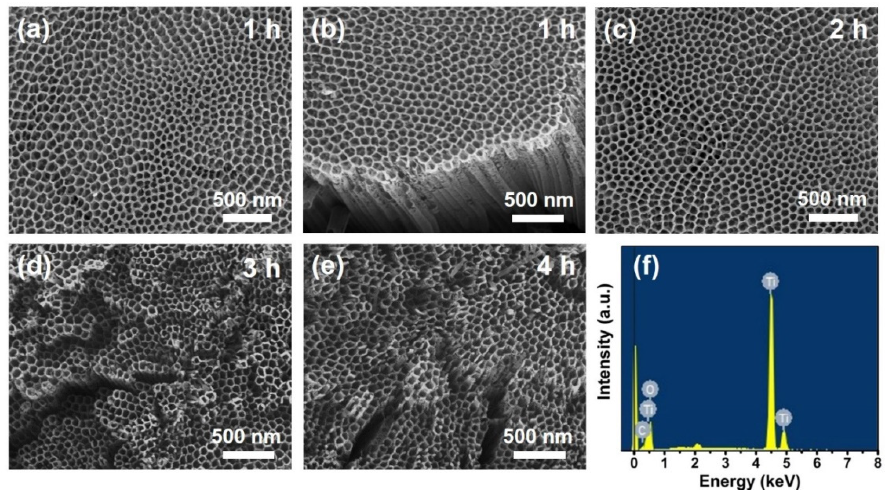
Figure 1. (ae) Top-view of FE-SEM images of the annealed anodic TiO2 nanotube (NT) electrodes prepared by anodization for 1–4 h, and (f) quantitative surface composition for (a).
Energies 13 06100 g001
Figure 2. (ad) Side-view of FE-SEM images of the annealed anodic TiO2 NT electrodes prepared by anodization for 1–4 h.
Energies 13 06100 g002
Figure 3. (a) Photograph of PEO-based polymer electrolyte in a glass vial, and (b) schematic device structure of the quasi-solid-state dye-sensitized solar cells (DSSC) employing an anodic TiO2 NT electrode.
Energies 13 06100 g003
Figure 4. (a) Photocurrent density–voltage (J-V) characteristic curves in (a) illuminated (light intensity: 100 mW/cm2; AM 1.5 G conditions); and (b) dark states of the quasi-solid-state DSSCs based on the anodic TiO2 NT electrodes depending on the anodization time.
Energies 13 06100 g004
Figure 5. (ad) Impedance spectra obtained at bias potentials of −0.30 to −0.55 V for the quasi-solid-state DSSCs based on the anodic TiO2 NT electrodes depending on the anodization time, and (e) the equivalent circuit model for the analysis of impedance spectra.
Energies 13 06100 g005
Figure 6. (a) Electron transport resistance, (b) recombination resistance, and (c) chemical capacitance for the anodic TiO2 NT electrodes depending on the anodization time, evaluated from the impedance spectra.
Energies 13 06100 g006
Table 1. Photovoltaic parameters of the dependence on the anodization time for the anodic TiO2 NT electrodes.
Anodization TimeJSC (mA/cm2)VOC (mV)FFη (%)Adsorbed Amount of Dye (×10−8 mol cm−2)
1 h5.91 ± 0.21539 ± 455.0 ± 2.11.75 ± 0.096.6
2 h8.05 ± 0.24523 ± 652.1 ± 1.22.19 ± 0.0812.3
3 h7.61 ± 0.30503 ± 351.7 ± 0.61.98 ± 0.0516.7
4 h7.48 ± 0.57479 ± 653.7 ± 3.71.92 ± 0.0120.2
Publisher’s Note: MDPI stays neutral with regard to jurisdictional claims in published maps and institutional affiliations.