Abstract
Renewable energy is expected to experience epic growth in the coming decade, which is reflected in the record new installations since 2010. Wind energy, in particular, has proved its leading role among sustainable energy production means, by the accelerating rise in total installed capacity and by its consistently increasing trend. Taking a closer look at the history of wind power development, it is obvious that it has always been a matter of engineering taller turbines with longer blades. An increase in the tower height means an increase in the material used, thereby, impacting the initial construction cost and the total energy consumed. In the present study, a numerical investigation is carried out in order to actively compare conventional cylindrical shell towers with lattice towers in terms of material use, robustness and environmental impact. Lattice structures are proved to be equivalently competitive to conventional cylindrical solutions since they can be designed to be robust enough while being a much lighter tower in terms of material use. With detailed design, lattice wind turbine towers can constitute the new generation of wind turbine towers.
1. Introduction
Towards a clean energy future, the reduction of carbon emissions for climate change mitigation has been the key factor of the International Renewable Energy Agency agenda [1]. Some of the most catastrophic natural events are attributed to global warming and the consequences of the greenhouse effect. Sustainable energy production is critical in order to preserve current climate conditions and limit the environmental pollutants from the burning of fossil fuels. Global energy demand is constantly growing, and therefore the implementation of sustainable energy production is considered imperative; a fact that is evidently reflected in the contemporary European Commission Directive, setting a target of 27% total energy consumption coming from renewables by the end of 2030 [2]. Wind energy, due to its infinite nature and great potential, has shown great expansion between renewables in the last decade. Wind power indicatively accounts for 18.8% of the European Union’s (EU) total installed power-generation capacity [3], with the total number of European wind park installations tripling from about 50 GW in 2005 to more than 150 GW in 2016 [4]. When decisions for energy-system investment are made, all aspects of planning, development and construction are taken into account when assessing different solutions [5], and having in mind that the tower of a wind turbine constitutes more than 25% of the initial construction cost [6], designers should focus on constructing a robust structure with minimized costs. Aiming towards a zero-carbon economy and focusing on reducing initial construction costs, makes the reduction of total material use on wind turbine tower design a key parameter in contemporary wind generator design in general. The investigation and comparative analysis carried out in the present work focuses on the assessment of two different onshore wind turbine tower structural configurations at different heights. The aim of the present paper is to provide a tower solution with minimized initial construction cost by limiting the material use, both in the upper structure and the foundation, while providing structural integrity and robust design. Since three quarters of the new wind installation in Europe were onshore [7], the current investigation is focused on optimizing the structural configuration for horizontal axis onshore wind converters. The tower configurations more frequently seen in horizontal axis onshore wind converters are: the tubular tower, the lattice tower, and the hybrid tower—meaning the combination of a truss structure for the lower part and a tube for the upper one; and the material most commonly used for achieving lighter structures is steel. The prevailing structural configuration of the total installed wind capacity is the steel tubular tower, providing the advantage of robust structural design, prefabrication of large wind tower parts, limited on-site labor and easier mounting between parts. Cylindrical shells are traditionally preferred by designers in order to minimize material use in structures, because due to their geometry they are capable of carrying great loads with small shell thicknesses.
The tubular wind turbine tower construction procedure offers certain advantages since a big part of the process takes place in the factory where large thick plates are curved to constitute shell rings which are welded consecutively in order to form tower subparts. These tapered steel tower subparts manufactured in the factory are transported to the site and mounted to their final positions by means of bolted flanges with the use of pretensioned bolts [8]. Wind farms constitute large-scale civil engineering projects, and therefore wind turbine tower structural analysis is perceived of ultimate importance, since structural failure can result in human losses along with a great economic impact. Tubular shell towers are designed as cantilevered structures, mainly against buckling, with the governing loads of their design being the wind pressure along the tower, the moment and lateral load due to rotor operation, and the vertical load of the rotor weight. Buckling behavior of cylindrical shells has been thoroughly investigated in the past, both numerically and experimentally, by a great number of research groups, such as Timoshenko and Gere [9], Bazant and Cedolin [10] and Teng and Rotter [11]. Baniotopoulos et al. [12] has performed specialized research on the structural analysis and response of tubular steel towers against wind loading while Lee and Bang [13] have developed a numerical model and performed an elaborate analysis simulating with great accuracy the collapse of a real wind turbine tower by a lightning strike. Increased power demands require taking advantage of the higher wind energy potential at greater heights, and therefore contemporary wind energy structures need to be constructed taller and with longer blades. For conventional tubular shell towers, an increase in height would directly mean an increase in the thickness of the tower shell and an increase in the tube diameter, resulting in increased material used for their construction and additional restrictions in tower subpart transportation. In order to minimize the material use while increasing tower heights, several research groups have focused on the introduction of stiffeners inside tubular structures, like the work performed by Dimopoulos and Gantes [14,15], Rebelo et al. [16,17] and Stavridou et al. [18,19]. The minimization of material use while retaining structural integrity has certain limitations in tubular steel structures with stiffeners, and therefore an alternative solution to material use minimization is the introduction of an alternative tower configuration, which is lighter and robust, like a lattice structure.
As already mentioned above, the tubular tower configuration functions as a simple cantilever structure, so an increase in height would result in an increase in the tower’s bottom diameter in order to sustain the great resisting moment at the base. Additional to increased material use in taller tubular structures, certain transportation limitations (e.g., the bridge span on highways etc.) prevent the towers from having greater diameters and longer subparts. When these kind of transportation limitations apply, a lattice tower would be an appealing solution for onshore wind turbine towers. Lattice towers have been extensively used for constructing telecommunication masts and have been thoroughly investigated against multiple types of loading like wind loading by Carril et al. [20], Harikrishna et al. [21] and Holmes [22,23,24], seismic loading by Khedr [25] and Khedr and McClure [26] and dynamic loading by Madugula [27]. The implementation of lattice towers as support structures for wind energy generators has only been introduced recently and the investigation of their structural response against multiple types of loading has been the work of Gencturk et al. [28], Long and Moe [29], Long et al. [30] and Zwick et al. [31].Very limited work has been devoted in the optimization of lattice tower design, opening the field for the high-quality and original work conducted in the present paper.
Lattice towers offer the advantage of carrying great loads with a light-weight structure, which is done by configuring the towers using standard pre-fabricated cross-sections that are mounted on-site by means of bolted connections. The difficulty when introducing lattice structures as the supporting tower for wind turbines is that the scale of loads that they have to sustain require the use of cross-sections that are well outside the range of standard industrial profiles. The lattice tower examined and optimized in the present work has the form of a truncated cone with square base in order to be capable of accommodating the nacelle. The tower, being a statically determinate structure, is composed of different discrete structural subsystems that play a different role in the load-transfer mechanism; the legs, the bracing trusses on the faces (FBTs), horizontal braces and secondary bracings arranged inside the plane of the face bracing trusses (FBTs). As already mentioned above, the tower constitutes a statically determinate system, meaning that the axial stresses of all its structural components can be determined by closed-form expressions. The present paper addresses material use optimization that can be achieved in lattice towers of different heights by comparing them to the equivalent tubular steel towers. The structural performance of all towers is assessed so that they are robust enough but at the same time the total steel weight is calculated. The present work concludes in the fact that lattice structures have minimized material use maintaining their endurance and robustness, while when reaching greater heights, the material saving becomes even greater.
2. Materials and Methods
The numerical investigation carried out in the present work refers to two different wind turbine tower configurations, the tubular steel shell tower and the lattice one. Two different tower heights are investigated in each configuration. The software used to calculate the structural response of the structures against combined loading conditions is the general-purpose finite element software Abaqus [32]. The tubular tower models are validated in comparison to already constructed towers and previous work carried out by the research group, while the lattice tower model has been validated in comparison to an optimization analysis and parametric study performed in the general purpose mathematical software, Mathematica [33]. For the parametric study all relevant design codes and guidelines were followed.
2.1. Tubular Tower Configuration
As already mentioned, there are two tubular towers of different heights under investigation. There are two tubular, steel wind turbine towers designed for implementation as horizontal axis, onshore structures and they have been examined in the Histwin project [34]. Both steel shell towers are fabricated in the factory by welding tubular shell rings of increasing shell thickness going from top to bottom of the tower. In order to facilitate transportation and mounting, the towers are divided in subparts of 20 to 30 m that are connected to each other by means of bolted flanges, with the use of pre-stressed bolts. Tower_T_A, as it will be referred to hereafter, is a 76.20 m high tubular tower which consists of three subparts of 21.8, 26.6 and 27.8 m as can be observed in Figure 1a. Tower_T_B is a 105 m high tubular tower which consists of four subparts of 22.6, 27.12, 27.52 and 27.76 m as presented in Figure 1b. Both structures are of increasing shell thickness and tower diameter along their height when going from top to bottom of the structure. For transportation purposes under highway bridges most of the time, tubular tower diameters very rarely exceed 4.5 m. For the case of the two towers under investigation, the bottom diameter is 4.3 m, and the tower shell ends at a flange which is embedded in the reinforced concrete foundation by pre-stressed anchor bolts.
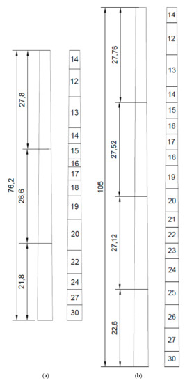
Figure 1.
Tubular tower configurations: (a) Tower_T_A shell thickness distribution; (b) Tower_T_B shell thickness distribution.
As far as the shell towers are concerned, the four-noded, doubly curved, reduced integration shell element of type S4R, as described in the Abaqus software manual [32], are used. These types of elements have already been used in similar structures modelling [35,36] giving accurate results. The model mesh was a product of a convergence study performed prior to the non-linear analysis. Tubular wind turbine towers are designed taking into account the self-weight of the rotor (WR), the shear force due to the rotor’s operation (QR), the moment due to the rotor’s operation, and the wind loading (MRW) as can be described in Equation (1) below.
Ftot = WR + QR+ MRW
In the present study, fatigue, seismic and icing loading as well as the weight of ancillary equipment and the maintenance platforms are neglected, and therefore only the towers’ overall behavior towards normal operating loads is assessed. The steel grade used is the same in all tubular and lattice structures and is described below. In order to accurately simulate the structure, the support of the structure and the top plate of the tower are introduced to the model with the use of appropriate boundary conditions and constraints. At the foundation, the degrees of freedom of all the nodes are constrained, simulating the fixed connection of the tower to the concrete foundation. The top plate, where the loads of the nacelle are acting on the tower, is simulated with a reference point at the centroid of the circle (master point) bonded with the nodes at the perimeter of the tower (secondary points) by means of kinematic coupling constraints. This simulation method constrains the nodes of the tower perimeter to the rigid body motion of a single node, the one at the centroid. The loads are acting on the master point and all the nodes of the top perimeter are acting as a diaphragm, sharing the same displacement with the master point. Cylindrical shells are vulnerable to buckling, and therefore local geometric imperfections are not to be neglected at their design. These initial imperfections are introduced into the models in the form of the elastic buckling mode shape that corresponds to the first eigenvalue. As Koiter [35] first introduced and Speicher and Saal [36] implemented on shell structures, the equivalent imperfection most suitable for the investigation of steel shells is of the same form as the first bifurcation mode and the imperfection amplitude is calculated according to paragraph 8.7 of Eurocode EN 1993-1-6 [37]. A non-linear static analysis, taking into account both material and geometric non-linearities, was carried out in the present study in order to calculate the structural response of the tubular wind turbine towers.
2.2. Lattice Tower Configuration
The lattice tower configuration has the form of a truncated cone with a square base and the tower is split in fragments along its height. The number of fragments is the output of a parametric analysis carried out in Mathematica software. The lattice tower examples have an identical height to the equivalent tubular structures examined in the present work. The truss towers under investigation are structurally determinate systems composed of discrete structural sub-systems; i.e., the legs, the bracing trusses on the faces, and the horizontal braces as shown in Figure 2a,b. In Figure 2a the 76.20 m high tower is depicted named Tower_L_A hereafter and in Figure 2b the 105 m high tower is depicted, named Tower_L_B hereafter.
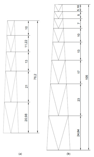
Figure 2.
Lattice towers configuration: (a) Tower_L_A configuration of 76.2 m; (b) Tower_L_B configuration of 105.0 m.
Each structural sub-system plays a distinct role in the load transfer mechanism of the tower with (a) the legs being responsible for transferring the axial load from the nacelle weight and the moment deriving from the horizontal shear and top-moment imported to the lattice structure at its top by the connecting plate of the nacelle; (b) the FBT being responsible for transferring the horizontal shear; and (c) the horizontal braces being responsible for taking the out-of-plane buckling of the FBT elements. As already mentioned above, the fact that the lattice structure constitutes a structurally determinate system means that all the axial stresses of its structural components can be directly derived by closed-form expressions.
The lattice structure numerical analysis is performed using closed form expressions that are inherited in Mathematica software and, therefore, all the members are designed in their elastic area. The stresses developed in the members do not exceed the yielding point. The optimization code in Mathematica software is developed in the present work in order to provide the lattice solution that is properly designed according to Eurocode EN 1993-1-1 [38] provisions while minimizing the total material used. In the design of a certain structural member, the cross-section choice is of cylindrical shape and will result in a Nb,Rd equal to the design axial force NEd according to EN 1993-1-1 [38]. The problem of determining the diameter (D) and the thickness (t) of the most economical cross-section for the cylindrical members is solved in the script by setting the D/t ratio equal to the limiting value of Class III cross-sections—that is, 90 ε2 where ε is given by Equation (2) below.
The script mentioned above, developed in Mathematica software, is specialized in solving the structural optimization problem of square-based truss towers. The way it functions is by finding the diameter of the tubular cross-section that fulfils the buckling resistance of the member while minimizing the tower weight at the same time. The key components that need to be optimized are the horizontal and diagonal members of the face bracing trusses and the legs of the tower. Certain geometrical parameters need to be taken into account in order for the tower to be split in segments and for the parametric analysis to give accurate results. Among the different bracing system shapes available, given the fact that the tower is conical, the V-shaped FBT is more economical as it keeps the total length of the diagonal members less than the X brace and the inverted V brace. In the script there is a whole subroutine devoted to calculating the optimal angle of the diagonal members of the braces giving minimized tower weight. This angle of the diagonals is the decisive criterion on the number of segments that the tower needs to be split along its height, actually determining the buckling length of the tower legs. The structure, being structurally determinant, offers the advantage of calculating the normal force that develops in the legs of the tower from equilibrium considerations and closed form expressions. The axial force that develops at the legs of a square-base tower is maximized when the top shear acts in the direction of the diagonal of the tower. Therefore, the axial force is given by Equation (3):
where M(z) is the bending moment of a vertical cantilever, b(z) is a geometrical parameter correlating the top and base width and φd is the angle of the leg to the horizontal plane. For the purposes of the optimization script, a reference case is used where there is a constant leg cross-section from bottom to top and, therefore, constant axial force. The characteristic base width given by Equation (4) below is the one that keeps the axial force constant:
where Btop is the top width, Mtop is the moment at the top of the tower, H is the tower height and Ftop is the horizontal force acting at the top of the tower. When taking into account all the aforementioned parameters, the tower optimization problem is confined to the search space defined by the two independent variables: Btop and μ. The variable μ is a non-dimensional parameter that determines the deviation of the base width from the characteristic width and is given by Equation (5) below:
The total weight of the tower is determined by satisfying all the buckling checks for all the structural members as described in Eurocode EN 1993-1-1 [38]. Calculating the capacity of structural members against buckling is a highly non-linear procedure and is greatly influenced by the buckling length, which in turn is controlled in the present tower type by the introduction of secondary bracing. The optimal weight is not derived directly as a solution of Equation (4), but needs an iterative procedure to take into account and counterbalance the two antagonistic factors that determine the optimal tower design: (a) the parallel increase of the leg axial force along with the reduction of the face bracing weight, when closing the distance between the legs and (b) the parallel reduction of the leg axial force along with the total length and slenderness increase of the V braces, when increasing the distance between the legs. In the script a two-dimensional search is performed, in order to assess the variation of the total tower weight with respect to Btop and μ using successive iterations. The tower model with minimum weight is verified with the use of Abaqus [32] software. The tower structural members and the number of segments of the FBTs are determined from the iterative procedure that optimizes the tower weight with the V-brace angle diversity. The structural behavior of the tower is assessed through a numerical analysis, where the model elements are modelled with T3D2 truss elements and the tower joints are introduced to the model with the use of appropriate boundary conditions and constraints. At the foundation, the degrees of freedom of all the nodes are constrained, since the tower is considered fixed to its foundation. The design procedure introduced in the script is verified with the Abaqus model achieving very satisfying results.
2.3. Material
In order for our comparative analysis to be accurate, the material used for all lattice and tubular towers is identical with the steel grade used being that of type S355. The material properties incorporated into the finite-element models were based on the coupon tests performed in the Histwin project [34], in the form of an elastic–plastic multi-linear curve with the von Mises yield criterion and isotropic hardening. In the finite element software used, the material properties need to be input in the form of a multi-linear true stress–true plastic strain curve, and therefore the measured engineering stress–strain curves are converted into the true stress–true plastic strain curves by means of Equations (6) and (7),
where σeng is the engineering stress, εeng is the engineering strain, E is the Young’s modulus, σtrue is the true stress and is the logarithmic plastic strain. Hence, the material law introduced in the model consists of three branches, as observed in Figure 3; the first is an almost constant plateau until 0.011 true strain, the second is a steep branch until 0.0528 true strain and 539 MPa true stress, and the third is a smooth branch until ultimate plastic strain0.174% and ultimate true stress 612 MPa.
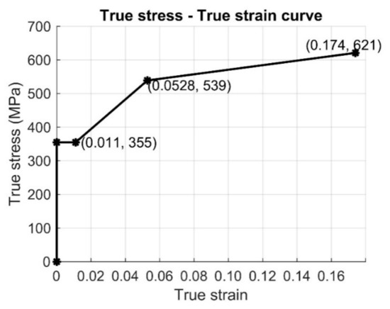
Figure 3.
Law incorporated in the present analyses.
3. Results
3.1. Tubular Tower Results
3.1.1. Initial Bifurcation Analysis
The first step for analyzing the structural behavior of the tubular towers, is an eigenmode analysis where the critical elastic buckling mode shape and the critical buckling load of the structures are calculated. Determining the buckling load of the tubular towers is critical in order to understand the maximum load that they can sustain before failure. Another critical element for the assessment of the structural behavior of steel shells is that by obtaining the eigenmode shape of the first eigenmode of the structure the introduction of initial imperfections in the numerical analysis can be accurately done with the use of the respective amplitude factor. The first three eigenmodes of the Tower_T_A are shown in Figure 4a,b and Figure 5 while the first three eigenmodes of the Tower_T_B are shown in Figure 6a,b and Figure 7.
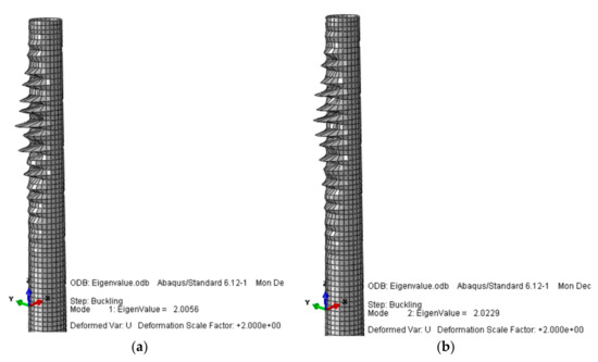
Figure 4.
Eigenmodes: (a) 1st Eigenmode; (b) 2nd Eigenmode.
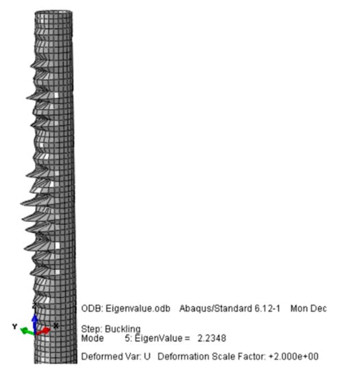
Figure 5.
Tower_T_A 3rd Eigenmode.
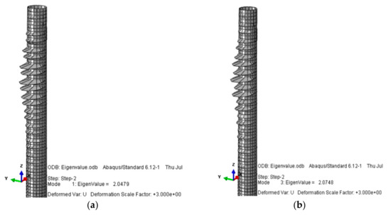
Figure 6.
Tower_T_B Eigenmodes: (a) 1st Eigenmode; (b) 2nd Eigenmode.
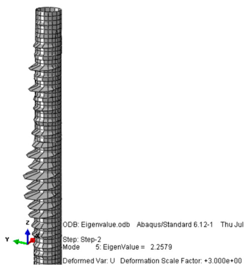
Figure 7.
Tower_T_B 3rd Eigenmode.
The short wavelength buckling shape that prevails in all the eigenmodes is characteristic of the dominant bending moment and compressive forces acting on the structure.
3.1.2. Non-Linear Analysis
As far as the non-linear analyses of the tubular towers are concerned, after using the first eigenmode of the bifurcation analyses of the two towers, material non-linear imperfection analyses are carried out and the results are presented in Figure 8 and Figure 9 for Tower_T_A and Tower_T_B, respectively. From the material non-linear imperfection analyses the towers’ response towards combined loading is obtained. The material properties are considered in terms of plastic true stress and plastic true strain, as described in the separate section above, and the stress concentration is observed at the top third of the tower, as expected. When taking into account the initial imperfections, the first eigenmode deformed shape is used with the amplification factor proposed in the Eurocode EN 1993-1-6 [37]. In the first eigenmode of both towers, the short wavelength buckles are dominant and they provoke more complicated deformations like ‘ovalization’ of the cross-section and long wavelength buckles of the circumference of the shell, as observed in the results of Figure 8 and Figure 9. In both towers the concentration of high von Mises stresses appears at the upper third of the structure. The ovalization of the tube at the area of high von Mises stresses concentration indicates the immense importance of initial imperfections to the final failure of the structure. The failure load of the structure appears to be one-fourth of the load indicated by the eigenvalue analysis. This phenomenon of shells that buckle at a lower ultimate load than that shown by the eigenvalue analysis is expected and has been described extensively in the cylindrical shells’ theory. As far as the total tower mass is concerned, the optimized Tower_T_A weighs 127.215 t (127,215 kg), while the optimized Tower_T_B weighs 190.005 t (190,005 kg).
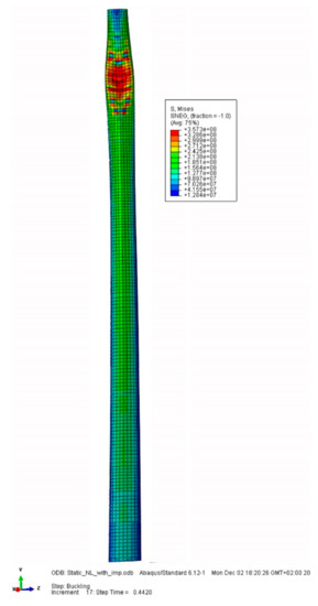
Figure 8.
Material non-linear imperfection analysis results for Tower_T_A.
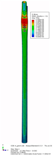
Figure 9.
Material non-linear imperfection analysis results for Tower_T_B.
3.2. Lattice Tower Results
3.2.1. Analysis of 76 m Tower
In order to perform the parametric analysis for the material optimization of the lattice structure, there are a total of 126 design cases built by combinations of Btop (350–1000 mm) and μ (0.65–1.3). In all 126 cases, the lattice tower height is constant and set to 76.2 m tall and the loading conditions are identical to the equivalent tubular one. The weight of the tower in correlation with the non-dimensional parameter μ and Btop is presented in Figure 10 for the total number of tower cases.
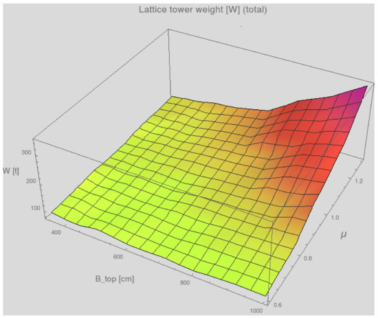
Figure 10.
Total weight of tower cases in correlation with μ and Btop for the 76 m towers.
In a general manner, the higher the top width and the greater the number of μ, the greater the tower weight. In more detail, the fluctuating tower weight for the different tower configuration cases is presented in Figure 11 and Figure 12, where the tower weight is plotted for each Btop and is presented in correlation to the non-dimensional parameter μ.
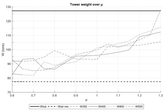
Figure 11.
Total weight of tower cases in correlation with μ and Btop for the 76 m towers.
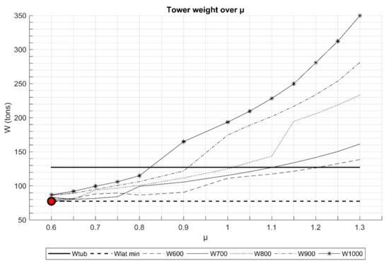
Figure 12.
Total weight of tower cases in correlation with μ and Btop for the 76 m towers.
As can be easily observed from Figure 11, for narrow top widths ranging from 350 to 500 mm, all the tower cases’ weight is lower than the tubular tower weight, independently of μ. In Figure 12 it is evident that for wider top widths, the weight of the tower does depend on the non-dimensional parameter μ, as for many cases with greater Btop and μ the lattice tower weight exceeds the tubular tower weight. In Figure 13, all towers of equal μ = 0.6 parameter are displayed. The weight of the tower is displayed with regards to the top width for the given number of μ and the weight is symbolized with W and W 0.6 corresponding to the weight of the tower for μ = 0.6.
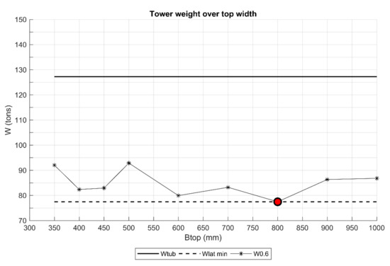
Figure 13.
Weight of tower cases for μ = 0.6 in correlation with Btop for the 76 m towers.
The optimized lattice tower has a weight of 77.47 t (77,470 kg) and is calculated for the model with Btop equal to 800 mm and μ equal to 0.6. The maximum tower weight for the lattice solution has a weight of 349.816 t. As already presented above, the face bracing trusses are of V shape. The total tower height is split in segments and the driving criterion for the separation of the tower is the angle of the diagonal members of V-braces, that in the case presented here is set to 45°. The optimal 76 m tower is split into five subparts with heights described in Table 1.

Table 1.
Lattice tower segment heights.
The lattice tower under investigation has a square base and all four faces consist of the same structural elements since the structure is designed to be symmetric and can be loaded with wind coming from any direction. The cross-sections selected and optimized for the lattice towers of the current work are circular hollow sections and their dimensions for the optimal tower solution are depicted in Table 2.
Table 2.
Lattice tower cross-section dimensions.
3.2.2. Analysis of 105 m Tower
The same procedure that was followed in order to optimize the design of the 76 m tower is followed to optimize the design of the 105 m one. The script is the same with certain parameters that change, but the total number of cases remains the same (i.e., 126) and the design combinations are built by the same range of Btop and μ combination ranges; Btop (350–1000 mm) and μ (0.65–1.3). The tower height remains constant at 105 m in all the design cases and the loading conditions are identical to equivalent tubular one. The weight of the tower in correlation with the non-dimensional parameter μ and Btop is presented in Figure 14 for the total number of tower cases.

Figure 14.
Total weight of tower cases in correlation with μ and Btop for the 105 m towers.
Again for the 105 m tower, the higher the top width and the greater the number of μ, the greater the tower weight. In more detail, the fluctuating tower weight for the different tower configuration cases is presented in Figure 15 and Figure 16, where the tower weight is plotted for each Btop and is presented in correlation to the non-dimensional parameter μ.
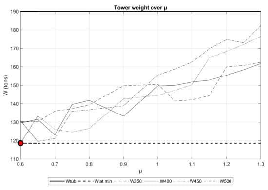
Figure 15.
Total weight of tower cases in correlation with μ and Btop for the 105 m towers.
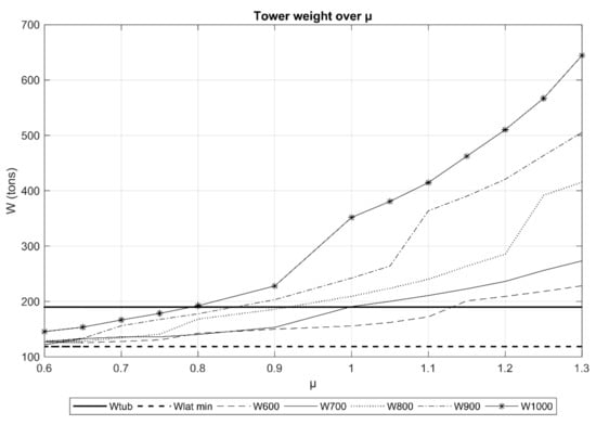
Figure 16.
Total weight of tower cases in correlation with μ and Btop for the 105 m towers.
From Figure 15 it can be concluded that for top widths ranging from 350 to 500 mm, all the tower cases’ weight is lower than the tubular tower weight, independently of μ. In Figure 16 it is evident that for wider top widths, the weight of the tower increases exponentially with the increase of the non-dimensional parameter μ, and especially for μ greater than 1 all the tower weights are greater than the equivalent tubular one, independently of the top tower width. In Figure 17 all towers of equal μ = 0.6 parameter are displayed. The weight of the tower is displayed with regards to the top width for the given number of μ and the weight is symbolized with W and W 0.6 corresponding to the weight of the tower for μ = 0.6.
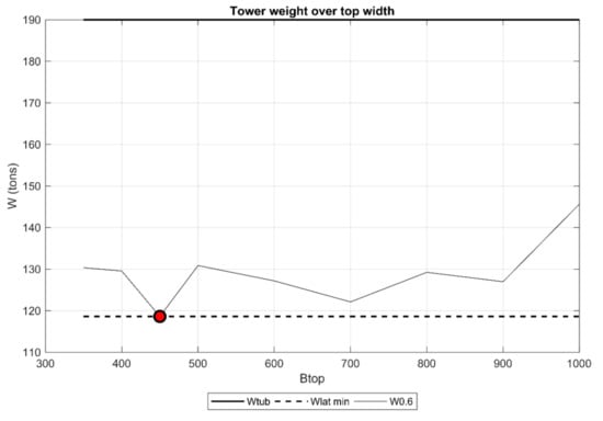
Figure 17.
Weight of tower cases for μ = 0.6 in correlation with Btop for the 105 m towers.
The optimized lattice tower has a weight of 118.62 t (118,623 kg) and is calculated for the model with Btop equal to 450 mm and μ equal to 0.6. The lattice tower that weighs the most has a weight of 644.363 t. As already presented above, the face-bracing trusses are of V shape. The total tower height is split in segments and the driving criterion for the separation of the tower is the angle of the diagonal members of V-braces that in the case presented here is set to 45°. The optimal 105 m tower is split into seven subparts with heights described in Table 3.
Table 3.
Segment heights of 105 m lattice tower.
The lattice tower under investigation has a square base and all four faces consist of the same structural elements since the structure is designed as symmetrical and can be loaded with wind coming from any direction. The cross-sections selected and optimized for the lattice towers of the current work are circular hollow sections and their dimensions for the optimal tower solution are depicted in Table 4.
Table 4.
Cross-section dimensions of 105 m lattice tower.
4. Discussion
The tower constitutes almost one third of the initial construction cost of a wind turbine structure, and therefore suppression of its construction cost results in great economic benefits for the whole project. One aspect that can definitely result in more economical tower construction is the reduction of the total material used. As can be observed from the comparison of the results for the two tower configurations, when discussing the total tower weight of the 76 m tower, the implementation of the lattice solution reduces by almost 40% the total steel used in comparison with the equivalent tubular solution. When examining the 105 m tower, the implementation of the lattice solution also results in a reduction of the material used that is approximately 40%, but when we are constructing a taller structures, the absolute numbers also play a role. In the case of the 76 m tower, the gain is about 50 t while in the 105 m structure it is about 70 t. Taking into account the fact that lattice structures are lightweight structures and require significantly lighter foundations compared to other cantilever solutions, one can definitely say that the lattice solution offers a great opportunity for material reduction as far as steel and concrete are concerned. Last but not least, lattice structures offer great advantages in terms of transportation and in situ construction, since the small-size cross-sections can be transported by conventional trucks and can be mounted on-site with the use of micro-cranes.
5. Conclusions
The work presented here explores the potential substitution of conventional tubular wind turbine towers with lattice ones aiming at the reduction of the total structure weight while maintaining the tower’s load-bearing capacity. Contemporary energy demands, require the construction of taller wind turbines but sustainability strategies require at the same time minimization of the total material used in structures, along with a reduction of the total energy consumption for transportation and mounting. In all these elements, lattice structures appear advantageous compared to tubular ones. Cylindrical shells in general are robust enough, offering higher capacity to the structure, but demand substantially greater amounts of material use. By contrast, lattice structures have been proved to be able to sustain great loads with minimum initial material weight. An additional advantage that lattice structures offer is the lower bending moment transferred to the foundation, which facilitates the concrete foundation design and minimizes its construction cost. In the comparative study carried out in the present work, two wind turbines of 76.15 m height and 105 m height have been designed using both the tubular and the lattice solution. In order to calculate the optimal lattice tower configuration, an iterative procedure has been followed in order to determine the configuration with minimum total tower weight. The design loads are identical between the lattice and the tubular solution and all the optimized towers are well-designed.
When looking into the analyses results in terms of total weight:
- the lattice tower is 40% lighter in both 76 and 105 m towers;
- the total initial construction cost is minimized by almost 15% when adopting the lattice solution.
The advantages that the lattice solution offers in terms of transportation and fabrication, along with the flexibility of its configuration, may lead to great and advantageous changes in the configuration concept in wind turbine tower design. In absolute numbers, the taller the tower, the more the material saved.
Author Contributions
The current work was performed during the project acknowledged below where N.S. performed post-doctoral research under the supervision of the E.K. and C.C.B. The numerical simulations with the aid of Abaqus software were conducted by N.S. The optimization script was mainly developed by the E.K. and implemented in these two types of towers by the N.S. N.S., E.K. and C.C.B. contributed to the final writing and editing of the current manuscript. All authors have read and agreed to the published version of the manuscript.
Funding
This project has received funding from the European Union’s Horizon 2020 research and innovation programme under the Marie Sklodowska-Curie grant agreement number 747921.
Conflicts of Interest
The authors declare no conflict of interest.
References
- IRENA. Future of Wind: Deployment, Investment, Technology, Grid Integration and Socio-Economic Aspects; International Renewable Energy Agency: Abu Dhabi, UAE, 2019. [Google Scholar]
- European Commission. Communication from the Commissionto the European Parliament, the Council, the European Economicand Social Committee and the Committee of the Regions: A Policy Framework for Climate and Energy in the Period from 2020 to2030; European Commission: Brussels, Belgium, 2014. [Google Scholar]
- Wind Europe. Wind Energy in Europe in 2018: Trends and Statistics; Wind Europe: Brussels, Belgium, 2019. [Google Scholar]
- Pineda, I.; Tandieu, P. Wind in Power; Wind Europe: Brussels, Belgium, 2016. [Google Scholar]
- Varun Bhat, I.K.; Prakash, R. LCA of a renewable energy for electricity generation systems—A review. Renew. Sustain. Energ. Rev. 2009, 13, 1067–1073. [Google Scholar] [CrossRef]
- Blanco, M.I. The economics of wind energy. Renew. Sustain. Energ. Rev. 2009, 13, 1372–1382. [Google Scholar] [CrossRef]
- Wind Europe. Wind Energy in Europe in 2019: Trends and Statistics; Wind Europe: Brussels, Belgium, 2020. [Google Scholar]
- Lavassas, I.; Nikolaidis, G.; Zervas, P.; Efthimiou, E.; Doudoumis, I.N.; Baniotopoulos, C.C. Analysis and design of the prototype of a steel 1-MW wind turbine tower. Eng. Struct. 2003, 25, 1097–1106. [Google Scholar] [CrossRef]
- Timoshenko, S.; Gere, J. Theory of Elastic Stability; Tata McGraw-Hill Education: New York, NY, USA, 1961. [Google Scholar]
- Bazant, Z.; Cedolin, L. Stability of Structures: Elastic, Inelastic, Fracture and Damage Theories; World Scientific Publishing: Singapore, 2010. [Google Scholar]
- Teng, J.; Rotter, J. Buckling of Thin Metal Shells; Taylor and Francis: London, UK, 2004. [Google Scholar]
- Baniotopoulos, C.C.; Borri, C.; Stathopoulos, T. Environmental Wind Engineering and Design of Wind Energy Structures; Springer: Vienna, Austria, 2010. [Google Scholar]
- Lee, K.; Bang, H. A study on the prediction of lateral buckling load for wind turbine tower structures. Int. J. Eng. Manuf. 2013, 13, 1829–1836. [Google Scholar] [CrossRef]
- Dimopoulos, C.; Gantes, C. Experimental investigation of buckling of wind turbine tower cylindrical shells with opening and stiffening under bending. Thin Walled Struct. 2012, 54, 140–155. [Google Scholar] [CrossRef]
- Dimopoulos, C.; Gantes, C. Comparison of stiffening types of the cutout in tubular wind turbine towers. J. Construct. Steel Res. 2013, 83, 62–74. [Google Scholar] [CrossRef]
- Rebelo, C.; Veljkovic, M.; Simoes da Silva, L.; Simoes, R.; Henriques, J. Structural monitoring of a wind turbine steel tower—Part I: System description and calibration. Wind Struct. 2012, 12, 285–299. [Google Scholar] [CrossRef]
- Rebelo, C.; Veljkovic, M.; Simoes da Silva, L.; Simoes, R.; Henriques, J. Structural monitoring of a wind turbine steel tower—Part II: Monitoring results. Wind Struct. 2012, 12, 301–311. [Google Scholar] [CrossRef]
- Stavridou, N.; Efthymiou, E.; Gerasimidis, S.; Baniotopoulos, C.C. Investigation of stiffening scheme effectiveness towards buckling stability enhancement in tubular steel wind turbine towers. Steel Comp. Struct. 2015, 19, 1115–1144. [Google Scholar] [CrossRef]
- Stavridou, N.; Efthymiou, E.; Gerasimidis, S.; Baniotopoulos, C.C. Modelling of the structural response of wind energy towers stiffened by internal rings. In Proceedings of the 10th HSTAM International Congress on Mechanics, Chania, Greece, 25–27 May 2013; Technical University of Crete Publishing House: Chania, Greece, 2013; p. 190. [Google Scholar]
- Carril, C.F., Jr.; Isyumov, N.; Brasil, R.M. Experimental study of the wind forces on rectangular latticed communication towers with antennas. J. Wind Eng. Ind. Aerodyn. 2003, 91, 1007–1022. [Google Scholar] [CrossRef]
- Harikrishna, P.; Sanmugasundaram, J.; Gomathinayagam, S.; Lakshmanan, N. Analytical and experimental studies on the gust response of a 52 m tall steel lattice tower under wind loading. Comp. Struct. 1999, 70, 149–160. [Google Scholar] [CrossRef]
- Holmes, J.D. Along-wind response of lattice towers: Part I–derivation of expressions for gust response factors. Eng. Struct. 1994, 16, 287–292. [Google Scholar] [CrossRef]
- Holmes, J.D. Along-wind response of lattice towers: Part II–Aerodynamic damping and deflections. Eng. Struct. 1996, 18, 483–488. [Google Scholar] [CrossRef]
- Holmes, J.D. Along-wind response of lattice towers: Part III–Effective load distributions. Eng. Struct. 1996, 18, 489–494. [Google Scholar] [CrossRef]
- Khedr, M.A.H. Seismic Analysis of Lattice Towers. Ph.D. Thesis, McGill University, Montreal, QC, Canada, 1998. [Google Scholar]
- Khedr, M.A.H.; McClure, G. A simplified method for seismic analysis of lattice telecommunication towers. Can. J. Civ. Eng. 2000, 27, 533–542. [Google Scholar] [CrossRef]
- Madugula, M.K. Dynamic Response of Lattice Towers and Guyed Masts; American Society of Civil Engineers: Reston, VA, USA, 2001. [Google Scholar]
- Gencturk, B.; Attar, A.; Tort, C. Optimal design of lattice wind turbine towers. In Proceedings of the 15th World Conference on Earthquake Engineering, Lisbon, Portugal, 24–28 September 2012; Sociedade Portuguesa de Engenharia Sísmica: Lisbon, Portugal, 2012; pp. 24–28. [Google Scholar]
- Long, H.; Moe, G. Preliminary design of bottom-fixed lattice offshore wind turbine towers in the fatigue limit state by the frequency domain method. J. Offshore Mech. Arct. Eng. 2012, 134, 031902. [Google Scholar] [CrossRef]
- Long, H.; Moe, G.; Fischer, T. Lattice towers for bottom-fixed offshore wind turbines in the ultimate limit state: Variation of some geometric parameters. J. Offshore Mech. Arct. Eng. 2012, 134, 021202. [Google Scholar] [CrossRef]
- Zwick, D.; Muskulus, M.; Moe, G. Iterative optimization approach for the design of full-height lattice towers for offshore wind turbines. Energy Procedia 2012, 24, 297–304. [Google Scholar] [CrossRef]
- Hibbitt, Karlsson and Sorensen Inc. ABAQUS/Standard User’s Manual and ABAQUS CAE Manual, Version 6.12; Hibbitt, Karlsson and Sorensen Inc., ABAQUS: Pawtucket, RI, USA, 2014. [Google Scholar]
- Wolfram, S. The Mathematica; Cambridge University Press: Cambridge, UK, 1999. [Google Scholar]
- Veljkovic, M.; Heistermann, C.; Husson, W.; Limam, M.; Feldmann, M.; Naumes, J.; Pak, D.; Faber, T.; Klose, M.; Fruhner, K.U.; et al. High-Strength Tower in Steel for Wind Turbines (HISTWIN); European Commission Joint Research Center: Ispra, Italy, 2012. [Google Scholar]
- Koiter, W.T. On the Stability of Elastic Equilibrium. Ph.D. Thesis, Delft University, Delft, The Netherlands, 1945. [Google Scholar]
- Speicher, G.; Saal, H. Numerical calculation of limit loads for shells of revolution with particular regard to the applying equivalent initial imperfection. In Buckling of Shell Structures, on Land, in the Sea, and in the Air; Taylor and Francis Group: London, UK, 1991; pp. 466–475. [Google Scholar]
- European Commission. EN 1993-1-6: Eurocode 3: Design of Steel Structures. Part 1-6: Strength and Stability of Shell Structures; European Commission: Brussels, Belgium, 2007. [Google Scholar]
- European Commission. EN 1993-1-1: Eurocode 3: Design of Steel Structures. Part 1-1: General Rules and Rules for Buildings; European Commission: Brussels, Belgium, 2005. [Google Scholar]


Publisher’s Note: MDPI stays neutral with regard to jurisdictional claims in published maps and institutional affiliations. |
© 2020 by the authors. Licensee MDPI, Basel, Switzerland. This article is an open access article distributed under the terms and conditions of the Creative Commons Attribution (CC BY) license (http://creativecommons.org/licenses/by/4.0/).