1. Introduction
Energy plants, including nuclear power plants, have many piping systems that transport fluids and gases. The integrity of these piping systems has a very important impact on the service life of nuclear power plants. Because nuclear power plants require a high level of safety, damage to their piping systems may cause significant environmental and economic losses.
Piping systems may be seriously damaged due to their excessive relative displacement caused by external forces, such as seismic motions. Such displacement may occur between the structures of the piping systems when seismic isolation systems are installed. As the supports of piping systems are installed in several places, each support has different input seismic motions. For most piping systems, the primary natural frequency, which is the main dynamic characteristic, appears approximately between 1–10 Hz. Consequently, piping systems are likely to suffer from large relative displacements.
As piping systems have complicated structures, including components with various specifications, considerable time and effort are required to assess their seismic performance using the finite element method (FEM). In several studies, component tests are conducted on the vulnerable elements of piping systems. Based on the component test results, the seismic capacity of a piping system was assessed using FEM. Such studies have resulted in damage to the piping system, particularly in its elbow and tee fittings, which are structurally vulnerable elements [
1,
2,
3]. Therefore, to reliably assess the seismic capacity of a piping system using FEM, various conditions must be considered in its component tests.
Since the Fukushima Daiichi nuclear disaster in 2011, studies to reassess and improve the seismic performance of nuclear power plant piping systems have been actively conducted on seamless pipes. In Japan, various experiments on elbow and tee fittings have been performed to examine the margin of seismic design for nuclear power plant piping systems. The elastic–plastic behavior, failure mode, and limit load were also analyzed using FEM [
4,
5]. Experiments have also been carried out to investigate the failure modes of major nuclear power plant piping components under cyclic loading [
6], and to define the failure criteria of piping systems using the shaking table test [
7]. Based on the results of these studies, the existing design methods that use linear analysis and stress-based criteria have been changed to methods that use inelastic analysis and strain-based criteria [
8].
To examine the failure mode and failure criteria for low-cycle fatigue behavior, studies have analyzed the nonlinear behavior of pipe elbows under cyclic loading [
9,
10,
11,
12]. The seismic performance of carbon steel pipes and stainless steel pipes has also been assessed using the shaking table test and finite element analysis based on existing research results to examine the suitability of the seismic design criteria for various materials [
2,
13]. A study was conducted to examine the out-of-plane failure behavior of pipe tees using component tests and finite element analysis [
14]. These studies highlighted the importance of defining the limit state, which is the actual failure of the vulnerable parts of piping systems, to ensure the safety of nuclear power plants [
15,
16].
In South Korea, studies have been conducted to improve the seismic performance of nuclear power plant piping systems and pressure vessels. Strain-based criteria have been developed for cases in which plastic deformation occurs in the major components of nuclear power plant piping systems under large seismic load conditions that exceed the design basis earthquake [
17]. Additionally, studies have been conducted to assess the seismic fragility of nuclear power plant piping systems. Based on the results of the component test and the shaking table test, nonlinear finite element analysis was conducted to present seismic fragility curves [
18,
19,
20]. Studies to examine the failure modes of the vulnerable parts of piping systems and to quantify leakage, which is the actual failure, have also been conducted based on the results of component tests to increase the reliability of seismic fragility analysis. As for the limit state of pipe elbows, the failure strain and the failure deformation angle, which were difficult to measure using conventional sensors, were measured using a non-contact measurement method based on image processing [
21]. For pipe elbows, leakage lines and low-cycle fatigue curves for the moment–deformation angle relationship were presented using an image measurement system [
22]. A study was conducted to examine the effect of the T/D ratio of the thickness (T) of a pipe elbow to its outer diameter (D) on the failure behavior [
23]. The damage index of Park and Ang and that of Banon were used to quantitatively express the limit state of a pipe elbow [
24]. A study was conducted to define the limit state of a pipe elbow using the damage index based on the dissipated energy [
25]. Recently, studies have been conducted to present leakage lines and low-cycle fatigue curves under in-plane cyclic loading conditions of pipe tees [
26,
27].
The results of the previous studies revealed that the actual failure of a piping system is the leakage caused by a through-wall crack and that the structural damage mechanism due to an earthquake is the low-cycle fatigue due to large relative displacement that may cause plastic deformation. Therefore, the damage to a piping system under strong cyclic loading conditions, such as earthquakes, is the leakage caused by a through-wall crack that occurs due to damage accumulation.
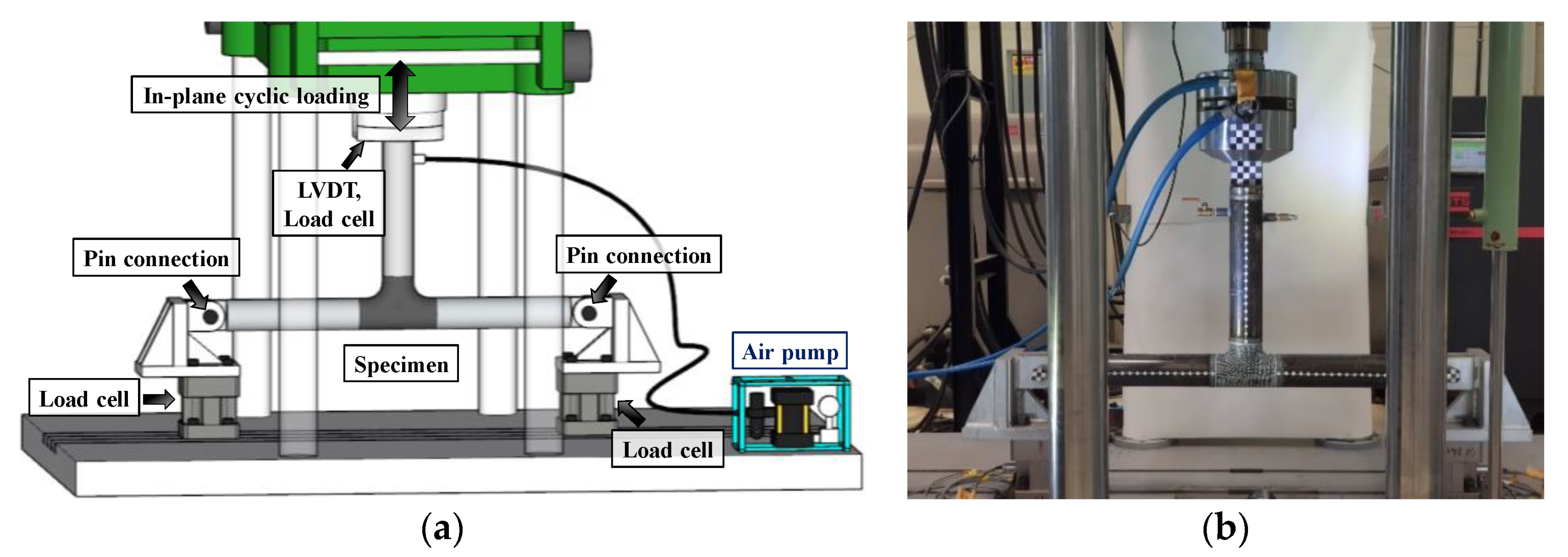
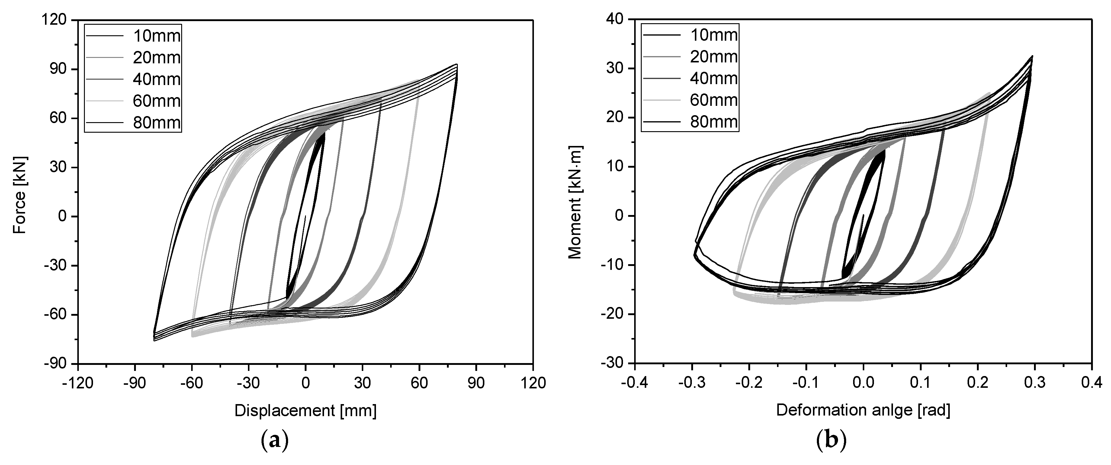
In this study, in-plane cyclic loading tests were conducted via displacement control using test specimens composed of a tee and pipes in the piping system of a nuclear power plant. The tests were conducted using various constant amplitudes until leakage occurred due to a through-wall crack. From the test results, the cumulative dissipated energy based on the force–displacement (P–D) and moment–deformation angle (M–R) relationships were obtained, and the damage index was calculated using the damage indices presented by Park and Ang [
28,
29] and Banon [
30,
31], which can express cumulative damage. To calculate the damage index of Park and Ang and that of Banon, the yield point, which is the limit load, must be defined. Among the various methods of defining the yield point, the tangent intersection (TI) method [
32] defines the point at which the tangent of the elastic slope meets the tangent of the plastic slope in the P–D curve as the limit load. This method is well established in the general P–D relationship and was used to calculate the damage index for pipe elbows [
20,
25]. However, it can be difficult to use if the general slope does not appear in the plastic region. Therefore, in this study, the yield point of a pipe tee, which is its limit load, was defined using the twice-elastic slope (TES) method [
33] presented by the American Society of Mechanical Engineers (ASME) Boiler and the Pressure Vessel Code (Section III, Appendix II). The damage index for the P–D and M–R relationships was calculated using the defined yield point, as well as using the damage index of Park and Ang and that of Banon, and their differences were analyzed.
4. Concluding Remarks
In this study, the failure criteria for an SCH 40 3-inch carbon steel pipe tee in a nuclear power plant piping system were quantified using the damage index based on the force–displacement (P–D) and moment–deformation angle (M–R) relationships.
The failure mode of the SCH 40 3-inch carbon steel pipe tee was defined as the leakage caused by a through-wall crack. In-plane cyclic loading tests were conducted at constant amplitudes until leakage occurred. The loading amplitude varied from ±10 to ±20, ±40, ±60, and ±80 mm in the in-plane cyclic loading tests to consider the elastic–plastic behavior and the SAM. For all the test specimens, leakage caused by a through-wall crack occurred in the upper neutral axis of the tee, and the crack propagated in the neutral axis direction.
To quantitatively define the failure criteria, the damage index of Park and Ang and that of Banon, which can express cumulative damage, were used. For the yield point required to calculate the damage index, the TI method and the TES method were considered. It was found that different yield points can be calculated in the TI method depending on the method of defining the tangent of the slope if the P–D curve is not typical. Therefore, in this study, the TES method presented by the ASME Boiler and Pressure Vessel Code was used to determine the yield point. There may be cases in which the yield point cannot be defined using the TES method. This means that the TES point may not exist owing to the small loading displacement, in which case a method of defining the yield point is required. Therefore, in this study, damage indices were calculated using the yield points obtained from each curve and the yield point (one representative value) obtained from the mean regression curve, and the calculated damage indices were compared. It was confirmed that there was a small difference between the damage indices calculated using the yield points of each curve and the damage index calculated using the yield point of the mean regression curve. Therefore, when the yield point cannot be defined using the TES method because of the small loading amplitude, the representative value of the yield point calculated from the mean regression curve of other experimental results can be used.
At a loading amplitude of ±20 mm or higher, the standard deviation for the average damage index of Park and Ang ranged from 1.64–2.13, and the standard deviation for the average damage index of Banon ranged from 0.12–0.38. In this study, the failure mode of the SCH40 3-inch carbon steel pipe tee was defined as the leakage caused by a through-wall crack. In the limit state, damage indices must be distributed with a small standard deviation from the average value. Therefore, it was reasonable to use the damage index of Banon rather than that of Park and Ang to express the failure criteria for the SCH40 3-inch carbon steel pipe tee.
The damage index of Banon was calculated for all loading amplitudes using the yield point of the mean regression curve. There was a maximum difference of 2.52% between the damage indices of Banon for the P–D and M–R relationships, and all the damage indices were within . The standard deviation for the damage indices calculated using the P–D and M–R relationships was less than 0.6. This indicates that the damage index of Banon is suitable for quantifying the failure criteria for the SCH 40 3-inch carbon steel pipe tee. Therefore, the method of calculating the damage index proposed in this study can be used to calculate the quantitative failure criteria that can express the leakage of nuclear power plant piping systems.


