Article

Modeling PCM Phase Change Temperature and Hysteresis in Ventilation Cooling and Heating Applications

Division of Architectural Engineering, Department of the Built Environment, Aalborg University, Thomas Manns Vej 23, DK-9220 Aalborg Øst, Denmark
*
Author to whom correspondence should be addressed.
Energies 2020, 13(23), 6455; https://doi.org/10.3390/en13236455
Submission received: 22 October 2020 / Revised: 27 November 2020 / Accepted: 1 December 2020 / Published: 6 December 2020
(This article belongs to the Section G: Energy and Buildings)

Abstract

:
Applying phase change material (PCM) for latent heat storage in sustainable building systems has gained increasing attention. However, the nonlinear thermal properties of the material and the hysteresis between the two-phase change processes make the modelling of PCM challenging. Moreover, the influences of the PCM phase transition and hysteresis on the building thermal and energy performance have not been fully understood. This paper reviews the most commonly used modelling methods for PCM from the literature and discusses their advantages and disadvantages. A case study is carried out to examine the accuracy of those models in building simulation tools, including four methods to model the melting and freezing process of a PCM heat exchanger. These results are compared to experimental data of the heat transfer process in a PCM heat exchanger. That showed that the four modelling methods are all accurate for representing the thermal behavior of the PCM heat exchanger. The model with the DSC Cp method with hysteresis performs the best at predicting the heat transfer process in PCM in this case. The impacts of PCM phase change temperature and hysteresis on the building energy-saving potential and thermal comfort are analyzed in another case study, based on one modelling method from the first case study. The building in question is a three-room apartment with PCM-enhanced ventilated windows in Denmark. The study showed that the PCM hysteresis has a larger influence on the building energy consumption than the phase change temperature for both summer night cooling applications and for winter energy storage. However, it does not have a strong impact on the yearly total energy usage. For both summer and winter transition seasons, the PCM hysteresis has a larger influence on the predicted percentage of dissatisfied (PPD) than the phase change temperature, but not a strong impact on the transition season average PPD. It is therefore advised to choose the PCM hysteresis according to whether it is for a summer night cooling or a winter solar energy storage application, as this has a significant impact on the system’s overall efficiency.

1. Introduction

Buildings are intended to protect the occupants from the outdoor weather conditions and provide comfortable environments. Humans are especially sensitive to ambient temperature. They will easily experience thermal discomfort if the indoor temperature is not maintained within a narrow temperature range [1] and without rapid transient change to the operative temperature [2]. Besides, the building sector is the largest energy end-user in the world [3]. Therefore, diminishing indoor space heating and cooling needs have been identified as key targets for the reduction of global energy use and CO2 emissions [4]. Moreover, buildings can modulate their energy profiles to a certain extent by shifting their power load in time. The energy storage capacities of buildings or clusters of buildings can thus be employed to implement demand-side management and building energy flexibility strategies, which can greatly ease the management and improve the stability of smart energy grids with large shares of intermittent renewable energy sources [5].
With regard to the aforementioned matters, phase change materials (PCM) that change their phases near room temperatures (10 °C–30 °C) have drawn considerable attention over the last decade [6]. Unlike materials experiencing only sensible heat storage, a PCM has a phase transition (change in the microstructure of the material) at near ambient temperature. This phase transition requires a considerable amount of thermal energy (latent heat) but occurs with a very limited temperature variation. The latent heat thermal energy storage (LHTES) ability of the PCM is a great asset for high-density thermal storage at a constant temperature in building systems. PCM for building applications has volumetric heat storage capacities which are typically 5 to 14 times greater than sensible heat storage materials such as water or concrete [7].
However, the hysteresis, subcooling and other complex thermal properties of PCM greatly complicate the development of reliable LHTES models for building simulations. It is important to have a better understanding of the hysteresis and subcooling phenomena and the refinement of the numerical model dealing with these issues.
There are mainly two reasons for the hysteresis phenomenon of PCM. One is the improper measurement methods employed to assess PCM properties. There are many well-developed measurement methods for PCM characteristics, including the inverse method, the DSC method and the T-history method. However, every measurement method has its limitations. Noticeable differences in the results can be observed when employing different methods or standards to measure PCM thermal properties [8]. An improper measurement method can lead to the observation of an “apparent hysteresis,” which in most cases, over-estimates the real hysteresis of the material.
The differential scanning calorimetry (DSC) measurement is the standard method to test materials in small samples. It is done by measuring the differences of the heat flows between the reference sample with known thermal properties and the test sample under the same temperature change rate. The measurement results can be very different with different parameter settings. For example, with high heating and cooling heat rates or a large sample size, the inhomogeneity in the material will increase, especially for PCM with low thermal conductivity [8,9]. High heating and cooling heat rates can also increase the subcooling, hysteresis and phase transition temperature range [8,10,11]. However, low heating and cooling rates decrease the magnitude of the DSC signal, which makes it more sensitive to measurement noise [12]. On the other hand, a small sample size could increase the subcooling effect, and may not be representative of some nonhomogeneous materials. Some other more advanced measurement methods, such as the T-history method, are found to be more accurate than DSC for PCM with hysteresis and compound materials [9]. However, those methods are not commercially developed with standard guidance, which makes the comparison among measurements difficult.
Arkar et al. [13,14,15] suggested that the properties of the PCM should be determined using similar heating and cooling rates to the actual temperature change rates of the real application. For PCM in the active building application systems, the thermal response of the PCM is usually 1–8 h for 20 K according to [16], which corresponds to a heating/cooling rate ranging from 0.04 to 0.33 K/min. For passive building applications, the thermal response time could be as long as 12 h, corresponding to a heating/cooling rate of 0.03 K/min.
The other reason for the hysteresis phenomenon of PCM lies in its intrinsic material property. Decreasing the heating and cooling rates, sample size or temperature step can improve the measurement accuracy so that the measurement uncertainty decreases. However, the single enthalpy curve without hysteresis cannot be achieved even with infinitely slow measurement, because the existence of subcooling, incomplete crystallization or polymorphic crystal structures results in different shapes of heating and cooling curves [17]. In certain cases, even with the most accurate measurement method and with the smallest heating/cooling rates, the hysteresis phenomenon can still be observed.
The large enthusiasm of the scientific community for PCM applications during the last few decades has led to the development of numerous numerical models for simulating the thermodynamics and heat storage in LHTES systems. The most commonly used methods to simulate the latent heat are the fixed grid methods [18], which solve phase change problems by accounting for the latent heat of the PCM into the governing energy equation. The latent heat of PCM is defined by either a function of heat capacity, a heat source or a function of enthalpy. Compared with the deformed grid method and the hybrid fixed/deformed method, which can also be used to solve a phase transition problem [19], the space grid is fixed throughout the whole calculation. It is thus simpler to implement the existing heat transfer numerical models and software. They include the heat capacity method and the enthalpy method. The heat capacity method can be further sorted as the square heat capacity method, the triangular heat capacity method or the DSC heat capacity method. However, the accuracy and reliability of PCM numerical models used for building applications are yet to be examined for proper design and simulation purposes [20].
Moreover, an increasing number of researchers are starting to realize the importance of modelling PCM hysteresis for building simulations. Dolado et al. [21] found the existence of temperature hysteresis while studying the thermal performance of a PCM heat exchanger and addressed the necessity of taking it into account in the numerical work. Kuznik et al. [13] applied a single melting/freezing curve of specific heat to their PCM wallboard model and compared it to the experimental data. They figured out that neither of the two methods can predict the temperature profile in the PCM wallboard. They thus suggested the importance of modelling PCM hysteresis in building simulations. Similarly, Barz et al. [22] compared a non-hysteresis model and a hysteresis model to the experimental data of the latent heat storage. The results show that the non-hysteresis model is of poor accuracy to represent the melting/solidification of the PCM storage.
However, the sensitivity analyses of the PCM hysteresis are mostly about the PCM heat transfer process. The influences of the PCM phase transition and hysteresis on buildings’ thermal and energy performance have not been fully studied yet. There have only been a few studies about the sensitivity analysis of the PCM hysteresis on the energy performances of buildings, and those studies drew different conclusions. Ramprasad et al. [23] studied the hysteresis of the PCM on the building envelope and found out that hysteresis does not have a large influence on the annual building energy, but the influences on the surface temperature and zone temperature are considerable. Oppositely to Ramprasad et al., Moreles et al. [24] studied a building with PCM wall and found that an increase of PCM hysteresis temperature within the thermal comfort temperature can greatly decrease the building air-conditioning energy consumption. The discrepancy between the former studies about the influence of PCM hysteresis on the building energy indicates that more detailed and comprehensive studies have to be carried out.
This article aims to examine the current PCM modelling methods and compare them against the experimental data of a PCM heat exchanger, and further study the influences of the PCM thermal properties on both building energy-saving potential and thermal comfort based on the PCM application in a ventilation system, including both a summer application and a winter application. Firstly, the paper reviews the most commonly used modelling methods for the nonlinear thermal properties of the PCM. To test their accuracy, a comparison is made with experimental data of a case study of a PCM heat exchanger with four modelling methods: the square heat capacity method, the triangular heat capacity method, the enthalpy method and the DSC heat capacity method. Finally, one modelling method is selected for another case study of an apartment with PCM-enhanced ventilated windows. The impacts of PCM phase change temperature and hysteresis on building energy-saving potential and thermal comfort are assessed.

2. PCM Modelling Methods in Building Simulations

The challenge of modelling PCM in building simulations lies in dealing with nonlinear thermal properties of the PCM and temperature hysteresis. This section summarizes and compares some of the modelling methods. Section 2.1 introduces the different PCM modelling methods regarding the latent heat of PCM; Section 2.2 discusses the modelling methods of PCM hysteresis; Section 2.3 compares different modelling methods against experimental data.

2.1. PCM Latent Heat Modeling Methods

The most commonly used methods for PCM latent heat modelling are fixed grid methods, including the heat capacity method and the enthalpy method. The heat capacity method can be further sorted into the square heat capacity method, the triangular heat capacity method and the DSC heat capacity method.
The square heat capacity curve method is easy to implement numerically. It is, therefore, the most commonly used method in numerical simulation tools and research studies. Besides, it is fast to compute, which is beneficial for certain applications where the calculation speed is important. Moreover, for many building material manufacturers, only some key parameters of the PCM properties are provided because of the lack of standards. The key parameters are normally the melting/freezing temperature range, melting/freezing temperature peak, specific heat capacity without phase change and total latent heat. A simple heat capacity curve can be easily deducted from those key parameters. The basic equations used for shape-stable PCM in building simulations are the Navier–Stokes momentum equation, the continuity equation and the energy equation, as shown in Equations (1)–(3).
ρ u t + ρ ( u ) u = p + μ 2 u + ρ g β Δ T
u = 0
ρ C p ( T ) ( T t + u T ) = ( λ T )
where ρ is the density of the material (kg/m3); u is the velocity (m/s); t is the time (s); µ is the dynamic viscosity (Pa∙s); β is the thermal expansion coefficient (1/K); T is the temperature of the domain (°C); λ is the thermal conductivity (W/m∙K).
With this limited data provided by the manufacturers, the heat capacity can be calculated with a simple piece-wise square function, as shown in Equation (4) [25].
C p ( T ) = { C s , T < T s C s + C l 2 + L T l T s , T s T T l C l , T > T l
where Cl is the specific heat capacity of PCM in liquid phase (J/kg∙K); Cs is the specific heat capacity of PCM in solid phase (J/kg∙K); L is the latent heat (J/kg); Tl is the PCM melting temperature (°C); Ts is the PCM freezing temperature (°C).
The limitation of this method is that when using it to solve Equation (3), the solver may not converge if the time step is too large or the phase change range is too small. There is a risk of missing the phase transition if the time step is too large and the temperature range of phase change is skipped, which is usually called a step-jump [26,27].
A solution to this problem is to use an approximated approach to redefine the heat capacity by a triangular function from [28,29]. Equations (5) and (6) show the corresponding equations for this triangular heat capacity curve. Alvaro et al. [30] have built a numerical model for the PCM ventilation system which considered hysteresis. The simplified equivalent heat capacity (heat capacity curve has a triangle shape centered on phase transition temperature) is used as the input of the model. The results show that the model is in good agreement with experimental data.
C p ( T ) = { C s , T < T s   and   T > T l C s + M + 2 M T l T s ( T T s + T l 2 ) , T s T T s + T l 2 C s + M 2 M T l T s ( T T s + T l 2 ) , T s + T l 2 T T l
where M is the melting peak factor (J/kg∙K)), which can be calculated with the equation below:
M = 2 L ( T l T s )
The DSC heat capacity method uses the heat capacity curve determined by DSC method as the material input of the model. Hu et al. [31] used this model to simulate a PCM heat exchanger. The model results are in good agreement with the experimental data. Another model used the same approach to simulate the wallboard [13]. The DSC heating and cooling rate was set to 0.05 K/min to approach the real heat exchange rate of the wallboard exposed to summer conditions. It was found that it is essential to use the correct melting/freezing curves when simulating the heating and freezing processes of the wallboard. Eyres et al. [32] first proposed the enthalpy method to solve the heat flow in bodies under non-steady state conditions. The idea is to consider enthalpy as a function of phase fraction and temperature. It was then adopted by [25,33,34,35,36,37]. The Navier–Stokes equation and the continuity equation are the same as Equations (1) and (2). Equations (7)–(9) show the energy equations.
ρ H t = ( λ T )
H = { C p T , T < T s C p T + L ( T T s ) T l T s , T s T T l C p T + L , T > T l
H ( T ) = T r e f T C p ( T ) d T
where Tref is the reference temperature (°C); H is the enthalpy of the PCM (J/kg).
The enthalpy method has been applied in the work of Takeda et al. [38]. The enthalpy curves for melting and freezing processes were measured with the DSC method at 1 °C/min heating and cooling rate. Then an enthalpy function was made by taking a middle path between the melting enthalpy curve and the freezing enthalpy curve. The results from the model reveal similar variations as in the experiment.

2.2. Modeling of PCM Hysteresis

Some researchers try to model the transition between freezing and melting processes within the phase change range. There are mainly two approaches currently. Bony et al. [39] proposed one approach in which the enthalpy transition line between the melting and freezing processes is a straight line that parallels to the sensible enthalpy curve, as shown in Figure 1a. Another approach is used in the models of Kaushik et al. [40]. It suggests that there is no hysteresis shown until the PCM completely solidifies or melts. Then the enthalpy curve changes to another one, as seen in Figure 1b. Ramprasad et al. [23] compared the two approaches with EnergyPlus simulations, and found out that hysteresis does not have a large influence on the annual building energy use, but the influence on the surface temperature and zone temperature is considerable.
Some more complex models are also available for modelling PCM hysteresis, including the static hysteresis model [41], which directly implements data from DSC measurements; and the kinetic model [42,43], in which the melting and freezing are considered as intrinsic dynamic variables as functions of temperature and time, and the parameters are generated by fitting the macro kinetic models to experimental data [22]. Barz et al. [22] compared the aforementioned models by using them for latent heat storage and comparing them to the experimental data. The results show that the static hysteresis model has similar accuracy to the kinetic model, and is easier to implement by direct parametrization from DSC measurements. That method has been chosen for modelling hysteresis in this paper.

2.3. Comparison of the Different PCM Modelling Methods

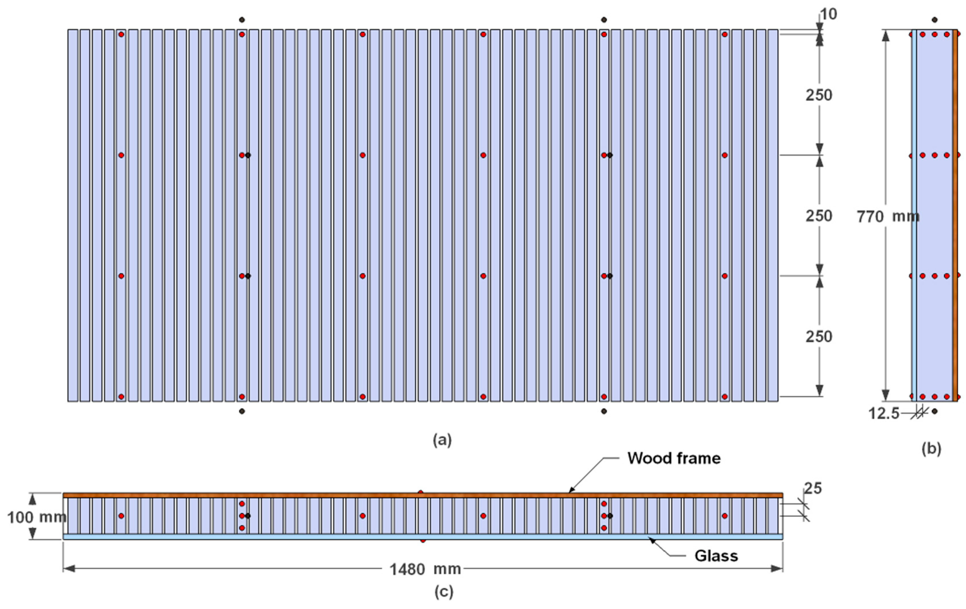
This section analyzes and compares the aforementioned most commonly used PCM modelling methods in the building simulation tools. The comparison study case is an air–PCM heat exchanger made by shape steady PCM plates. The PCM is encapsulated by the fiber board; thus, the convection in the liquid PCM is not simulated. In this case, the finite element numerical model for a PCM heat exchanger is based on the conjunction of heat transfer and laminar flow physics. The heat exchanger consists of 12.5 mm PCM plates spaced by 6 mm air gaps. The test scenario includes a night ventilation mode and a ventilation pre-cooling mode. In night ventilation mode, the low-temperature ambient air is supplied into the heat exchanger to discharge the PCM during nighttime. In ventilation pre-cooling mode, the PCM is used to cool down the high-temperature ambient air ventilated through the heat exchanger during the daytime when cooling is needed. The influences of the PCM modelling methods on the model’s accuracy are evaluated based on comparisons with experimental data. The PCM in the system is paraffin wax 22. Its properties are listed in Table 1. The hysteresis of the PCM is around 1 °C according to the DSC test with a heating/cooling rate of 0.5 °C/min. The experiment is set up in a climate chamber with a hot zone and a cold zone, which are both conditioned by a heater and cooler. The air temperature in the hot zone is 29 ± 1 °C, and the air temperature in the cold zone is 9 ± 1 °C. During the night ventilation mode, the cold air in the cold zone is directed to the PCM heat exchanger bottom inlet. After the PCM is totally cooled down (solidified), the hot air in from the hot zone is directed into the PCM heat exchanger top inlet. The PCM temperatures is monitored at four different heights inside the heat exchanger, as shown in Figure 2. More details about the model and experimental case can be found in [31].
Figure 3 shows the average PCM temperature profiles at a height of 510 mm in the heat exchanger predicted by different PCM models and measured during the experiments. The temperature profiles of all the models show trends that are similar to the experimental data. The curve of the DSC heat capacity method with a 1 °C temperature hysteresis has the best fit to the experiment, especially during the phase transition periods (0.7–2.4 h and 6.7–10 h).
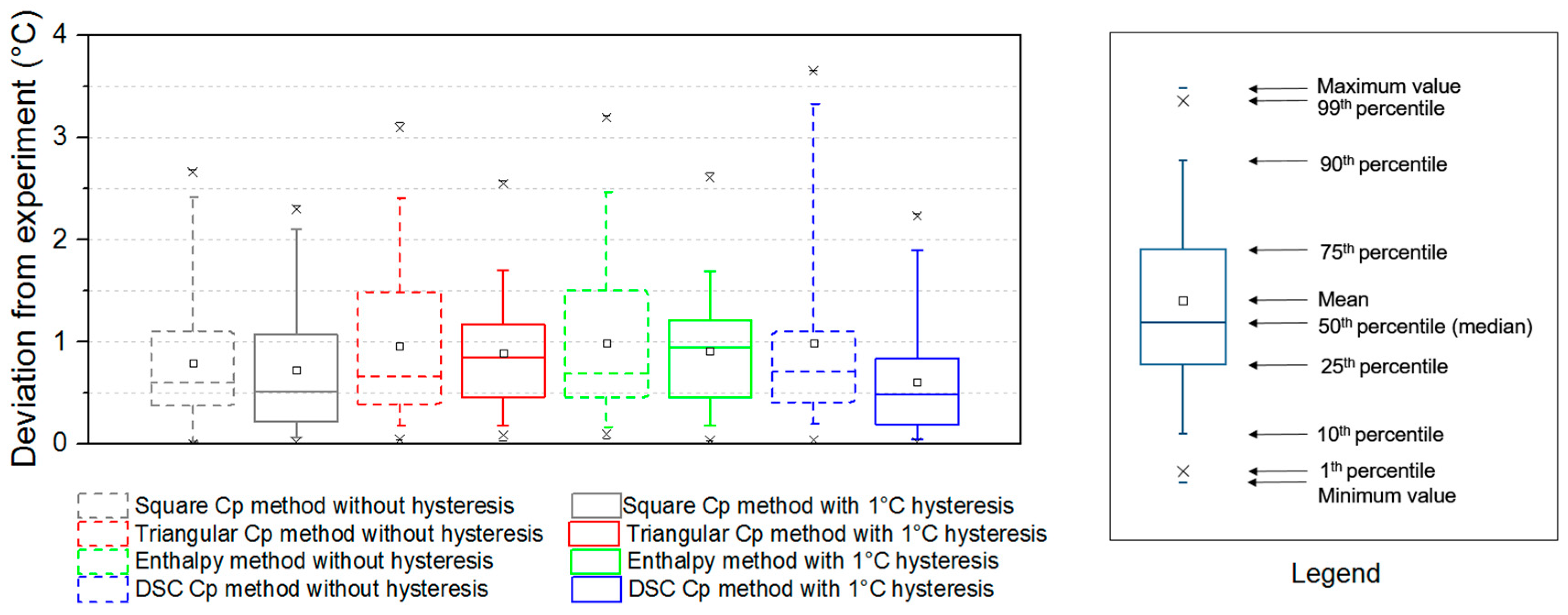
Figure 4 shows the temperature deviation between model results and experimental data. The minimum model deviation comes from the DSC heat capacity method with a 1 °C temperature hysteresis. All the models show acceptable accuracy. The model deviations are always less than 1 °C. The model with the DSC heat capacity method and 1 °C temperature hysteresis has the lowest deviation from the experiment, with 0.6 °C of average deviation and 2.2 °C of maximum deviation.

3. The Effect of Phase Transition Temperature and Hysteresis Degree on the Building Energy

This section looks into the influences of the PCM phase transition temperature and hysteresis degree on the building’s energy performance. The investigated model is the DSC heat capacity method with hysteresis, as it gives the best fit to experimental data (see Section 2). PCM for summer applications and winter applications are studied separately with two different Energyplus models. The PCM is modelled with a 1D heat conduction finite difference model in Energyplus, which calculates the average PCM temperature of the whole PCM in the PCM-enhanced ventilated windows (PCMVW).
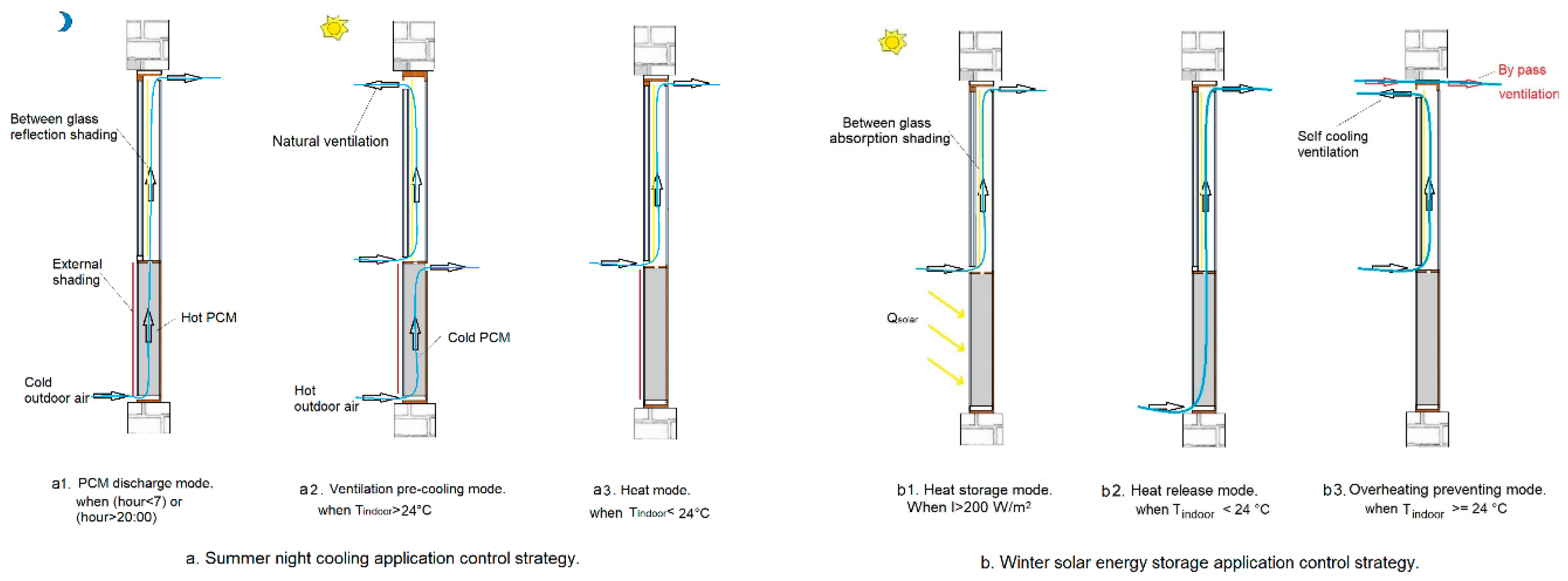
Two PCMVWs are installed in the external walls of the southwest room of a three-room apartment in Denmark. The PCMVW is equipped with the PCM heat exchanger presented in Section 2.3 with a ventilated window mounted on a top of it. The operating control strategy of the PCMVW is explained in Figure 5. For the summer night cooling applications, the PCM thermal energy storage is discharged by the cold outdoor air at nighttime. It then pre-cools the supplied fresh air during day time (Figure 5a1). The PCM thermal energy storage is fully shaded from solar radiation, while the ventilated window is shaded by external shading when the indoor air temperature is higher than 24 °C (Figure 5a2). The airflow rate through the PCMVW is based on the people load of the room, which is 60 m3/h/person in summer and 30 m3/h/person in winter, according to the optimization results of the airflow rate in [44]. For winter solar energy storage applications, the PCM accumulates solar energy during the day (Figure 5b1), and later releases the it to preheat the inlet fresh air (Figure 5b2). There is no shading for the PCM thermal energy storage and the ventilated window. The airflow rate is the same as for the summer night cooling applications. The details of the PCMVW model and model validation can be found in [45].
This study is conducted for the Danish climate. The summer application operated from 1st May to 31st October, while the winter application operated from 1st November to 30th April. The heating, ventilation and air conditioning (HVAC) system only operated during severe summer and severe winter periods, in cases when the PCM thermal energy storage could not provide enough pre-heated or pre-cooled air. The HVAC system is a packaged terminal heat pump system with a heating coil COP of 2.87 and cooling coil COP of 1.87. The room air temperature setpoint is 22–26 °C. The period of severe summer is from 1st June to 31st August. The period for severe winter is from 1st November to 29th February. The transition season is when there is no operating HVAC system. The summer transition season is May, September and October, and the winter transition season is March and April. The corresponding PCMVW and HVAC operation schedules can be found in Figure 6.
A local sensitivity analysis is conducted to determine which parameters had significant influences on the system’s energy demand during the severe summer and winter periods. The sensitivity analysis is performed by the methodology of [46,47]:
  • Define input variables with their variation ranges.
  • Set variation level m for each input variable in a discrete distribution.
  • Use a one-parameter-at-a-time (OAT) method to generate p = m×n observations, where n is the number of input variables.
  • Obtain output variables by conducting n simulations.
  • Visualize the output distribution.
Assess the importance of each input parameter to the output by calculating the sensitivity index, which is calculated by the equation below:
S I i = E max , i E min , i E max
where SIi is the local sensitivity index; Emax,i and Emin,i are the maximum and minimum outputs corresponding to the ith input; Emax is the maximum global output among all the inputs of all the variables.
In this case, the input parameters are the phase transition temperature and hysteresis degree, and the outputs are the summer cooling energy demand, winter heating energy demand and total heating + cooling energy demand of the room.
For the transition seasons, the HVAC system is not operating. The PCMVW is supposed to cover the heating and cooling energy demands. The system’s performance is then evaluated with the predicted percentage of dissatisfied (PPD) proposed by Fanger [48]. The lower the PPD, the better the indoor environment quality.
The range of the PCM phase transition temperature in this study is from 15 to 25 °C, and the range of the PCM hysteresis degree is from 0 to 6 °C. The values are chosen because the most commonly used PCM in building applications have hysteresis from 0 to 6 °C, as shown in Appendix A (Table A1), which is a literature review of the PCM in building applications.

3.1. Severe Summer and Winter Conditions

The study starts with the PCM phase change temperature and hysteresis degrees and their influences on the room energy demand for severe summer (1st June–31th August) and winter (1st November–29th February) conditions, when the HVAC is used to guarantee good quality of the indoor environment.
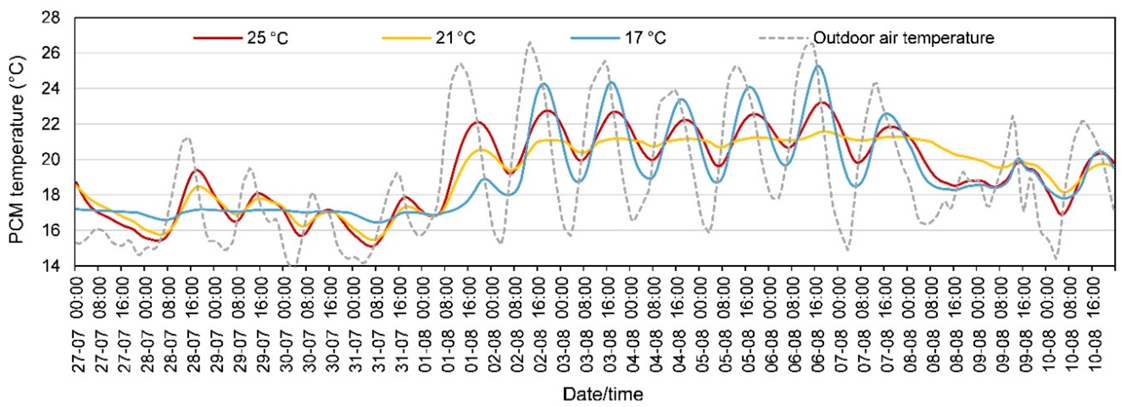
For summer night cooling applications during the severe summer conditions, 11 PCM with different phase transition temperatures (no hysteresis) are firstly studied. For those PCM, the melting temperature equals freezing temperature. Their latent heat, thermal conductivity and other properties are all the same. Figure 7 shows some of the PCM temperatures from those cases. There are large differences in the PCM temperature profiles for PCM with different phase transition temperatures. For the days with low average daily outdoor air temperature, the PCM with low phase transition temperature has a more stable temperature profile and a relatively low temperature during the daytime. For the days with high average daily outdoor air temperature, the PCM with high phase transition temperature has a more stable temperature profile and a relatively low temperature during the daytime. For PCM with a 21 °C phase transition temperature, the PCM temperature is more stable than the PCM with 25 °C for most days. That is because the average outdoor air temperature is much closer to 21 °C, so that the PCM with a 21 °C phase transition temperature is more activated than the one with a 25 °C phase transition temperature. The relations between the PCM phase change temperature and the PCM temperature profiles are quite different from day to day due to the differences in the daily outdoor air temperature.
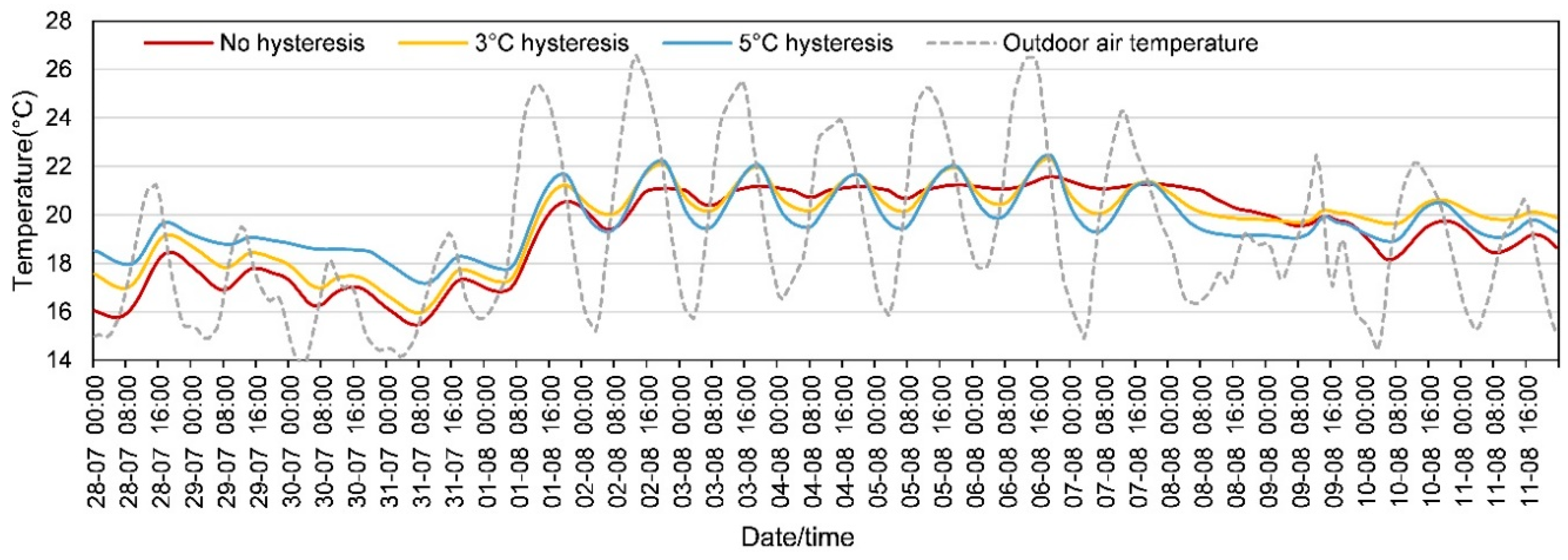
The study is carried out with seven PCM with different hysteresis degrees during severe summer. For those PCM, hysteresis degree is the difference between the melting peak and the freezing peak; melting peak = 21 °C + hysteresis/2; freezing peak = 21 °C − hysteresis/2. Figure 8 shows some of the PCM temperatures. It shows that PCM with no hysteresis has the most stable temperature profile and lowest temperature during the daytime for most of the days when the ventilation pre-cooling is needed, and the PCM with 5 °C hysteresis has the highest temperature during the daytime for most of the days when the ventilation pre-cooling is needed. When outdoor air temperature is relatively low, the PCM with no hysteresis has the lowest temperature during both daytime and nighttime. It indicates that PCM with no hysteresis can benefit the building’s energy-saving the most during severe summer.
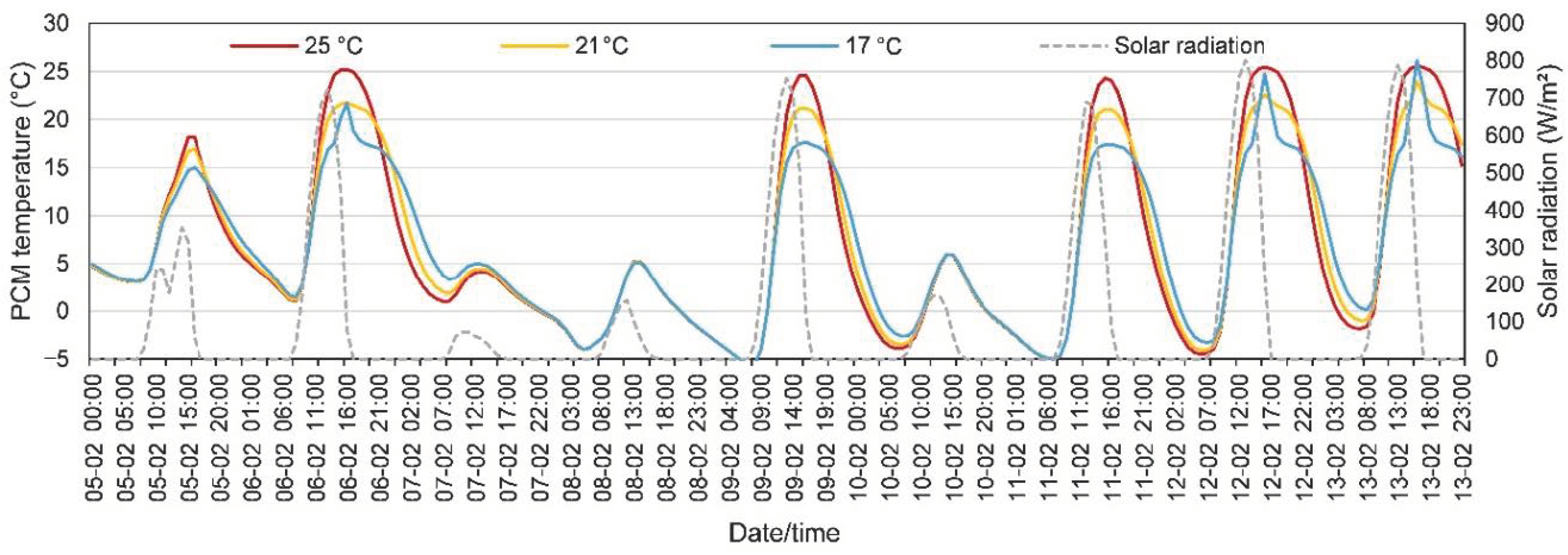
For winter solar energy storage applications during the severe winter condition, the study compares the models using the same 11 PCM with different phase transition temperatures (no hysteresis), and 7 PCM with different hysteresis degrees. Figure 9 shows the influences of the PCM phase change temperature on the PCM temperature profiles. For the days with high solar radiation, the PCM with a higher phase transition temperature has a higher temperature during the day; during the night time (when the ventilation pre-heating is mostly needed), the PCM with a 25 °C transition temperature cools down the fastest. There is no significant difference regarding the PCM temperature when solar radiation is low. In general, it is hard to tell from the PCM temperature profile whether the PCM phase change temperature has a positive or a negative influence on the energy-saving potential.
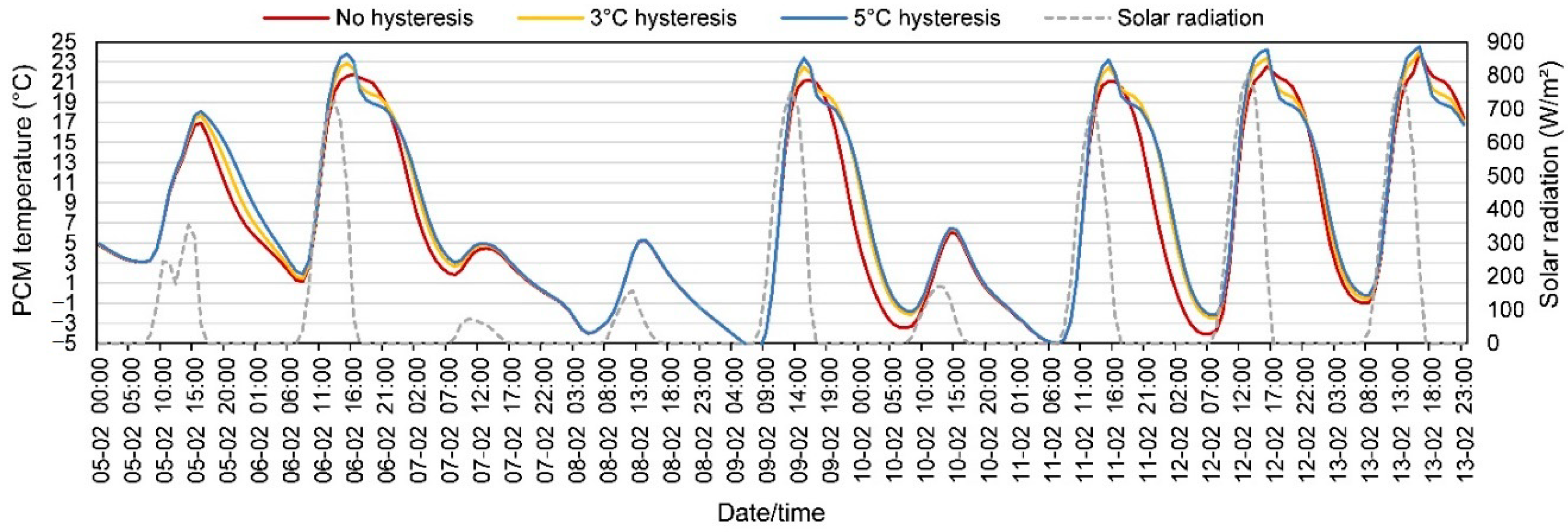
Subsequently, Figure 10 shows the influences of PCM hysteresis degree on the PCM temperature profiles for winter solar energy storage applications. It shows that for the days with high solar radiation, PCM with larger hysteresis has a higher temperature during most of the nighttime when the ventilation pre-heating is needed, for example, 5th and 6th of February. For the days with low solar radiation, no significant difference is found among the models with different hysteresis, as the case of 8th February shows.
The PCM temperature profiles depend on the outdoor weather conditions, e.g., outdoor air temperature for summer and outside surface received solar radiation for winter, which makes it hard to predict the building’s energy performance based on the analysis of several days. Figure 11 summarizes the heat pump’s energy demands for the room with different PCM phase change temperatures during the whole severe summer and winter seasons, and compares them to the model with no PCM and only ventilated window with same ventilation strategy and airflow rate. Figure 11a shows that compared with the model without PCM, the models with PCM which have different phase transition temperatures all have lower energy demands. With the increase of the PCM phase change temperature, the energy demands of the room for both summer and winter tend to increase slightly. Figure 11b indicates that for severe summer, the energy savings increase and then decrease along with the increase of the PCM phase change temperature. For severe winter, the energy savings decrease along with the increase of the PCM phase change temperature. As a result, the total energy savings in severe seasons increase and then decrease along with the increase of the PCM phase change temperature. However, the change is quite small compared to the total energy demand.
The influence of the PCM hysteresis on the room’s energy demand is shown in Figure 12a. It shows that, compared with the model without PCM, the models with PCM and different hysteresis degrees all have lower energy demands for summer, winter and total periods. Along with the increase of the PCM hysteresis, the summer energy demand increases, while the winter energy demand decreases. The decreasing energy demand in winter is higher than the increasing energy demand in summer. As a result, the total heat pump energy demand decreases along with the increase of the PCM hysteresis degree. Figure 12b shows that along with the increase of the PCM hysteresis, the energy savings in summer decrease, while the energy savings in winter increase. The total energy saving in severe seasons increases along with the increase of the hysteresis, due to more energy savings during winter.
The sensitivity analysis determines which variable has a higher impact on the model’s energy demand during severe summer and winter seasons. Figure 13 shows the local sensitivity indexes of the PCM phase change temperature and hysteresis on the building’s energy demand. For both summer and winter, the PCM hysteresis degree has a much bigger sensitivity index than the phase change temperature —0.253 and 0.207, respectively. However, for the yearly total energy demand, both phase transition temperature and hysteresis degree have small sensitivity indexes. That indicates that the PCM hysteresis degree has large influences on the summer and winter energy demands, but not a large influence on the annual total energy demand. The phase change temperature has a high impact on the summer energy demand, but not so high of an impact on the winter energy demand and annual total energy demand.

3.2. Transition Seasons

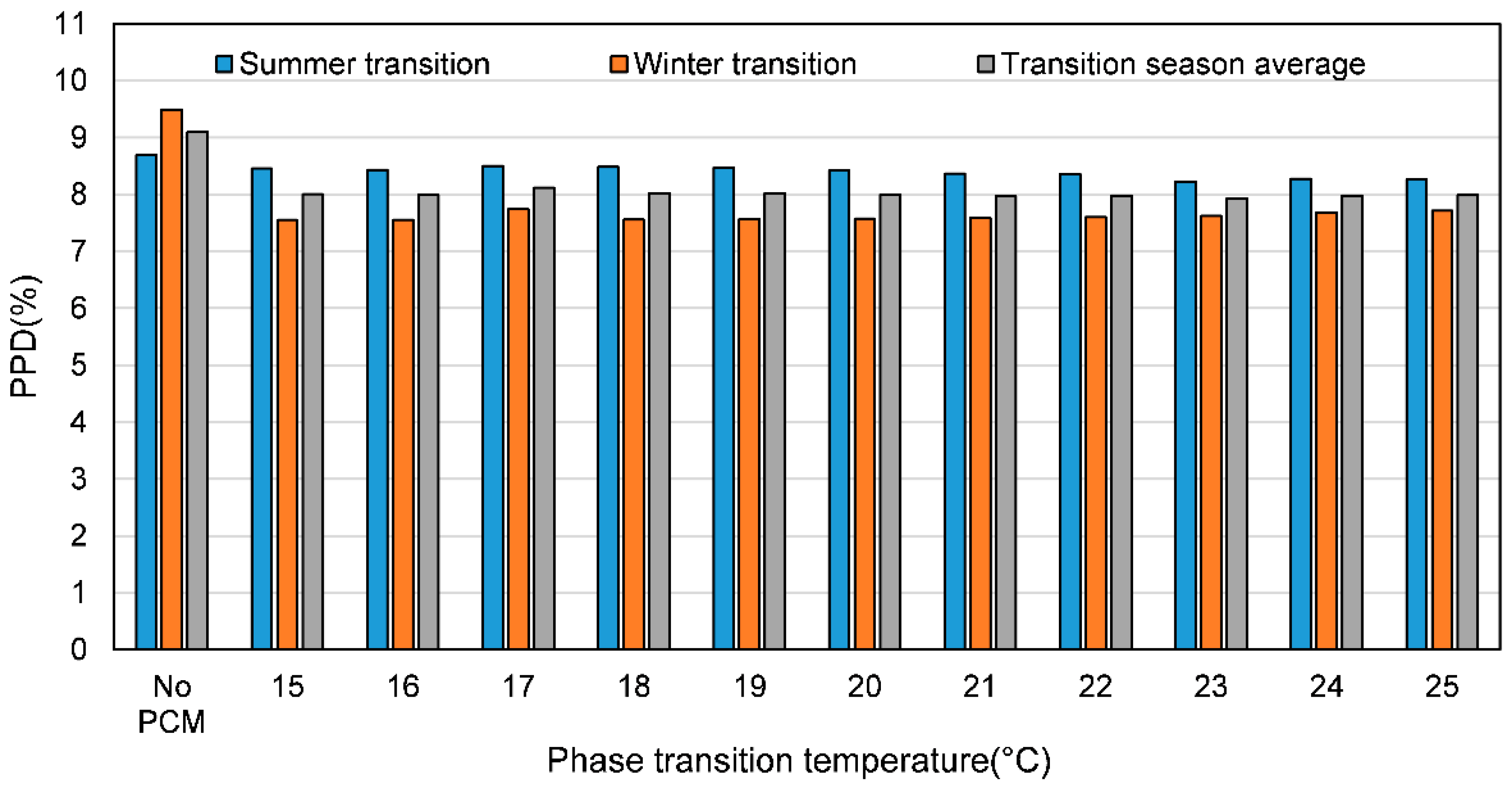
For the transition seasons, the HVAC system does not operate. It is thus the PCMVW that solely regulates the indoor thermal comfort. The PPD is used to examine the thermal comfort of the study cases. The lower the PPD, the better the indoor thermal comfort. Figure 14 shows the influence of the PCM phase change temperature on the PPD during transition seasons. Compared to the model without PCM, the models with PCM all have lower PPD. For the summer transition season, the PPD decreases along with the increase of the phase change temperature. For the winter transition season, the PPD increases along with the increase of the PCM phase change temperature, except for 17 °C. Consequently, the average PPD during the transition season remains the same along with the increase of the PCM phase transition temperature, except for 17 °C, which is slightly higher.
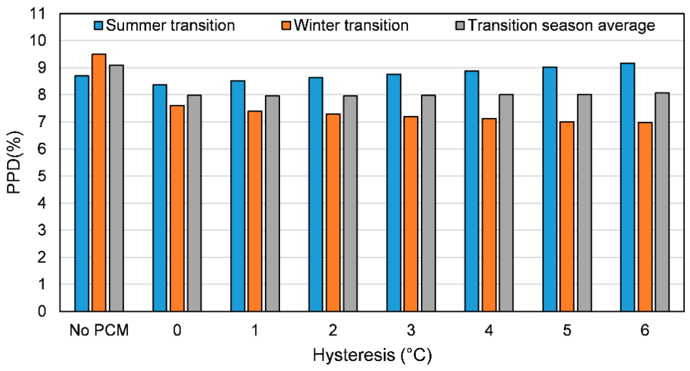
Similarly, the influence of the PCM hysteresis on the PPD is shown in Figure 15. Compared to the model without PCM, the models with PCM all have lower PPD. For the summer transition season, the PPD increases along with the increase of the PCM hysteresis. For the winter transition season, the PPD decreases along with the increase of the PCM hysteresis degree. Consequently, the average PPD during the transition season remains the same along with the increase of the PCM hysteresis degree.
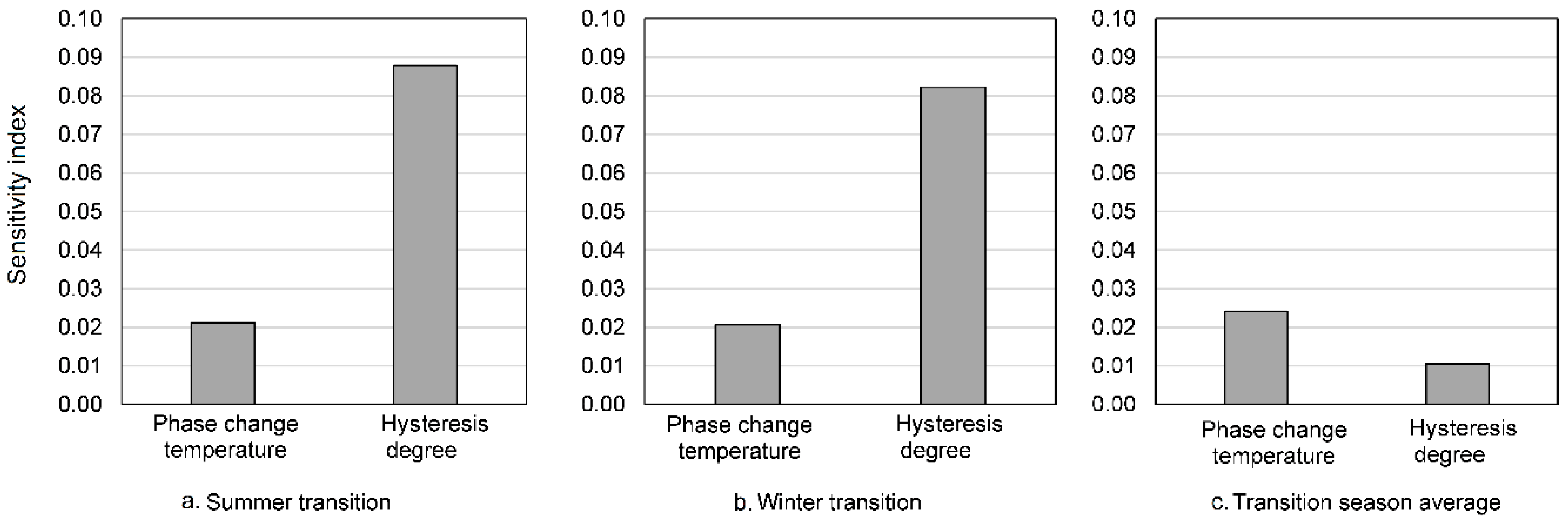
Another sensitivity analysis is conducted to study which parameter has a higher impact on indoor thermal comfort during transition seasons. The results are presented in Figure 16. It is shown that the hysteresis degree has a larger sensitivity index than the phase change temperature for both summer and winter transition seasons—0.088 and 0.082, respectively. However, the transition season average sensitivity indexes of both hysteresis degree and phase transition temperature are not so high, which indicates that the PCM has a large influence on the thermal comfort in summer transition and winter transition seasons, but not a large influence on the annually average thermal comfort during transition seasons. The phase change temperature does not have great influence on the thermal comfort in transition seasons.
In general, the phase change transition temperature and hysteresis have higher impacts on the severe summer and winter seasons than the transition seasons, for both summer and winter applications. The reason could be that for transition seasons, the building needs less regulation and energy input to achieve good thermal comfort.

4. Discussion

The modelling of PCM is more complicated than other building materials due to its nonlinear thermal properties. Moreover, the phase change occurs over a temperature range and presents temperature hysteresis between the melting and the freezing processes, which makes the modelling of PCM challenging. This paper studied the different modelling methods of PCM used in building simulations regarding their accuracies compared to an air–PCM heat exchanger, and the influences of PCM phase change temperature and hysteresis on a building’s energy-saving potential and thermal comfort.
The main reasons for PCM hysteresis identified in the literature are divided into two categories. One is due to the misconception of hysteresis because of improper measurement methods. This apparent hysteresis is avoidable if overall knowledge about the thermal properties of the PCM is obtained before a suitable measurement method is chosen, such as the homogenous and subcooling level of the material, the typical heat rate and the temperature range of the PCM application. The other one is due to the intrinsic material properties because of the existence of subcooling, incomplete crystallization or polymorphic crystal structures.
The most commonly used PCM modelling methods found in the literature are introduced and categorized. A case study of the heating and cooling processes of a PCM heat exchanger is conducted with four selected modelling technics. The conclusion is that the four modelling methods (the square heat capacity method, the triangular heat capacity method, the enthalpy method and the differential scanning calorimetry (DSC) heat capacity method) are equally accurate at representing the thermal behavior of the PCM heat exchanger. The model with the DSC heat capacity method and a 1 °C hysteresis is, however, the most accurate in that case.
A second case study with a southwest room in an apartment with two PCM-enhanced ventilated windows in Denmark is conducted. The PCM is modelled with the DSC heat capacity method and temperature hysteresis. It is shown that the PCM hysteresis has a larger influence on the heat pump energy consumption than the phase change temperature for both summer night cooling and winter energy storage. For summer night cooling, the room energy demand increases along with the increase of the hysteresis. For winter solar energy storage, the room energy demand decreases along with the increase of the hysteresis. As a result, the PCM hysteresis does not have a strong impact on the heat pump’s yearly total energy demand. For both summer and winter transition seasons, the PCM hysteresis has a larger influence on the PPD than the phase change temperature, but not a strong impact on the transition season average PPD.
The findings of this work about the PCM hysteresis’s effect on the building energy are quite the opposite to those of Ramprasad et al. [23]. and Moreles et al. [24]. The reason is that, in this paper, the summer application, winter application and transition season application are studied separately. In contrast, the former studies are only based on one PCM application. Besides the hysteresis, this paper also took PCM phase change temperature into account.
A suggestion for PCM modelling and experimental works is that one should be more considerate when choosing PCM modelling methods. Overall knowledge or some measurement of the PCM properties is necessary from the beginning of the investigations. The adequate modelling methods can be decided on based on the understanding of the material characteristics. Meanwhile, the choice of the PCM should fit the application, because a building’s energy demand changes differently as a function of the PCM hysteresis for summer night cooling and winter solar energy storage. Moreover, the boundary conditions should be carefully defined and chosen based on real building applications, such as the exposed temperature range, the heating/cooling rate and the phase transition range of the chosen PCM. The PCM properties should be characterized for the entire temperature range of the application, as the PCM properties might differ significantly from what one could expect.
Finally, one should keep in mind that this paper presents a study based on the Danish climate, which has a fairly mild summer. Such study should be extended to other climates.

Author Contributions

Conceptualization, Y.H. and P.K.H.; methodology, Y.H.; software, R.G.; validation, Y.H.; data curation, Y.H.; writing—original draft preparation, Y.H., R.G. and H.J.; writing—review and editing, R.G., H.J. and P.K.H.; funding acquisition, P.K.H. All authors have read and agreed to the published version of the manuscript.

Funding

This research was funded by the EU Horizon 2020 research and innovation program (ReCO2ST), grant number 882901.

Conflicts of Interest

The authors declare no conflict of interest.

Appendix A

Table A1. The thermal properties of PCM found in the literature for building applications (the hysteresis degree is calculated as the difference between melting peak and freezing peak).
TypeMelting Range (°C)Freezing Range (°C)Melting Peak (°C)Freezing Peak (°C)Hysteresis Degree (°C)Latent Heat (kJ/kg)Measurement MethodReference
MePCM from PG8H2–E23.9–26.918.4–23.125.5420.215.33-DSC 1 °C/min[49]
Dodecanol23.8–27.118.3–23.225.2220.115.11-DSC 1 °C/min[49]
MePCM from PG8H223.7–27.218.1–22.925.1420.075.07-DSC 1 °C/min[49]
Paraffin23–2920–252327.74.7179DSC 2 °C/min[50]
Paraffin within copolymer15.1–28.29.6–24.522.217.84.4107.5DSC 0.05 °C/min[51]
Paraffin within copolymer10–2812–2922.117.94.272.4/71.0DSC 0.05 °C/min[13]
PCM–wallboard16.8–19.3516.9–22.121.0516.984.0735DSC 0.2 °C/min[52]
Q2016–2413–1820164210–250DSC[53]
Paraffin PCM 60–7−53−0.53.5178DSC 1 °C/min[54]
C2424–2721–2324273140DSC[55]
Q2724–3023–2727243210–250DSC[53]
Q2927–3224–2729263210–250DSC[53]
Paraffin Microtek 37 D32–3729–3536333220DSC 0.15 °C/min[56]
Paraffin hydrocarbon23–28.521–24.925.522.92.675DSC 1 °C/min[38]
Paraffin PCM 2815–2815–222320.52.5161DSC 1 °C/min[54]
Gallium29.5–30.526.9–293027.52.580T-history[9]
Fatty acid wall board18.5–24.215.0–18.620.317.92.439.1DSC 0.2 °C/min[57]
Q2320–2618–2423212210–250DSC[53]
Q2523–2822–2525232210–250DSC[53]
Paraffin in gypsum board25–28.524–27.52826.51.575DSC 2 °C/min[58]
Gypsum–PCM compound21–2420–22.52422.51.5-DSC 0.05 °C/min[59]
C13H28−6.7–(−4.5)−6.3–(−7.9)−5.6−7.11.5210T-history[60]
PCM–plaster compound 24.1–28.523.2–27.128.1226.81.3216.5DSC 1~2 °C/min[61]
Hexadecane16.5–19.516.2–17.21816.71.3236T-history[9]
RT2724.5–28.225.0–26.92725.91.1180T-history[9]
HS22P (inorganic)21–25-23221185T-history[62]
RT27 (organic paraffin)26.86–28.6927.94–26.4428.3727.380.99130.8DSC 1 °C/min[63]
Butyl stearate 16–20.916–20.820.920.40.530.7DSC[64]
Emerest 232616.69–19.7516.51–19.619.5719.450.12140DSC 0.2 °C/min[52]
C21 (salt hydrate)21–2618–2221210134DSC[55]
Paraffin RT 2522–2623–2625250-DSC 0.2 °C/min[15]

References

  1. International Organization for Standardization. ISO 7730: 2005, Ergonomics of the Thermal Environment–Analytical Determination and Interpretation of Thermal Comfort Using Calculation of the PMV and PPD Indices and Local Thermal Comfort Criteria; Geneva, Switzerland, 2005; Available online: https://www.iso.org/standard/39155.html (accessed on 4 November 2020).
  2. American Society of Heating, Refrigerating and Air-conditioning Engineers. ANSI/ASHRAE Standard 55: Thermal Environmental Conditions for Human Occupancy; American Society of Heating, Refrigerating and Air-conditioning Engineers: Atlanta, GA, USA, 2004. [Google Scholar]
  3. International Energy Agency. Transition to Sustainable Buildings: Strategies and Opportunities to 2050; OECD/IEA: Paris, French, 2013; Available online: https://www.oecd-ilibrary.org/energy/transition-to-sustainable-buildings_9789264202955-en (accessed on 4 November 2020).
  4. The European Parliament and the Council of the European Union. Directive 2010/31/EU of the European Parliament and of the Council of 19 May 2010 on the Energy Performance of Buildings. OJEU 2010, 153, 13–35. Available online: https://eur-lex.europa.eu/LexUriServ/LexUriServ.do?uri=OJ%3AL%3A2010%3A153%3A0013%3A0035%3AEN%3APDF (accessed on 4 November 2020).
  5. Jensen, S.Ø.; Marszal-Pomianowska, A.; Lollini, R.; Pasut, W.; Knotzer, A.; Engelmann, P.; Stafford, A.; Reynders, G. IEA EBC Annex 67 Energy Flexible Buildings. Energy Build. 2017, 155, 25–34. [Google Scholar] [CrossRef] [Green Version]
  6. Pomianowski, M.; Heiselberg, P.; Zhang, Y. Review of thermal energy storage technologies based on PCM application in buildings. Energy Build. 2013, 67, 56–69. [Google Scholar] [CrossRef]
  7. Sharma, A.; Tyagi, V.V.; Chen, C.R.; Buddhi, D. Review on thermal energy storage with phase change materials and applications. Renew. Sustain. Energy Rev. 2009, 13, 318–345. [Google Scholar] [CrossRef]
  8. Gschwander, S.; Lazaro, A.; Cabeza, L.F.; Günther, E.; Fois, M.; Chui, J. Development of a Test Standard for PCM and TCM Characterization, Part 1: Characterization of Phase Change Materials Compact Thermal Energy Storage. Technical Report for the IEA Solar Heating and Cooling/ Energy Conservation through Energy Storage programme–Task 42/ Annex 24: 2011. Available online: http://task42.iea-shc.org/Data/Sites/1/publications/Task4224-A2-1-Characterization-of-Phase-Change-Materials.pdf (accessed on 4 November 2020).
  9. Lázaro, A.; Günther, E.; Mehling, H.; Hiebler, S.; Marín, J.M.; Zalba, B. Verification of a T-history installation to measure enthalpy versus temperature curves of phase change materials. Meas. Sci. Technol. 2006, 17, 2168–2174. [Google Scholar] [CrossRef]
  10. Diaconu, B.M.; Varga, S.; Oliveira, A.C. Experimental assessment of heat storage properties and heat transfer characteristics of a phase change material slurry for air conditioning applications. Appl. Energy 2010, 87, 620–628. [Google Scholar] [CrossRef]
  11. He, B.; Martin, V.; Setterwall, F. Phase transition temperature ranges and storage density of paraffin wax phase change materials. Energy 2004, 29, 1785–1804. [Google Scholar] [CrossRef]
  12. Hu, Y. PCM Enhanced Ventilated Window-Configuration and Control Strategy Development. Ph.D. Thesis, Aalborg Universitetsforlag, Aalborg, Denmark, 2020. [Google Scholar]
  13. Kuznik, F.; Virgone, J. Experimental investigation of wallboard containing phase change material: Data for validation of numerical modeling. Energy Build. 2009, 41, 561–570. [Google Scholar] [CrossRef]
  14. Arkar, C.; Medved, S. Influence of accuracy of thermal property data of a phase change material on the result of a numerical model of a packed bed latent heat storage with spheres. Thermochim. Acta 2005, 438, 192–201. [Google Scholar] [CrossRef]
  15. Iten, M.; Liu, S.; Shukla, A.; Silva, P.D. Investigating the impact of Cp-T values determined by DSC on the PCM-CFD model. Appl. Therm. Eng. 2017, 117, 65–75. [Google Scholar] [CrossRef]
  16. Hu, Y.; Heiselberg, P.; Johra, H.; Guo, R. Experimental and numerical study of a PCM solar air heat exchanger and its ventilation preheating effectiveness. Renew. Energy 2019, 145, 106–115. [Google Scholar] [CrossRef]
  17. Rathgeber, C.; Schmit, H.; Hennemann, P.; Hiebler, S. Calibration of a T-History calorimeter to measure enthalpy curves of phase change materials in the temperature range from 40 to 200. Meas. Sci. Technol. Meas. Sci. Technol 2014, 25, 35011. [Google Scholar] [CrossRef]
  18. Voller, V.R.; Swaminathan, C.R.; Thomas, B.G. Fixed grid techniques for phase change problems: A review. Int. J. Numer. Methods Eng. 1990, 30, 875–898. [Google Scholar] [CrossRef]
  19. Caggiano, A.; Mankel, C.; Koenders, E. Reviewing Theoretical and Numerical Models for PCM-embedded Cementitious Composites. Buildings 2018, 9, 3. [Google Scholar] [CrossRef] [Green Version]
  20. Kośny, J. PCM-Enhanced Building Components; Engineering Materials and Processes; Springer International Publishing: Cham, Switzerland, 2015; ISBN 978-3-319-14285-2. [Google Scholar]
  21. Dolado, P.; Lazaro, A.; Marin, J.M.; Zalba, B. Characterization of melting and solidification in a real-scale PCMeair heat exchanger: Experimental results and empirical model. Renew. Energy 2011, 36, 2906–2917. [Google Scholar] [CrossRef]
  22. Barz, T.; Sommer, A. Modeling hysteresis in the phase transition of industrial-grade solid/liquid PCM for thermal energy storages. Int. J. Heat Mass Transf. 2018, 127, 701–713. [Google Scholar] [CrossRef]
  23. Chandrasekharan, R. An Enhanced Simulation Model for Building Envelopes with Phase Change Materials. ASHRAE Trans. 2013, 119, C1–C10. [Google Scholar]
  24. Moreles, E.; Huelsz, G.; Barrios, G. Hysteresis effects on the thermal performance of building envelope PCM-walls. Build. Simul. 2018, 11, 519–531. [Google Scholar] [CrossRef]
  25. AL-Saadi, S.N.; Zhai, Z.J. Modeling phase change materials embedded in building enclosure: A review. Renew. Sustain. Energy Rev. 2013, 21, 659–673. [Google Scholar] [CrossRef]
  26. Comini, G.; Del Guidice, S.; Lewis, R.W.; Zienkiewicz, O.C. Finite element solution of non-linear heat conduction problems with special reference to phase change. Int. J. Numer. Methods Eng. 1974, 8, 613–624. [Google Scholar] [CrossRef]
  27. Yang, H.; He, Y. Solving heat transfer problems with phase change via smoothed effective heat capacity and element-free Galerkin methods. Int. Commun. Heat Mass Transf. 2010, 37, 385–392. [Google Scholar] [CrossRef]
  28. Diaconu, B.M.; Cruceru, M. Novel concept of composite phase change material wall system for year-round thermal energy savings. Energy Build. 2010, 42, 1759–1772. [Google Scholar] [CrossRef]
  29. De Gracia, A.; David, D.; Castell, A.; Cabeza, L.F.; Virgone, J. A correlation of the convective heat transfer coefficient between an air flow and a phase change material plate. Appl. Therm. Eng. 2013, 51, 1245–1254. [Google Scholar] [CrossRef] [Green Version]
  30. De Gracia, A.; Navarro, L.; Castell, A.; Cabeza, L.F.; Cabeza, L.F. Numerical study on the thermal performance of a ventilated facade with PCM. Appl. Therm. Eng. 2013, 61, 372–380. [Google Scholar] [CrossRef]
  31. Hu, Y.; Heiselberg, P.K. A new ventilated window with PCM heat exchanger—Performance analysis and design optimization. Energy Build. 2018, 169, 185–194. [Google Scholar] [CrossRef]
  32. Eyres, N.R.; Hartree, D.R.; Ingham, J.; Jackson, R.; Sarjant, R.J.; Wagstaff, J.B. The Calculation of Variable Heat Flow in Solids. Philos. Trans. R. Soc. A Math. Phys. Eng. Sci. 1946, 240, 1–57. [Google Scholar] [CrossRef]
  33. Mosaffa, A.H.; Talati, F.; Rosen, M.A.; Tabrizi, H.B. Approximate analytical model for PCM solidification in a rectangular finned container with convective cooling boundaries. Int. Commun. Heat Mass Transf. 2012, 39, 318–324. [Google Scholar] [CrossRef]
  34. Li, D.; Ma, T.; Liu, C.; Zheng, Y.; Wang, Z.; Liu, X. Thermal performance of a PCM-filled double glazing unit with different optical properties of phase change material. Energy Build. 2016, 119. [Google Scholar] [CrossRef] [Green Version]
  35. Huo, Y.; Rao, Z. The quasi-enthalpy based lattice Boltzmann model for solid-liquid phase change. Appl. Therm. Eng. 2017, 115, 1237–1244. [Google Scholar] [CrossRef]
  36. Stritih, U.; Stritih, U. Heat transfer enhancement in latent heat thermal storage system for buildings. Energy Build. 2003, 35, 1097–1104. [Google Scholar] [CrossRef]
  37. Xiang, Y.; Zhou, G. Thermal performance of a window-based cooling unit using phase change materials combined with night ventilation. Energy Build. 2015, 108, 267–278. [Google Scholar] [CrossRef]
  38. Takeda, S.; Nagano, K.; Mochida, T.; Shimakura, K.; Shimakura, K. Development of a ventilation system utilizing thermal energy storage for granules containing phase change material. Sol. Energy 2004, 77, 329–338. [Google Scholar] [CrossRef]
  39. Bony, J.; Citherlet, S. Numerical model and experimental validation of heat storage with phase change materials. Energy Build. 2007, 39, 1065–1072. [Google Scholar] [CrossRef]
  40. Biswas, K.; Shukla, Y.; Desjarlais, A.; Rawal, R. Thermal characterization of full-scale PCM products and numerical simulations, including hysteresis, to evaluate energy impacts in an envelope application. Appl. Therm. Eng. 2018, 138, 501–512. [Google Scholar] [CrossRef]
  41. Ivshin, Y.; Pence, T.J. A constitutive model for hysteretic phase transition behavior. Int. J. Eng. Sci. 1994, 32, 681–704. [Google Scholar] [CrossRef]
  42. Opfermann, J. Kinetic analysis using multivariate non-linear regression. I. Basic concepts. J. Therm. Anal. Calorim. 2000, 60, 641–658. [Google Scholar] [CrossRef]
  43. Supaphol, P.; Spruiell, J.E. Isothermal melt- and cold-crystallization kinetics and subsequent melting behavior in syndiotactic polypropylene: A differential scanning calorimetry study. Polymer 2001, 42, 699–712. [Google Scholar] [CrossRef]
  44. Hu, Y.; Heiselberg, P.K.; Larsen, T.S. Demand control strategies of a pcm enhanced ventilation system for residential buildings. Appl. Sci. 2020, 10, 4336. [Google Scholar] [CrossRef]
  45. Hu, Y.; Guo, R.; Heiselberg, P. Performance and control strategy development of a PCM enhanced ventilated window system by a combined experimental and numerical study. Renew. Energy 2020, 155, 134–152. [Google Scholar] [CrossRef]
  46. Heiselberg, P.; Brohus, H.; Hesselholt, A.; Rasmussen, H.; Seinre, E.; Thomas, S. Application of sensitivity analysis in design of sustainable buildings. Renew. Energy 2009, 34, 2030–2036. [Google Scholar] [CrossRef] [Green Version]
  47. Silva, A.S.; Ghisi, E. Estimating the sensitivity of design variables in the thermal and energy performance of buildings through a systematic procedure. J. Clean. Prod. 2020, 244, 118753. [Google Scholar] [CrossRef]
  48. Fanger, P.O. Thermal Comfort: Analysis and Applications in Environmental Engineering; Danish Technical Press: Copenhagen, Denmark, 1970; ISBN 8757103410. [Google Scholar]
  49. Yin, D.; Jia, Y.; Chen, J.; Zhang, B. Design of microencapsulated phase change material by one-step swelling polymerization in Pickering emulsion. J. Mater. Sci. 2018, 53, 7249–7257. [Google Scholar] [CrossRef]
  50. Lamberg, P.; Lehtiniemi, R.; Henell, A.-M. Numerical and experimental investigation of melting and freezing processes in phase change material storage. Int. J. Therm. Sci. 2004, 43, 277–287. [Google Scholar] [CrossRef]
  51. Kuznik, F.; Virgone, J.; Johannes, K. In-situ study of thermal comfort enhancement in a renovated building equipped with phase change material wallboard. Renew. Energy 2011, 36, 1458–1462. [Google Scholar] [CrossRef] [Green Version]
  52. Feldman, D.; Banu, D. DSC analysis for the evaluation of an energy storing wallboard. Thermochim. Acta 1996, 272, 243–251. [Google Scholar] [CrossRef]
  53. BioPCM-Data-Sheet-Q20—Phase Change Solutions. Available online: https://phasechange.com/data-sheets/biopcm-data-sheet-q20-2/ (accessed on 27 November 2020).
  54. Sharifi, N.P.; Sakulich, A. Application of phase change materials to improve the thermal performance of cementitious material. Energy Build. 2015, 103, 83–95. [Google Scholar] [CrossRef]
  55. Product Data Sheets. Available online: https://www.climator.com/en/pcm-climsel/product-data-sheets (accessed on 27 November 2020).
  56. Stathopoulos, N.; El Mankibi, M.; Issoglio, R.; Michel, P.; Haghighat, F. Air–PCM heat exchanger for peak load management: Experimental and simulation. Sol. Energy 2016, 132, 453–466. [Google Scholar] [CrossRef]
  57. Shilei, L.; Neng, Z.; Guohui, F. Impact of phase change wall room on indoor thermal environment in winter. Energy Build. 2006, 38, 18–24. [Google Scholar] [CrossRef]
  58. Voelker, C.; Kornadt, O.; Ostry, M. Temperature reduction due to the application of phase change materials. Energy Build. 2008, 40, 937–944. [Google Scholar] [CrossRef] [Green Version]
  59. Jaworski, M.; Łapka, P.; Furma, P.; Furmański, P. Numerical modelling and experimental studies of thermal behaviour of building integrated thermal energy storage unit in a form of a ceiling panel. Appl. Energy 2014, 113, 548–557. [Google Scholar] [CrossRef]
  60. Gunasekara, S.N.; Kumova, S.; Chiu, J.N.; Martin, V. Experimental phase diagram of the dodecane–tridecane system as phase change material in cold storage. Int. J. Refrig. 2017, 82, 130–140. [Google Scholar] [CrossRef] [Green Version]
  61. Hoffmann, S.; Kornadt, O. An investigation on phase change materials to reduce summer overheating. Presented at eSim 2006, the Bi-Annual Conference of IBPSA, Toronto, YTO, Canada, 2006; Available online: http://www.esim.ca/2006/papers.htm (accessed on 4 November 2020).
  62. savENRGTM Phase Change Materials for Thermal Energy Storage. Available online: http://www.rgees.com/documents/aug_2013/savENRG PCM-HS22P.pdf (accessed on 27 November 2020).
  63. Jin, X.; Xu, X.; Zhang, X.; Yin, Y. Determination of the PCM melting temperature range using DSC. Thermochim. Acta 2014, 595, 17–21. [Google Scholar] [CrossRef]
  64. Ahmad, M.; Bontemps, A.; Sallée, H.; Quenard, D. Thermal testing and numerical simulation of a prototype cell using light wallboards coupling vacuum isolation panels and phase change material. Energy Build. 2006, 38, 673–681. [Google Scholar] [CrossRef] [Green Version]
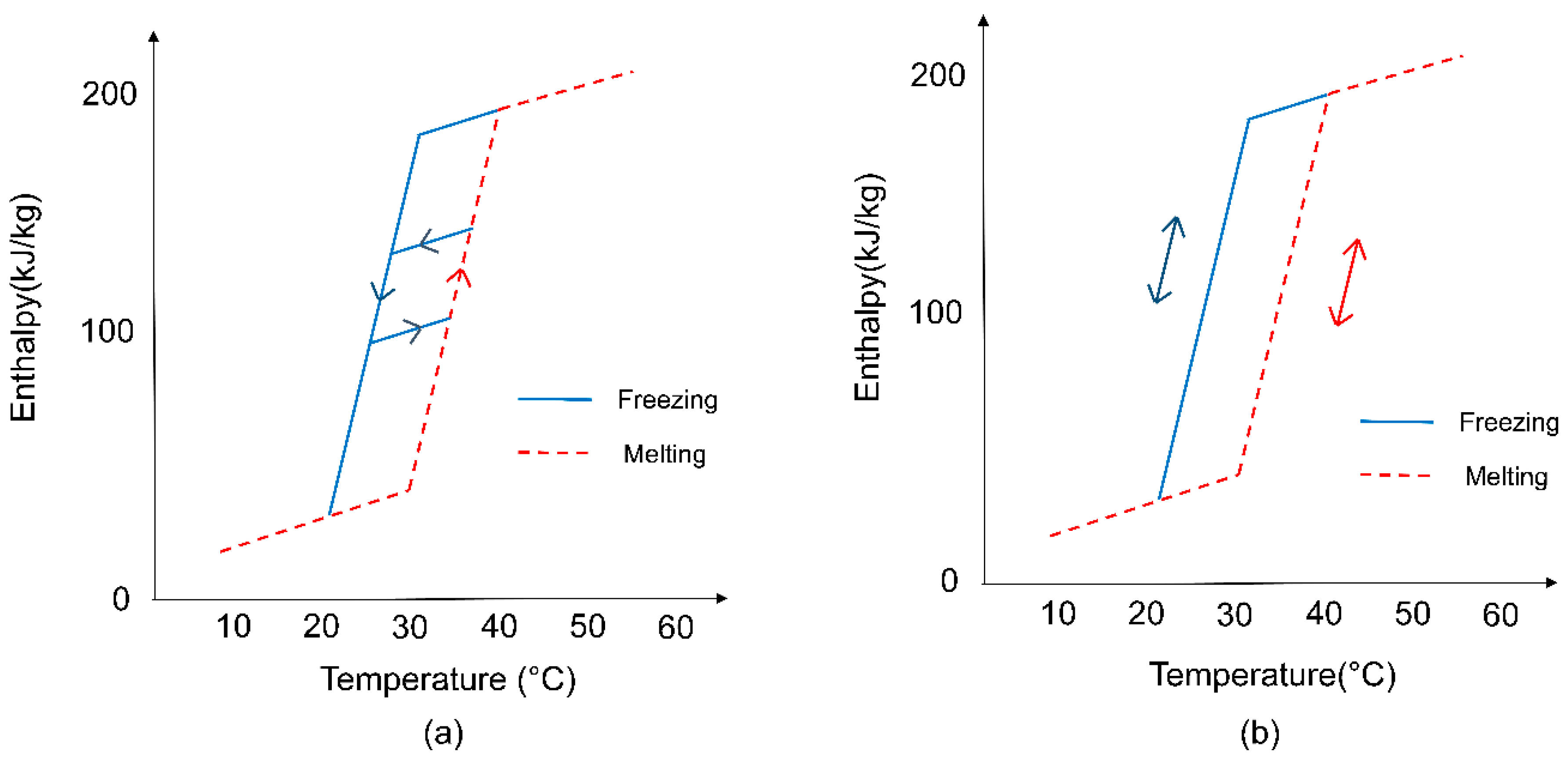
Figure 1. Two approaches to model the transition between melting and freezing processes: (a) Straight transition line model; (b) One curve model.
Energies 13 06455 g001
Figure 2. Locations of the sensors for the monitoring of the PCM air temperatures in the heat exchanger for experimental and simulation cases [31]: (a) front view; (b) side view; (c) top view.
Energies 13 06455 g002
Figure 3. The temperature of PCM at a height of 510 mm in the heat exchanger as a function of time.
Energies 13 06455 g003
Figure 4. The deviation between the models and the experimental data.
Energies 13 06455 g004
Figure 5. The PCM-enhanced ventilated windows (PCMVW) control strategies for both summer and winter applications [45].
Energies 13 06455 g005
Figure 6. The PCMVW and HVAC (heat pump) operation schedule.
Energies 13 06455 g006
Figure 7. The PCM temperature profiles for models with different phase change temperatures for summer night cooling application.
Energies 13 06455 g007
Figure 8. The PCM temperature profiles for models using PCM with different hysteresis degrees for summer night cooling application.
Energies 13 06455 g008
Figure 9. The PCM temperature profiles for models using PCM with different phase change temperatures for winter energy storage application.
Energies 13 06455 g009
Figure 10. The PCM temperature profiles for models using PCM with different hysteresis degrees for winter energy storage application.
Energies 13 06455 g010
Figure 11. The influence of PCM phase change temperature on building energy for severe summer and winter seasons: (a) the heat pump’s energy demand; (b) the energy savings compared to no PCM.
Energies 13 06455 g011
Figure 12. The influence of PCM hysteresis on the building’s energy for severe summer and winter seasons: (a) the heat pump’s energy demand; (b) the energy savings compared to no PCM.
Energies 13 06455 g012
Figure 13. The sensitivity index of phase change temperature and hysteresis degree on the HVAC energy demand: (a) the summer energy demand; (b) the winter energy demand; (c) the yearly total energy demand.
Energies 13 06455 g013
Figure 14. The predicted percentage of dissatisfied (PPD) of the models with different PCM phase change temperatures in transition seasons.
Energies 13 06455 g014
Figure 15. The predicted percentage of dissatisfied (PPD) of the cases using PCM with different hysteresis degrees in transition seasons.
Energies 13 06455 g015
Figure 16. The sensitivity indexes of phase change temperature and hysteresis degree on the PPD: (a) the summer transition season; (b) the winter transition season; (c) the transition season average.
Energies 13 06455 g016
Table 1. The thermal properties of the PCM in the experimental setup [31].
NameParaffin Wax 22
Density820 kg/m3
Specific heat capacity2.3 kJ/kg/°C
Thermal conductivity0.18 W/m/°C
Latent heat117 kJ/kg
Melting range16–23 °C
Freezing range14–21.5 °C
Melting peak21.5 °C
Freezing peak20.7 °C
Publisher’s Note: MDPI stays neutral with regard to jurisdictional claims in published maps and institutional affiliations.