Review

Overview of the Development and Application of the Twin Screw Expander

1
College of Mechanical and Electronic Engineering, Shandong University of Science and Technology, Qingdao 266590, China
2
School of Engineering, University of Warwick, West Midlands, Coventry CV47AL, UK
3
College of Mechanical Engineering, Xinjiang University, Ürümqi 830046, China
*
Authors to whom correspondence should be addressed.
Energies 2020, 13(24), 6586; https://doi.org/10.3390/en13246586
Submission received: 16 November 2020 / Revised: 8 December 2020 / Accepted: 8 December 2020 / Published: 14 December 2020

Abstract

:
With the development of society, the energy crisis has become increasingly prominent, which greatly affects the sustainable development of the economy of various countries. Industrial energy consumption accounts for more than 70% of China’s total energy consumption, of which more than 50% is converted to industrial waste heat, and recyclable waste heat resources account for about 60% of the total waste heat resources, while China’s current utilization rate of industrial waste heat only reaches about 30%. The development of renewable energy and recovery of low-grade waste heat in industry is the key to solve the problem. As a type of volumetric expander with full flow expansion, the screw expander is extensively applied in the industrial waste heat recovery and geothermal energy generation industry because of its effective utilization of low enthalpy energy. Improving the performance of the screw expander as the core, the paper concludes and summarizes the research status of the leakage, rotor geometry, sealing and lubrication, processing and manufacturing, which can affect the performance of the screw expander. In addition, it also introduces the application status and potential utilization of screw expander.

1. Introduction

Since the industrial revolution, fossil fuels such as oil and coal have become the foundation of social development. But with the development of the economy, the current reserves of fossil energy are difficult to meet the demand. Therefore, countries around the world have vigorously developed solar, geothermal and other renewable energy, and have carried out energy conservation work.
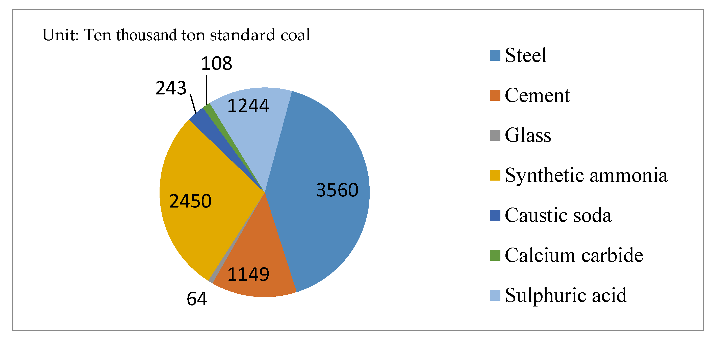
Industrial energy consumption accounts for more than 70% of China’s total energy consumption, of which more than 50% is converted to industrial waste heat, and recyclable waste heat resources account for about 60% of the total waste heat resources, while China’s current utilization rate of industrial waste heat only reaches about 30% [1]. Table 1 shows the heat sources of industrial waste heat and the percentage of fuel consumption in various industries [2]. In the metallurgical industry, the waste heat resources mainly come from rolling steel heating furnace, soaking pit, open hearth furnace and blast furnace, etc., which accounts for more than 33% of the fuel consumption. In the chemical industry, waste heat resources mainly come from chemical reaction heat and combustible chemical heat, etc., which accounts for more than 15% of fuel consumption. In the building materials industry, waste heat resources mainly come from high-temperature flue gas, kiln crow cooling and high temperature products, etc., which accounts for about 40% of fuel consumption. In the glass industry, waste heat resources mainly come from glass melter, enameling furnace and pot furnace, etc., which accounts for about 20% of fuel consumption. Waste heat resources in the papermaking industry mainly come from drying cylinder, steamer, waste gas and black liquor, etc., the waste heat resource in the textile industry is mainly derived from the dryer, slasher, digester, etc., and machinery industry waste heat resources mainly come from the forged reheating furnace, cupola furnace and heat treatment furnace, etc., the respective fuel consumption accounting for about 15%. Most of the industrial heat belongs to low-temperature waste heat, which is difficult to recycle on a large scale. In China, according to the data of the survey report on utilization of industrial waste heat resources, energy resources institute, by 2015, the waste resources of seven surveyed industries were expected to be 340 million tons standard coal, which was equivalent to about 30% of the industrial energy consumption. The amount of waste heat resources in seven industries is shown in Figure 1. During the 11th Five-Year, the industrial waste heat resource utilization rate was 34%, and the utilization of waste heat resources is shown in Figure 2 [2]. If various waste heat resources can be effectively used, not only can it improve the utilization rate of resources, but also effectively alleviate the pressure of the energy crisis.
At present, waste heat can be recovered by using direct heating (commonly preheating or drying operations) or converting medium- and low-temperature heat into mechanical energy or electrical energy (steam Rankine cycle, organic Rankine cycle, Stirling cycle, Karima cycle, flash steam technology, screw expander technology, etc.) [3]. Due to its low boiling point, simple structure and stable operation, organic Rankine cycle shows great potential in the recovery and utilization of waste heat of medium and low temperature [4]. Many researchers have carried out a lot of studies on the organic Rankine cycle from different aspects (such as the types and forms of heat sources, different organic Rankine cycle systems, and the optimization of various parts of the system), and have achieved fruitful results. Shahab Yousefizadeh Dibazar et al. [5] established three types of organic Rankine cycles (basic ORC, ORC with single regeneration and ORC with double regeneration) under the same heat source for research and simulation. The results of advanced exergy analysis show that, compared with basic ORC, regenerated ORC has a high potential to reduce irreversibility. Yong-qiang Feng et al. [6] compared the regenerative organic Rankine cycle with the basic organic Rankine cycle based on a 10kW experimental prototype of the organic Rankine cycle, and the results showed that basic organic Rankine cycle had higher power and power generation efficiency than basic organic Rankine cycle. Mehdi A. Ehyaei et al. [7] have successfully optimized the organic Rankine cycle using geothermal heat sources through energy and exergy analysis. After analyzing the energy and exergy parameters of the geothermal cycle, a two-stage optimization process is carried out. S.M. Alizadeh et al. [8] took Tehran as an example to study the hybrid integration of solar receiver with gas turbine cycle, gas-steam combined cycle and heat recovery steam generator. The application of the heliometer solar receiver is to use solar energy to heat the pressurized exhaust air before entering the combustion chamber, thus generating more steam in the gas cycle and combined cycle. This action reduces the consumption of fossil fuels and reduces the environmental impact of these cycles. L. Di Cairano et al. [9] proposed a reversible cycle in order to overcome the commercial success of the organic Rankine cycle hampered by the compactness and cost requirements of the automotive sector. ReverCycle can be in the standard of the MAC system when the need for cabin cooling and ORC system of mechanical energy in the recovery of waste heat from the engine cooling system of the two different modes.
As the core component of the low-temperature power generation system, the expander plays a vital role in the overall system performance. At present, two main types of expanders are applied in low-temperature power generation systems. The expander is divided into two broad categories: positive displacement (volumetric) expander and velocity-based (turbines) expander [10]. Table 2 shows the comparison of various expansion machines [11]. Velocity-based (turbines) expanders are used in high power and are divided into radial flow type and axial flow type. The radial flow type has the advantages of compact structure, high isentropic efficiency, relatively high single-stage expansion, good sealing and mature processing, but it is expensive, high speed and not suitable for small energy units. Axial flow has the advantages of high entropy efficiency in large units, maximum power in a single unit, large expansion ratio determined by multistage expansion and long service life. However, it has a large number of impellers, high manufacturing cost, high maintenance cost, and large clearance loss and friction loss when used in small units. Positive displacement (volumetric) expanders are suitable for low power. They can be divided into scroll expander, screw expander, slide expander and piston expander. The scroll expander has few moving parts, small loss, low speed, simple manufacturing, low cost and no valve and other advantages, but it needs a lubrication system, small power, and leakage is more serious, there is mainly friction, suction and internal leakage loss. The screw expander has the advantages of being suitable for two-phase flow, high working flexibility and low speed, but it needs lubrication system and high machining precision. Although the slide expander can be applied to two-phase flow, simple structure, low speed and other advantages, its power is small, poor sealing. The piston expander has a high expansion ratio, which can be used in two-phase flow and variable working conditions. However, it has many moving parts, complex manufacturing, heavy losses, heavy weight and flow resistance in inlet and outlet valves. Compared with other volumetric expander, the efficiency is low. As a new type of volumetric expander, the screw expander has the characteristics of simple structure, high volume efficiency. Compared with velocity-based expander, screw expander possesses some advantages. First, unlike vane expander, the contact forces within screw expander are low, which makes it very reliable. Second, the fluid velocities within it are roughly one order of magnitude smaller than those in turbo expander, and thus there is little risk of damage stemming from the admission of liquid/vapor mixtures. Compared with another positive displacement expander, screw expander has also some advantages. First, unlike reciprocating piston expander, all the moving parts of the screw expander rotate so that it can run at a higher speed. Second, unlike scroll expander and slide expander, screw expander leakage loss is relatively small. Due to its unique advantages, the screw expander attracts wide attention and will gradually substitute for the turbines expander in the low-temperature power generation systems such as organic Rankine cycle.

2. The Current Research Status of Screw Expander

With the rapid rise of geothermal power generation technology in the United States, the screw expander has captured increasing attention due to its ability of full-flow expansion. However, due to the influence of rotor profile and rotor machining precision, the performance of the screw expander has so far failed to meet the requirements. Regarding enhancing the performance of the expansion, the study of the screw expander is concentrated in the following areas: (1) leakage of screw expander, (2) rotor profile, (3) processing method and equipment, (4) sealing, (5) thermodynamic model and simulation.

2.1. The Basic Structure and Operating Principle of the Screw Expander

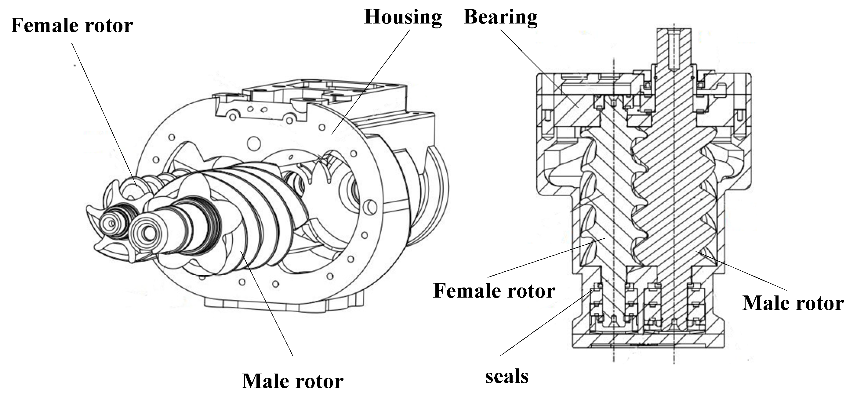
The structure of the screw expander is similar to that of the screw compressor, whose main structure includes the housing, female rotor, male rotor, synchronous gears, bearings, seals and other parts [12]. The cylinder of the screw expander is a “∞” glyph of two circles intersecting, the female and male rotors are meshed by a certain transmission ratio and are parallel to in the cylinder. A portion of the male rotor extends out of the shell for output shaft work. The basic structure of the screw expander is illustrated in Figure 3.
The screw expander operates according to the reverse operating of the screw compressor. As shown in Figure 4, the working process of the screw expander is similar to the scroll expander, which is also split into three stages: suction process, expansion process and exhaust process [13]. The three stages of the screw expander working process are briefly described as follows.
Suction process: the high-pressure working fluid enters the “V” type working chambers A (inlet chamber) from the axial and radial direction of the air inlet that is formed between the housing and female and male rotor. The expansion of the high-pressure working fluid drives the reverse rotation of the female and male rotor, so that the volume of the tooth space continues to expand. When the tooth cuts off the air inlet opening, the working chamber A completely separates from the air inlet, and the air suction process is over.
Expansion process: at the end of the suction process, the working chamber A is filled with high-pressure working fluid, and the female and male rotor continue to reverse rotate under the action of pressure. With the rotation of the rotor, the working fluid enters the working chambers B and C. The volume of the working chambers continues to expand, and the volume expansion temperature of the working fluid decreases, at the same time as the power output by the shaft.
Exhaust process: with the rotor rotating, the working fluid enters the working chamber D. When D is connected to the exhaust port, the exhaust process begins. When the volume of D goes down to zero, this work cycle ends.

2.2. Research on Leakage of Screw Expander

For the screw machine, due to many factors such as lubrication and installation accuracy, there is always some gap between the rotor and the rotor and between the rotor and the housing. Because of this gap, the leakage of the screw expander is inevitable. Leakage clearance size determines the size of the leakage, and the size of the leakage is the most important factor affecting the performance of the expander. Therefore, many scholars have conducted extensive research on the leakage of the screw mechanism.

2.2.1. Research on Screw Mechanical Leakage

Fong et al. [14] proposed a new mathematical procedure for calculating the inter-lobe clearance between two screw rotors, and described the clearance field with the iso-clearance contour diagram (ICCD). The geometrical and kinematical relations of mating rotors were calculated by the theory of gearing and the tooth contact analysis (TCA), and the contact lines and the approximate blowhole were calculated by TCA.
JanPrins et al. [15] used the method of an experiment to measure the size of the housing sealing line gap that directly related to the rotor profile, and the indicated diagram of leakage gap size was obtained by analyzing the experimental data. The analysis and discussion of the influence of leakage on the compression line of the indicator diagram were emphasized.
Based on the assumption of a uniform property annular-shaped region at the labyrinth entrance, Yafen Tian et al. [16] proposed a method for leakage flow rate prediction at the discharge end-face of twin-screw compressors. Assumption of such a region was the key aspect in the construction of an equivalent network of end-face leakage flows, in which the labyrinth entrance zone is a node. Using mass and energy conservation laws, the thermo-physical properties of the average-state region (ASR), the leakage paths flow rates were determined.

2.2.2. Computer-Assisted Application in Leakage Research

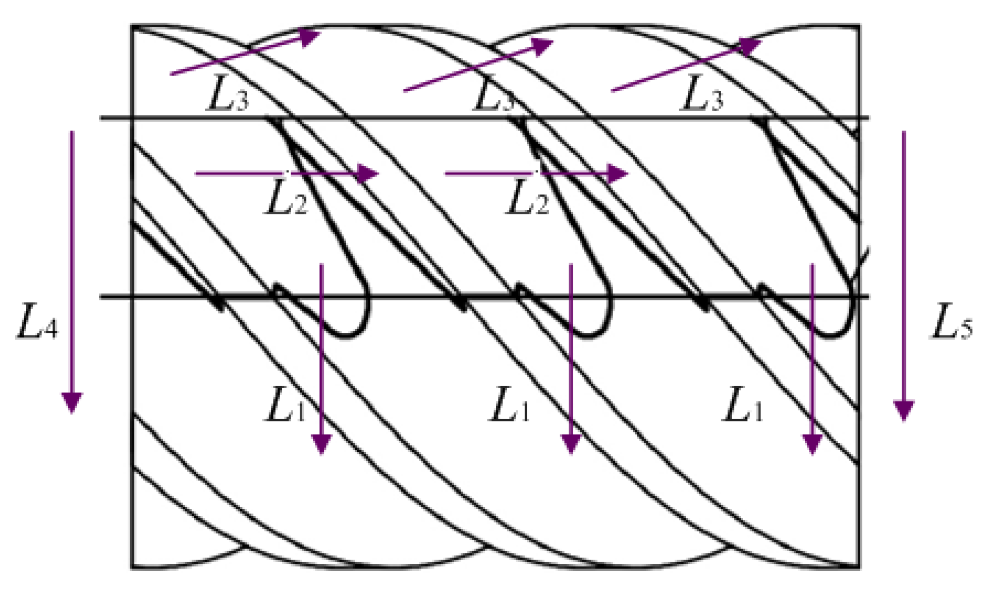
The leakage characteristics of twin screw compressor were studied by using the calculation design software (SCCAD) of a screw compressor. According to the structural characteristics of the twin screw compressor, Xing et al. [17] defined the leakage channels (L1, L2, L3, L4, L5) of the five twin screw compressors, as shown in Figure 5 and established the mathematical model of leakage channel with the leakage characteristic. Additionally, the length of leakage channel, the leakage area and the leakage amount were calculated by using the SCCAD software, and the influence of leakage flow rate of each leakage channel on mechanical efficiency was analyzed and calculated.
To analyze the geometrical parameters screw expander rotor, Qi et al. [18] used Pro/Engineer (PROE) software to establish a three-dimensional geometrical model of twin screw expander and to measure the change of base element volume, inlet orifice area and leakage area with the rotation angle of the male rotor. Then, according to the geometric parameters, a thermodynamic model based on continuity and energy conservation equation is established.
Based on the simulation analysis of the three-dimensional CFD model of the screw expander, Papes I [19] studied the mass flow of four types of leakage channels. Dr. Hesse et al. [20] researched the heat transfer between gas and rotors and leakage flows through the clearances by CFD model of screw compressor simulation analysis. The simulation results show that the leakage mass flows for the four male rotor gaps (sum of axial and radial part) and six female rotor gaps; gap mass flows up to 3% of total mass flow can be seen on male rotor and up to 2% on female rotor.

2.2.3. Research on the Leakage of Working Fluid Condition

Most researches on screw machine leakage are based on single-phase gas or single-phase liquid. Whereas, the real condition of working fluid of the screw machine is a mixture of oil and gas. The leakage state of the hypothesis is quite different from that of the actual leakage state.
To solve this problem, Li et al. [21] provided a method for judging flow state of the leakage channel by comparing the relative size of the gap height, the thickness of the oil film and the leakage time. If the gap height is less than the thickness of the oil film, it is considered that the leakage is only a single-phase oil leakage. Otherwise, the oil and gas leakage can be calculated separately for the stratified flow of oil and gas, and then the total leakage of oil and gas can be obtained after the superposition.
For the convenience of calculation, Wang et al. [22] treated the two-phase mixture as the homogeneous flow, and assumed that oil and gas are mixed evenly without phase transition. Based on this, the thermodynamic equilibrium between the two phases was achieved.
Bein et al. [23] calculated the gas leakage from the exhaust process by the nozzle flow model, and corrected the influence of the existence of the actual lubricant on the gas leakage through empirical coefficient. However, there are too many uncertainties in the empirical value, which results in a large deviation from the actual leakage.

2.3. Research Status of Rotor Profile of Screw Expander

The screw rotor can be considered to be obtained by spiral scanning of the outer ring profile of the rotor end around its axis and stipulates that the outer contour of the screw rotor end is the rotor profile. The rotor profile directly determines the geometric parameters, which decide the size of the leakage, such as the leakage triangle and the contact line length, etc. Therefore, the rotor profile determines the performance of the screw expander to a large extent [24].

2.3.1. Development of the Rotor Profile of Screw Machine

Since the successful design of the symmetric circular arc line in the 1930s, the new profile has been emerging with the continuous deepening of the research on the rotor profile. Throughout the history of the development of the rotor profile, the rotor profile design mainly experienced three stages [25].
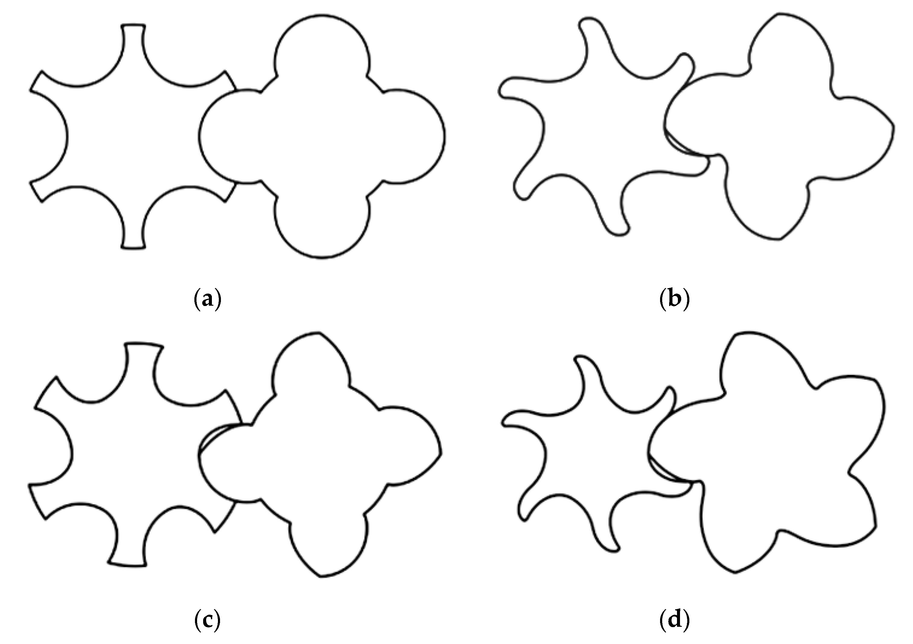
The first stage is a symmetrical circular arc profile, as shown in Figure 6a. The type line is mainly composed of an arc and the mutual engagement of the arc envelope line together. The rotor profile of male rotor and female rotor are symmetrical. Because the design, manufacture and measurement of this profile are relatively straightforward, so far, the type line has been applied in some dry compressor production.
The second stage is an asymmetric profile. This profile is composed of points, lines and cycloid lines in different connection order. The contact type of the unsymmetrical tooth-shaped rotor is surface contact, which not only highly reduces the stress of the contact surface during torque transmission but also greatly reduces the area of the leakage triangle. The typical representative of asymmetric lines has SRM-A profile and unilateral asymmetrical cycloid, as shown in Figure 6b.
The third-stage rotor profile is a new asymmetrical profile, and it is also called a high efficient new tooth type. The design basically adopts circular, parabolic, elliptical curves and abandoned points, straight lines, cycloid, and so on. So, the rotor tooth surface is changed from “line seal” to “surface seal”, which effectively improves the sealing ability, thereby improving the performance of the screw expander. Representative lines of this profile are GHH, SRM-D, Hokuetsu and X31 and X32 profile developed by Xi’an Jiao Tong University. Figure 6c,d show GHH and Hokuetsu profile.

2.3.2. Research on the Rotor Profile of Screw Machine

To measure the efficiency of the rotor profiles, there are the following criteria: (1) small contact stress; (2) good torque transfer performance and oil film forming ability; (3) shorter contact lines; (4) large volume cavity; (5) easy processing and manufacturing. The above five are not only the criterion of rotor profiles efficiency, but also the principle of rotor profiles design. Based on the above design principles, many scholars apply new methods, new thoughts and new tools for optimization and redesign of the rotor profile.
(1)
The application of the new method to the study of rotor profile
By analyzing the meshing line of the rotor, D. Zaytsev et al. [26] proposed a new method for generating the rotor profile. Furthermore, requirements of the meshing line were listed and an analysis was carried out to obtain optimal profile design. The feasibility of this method is verified as well.
Stosic N et al. [27] adopted mutual engagement principle of gear in the design of screw rotor profile, thus they successfully developed the spiral rotor of “N” line series. The series have the characteristics of larger flow area, smaller leakage triangle, and smaller internal friction. In addition, the “Scorpath” software was successfully designed and developed.
Litvin et al. [28] gave the vector expression of the rotor profile and studied the characteristics of the rotor profile and the influence of the inter rotor contact clearance on the performance of the compressor.
(2)
The application of computer-aided design in the design of profile
Recently, computer technology has played a very important role in the optimization of the typical profile and the development of the new profile. Application of computer technology in rotor profile design not only improves the design efficiency, shorten the design time and improve the design precision, but also predict the performance of the rotor.
He Xueming et al. [29] summarized the general equation, general fitting equation, conjugate line and meshing line equation of rotor line based on the comprehensive analysis of the common profile equation and the conjugate relation of screw compressor rotor. Through the use of general equations and the corresponding supporting software, three tooth shapes of JB, SRM and HZ-3 were designed and plotted.
A complete set of screw rotor design and calculation software (SCCAD) was developed by Xing et al. [30] of Xi’an Jiao Tong University’s compressor teaching and research office. The software can automatically complete the design of the rotor profile, calculation of the geometry of the rotor and the prediction of power and thermal performance.
Based on the analyses of some typical rotor profiles and gear engagement theory, He Xueming et al. [31] introduced a method to generate the rotor profiles by using media rack. A new type of twin-screw compressor rotor profiles was designed by means of optimization method. Calculation and intermeshing behavior simulation were done with the software Matlab and Pro/Engineer.
(3)
The reverse design of rotor profile
Most of the traditional design method of profile belongs to a kind of top-down design, but this method requires a significant amount of effort on the selection of curves and experimental verification, and the computing process is very complex. Through practical verification, the reverse design not only completes the optimization design of products based on the digital model but also avoids some detours in the top-down design, and thus is able to shorten the design cycle and reduce the design cost.
The data acquisition method and processing technology of profile were studied by Jia Chunyang [32]. The reverse design method of the rotor profile— Non-Uniform Rational B-Splines (NURBS), was put forward based on the reverse design idea after the data fitting of the screw rotor profile, which provided a theoretical basis for the reverse design of the rotor profile.
From the meshing line of the twin-screw compressor rotor of view, He Xueming et al. [31] introduced the method of meshing line in detail and deduced that rotor profile of yin-yang rotor form the meshing line through meshing and coordinate transformation.
Shi Guo-jiang et al. [33] based on Microsoft Visual 2010 and its Microsoft Foundation Classes (MFC) module, combined with the graphics display function of OpenGL, and on the basis of the previous design ideas for innovation, designed a set of twin-screw compressor yin-yang rotor type line design system (TSD).

2.4. Research Status of the Machining of the Screw Rotor

Processing accuracy of the screw rotor has a significant influence on the leakage gap, seal, friction of the screw mechanism. The requirement of screw rotor for machining accuracy is very high. In the early stage of the development of screw mechanism, due to the limitation of the machining methods and processing equipment, it is difficult to fabricate even new line with good performance. The mechanical performance and efficiency of the screw mechanism was low, which seriously impeded the development of the screw machine. With the development of the Computer Numerical Control (CNC) machine technology, professional screw rotor processing equipment has successfully been developed, and corresponding new screw processing methods have been proposed, so the accuracy and performance of the screw rotors have obtained the significant enhancement.

2.4.1. Machining Method of the Screw Rotor

Screw rotor profile is composed of several curves, and rotor profile makes a spiral motion along the rotor axis to form a screw rotor. The screw rotor has the characteristics of low helical tooth number and large spiral angle. Currently, milling, rolling, grinding, coating method and precision casting are commonly used machining methods for screw rotor [34,35].
The milling processing method is divided into disc cutter processing method and finger cutter processing method. When the screw rotor is processed by disc milling cutter, there is a space interlacing with a certain angle between the tool axis and rotor axis, the disc cutter rotates around the cutter shaft, and the rotor makes a spiral movement. Finger milling cutter processing screw rotors are normally made on vertical milling machines. The cutter axis is perpendicular to the horizontal axis of the rotor when the rotor is machined, the finger shape milling cutter revolves around the cutter axis, at the same time, the rotor motion according to the spiral rotor gear tooth surface characteristics.
When the screw rotor is machined using hob, the milling cutter can continuously cut the tooth surface of the rotor, which is the reason that the rotor machining efficiency can be further improved by the rolling process. To ensure the machining efficiency of the rotor and the service life of the cutter, it is required that the shape of the rotor have excellent machining performance and a straight segment cannot appear. Therefore, the processing type of the screw rotor is limited. In addition, the processing of the hob is sophisticated, and the production costs are relatively high, only suitable for small rotor production.
The grinding method not only has high machining efficiency but also makes the rotor have a higher precision of tooth surface. The cost of cutting tool is relatively low compared with the cutting tool. Furthermore, the grinding process can be reprocessed on the surface of the rotor surface treated by heat treatment, so that the manufacturing precision of the finished rotor is greatly improved. Moreover, the good stability and forming process of grinding can obtain more reasonable rotor engagement clearance. The grinding process has a deep grinding function, which applies to different types of profile, and it is the leading edge of the current rotor machining technology.

2.4.2. Profiler Design of Rotor Machining Tool

It is difficult to process the screw rotor because of the complicated machining principle and the uncontrollable machining process. However, the forming milling method can meet the requirements of both efficiency and machining accuracy and is the most common method of the manufacturing process of the rotor [36]. In order to adapt to the complex helical surfaces of different screw rotors, higher requirements to the cutting edge, process performance and life span of milling tools are put forward, and many scholars have carried out extensive research.
Song [37] from Dalian Jiaotong University used the unilateral asymmetric cycloid pin gear arc line as the research object, the milling cutter profile equations were solved using the envelope method. The method of equidistant clearance of the rotor meshing was proposed by modifying the milling cutter blade.
Wang [38] established mathematical model of the relative motion trajectory between the cutter and workpiece in the space without instantaneous center envelope milling process and the mathematical relationship model between the cutter path and the workpiece profile.
With the development of computer technology, CAD/CAM has been widely used in optimization design of rotor machining tool profile. Shetha et al. [39] presented mathematical analysis as the basis for a CAD/CAM system for design and manufacture of components with helical grooves. The system helps the user design the profile of the tool or the helical groove, and after that analyzes the subsequent machining process.
Shan et al. [40] studied the calculation and simulation of the spiral face forming milling cutter and obtained the formula of the milling cutter by using the enveloping principle. Kuang et al. [41,42] developed the contact equation of the contact line between the helical surface and the revolving surface of the cutter based on the theory of the forming milling envelope and obtained the contour of milling cutter by MATLAB.
Li et al. [43] introduced parametric design method of cutter profile for screw rotor forming milling. The feasibility of cutter profiler was validated by realized the 3D simulation machining of the spiral groove by using AutoLISP language in AutoCAD 2004. In-depth study of the cutter profiler design, screw machining and geometric modeling was carried out by Zhang Lina, Lee Y S, et al. [44,45].

2.4.3. Advanced Professional Screw Rotor Processing Equipment

At present, the screw rotor processing method and the complete set of professional processing equipment and technology are mature. But its related equipment is mostly monopolized by the established industrial powers such as the US’s ROBBING&MYER, UK’s HOLROYD, Germany’s LEISTRITZ, Germany’s KAPP and Germany’s KLINGELNBERG [46,47].
British’s HOLROYD is a company with strong strength and a long history of screw manufacturing. The TG350E CNC screw grinder developed by HOLROYD can complete the machining of the rotor surface with high effective and high accurate, and the technical requirements of the operator are not high. The maximum statistical error of grinding machine is ±4 μm, and the error of the guide process is less than ±2 μm. TG350E CNC screw grinding machine consists of mechanical system, control system, grinding wheel dressing system, precision grinding system and online measurement system. The grinding machine can automatically check the alignment of the workpiece, the rotor feed into the line is correct and the alveolar positioning is accurate. It can also perform a tooth scan, online measurement of rotor diameter, depth, pitch and groove, and the real-time feedback of data to the control system, to ensure accurate and rapid modification of tooth shape.
Kingelnberg of Germany is a professional thread grinding machine manufacturer. This company develops the HN35 series CNC screw rotor grinder, which is mainly composed of grinding wheel dressing system and precision grinding system. The grinding machine can directly and forcefully grind all kinds of different types of rotor without rough machining. Although there is an online measurement system, the machine tool can be used to evaluate the rotor grinding quality and the zero-position judgment with the p-series gear measurement center of the development. So, it can also meet the high precision machining requirements of the rotor.
The KAPP-RJ59 CNC screw rotor grinder produced by KAPP of Germany. It is used to process the screw rotor with high-speed grinding of the Cubic Boron Nitride (CBN) grinding wheel, and the coarse grinding and fine grinding of the rotor by two pieces of forming grinding wheel at the same time. The surface of forming grinding wheel decorated with diamond particles. After abrasive grain abrasion and shedding, the coating needs to be reapplied. The rotors can be measured online by the measuring system configured on the machine. Its advanced design concept makes the machine machining rotor with high efficiency and precision.
China Hanjiang Machine Tool Co., Ltd. exhibited SK7032 CNC screw rotor grinder with independent intellectual property rights in Nanjing, China CNC Machine Tool Show CCMT2010. However, SK7032 still adopts the process method of grinding wheel repair and screw rotor grinding separately. It is necessary to manually change cutter and calibration cutter repeatedly, and it does not have an online detection function. There is a large gap compared to the professional processing equipment of screw rotor, such as UK and Germany [48,49].
The performance comparison of screw rotor grinding machine of four companies is shown in Table 3.

2.5. Research on Seal of Screw Expander

The sealing component is a critical part of the screw expander, and it is also the vulnerable part of the expander. The quality of the seal structure and seal directly affects the economy and reliability of the expander. When the screw expander is applied to the double cycle system such as the organic Rankine cycle and the Kalina cycle, most organic working fluid has toxic, flammable and explosive properties. If leaks of toxic and harmful gases such as butanone and toluene are caused due to sealing component problems, not only environmental pollution but also serious accidents such as fire and personnel poisoning may be caused. At present, the main sealing methods of shaft end seal of screw mechanical are labyrinth seal, floating ring seal, mechanical seal, carbon ring seal, dry gas seal, etc. [50,51].
Labyrinth seals have the advantages of reliable work, simple structure, low energy consumption, and it can be applied to the working conditions of high speed and high temperatures. However, the defect of the labyrinth seal is still obvious. The leakage of the labyrinth is large, which is not suitable for the sealing of poisonous and harmful gases. When the particle is sucked into a labyrinth seal, it not only causes damage to the sealing elements but also contaminates the working fluid.
The optimal working condition of the mechanical seal is “semi-liquid working condition.” For pure gas working fluid, the mechanical seal has poor lubrication performance and serious friction of sealing end face, so its application under high pressure and high speed is limited.
Due to the limitations of labyrinth seals and mechanical seals, carbon ring seals and dry gas seals have received the attention of people. Carbon ring seal is a floating ring seal, with simple operation and maintenance, sealing good advantages, and it can be widely used in the flammable, toxic medium sealing way.
Full of the dry gas seal is called dry running non-contact gas seal, which is a new type of non-contact seal. The dry gas seal was developed based on mechanical seal and spiral groove thrust bearing principle. Dry gas seal has advantages of long service life, stable operation and small sealing power. Compared with other seals, gas leakage of the dry gas seal is tiny, and can realize the zero escape of the medium. It is an environmental protection type seal.
With the continuous development of screw machinery, its application continuously expands, and the types and working state of the working fluid are becoming more and more complex and diverse, so the single sealing method is difficult to meet the requirements. In order to meet the requirement of screw mechanical seal, some improvement and optimization are required. Several companies in the United States, Japan, Germany, Sweden and other countries have optimized the sealing of the screw mechanism. Below the shaft seal system of United States I-R (Ingersoll Rand) Company and Japan’s Kobelco will be briefly introduced [52].
  • Four sealing systems of the United States I-R (Ingersoll Rand) company
    (1)
    Standard labyrinth seal: The standard labyrinth seal is largely applicable to dry air, nitrogen and dry vacuum conditions. It can also apply to any dry gas that is not dangerous and can be allowed for a small amount of leakage.
    (2)
    Labyrinth water ring seal: this seal combines with the stainless-steel rotary tooth groove and the babbitt metal stationary bushing. On this basis, a water ring is added to prevent working fluid from leaking along the axis.
    (3)
    Drive gas labyrinth seal: the seal can arrange injection air or inert gas, which is slightly higher than the screw mechanical exhaust pressure, to prevent leakage. This seal is suitable for harmful and combustible materials, which are not allowed to leak into the atmosphere.
    (4)
    Mechanical seal: this seal is suitable for a place where the working medium is toxic or expensive or the drive gas labyrinth seal that cannot be used. The mechanical seal is applied to a rotating sealing ring that is in perpendicular contact to the fixed surface, and an independent lubricating oil system for pressurizing and cooling seals, which includes a motor-driven oil pump, filter, cooler and fuel tank.
The four typical sealing methods of the United States I-R company are shown in Figure 7.
2
Two kinds of sealing systems of the Japanese’s Kobelco company
(1)
Bearing oil film seal: the seal depends on the oil film to prevent gas leakage, and it is used to buffer the gas that does not spoil the oil.
(2)
Mechanical sea: this sealing system applied in this situation that the buffer gas cannot be used or the oil is not allowed to enter the working chamber. The mechanical seal takes lubricating oil as the sealing liquid, and the material of the sliding parts is usually made of graphite carbide. Due to the excellent sliding member material, even in case of high-speed operation, it also shows its good stability.

2.6. Study on Thermodynamic Model and Simulation Analysis of Screw Expander

2.6.1. Research on the Thermodynamic Model of Screw Expander

In the early study of screw machine, most of the research on the thermodynamics and dynamics of screw mechanics focused on the screw compressor, and the research on screw expander was relatively small. Based on a large amount of experimental data, Dunbar and Smith et al. [53] studied the parameters and thermodynamic models of the screw expander. However, the accuracy of the thermodynamic models was poor because it did not consider the influence of leakage, friction, oil and gas exchange heat and other factors.
Ziviani D et al. [54,55,56] considered the leakage loss, friction loss, heat transfer of screw expander, and the thermodynamic model of a screw expander adiabatic expansion process, adiabatic non-isentropic expansion process and leakage and flow loss were established. Through simulation analysis and experiment verification, the results show that the established thermodynamic model had higher accuracy than the previous one.
Tian et al. [57] developed a thermodynamic mathematical model to study the performance of twin-screw steam expander under fluctuating operating conditions. In the modeling, the suction pressure loss is taken into account, as well as leakage and heat transfer during the two-phase expansion process. Simulation results show that the filling factor varies 0.82–0.88 and isentropic efficiency varies 0.73-0.83, which proves that the twin-screw expander is an efficient technology in steam pipeline pressure recovery application.
Guo et al. [58] established a mathematic model of the expansion process of screw expander. Based on the mathematical model, they studied the influence of cross-sectional area of intake and exhaust holes and the drag coefficient on the efficiency of screw expander by numerical simulation.

2.6.2. Research on Simulation Analysis of Screw Expander

Geometric modelling is the foundation of the three-dimensional Computational Fluid Dynamics (CFD) analysis of screw expander, and computer-aided design could provide benefits for accurate identification of geometric parameters.
Buckney et al. [59] calculated geometric parameters of screw compressor such as volume, gradient and cross-section, leakage flow, and blow-hole areas by 3D Computer-Aided Design (CAD).
Seshaiah et al. [60] carried out mathematical analysis of the oil injected twin-screw compressor on the basis of the laws of perfect gas and standard thermodynamic relations to analyze the effect of certain compressor operating and design parameters on the performance. They concluded that inter-lobe clearance and rotational speed greatly affect the efficiency and P-V diagram.
Papes et al. [61] presented a multi-chamber mathematical model of a twin screw expander to predict its performance. In order to calculate the mass flow rates through leakage paths more accurately, flow coefficients used in the converging nozzle model were derived from 3D Computational Fluid Dynamic (CFD) calculation. The maximal deviation between predictions by the developed model and 3D CFD calculations of the complete machine is around 5% for the mass flow rate and the power output.
Kovacevic et al. [62] built the 3D Computational Fluid Dynamics (CFD) of twin screw expander to estimate pressure-angle diagrams, mass flow rates and expansion power at different operating conditions and obtain the overall performance predictions by simulation agreed very well with measured data.
Nikolov et al. [63] analyzed the influence of the thermal deformation on the machine performance, in particular based on an iterative coupling of thermodynamic and thermal simulations. The results of the thermodynamic simulation, mainly based on the so-called chamber models, represent the thermodynamic and fluid dynamic performance of the screw machine by means of mass and energy conservation.

3. The Application of Screw Expander

In 1934, Lysholm, a Swedish professor, proposed the theory of asymmetric helical screw compressor, which laid the foundation for the development of the screw expansion machine [64]. In 1952, H.R. Nillsen obtained the invention patent of the screw expander as the motive power machine, which represents the beginning of the study of the screw expansion machine. But over the next 20 years, the development of the screw expander was very slow. By the 1970s, due to the outbreak of the energy crisis, the development and utilization of renewable energy and waste heat resources have attracted more and more attention from the society. During the period from 1971 to 1973, two screw compressors were changed into expander by the American water heat power company, and field experiments were carried out in California’s Imperial Valley and Mexico’s Cerro Prieto, which proved the feasibility of screw expander application. Since then, it has entered the upsurge of research on screw expander. At present, the screw expander has achieved great progress in the application of industrial surplus power generation, renewable energy generation, industrial waste heat recovery and other fields.

3.1. The Application of Screw Expander in the Low-Temperature Generation System

3.1.1. The Application of Screw Expander in Industrial Residual Pressure Power Generation

The Industrial residual pressure mainly includes the high-pressure natural gas, process gas in the steel and chemical industries, the saturated steam and superheated steam. To meet certain technological requirements in the industry, it is usually necessary to reduce the pressure of these high-pressure gases through the pressure-reducing valve, which results in the waste of the pressure energy. The screw expander can be used as a pressure-reducing valve, which not only can achieve the purpose of reducing the pressure of steam but also effectively convert the industrial residual pressure into the mechanical energy and electric energy.
As shown in Figure 8, Jiangsu Chengxing Phosphoru—Chemical Co. Ltd. installed a screw expanding power generator by using four screw expanders (two KES900, one KES1400 and one KWS2300 screw expander). The generator set is divided into two stages to recover the residual pressure of the by-product steam of the phosphorus burning furnace to generate electricity. The total installed power of this unit is 5.5MW, and the net generating capacity is 4.4 MW [65].
In addition, since Xinyu Iron and Steel Co., Ltd. installed the first screw generator in 2005, a total of five sets of screw expansion power generators have been installed and operated by Xinyu Iron and Steel Co., Ltd. The total power of the power station reaches 2700KW, the annual effective power generation is about 15 million degrees, and the economic and social benefits are all considerable [66].

3.1.2. The Application of Screw Expander in Industrial Waste Heat Recovery

In China, the total resources of industrial waste heat accounts for 17–67% of fuel consumption, and the recyclable part accounts for about 60% of the total residual heat. Therefore, China has a great potential for waste heat application. The screw expander can directly or indirectly generate electric energy by using the industrial hot water, hot oil, atmospheric steam, waste gas and combustible waste gas. Especially, the ORC screw expansion unit is widely used in industrial waste heat recovery.
China petroleum and chemical corporation, Beijing Yanshan branch (Figure 9), adopts the single-stage ORC expansion power generation scheme [65]. In this scheme, the hot oil with a temperature of 135 °C and a flow of 125 t/h is directly introduced into evaporator and preheater. In the evaporator, hot oil and organic medium are heat exchange to produce high-pressure and high-temperature organic vapors, which drive the expander to rotate, thus driving the generator to generate electricity. The total installed power capacity of screw expander generator set is 900 KW, and the annual net power capacity is 4.73 million KW, which can save 1656 tons of standard coal, and reduce CO2 emissions by 3934 tons.

3.1.3. The Application of Screw Expander in Renewable Energy Generation

With the continuous improvement of screw expander technology, the screw expander has been widely used in renewable energy generation fields such as geothermal power generation and biomass power generation. A typical example of the application of screw expander in the new energy power generation is briefly introduced below.
(1)
The Application in the Geothermal Power Generation
As shown in Figure 10, The Alaska Chena hot spring geothermal power generation unit adopts the single stage ORC expansion power generation scheme [65]. The description of the scheme is as follows: Firstly, the hot water at 82 °C is directly poured the evaporator and preheater of the ORC power generation system. Then, the hot water exchanges heat with the organic working medium (R245fa) in the evaporator to form high-pressure, high-heat organic vapor. In the end, high-temperature and high-pressure organic steam drive expander work to produce electricity. The total installed capacity of the screw generator unit is 400 KW, and the net generating capacity is 312 KW.
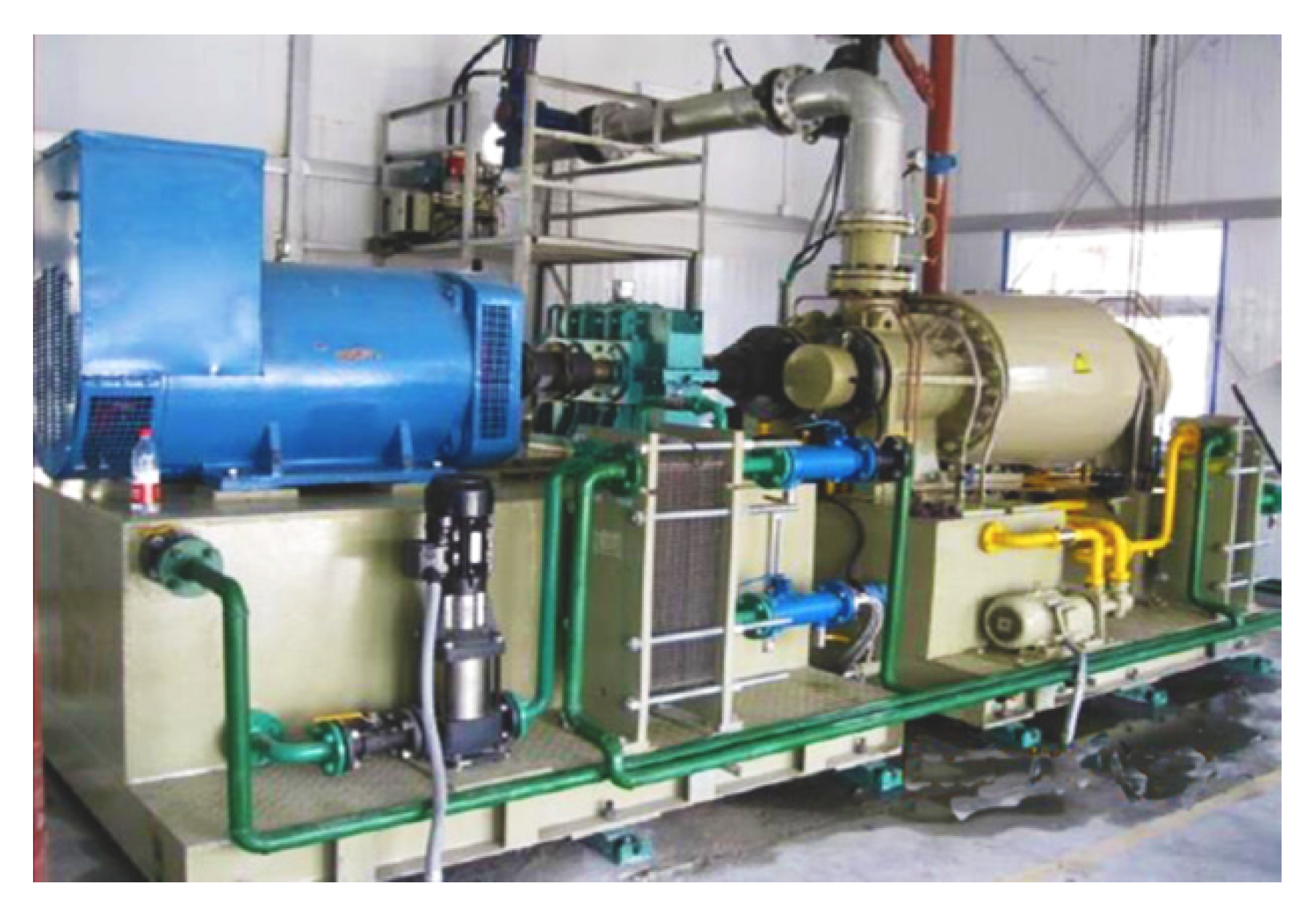
Under the support of Chinese government, the first screw expander generating unit with the capacity of 1MW, manufactured by Jiangxi HuaDian Electrical Power CO. Ltd., was put into operation in YaBaJing for geothermal power generation in September 2008 [67]. The screw expander generating unit produces real power of 940 kW with actual operation parameters of inlet pressure 0.36 MPa, outlet pressure 0.09 MPa and the mixture flow rate 28 t/h. Figure 11 shows the running screw expander generating unit with the capacity of 1MW in YangBaJing geothermal power plant. The second screw expander generating unit with the same capacity was put into operation in October 2010. This generating unit produces real power of 800 kW with operation parameters of inlet pressure 0.39 MPa, outlet pressure 0.09 MPa and the mixture flow rate 22 t/h. Figure 11 shows the second running generating unit in YangBaJing geothermal power plant [67].
The well ZK200 was drilled and completed with the depth of 606 m twenty years ago, having a total mixture flow rate of 95 t/h, a temperature of 134 °C and corresponding pressure of 0.26 MPa at the wellhead. In June 2011, a special recovery processing of ZK200 was conducted and a testing full-flow screw expander unit of two-phase mixtures with the capacity of 400 kW, which is much more suitable for two-phase geothermal sources, was installed at the wellhead and put into operation in September 2011. Figure 12 shows the running testing unit in YangYi geothermal field. After the successful running of the testing screw expander generating unit in Yangyi, another same kind of generating unit with the capacity of 500 kW, which takes the container type with the function of black start, was trial manufactured by Jiangxi HuaDian Electrical Power CO. Ltd. and successfully put into operation in Yangyi in August 2012. It is becoming more convenient for transportation and installation. Figure 12 shows the testing container type of screw expander generating unit in YangYi.
(2)
Application in biomass power generation
As shown in Figure 13, the Buluan biomass power plant in the Philippines adopted two schemes to generate electricity by using the screw expander [65]. The first scheme: Take the temperature of 226 °C, flow of 30 t/h of saturated steam as the heat source, through the tertiary ORC screw expander power generation. In this scheme, the total installed power of the unit is 3.51 MW, and the net power generation is 2.5 MW. The second scheme: With the temperature of 115 °C, the flow rate of 4.3 t/h of saturated steam as the heat source, configure an ORC screw generator set to generate electricity. In this scheme, the total installed power of unit is 400 KW; net power generation is 350 W. Above is the first phase of the Philippines Buluan biomass power plant, and the second phase is under construction.

3.2. Potential Utilization Field of Screw Expander

3.2.1. The Field of Solar Power Generation

Solar energy is a kind of eternal energy and also a kind of pollution-free and environment-friendly energy. The earth gets about 6 × 10¹⁷ kW per year from the sun, but it is rarely used efficiently by humans, so solar energy has a huge amount of reserves and high potential for exploitation. Table 4 shows the utilization and development forecast of solar energy in the world [68].
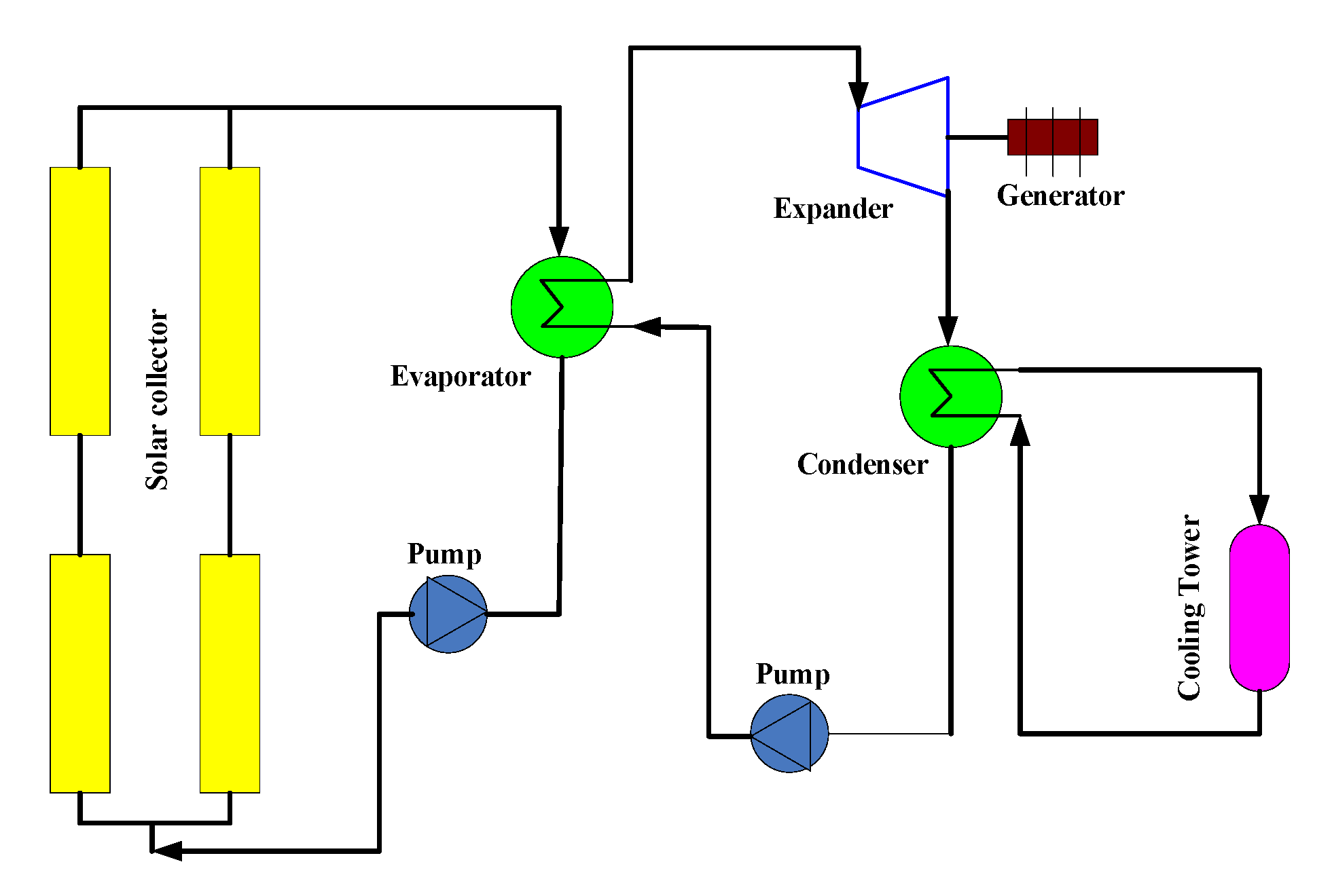
Figure 14 is the principle of low temperature and thermal power generation system based on the solar energy [69]. The operating principle can have a simple description: solar energy is collected through solar collectors and be used as the heat source of ORC system. In the evaporation, heat exchange between solar energy and organic refrigerants to form high-pressure steam, which drives the expander to do work. The power of the turbine expander is too high and is not suitable for the small- and medium-capacity solar power system. The power range of the screw expander is 1 kW–200 kW, which is very suitable for the small and medium ORC power generation system [70,71,72]. It has contributed to the miniaturization and decentralization of solar power generation.
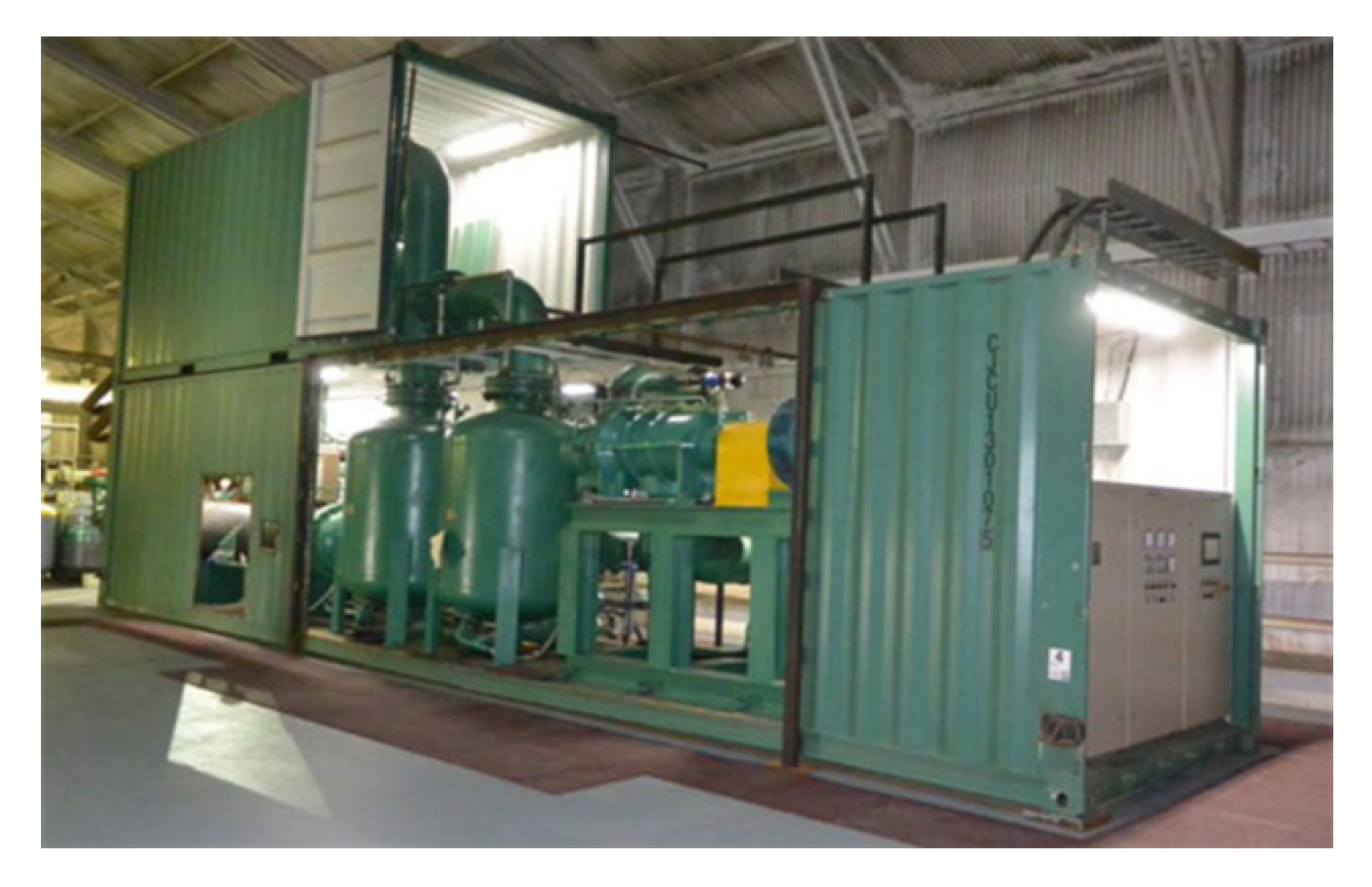
The Lanzhou screw expander solar thermal power generation project (Figure 15) is one of the typical cases of screw expander applied to solar power generation. The project has a rated power of 160 KW, an annual power generation of 1.28 million degrees, and a reduction of 1064 tons of CO2 emissions [73].

3.2.2. The Field of Ocean Thermal Energy Conversion

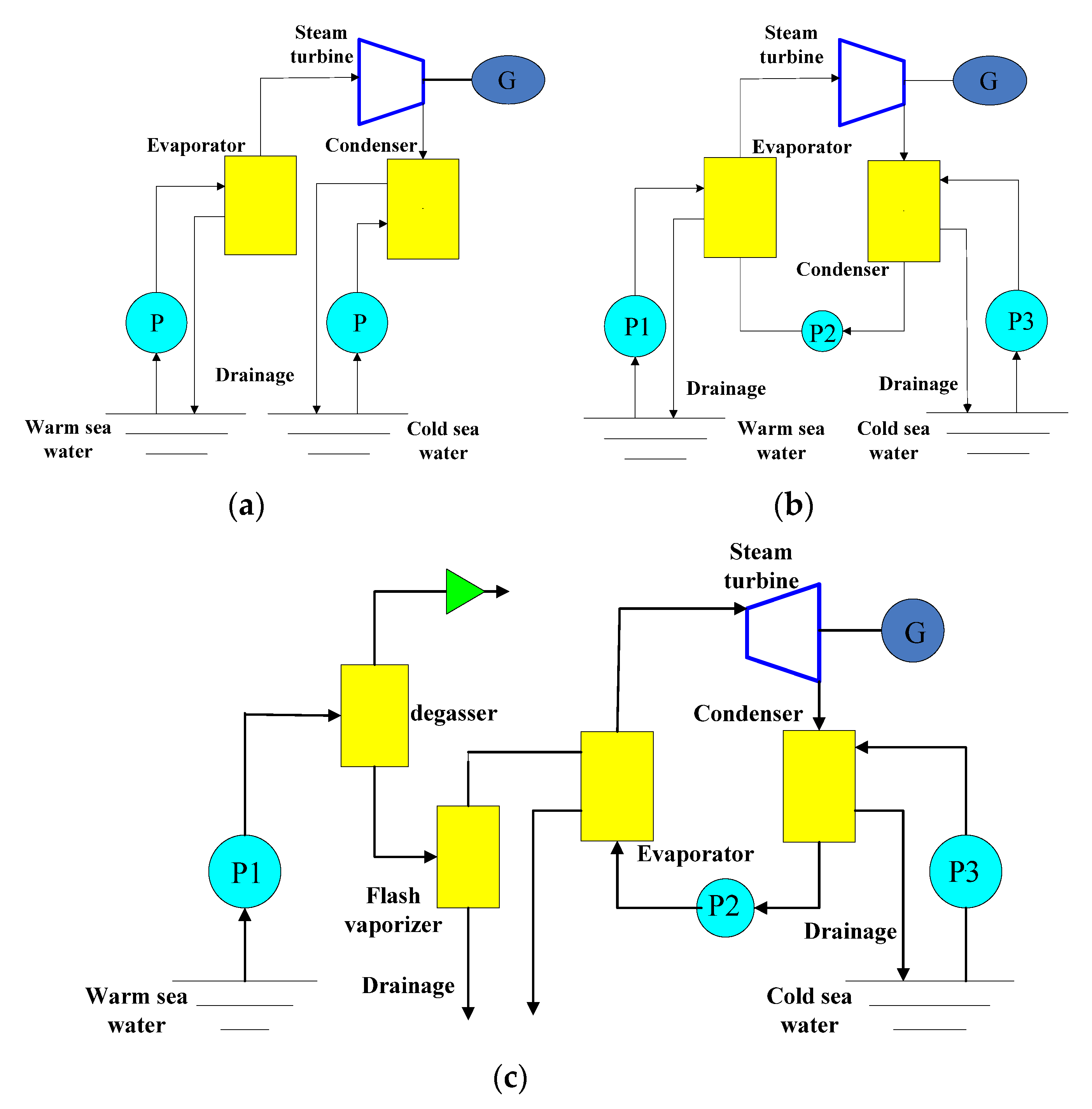
The ocean thermal energy is derived from solar energy and recognized by the international community as one of the most promising energy sources. According to the International Energy Agency, the installed capacity of offshore renewable energy could reach 750 GW by 2050 [74]. The by-products produced by ocean thermal energy conversion have no pollution to the environment, which are environmentally friendly energy [74,75]. The ocean thermal energy conversion (OTEC) technology is similar to the Karina cycle power generation technology. The operation of ocean thermoelectric power generation can be briefly divided into the following steps [75]: firstly, the warm water of the ocean surface is pumped to the normal temperature evaporator, and the ammonia is heated in an evaporator to evaporate to high-pressure gas. Second, the high-pressure gas is entered into the expander, which makes the expander rotate and drive the generator to generate electricity, while the high-pressure gas is changed into the low-pressure gas. Third, the cold water in the deep-water area is pumped into the condenser so that the low-pressure gas from the expander is condensed into liquid. At present, there are three main types of ocean thermal energy conversion: open cycle power generation system, closed cycle power generation system and hybrid cycle power generation system. The power generation principle is shown in Figure 16 [76]. The development and utilization of thermoelectric energy has a long history. So far, developed countries represented by the United States, Japan and France have carried out a lot of research work on the development and utilization of thermoelectric energy in the ocean, which is at the leading level in the world [77]. The development and utilization technology of thermoelectric energy in China is still in the principle research of thermoelectric energy generation device. Although some progress has been made in recent years, there is still a big gap compared with foreign countries.

3.2.3. Liquefied Natural Gas (LNG) Cold Energy Generation

There is a huge demand for LNG in China. According to the International Natural Gas Union (IGU), global LNG trade volume reached 316.5 million tons in 2018, with an average annual growth rate of 9.8% [78]. However, during the heating process, about 830 kJ/kg cooling capacity is wasted, so it is of great significance to recover the cold energy of LNG [79]. LNG cold energy generation is one of the main methods of LNG cold energy utilization. LNG cold energy power generation technology mainly includes direct expansion method, secondary media method, combined method, hybrid media generation method, Gas turbine utilization method, organic Rankine cycle method and Brayton cycle method [80,81,82]. Among them, direct expansion method and secondary media method although are of lower efficiency, but the principle simple, applicability, less restrictive conditions, and it are worth promoting. The operating principles of these two methods are shown in Figure 17 [82].
The reserves of solar energy, ocean thermal energy, and LNG cold energy are huge, but the utilization rate is extremely inefficient, so it has great potential for development and utilization. After decades of development, the low-temperature power generation technology has been relatively mature and has been a successful application to the solar energy, ocean thermal energy conversion and LNG power generation. The screw expander has a great advantage compared with the traditional steam turbine, which can be used to replace the turbo expander in the medium and low-temperature power generation system. Therefore, the screw expander will have great potential in the field of solar energy, ocean thermal energy conversion and LNG cold energy generation.

4. Conclusions

This paper mainly introduces the development and application of the screw expander. This paper classified, inducted and summarized the research status of the leakage, rotor geometry, manufacturing and lubrication that affect the performance of the screw expander.
As for the leakage problem of screw expander, some scholars make use of new theory (ICCAD/TCA) or adopt experimental methods to analyze and study it. With the development of computer application in recent years, many scholars have carried out analysis and research by using computer-aided design. For example, SCCAD software was used to study the leakage characteristics of the screw expander, and CFD simulation analysis was carried out based on the model established by PROE. Most studies on working medium leakage are based on single-phase gas or single-phase liquid analysis. In order to be close to the real working situation, many scholars conduct research and analysis by establishing models and making a series of assumptions about the working medium. The rotor profile directly determines the geometric parameters, which decide the size of the leakage, such as the leakage triangle and the contact line length, etc. Therefore, the rotor profile determines the performance of the screw expander to a large extent. Many scholars apply new methods, new thoughts and new tools for optimization and redesign of the rotor profile. Recently, computer technology is playing an important role in the optimization of the typical profile and the development of the new profile. The rotor profile is designed by using the ‘mutual engagement principle of Gear’ theory, SCCAD software, inverse design or other methods. Processing accuracy of the screw rotor has a significant influence on the leakage gap, seal, friction of the screw mechanism. The requirement of screw rotor for machining accuracy is high. With the development of the CNC machine technology, professional screw rotor processing equipment has successfully been developed, and corresponding new screw processing methods have been proposed, so the accuracy and performance of the screw rotors obtained the significant enhancement. The grinding method not only has high machining efficiency but also makes the rotor have a higher precision of tooth surface. The forming milling method can meet the requirements of both efficiency and machining accuracy and is the most common method of the manufacturing process of the rotor. The sealing component is a critical part of the screw expander, and it is also the vulnerable parts of the expander. The quality of the seal structure and seal directly affects the economy and reliability of the expander. At present, the main sealing methods of shaft end seal of screw mechanical are labyrinth seal, floating ring seal, mechanical seal, carbon ring seal, dry gas seal, etc. The thermodynamic model of the screw expander was established by mathematical model or experimental data. Geometric modelling is the foundation of the three-dimensional Computational Fluid Dynamics (CFD) analysis of screw expander, and computer-aided design could provide benefits for accurate identification of geometric parameters.
In addition, the paper also introduces the application of screw expander in the field such as residual pressure, industrial waste heat and renewable energy generation, and lists the corresponding typical examples. Finally, according to the structure and application characteristics of screw expander, a reasonable prediction is made of the potential applications of the screw expander. This paper can provide some reference for the research and development of screw expansion and make some contributions.

Author Contributions

Conceptualization, J.W. (Junying Wei) and J.W. (Jidai Wang); formal analysis, J.W. (Jihong Wang); investigation, Q.H.; resources, L.Y.; data curation, Z.J.; writing—original draft preparation, Q.H.; writing—review and editing, J.W. (Junying Wei); supervision, J.W. (Jidai Wang); All authors have read and agreed to the published version of the manuscript.

Funding

This work was supported by the Project of Science and Technology Research Program for Colleges and Universities in Shandong Province (J18KA049).

Acknowledgments

The authors would like to thank to the research grant support from the Project of Science and Technology Research Program for Colleges and Universities in Shandong Province.

Conflicts of Interest

The authors declare no conflict of interest.

Nomenclature

ORCOrganic Rankine Cycle
ICCDIso-clearance Contour Diagram
TCATooth Contact Analysis
ASRAverage-state Region
SCCADscrew rotor design and calculation software
PROEPro/Engineer
CFDComputational Fluid Dynamics
NURBSNon-Uniform Rational B-Splines
MFCMicrosoft Foundation Classes
OpenGLOpen Graphics Library
TSDTwin-screw compressor yin-yang rotor type line design system
CNCComputer Numerical Control
CBNCubic Boron Nitride
CAD/CAMComputer Aided Design/Computer Aided Manufacturing
MATLABMatrix&Laboratory
AutoLISPAutodesk List Processor
OTECOcean Thermal Energy Conversion
IGUInternational Natural Gas Union
LNGLiquefied Natural Gas

References

  1. Zhe, L.U. Analysis on Current Situation of Industrial Waste Heat Recovery in China. Equip. Manuf. Technol. 2019, 12, 204–206. [Google Scholar]
  2. Xiong, H. The Survey Report on Utilization of Industrial Waste Heat Resources. 2017. Available online: http://www.doc88.com/p-1788513706822.html (accessed on 13 December 2003).
  3. Fierro, J.J.; Escudero-Atehortúa, A.; Nieto-Londoño, C.; Giraldo, M.; Jouhara, H.; Wrobel, L.C. Evaluation of Waste Heat Recovery Technologies for the Cement Industry. Int. J. 2020, 100040. [Google Scholar] [CrossRef]
  4. Zhang, J.; Zhao, L.; Dong, H. Review of Research on Industrial Waste Heat Recovery Based on Organic Rankine Cycle. In Proceedings of the 10th National Energy and Thermal Engineering Academic Annual Conference, Hangzhou, Zhejiang Province, China, 14 August 2019; pp. 392–396. [Google Scholar]
  5. Dibazar, S.Y.; Salehi, G.; Davarpanah, A. Comparison of Exergy and Advanced Exergy Analysis in Three Different Organic Rankine Cycles. Processes 2020, 8, 586. [Google Scholar] [CrossRef]
  6. Feng, Y.-Q.; Wang, X.; Niaz, H.; Hung, T.-C.; He, Z.-X.; Zeb, A.J.; Xi, H. Experimental comparison of the performance of basic and regenerative organic Rankine cycles. Energy Convers. Manag. 2020, 223, 113459. [Google Scholar] [CrossRef]
  7. Ehyaei, M.A.; Ahmadi, A.; Rosen, M.A.; Davarpanah, A. Thermodynamic Optimization of a Geothermal Power Plant with a Genetic Algorithm in Two Stages. Processes 2020, 8, 1277. [Google Scholar] [CrossRef]
  8. Alizadeh, S.M.; Ghazanfari, A.; Ehyaei, M.A.; Ahmadi, A.; Jamali, D.H.; Nedaei, N.; Davarpanah, A. Investigation the Integration of Heliostat Solar Receiver to Gas and Combined Cycles by Energy, Exergy, and Economic Point of Views. Appl. Sci. 2020, 10, 5307. [Google Scholar] [CrossRef]
  9. Di Cairano, L.; Nader, W.B.; Nemer, M. Assessing fuel consumption reduction in Revercycle, a reversible mobile air conditioning/organic Rankine cycle system. Energy 2020, 118588. [Google Scholar] [CrossRef]
  10. Usman, M.; Imran, M.; Haglind, F.; Pesyridis, A.; Park, B.-S. Experimental analysis of a micro-scale organic Rankine cycle system retrofitted to operate in grid-connected mode. Appl. Eng. 2020, 180, 115889. [Google Scholar] [CrossRef]
  11. Jingwen, Y.; Kefeng, Y.; Jia, H.; Ganghui, L.; Hongbin, G. Research progress and application status of organic Rankine cycle expanders. Therm. Power Gener. 2019, 48, 10–18. [Google Scholar]
  12. Yajing, S. Flow Field Analysis and Dynamic Performance Study of Twin Screw Expander. Ph.D. Thesis, Yangzhou University, Yangzhou, China, April 2019. [Google Scholar]
  13. Yuan, T. Application of screw expander in waste heat power generation project. Energy Res. Util. 2018, 3, 54–55. [Google Scholar]
  14. Fong, Z.; Huang, F.; Fang, H. Evaluating the inter-lobe clearance of twin-screw compressor by the iso-clearance contour diagram (ICCD). Mech. Mach. Theory 2001, 36, 725–742. [Google Scholar] [CrossRef]
  15. Prins, J.; Ferreira, C.A.I. Leakage Experiments on a Running Twin Screw Compressor. Arzneim. Forsch. 2002, 25, 975–976. [Google Scholar]
  16. Tian, Y.; Lu, J.; Shen, J.; Wu, H.; Xing, Z. Optimization on shaft seals for a twin-screw steam compressor based on a novel uniform property region (UPR) model on discharge end-face. Int. J. Refrig. 2018, 91, 167–176. [Google Scholar] [CrossRef]
  17. Xing, Z.; Fu, P. Study of Leakage Characteristics in Twin Screw Compressor with Refrigerant R134a. Refrig. J. 2000, 04, 23–28. [Google Scholar]
  18. Qi, Y.; Yu, Y. Numerical simulation and analysis of leakage process in twin screw expander. J. Shanghai Jiaotong Univ. 2016, 504, 496–501. [Google Scholar]
  19. Papes, I.; Degroote, J.; Vierendeels, J. 3D CFD Analysis of an Oil Injected Twin Screw Expander. In Proceedings of the ASME 2013 International Mechanical Engineering Congress and Exposition, San Diego, CA, USA, 15–21 November 2013. [Google Scholar]
  20. Hesse, J.; Spillekohoff, A.; Shorbagy, A.E. CFD simulation of a screw compressor including leakage flows and rotor heating. In Proceedings of the 9th International Conference on Compressors and Their Systems, London, UK, 7–9 September 2015. [Google Scholar]
  21. Li, H.; Jin, G.; Wu, Z. Leakage analysis and calculation of oil injection single screw compressor. Fluid Mach. 1993, 8, 14–18. [Google Scholar]
  22. Wang, Z.; Liu, Z.; Wu, W.; Feng, Q. Research of leakage characteristics of single screw refrigeration compressors with the Multicolumn Envelope Meshing Pair. Int. J. Refrig. 2015, 49, 1–10. [Google Scholar] [CrossRef]
  23. Bein, T.W.; Hamilton, J.F. Computer Modeling of an Oil Flooded Single Screw Air Compressor. 1982. Available online: https://docs.lib.purdue.edu/cgi/viewcontent.cgi?article=1382&context=icec (accessed on 11 December 2020).
  24. Jiang, S.G. Study on the Positive and Negative Configurations of Twin Screw Rotor Profile Based on NURBS. Ph.D. Thesis, Jiangnan University, Wuxi, China, June 2018. [Google Scholar]
  25. Hui, L. Research and Simulation of MWorks Based Screw Compression Machine Line. Ph.D. Thesis, Huazhong University of Technology, Wuhan, China, January 2013. [Google Scholar]
  26. Zaytsev, D.; Ferreira, C.A.I. Profile generation method for twin screw compressor rotors based on the meshing line. Int. J. Refrig. 2005, 28, 744–755. [Google Scholar] [CrossRef]
  27. Stosic, N. Profile Rotors. Available online: http://www.staff.city.ac.uk/~sj376/nrot.html (accessed on 13 December 2017).
  28. Litvin, F.L.; Feng, P.H. Computerized design, generation, and simulation of meshing of rotors of screw compressor. Mech. Mach. Theory 1997, 32, 137–160. [Google Scholar] [CrossRef]
  29. Xueming, H.; Guojiang, S.; Meiping, W.; Rong, Z.; Xiaogang, J. Application of B-spline in Reverse Design Method of Screw Rotor Profiles. Mech. Sci. Technol. 2018, 37, 43–54. [Google Scholar]
  30. SCCAD. Screw Compressor Design and Calculation Software. Scientific and Technological Achievements; Xi’an Jiaotong University: Xi’an, China, 2002. [Google Scholar]
  31. Xueming, H.; Zhengang, J.; Meiping, W.; Rong, Z.; Xiaogang, J. Research on Relationship between Rotor Profiles and Meshing Lines in Twin-screw Compressors. China Mech. Eng. 2017, 28, 763–770. [Google Scholar]
  32. Chunyang, J. Research on the Design of Double Helix Rotor Profile and Cutter Blade Shape. Ph.D. Thesis, Zhongnan University, Changsha, China, June 2013. [Google Scholar]
  33. Shi, G.-J.; He, X.-M.; Zhang, R. Research on Development of the Design System of Twin Screw Compressor Rotor Profiles. Compress. Technol. 2018, 5, 6–13. [Google Scholar]
  34. Jie, Z. Study on Machining Method of Screw Rotor in Oil-Free Screw Vacuum Pump. Ph.D. Thesis, Northeastern University, Shenyang, Liaoning, China, June 2015. [Google Scholar]
  35. Jia, Z. Research on the Segmented Grinding Technology of Large Screw Rotor. Ph.D. Thesis, Shaanxi Institute of Technology, Hanzhong, China, June 2015. [Google Scholar]
  36. Wang, H. Research on Inner Helical Surface Milling Processing Technology of Screw Drilling Tool Motor Stator. Ph.D. Thesis, Shenyang University of Technology University, Shenyang, China, January 2012. [Google Scholar]
  37. Song, R. Numerical Simulation Method for Profile Calculation of Disk Milling Cutter for Screw Machining. Ph.D. Thesis, Dalian Jiaotong University, Dalian, China, June 2015. [Google Scholar]
  38. Wang, K. Research for Milling with Non-Instantaneous-Pole Envelope Theory Applying Technology of Complex and Abnormal Helical Surface. Ph.D. Thesis, Tianjin University, Tianjin, China, June 2003. [Google Scholar]
  39. Sheth, D.S.; Malkin, S. CAD/CAM for Geometry and Process Analysis of Helical Groove Machining. CIRP Ann. Manuf. Technol. 1990, 41, 225–228. [Google Scholar] [CrossRef]
  40. Shan, J.; Jiang, X. Computer aided design of form milling cutter for helicodal surface. J. Zhejiang Univ. Technol. 2000, S1, 38–40. [Google Scholar]
  41. Yuchun, K.; Shu, F.; Longmei, W.; Haitao, R. Numerical Simulation Method of Forming Grinding Wheel Contour for Complex Spiral Curved Surfaces. J. Sichuan Univ. 2013, 2, 182–187. [Google Scholar]
  42. Liang, D.; Li-Min, D.; Ze-Wei, W.; Rui, W.; Liang, Y. Solution of grinding wheel machining drill bit with spiral groove based on Matlab. Heavy Mach. 2019, 6, 69–75. [Google Scholar]
  43. Li, J.; He, W.; Gao, J. Simulation and verification of profile of milling cutter for forming compressor screw arbor. Tool Technol. 2007, 1, 72–74. [Google Scholar]
  44. Zhang, L.; Zhang, R.; Zhao, F. A New CAD Method to Generate Manufacturing Tool of Helicoids. Mech. Des. Res. 2011, 2, 83–86. [Google Scholar]
  45. Lee, Y.S. Rapid Design of Forming Milling Cutter for Screw of Compressor for Coal Mine. Coal Mine Mach. 2020, 41, 90–92. [Google Scholar]
  46. Jiang, L. Analysis of Dynamic Characteristics of Spiral Surface of Milling Rotor with Disk Milling Cutter. Ph.D. Thesis, Shenyang University of Technology, Shenyang, China, June 2019. [Google Scholar]
  47. Wang, G. Study on Error Control in Forming Grinding of Screw Rotor with Complex Section. Ph.D. Thesis, Shaanxi Institute of Technology, Hanzhong, China, June 2015. [Google Scholar]
  48. Zhao, Y.; Hou, H.; Li, Z.; Zhou, B.; Tian, G. Research on twin—Screw compressor rotor precision grinding method. Manuf. Technol. Mach. Tool 2014, 2, 28–32. [Google Scholar]
  49. Hou, H.; Zhao, Y. Accurate calculation of rotor grinding parameters of twin screw compressor. J. Mach. Des. 2014, 10, 72–76. [Google Scholar]
  50. Wang, K. Fluid-Solid Coupling Analysis of T-Groove Dry Gas Seal. Ph.D. Thesis, Anhui University of Science and Technology, Huainan, China, June 2018. [Google Scholar]
  51. Yin, Z. Application Study of the Day Gas Seal in the Gas Screw Compress of the Crude Distillation Units. Ph.D. Thesis, Beijing University of Technology, Beijing, China, May 2013. [Google Scholar]
  52. Zhou, W. The sealing structure of the screw compressor. Lubr. Eng. 1988, 3, 67–68. [Google Scholar]
  53. Smith, I.K.; Stošič, N.; Aldis, C.A. Development of the trilateral flash cycle system. Part 3: The design of high-efficiency two-phase screw expanders. J. Power Energy 1996, 210, 75–93. [Google Scholar] [CrossRef]
  54. Giuffrida, A. Improving the semi-empirical modelling of a single-screw expander for small organic Rankine cycles. Appl. Energy 2017, 193, 356–368. [Google Scholar] [CrossRef]
  55. Qi, Y.; Yu, Y.; Hooman, K. Thermodynamic Simulation on the Performance of Twin Screw Expander Applied in Geothermal Power Generation. Energies 2016, 9, 694. [Google Scholar] [CrossRef] [Green Version]
  56. Tang, H.; Wu, H.; Wang, X.; Xing, Z. Performance study of a twin-screw expander used in a geothermal organic rankine cycle power generator. Energy 2015, 90, 631–642. [Google Scholar] [CrossRef]
  57. Tian, Y.; Xing, Z.; He, Z.; Wu, H. Modeling and performance analysis of twin-screw steam expander under fluctuating operating conditions in steam pipeline pressure energy recovery applications. Energy 2017, 141, 692–701. [Google Scholar] [CrossRef]
  58. Guo, S.; Ying, Z.; Shi, B.; Zhu, Y.; Pan, L. Effect of inlet vent on screw expander efficiency. Sci. Technol. Innov. Her. 2015, 23, 1–4. [Google Scholar]
  59. Buckney, D.; Kovacevic, A.; Mujic, E.; Stosic, N. Some Aspects of Estimating Geometric Characteristics of Screw Compressors. In Proceedings of the International Compressor Engineering Conference, Purdue, IN, USA, 16–19 July 2012. [Google Scholar]
  60. Seshaiah, N.; Ghosh, S.K.; Sahoo, R.K.; Sarangi, S.K. Mathematical modeling of the working cycle of oil injected rotary twin screw compressor. Appl. Therm. Eng. 2006, 27, 145–155. [Google Scholar] [CrossRef] [Green Version]
  61. Papes, I.; Degroote, J.; Vierendeels, J. Development of a thermodynamic low order model for a twin screw expander with emphasis on pulsations in the inlet pipe. Appl. Therm. Eng. 2016, 103, 909–919. [Google Scholar] [CrossRef] [Green Version]
  62. Kovacevic, A.; Rane, S. 3D CFD analysis of a twin screw expander. In Proceedings of the 8th International Conference on Compressors and their Systems, San Diego, CA, USA, 9–10 September 2013; pp. 417–429. [Google Scholar]
  63. Nikolov, A.; Huck, C.; Brümmer, A. Influence of Thermal Deformation on the Characteristic Diagram of a Screw Expander in the Automotive Application of Exhaust Heat Recovery. In Proceedings of the International Compressor Engineering Conference, Purdue, IN, USA, 16–19 July 2012. [Google Scholar]
  64. Baidu Encyclopedia; “Screw Compressor” Baidu Encyclopedia Entry [EB/OL]. Available online: https://baike.so.com/doc/5734536-5947281.html (accessed on 8 July 2020).
  65. Kaishan Compressor Co. LTD. The Screw Swelling Machine Sends Electricity. [EB/OL]. Available online: http://www.kaishancomp.com/product.asp (accessed on 8 December 2019).
  66. Wenjuan, S.; Jiangxi Huadian Electric Power Co., Ltd. Has Successfully Developed the Summary of Screw Rod Expansion Power Machine. Available online: http://jxxy.jxnews.com.cn/system/2013/06/28/012490596.shtml (accessed on 8 December 2019).
  67. Yu, Y.; Hu, D.; Wu, F. Applications of the Screw Expander in Geothermal Power Generation in China. In Proceedings of the World Geothermal Congress 2015, Melbourne, Australia, 19–25 April 2015. [Google Scholar]
  68. Weng, Y. Conversion Process and Utilization of Low Grade Heat Energy; Xi’an Jiao Tong University Press: Xi’an, China, 2014; pp. 5–9. ISBN 978-7-313-12376-3. [Google Scholar]
  69. Chen, L. Performance Analysis and Matching Research of Expander for Solar Energy Multi-Feeder System. Ph.D. Thesis, North China Electric Power University, Beijing, China, March 2019. [Google Scholar]
  70. Iodice, P.; Langella, G.; Amoresano, A. Energy performance and numerical optimization of a screw expander–based solar thermal electricity system in a wide range of fluctuating operating conditions. Int. J. Energy Res. 2020, 44, 1858–1874. [Google Scholar] [CrossRef]
  71. Zhou, Y.; Lu, S.; Xie, K. Research of Organic Mediums Used in Rankin Cycle in Screw Expander. Chem. Equip. Pip. 2019, 56, 47–52. [Google Scholar]
  72. Zhang, Y.; Wu, Y.; Xia, G.; Ma, C.; Ji, W.; Liu, S.; Wang, J.; Guo, H. Performance Study on Single-screw Expander in Organic Rankine Cycle System. J. Mech. Eng. 2015, 51, 156–163. [Google Scholar] [CrossRef]
  73. Lanzhou da Cheng Screw Expansion Generator Solar Energy Collector Project. Available online: http://www.jxhdep.com/newsInfo.asp?id=284&pid=83 (accessed on 3 June 2020).
  74. Yin, L. Marine low-carbon Energy: A new Generation of Offshore Energy. High Technol. Ind. 2020, 9, 39–41. [Google Scholar]
  75. Wang, C.; Yee, A.; Tay, H.K.Z.Y. Research and developments on ocean thermal energy conversion. IES J. Part A Civ. Struct. Eng. 2011, 4, 41–52. [Google Scholar] [CrossRef]
  76. Feng, G.; Zhong, S. Research status and prospect of ocean thermal energy conversion. J. Northeast Electr. Power Univ. 2011, 31, 72–77. [Google Scholar]
  77. Juan, Y.; Ting, Y.; Da-Shu, L.I.; Zhi-Chuan, L. Study on the Up-to-Date Progress and Suggestions for Ocean Thermal Energy Conversion Technologies. J. Oceanogr. Technol. 2017, 4, 82–87. [Google Scholar]
  78. Kang, J.M. IGU World LNG Report 2019; Technical Report; International Gas Union (IGU): Vevey, Switzerland, 2019. [Google Scholar]
  79. Liu, Z.; Karimi Iftekhar, A.; He, T. A novel inlet air cooling system based on liquefied natural gas cold energy utilization for improving power plant performance. Energy Convers Manag. 2019, 187, 41–52. [Google Scholar] [CrossRef]
  80. Wu, X.; Cai, L.; Li, T.; Yang, X.; Yu, P. Latest progress of LNG cold energy utilization technology. Oil Gas Storage Transp. 2017, 36, 624–635. [Google Scholar]
  81. Zhang, L. Research on Waste Heat Recovery and Utilization System Based on LNG Cold Energy. Ph.D. Thesis, Liaoning University of Petroleum and Chemical Technology, Fushun, China, June 2019. [Google Scholar]
  82. Chen, L.; Xu, P.; Sun, L.; Dong, W.; Ma, K. Analysis on the current situation of LNG cold power generation technology. Nat. Gas Oil 2013, 6. Available online: https://www.semanticscholar.org/paper/Analysis-on-Current-Situation-of-LNG-Cold-Energy-Lng/f5e8c005dc2703a7fcca1cc88e630efc1196c7c1#citing-papers (accessed on 9 December 2020).
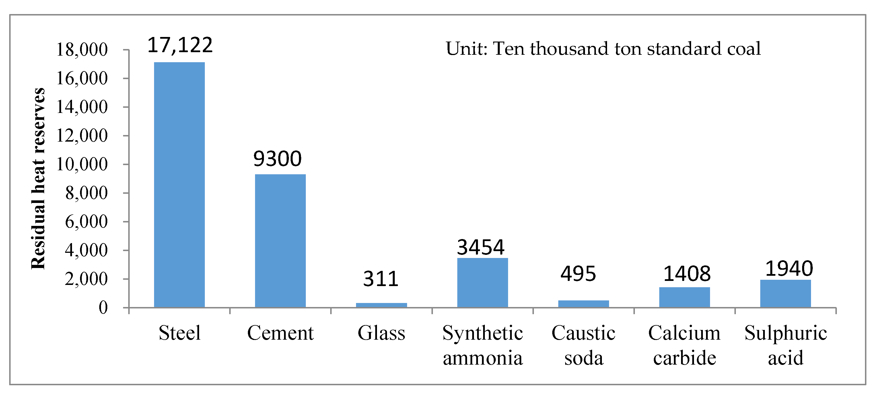
Figure 1. The amount of waste heat resources in seven industries.
Energies 13 06586 g001
Figure 2. Utilization of waste heat resources during 11th Five-Year.
Energies 13 06586 g002
Figure 3. The schematic diagram of the basic structure of screw expander.
Energies 13 06586 g003
Figure 4. The schematic diagram of operating principle of screw expander.
Energies 13 06586 g004
Figure 5. The schematic diagram of leakage channel.
Energies 13 06586 g005
Figure 6. The typical profiles of each stage of the development of the profile: (a) symmetrical circular arc profile; (b) unilateral asymmetrical cycloid; (c) GHH profile; (d) Hokuetsu profile.
Energies 13 06586 g006
Figure 7. Four seal systems of I-R company in the United States: (a) Standard labyrinth seal; (b) Labyrinth water ring seal; (c) Drive gas labyrinth seal; (d) Mechanical seal. 1. Oil throwing ring; 2. Bearing pedestal; 3 and 4. Fixed sealing liner; 5. Water ring; 6. Rotary seal groove; 7. Import of inert gas; 8. Sealing oil inlet; 9. Sealing chamber; 10. Spring; 11. Sealing ring; 12. Drive hoop; 13. Sealing sea.
Energies 13 06586 g007
Figure 8. The screw expanding power generator of Jiangsu Chengxing Phosphoru—Chemical Co. Ltd.
Energies 13 06586 g008
Figure 9. The screw expanding power generator of China petroleum and chemical corporation, Beijing Yanshan branch.
Energies 13 06586 g009
Figure 10. Alaska Chena hot spring geothermal generator set.
Energies 13 06586 g010
Figure 11. The 1MW screw expander generating unit in YangBaJing geothermal power plant.
Energies 13 06586 g011
Figure 12. The screw generator set in Yangyi Tibet, China.
Energies 13 06586 g012
Figure 13. The screw generator set of Buluan biomass power plant in the Philippines.
Energies 13 06586 g013
Figure 14. Solar-driven organic Rankine cycle power generation system diagram.
Energies 13 06586 g014
Figure 15. The screw expander generator set of Lanzhou.
Energies 13 06586 g015
Figure 16. The principle diagram of ocean temperature difference power generation system: (a) Open cycle power generation system; (b) closed cycle power generation system; (c) hybrid cycle power generation system.
Energies 13 06586 g016
Figure 17. Liquefied Natural Gas (LNG) power generation schematic diagram: (a) direct expansion method; (b) secondary media method.
Energies 13 06586 g017
Table 1. Status of industrial waste heat resources based on different industries.
IndustrySource of Waste Heat ResourcesPercentage of Fuel Consumption
MetallurgyRolling steel heating furnace, Soaking pit, Open hearth furnace, Blast furnaceabove 33%
ChemicalChemical reaction heat, Combustible chemical heat, etc.above 15%
Building materialHigh-temperature flue gas, Kiln crow cooling and high temperature products, etc.approx. 40%
GlassGlass melter, enameling furnace, pot furnace, etc.approx. 20%
PapermakingDrying cylinder, steamer, waste gas, black liquor, etc.approx. 15%
TextileDryer, slasher, digester, etc.approx. 15%
MachineryForged reheating furnace, cupola furnace, heat treatment furnace, etc.approx. 15%
Table 2. Comparison of advantages and disadvantages of various expansion machines.
TypePower Range/kWAdvantagesDisadvantages
velocity based (turbines) expandersRadial flow50–1000High isentropic efficiency;
Small losses of all kinds;
Compact structure;
Single stage expansion is relatively large;
Good sealing;
Manufacturing mature.
High speed;
Price is high;
Not suitable for small power units.
Axial flow>250In large units, the entropy efficiency is higher;
The power of the single machine can be maximized, and the expansion
ratio of the multistage expansion is also very large;
Long life.
The number of impellers is large and the manufacturing cost is high;
High maintenance cost;
The clearance loss and friction loss are larger in small units.
positive displacement (volumetric) expandersScroll expander1–20No valve, less moving parts;
Low speed;
Easy to manufacture;
The cost is low.
Lubrication system is required;
Small power;
The loss of power is large, mainly due to friction, suction and internal leakage.
Screw expander15–500Less moving parts, less loss;
High volume efficiency;
Suitable for two phase flow;
High flexibility;
Low speed.
Lubrication system is
required;
High machining accuracy requirement.
Slide expander1–10Suitable for two phase flow;
Simple structure;
Low speed.
Sealing problem;
Small power.
Piston expander20–100Suitable for two phase flow; Compared with other positive displacement expander, the expansion is higher;
Applicable to off-duty conditions; The cost is low.
Many moving parts, complex manufacturing, loss;
The weight is big, heavy; Flow resistance exists in inlet and outlet valves;
With other capacity, the
product expander is less efficient than the product expander.
Table 3. Main performance comparison of four Computer Numerical Control (CNC) grinding machines.
ProjectHOLROYD TG350EKLINGELNBERH H35RKAPP RJ59SK7032
Maximum mounting diameter/mm350350320320
Maximum spiral angle/(°)±60±60±60±60
The maximum stroke/mm1160660500/1000850
Grinding wheel spindle maximum speed/(r/min)3000360080002700
Maximum grinding wheel diameter/mm500500CNB500
Maximum workpiece weight500400 350
Degree of automationhighhighhighhigh
Automatic feeding of grinding wheel dressing++++
On-line measurement function+++
Compensation for tooth profile error compensation+++
Powerful grinding function+++
Table 4. Solar energy utilization and development forecast in major regions of the world. (unit: oil equivalent 106).
Year1990200020102020
Region
North America362485
Latin America12833
Western Europe12833
Russia and Eastern Europe12926
Middle East/North Africa23929
Sub-Saharan Africa12618
Pacific Ocean/China11623
Central Asia/South Asia131777
Total231464
Publisher’s Note: MDPI stays neutral with regard to jurisdictional claims in published maps and institutional affiliations.