Article

Analysis of a Battery Pack with a Phase Change Material for the Extreme Temperature Conditions of an Electrical Vehicle

1
Department of ICT Creative Design, Busan University of Foreign Studies, BUFS 66, Geumsaem-ro 486beon-gil, Geumjeong-gu, Busan 46234, Korea
2
Department of Robotics Eng, Busan University of Foreign Studies, 66, Geumsaem-ro 486beon-gil, Geumjeong-gu, Busan 46234, Korea
*
Author to whom correspondence should be addressed.
Energies 2020, 13(3), 507; https://doi.org/10.3390/en13030507
Submission received: 16 November 2019 / Revised: 27 December 2019 / Accepted: 10 January 2020 / Published: 21 January 2020
(This article belongs to the Section E: Electric Vehicles)

Abstract

:
Thermal management in an electric vehicle is important to extend the life of the battery. This paper is about modelling and analysis of a 6-kW battery module for improving the thermal performance of the lithium ion battery in electric vehicles with PCMs (phase change materials). For a battery thermal management system, we considered phase change materials such as RT15 (Rubitherm15), RT31, EG5 (Expanded Graphite5), and EG26 PCMs with different thermal properties. The ambient temperature conditions range considered was over 40 °C and below −10 °C, also tested on the hot and cool soaking conditions. The lithium polymer pouch single battery was designed and simulation analysis was performed with and without PCMs to enhance heat transfer rate. The simulation and experiment results on a single battery were satisfied to control the battery temperature within the safe operating conditions. Hence the proposed battery thermal management system (BTMS) was applied on a 6-kW battery pack. The design of the battery module was done in AUTOCAD and analysis was done in ANSYS CFD (computational fluid dynamics) software tool.

Graphical Abstract

1. Introduction

The demand of electric vehicles (EV) has increased, hence lithium batteries are used enormously, and in this situation enormous heat is also generated from the battery [1]. Batteries are very sensitive to frequent temperature changes and it affects battery life, hence it is important to design effective battery thermal management systems to enhance heat dissipation. Until now, many researchers developed various battery thermal management systems (BTMS) to meet the requirements such as high power, fast charging rates, and improved driving performance. These rapid changes of the batteries had to be monitored carefully and managed to avoid safety and thermal related issues. From the existing literature the BTMS had been broadly divided into two categories, they are active and passive cooling. The active cooling system is the forced circulation of air and water cooling systems [2]. Even air cooling can meet the requirement of vehicles during normal operating conditions, but battery temperature will be high with high charging and discharging conditions. The modified battery design such as such as changing the battery position, adding the guide plate, and entrance angle modification, but still this air cooling does not meet the requirements of electric vehicles [3,4]. The liquid or water cooling is better than the air cooling but includes complicated setup for circulation and that will increase the complexity and weight of the vehicle [5,6,7].
The PCM (phase change materials) cooling system is the best substitute for the above traditional thermal management methods [8,9,10]. The pump or blower is not required in this PCM cooling system, hence, it is cost effective and simple in design and construction. This PCMs cooling method is known as passive thermal management system. The excess heat generated by the battery of the electric vehicle can be absorbed by the PCMs close to the battery module. If the temperature of the battery reaches the PCM’s melting temperature, then heat will be stored in the form of latent heat and the temperature increase will be minimized.
PCMs undergo the phase change phenomenon by absorbing or releasing the abundant heat from the battery. This passive PCM cooling technology maintain the operating temperature of batteries at a relatively constant temperature range. In this way PCMs are the best solution for an effective thermal management system of an electric vehicle battery by maintaining a uniform temperature distribution even in any weather conditions. Zaho et al. [11] summarized different methods of thermal management system out of all those methods, concluding that PCMs are very effective technology for battery thermal management systems. Karimi et al. [12] experimentally studied on a cylindrical lithium ion battery thermal management system using composite PCMs and obtained the solution that metal matrix-PCM composites decreases the maximum ΔT between the battery surface and composite PCM up to 70%. Azizi and Sadrameli [13] proposed a thermal management system for a LiFePO4 battery pack with composite PCM and aluminum wire mesh plates and found the maximum temperature of the battery surface had been reduced by 19%, 21%, and 26% at 1C, 2C, and 3C discharge rates. 1C means the battery will discharge completely in 1 h, similarly, 2C means the battery will discharge completely in 2 h and vice-versa. Organic PCMs are widely used due to significant advantages such as high latent heat, high melting point range, effective thermal performance, adaptable molding during phase change, low corrosion, nontoxic, inflammable, and low cost. Moreover, low thermal conductivity restricts the use of PCM based thermal management systems in required applications [14].
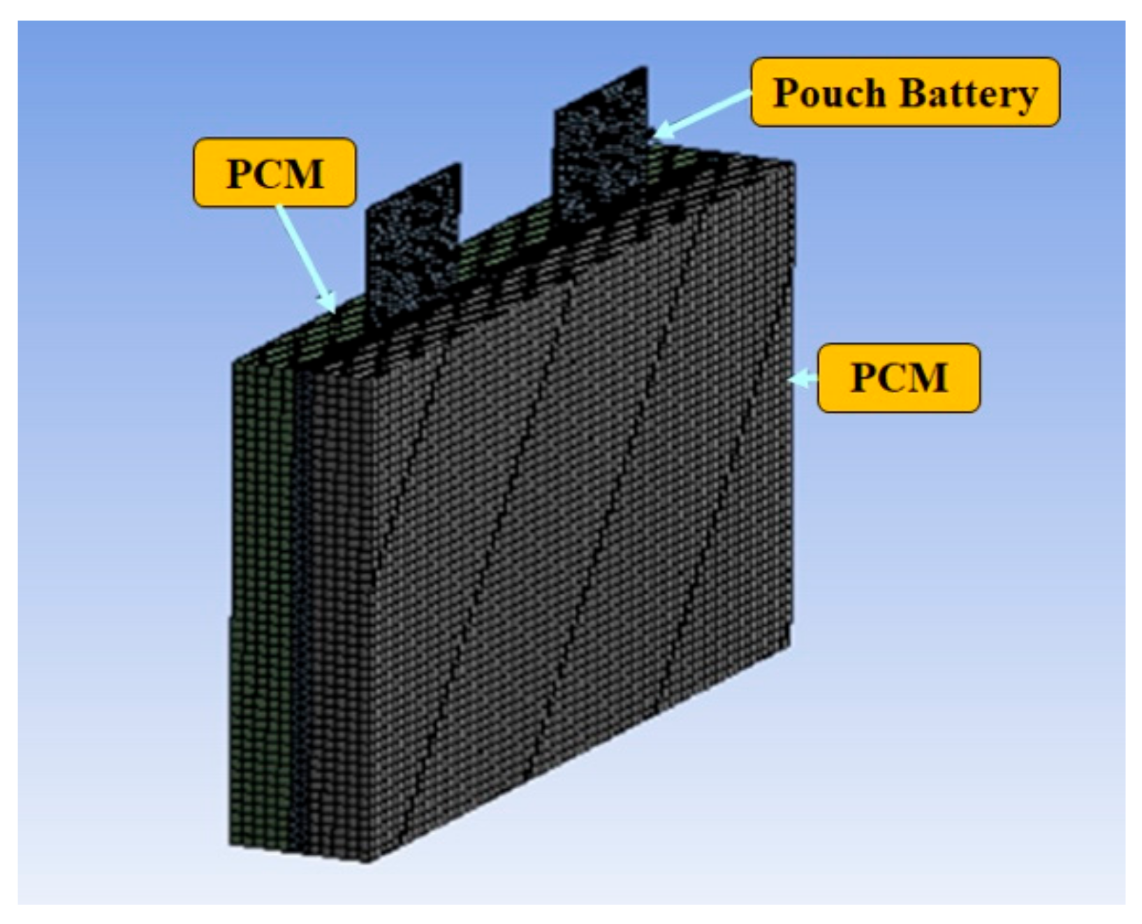
In the present paper, design and simulation of 6 kW battery pack was carried out based on the previous experimental and simulation results on a single lithium polymer pouch battery. The experiment and simulation showed that expanded graphite phase change material is the best PCM due to enhanced thermal properties to control the battery temperature within the safe operating temperatures. Important parameters that were considered to support expanded graphite PCM as the best PCM are due to its thermal conductivity, heat energy storage capacity, liquid leakage, and mass of PCM that effects the heat transfer rate. Liquid leakage was also tested in this experiment. Hence, from the experiment, we observed that during the energy storage process, no leakage was observed in the expanded graphite PCM and leakage was observed in the non-expanded graphite materials like RT15, RT31. The mass of PCM required to enhance heat transfer rate was also considered in this experiment.
From previous literature study, expanded graphite materials with high thermal conductivities and melting points were selected and show enhancement of heat transfer in the thermal management system of lithium batteries of electric vehicle. The key parameters for selection of a proper PCM for passive BTMS, depend not only thermal conductivity but also melting point of PCM is very crucial. At the same time, high melting points over the operating range are also not preferred because beyond melting point PCM acts as an insulating material which is not useful. The important parameters considered while selecting the PCMs are listed below [15]:
  • High thermal conductivity and high specific heat.
  • Melting point in the desired operating range.
  • Less or no sub cooling during freezing.
  • Volume changes are negligible during solidifying or during melting.
  • Non-poisonous, non-flammable, non-explosive, and should be stable.
  • Low cost and should be available in large quantities.
The RT44HC/EG PCM in [16], has a high thermal conductivity of 7.85 W/m K, the battery temperature reached 46.3 °C without PCM, but with PCM the battery temperature was controlled up to 36.3 °C, and hence the maximum temperature difference obtained was ΔT is 7.0 °C. From the result in [17], with PCMs of thermal conductivity range from 1 to 3 W/m K, there is good decrease in the temperature observed as ΔT is 6.7 °C, but if thermal conductivities increased from 7 to 15 W/m K, they observed no significant changes in temperature drop, only temperature change of 0.31–0.66 °C is seen.
Hence in this research we selected expanded graphite materials with low melting points between the range of 5–26 °C for better results. This expanded graphite PCMs we selected were firstly used for BTMS. The specific objectives are shown below:
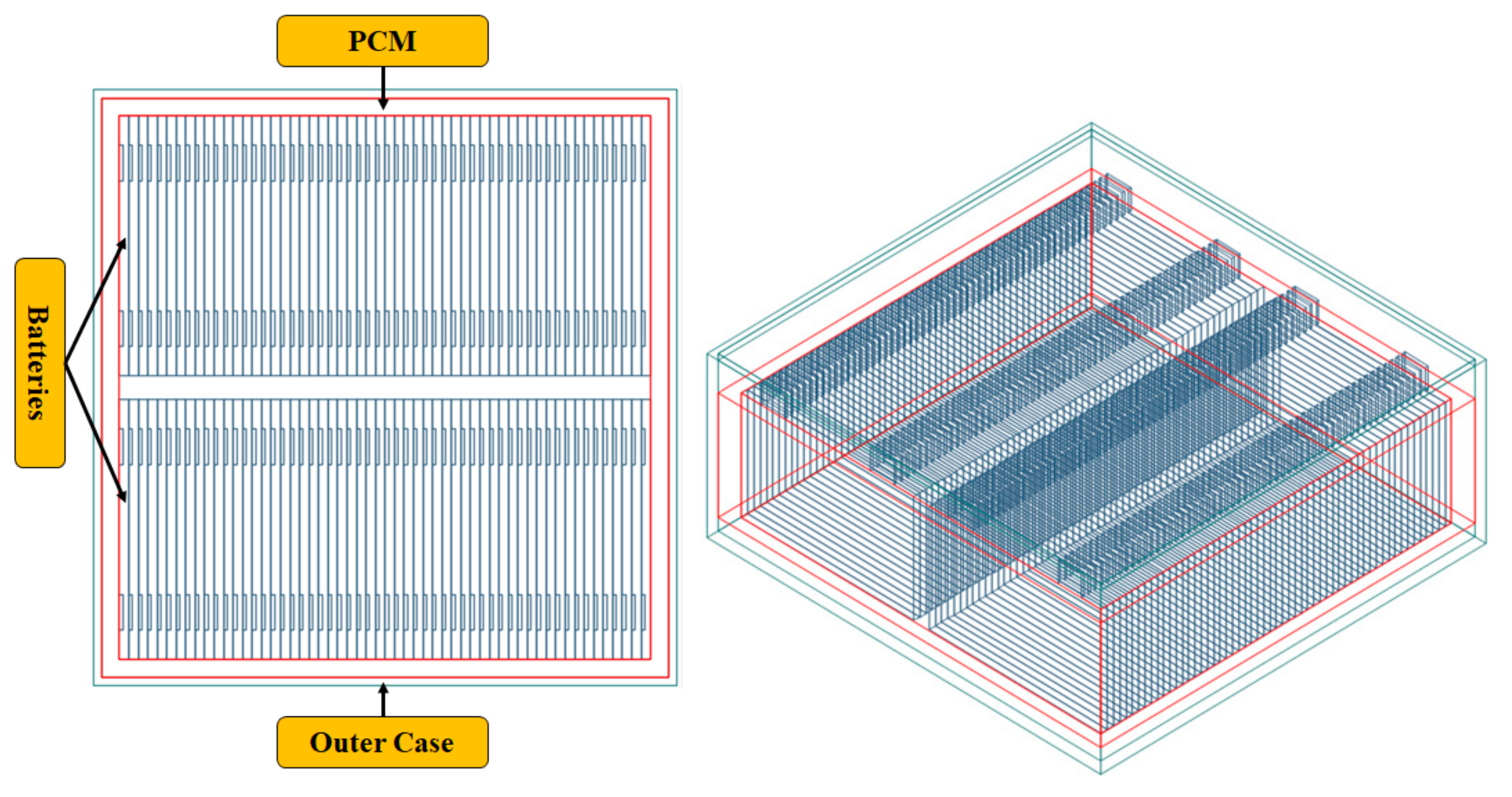
  • Design and propose the 6-kW Li polymer pouch battery with a PCM thermal management system based on single battery experimental results.
  • Maintain the battery temperature in the safe operating condition.
  • Simulate the proposed model of the battery module with different PCMS.
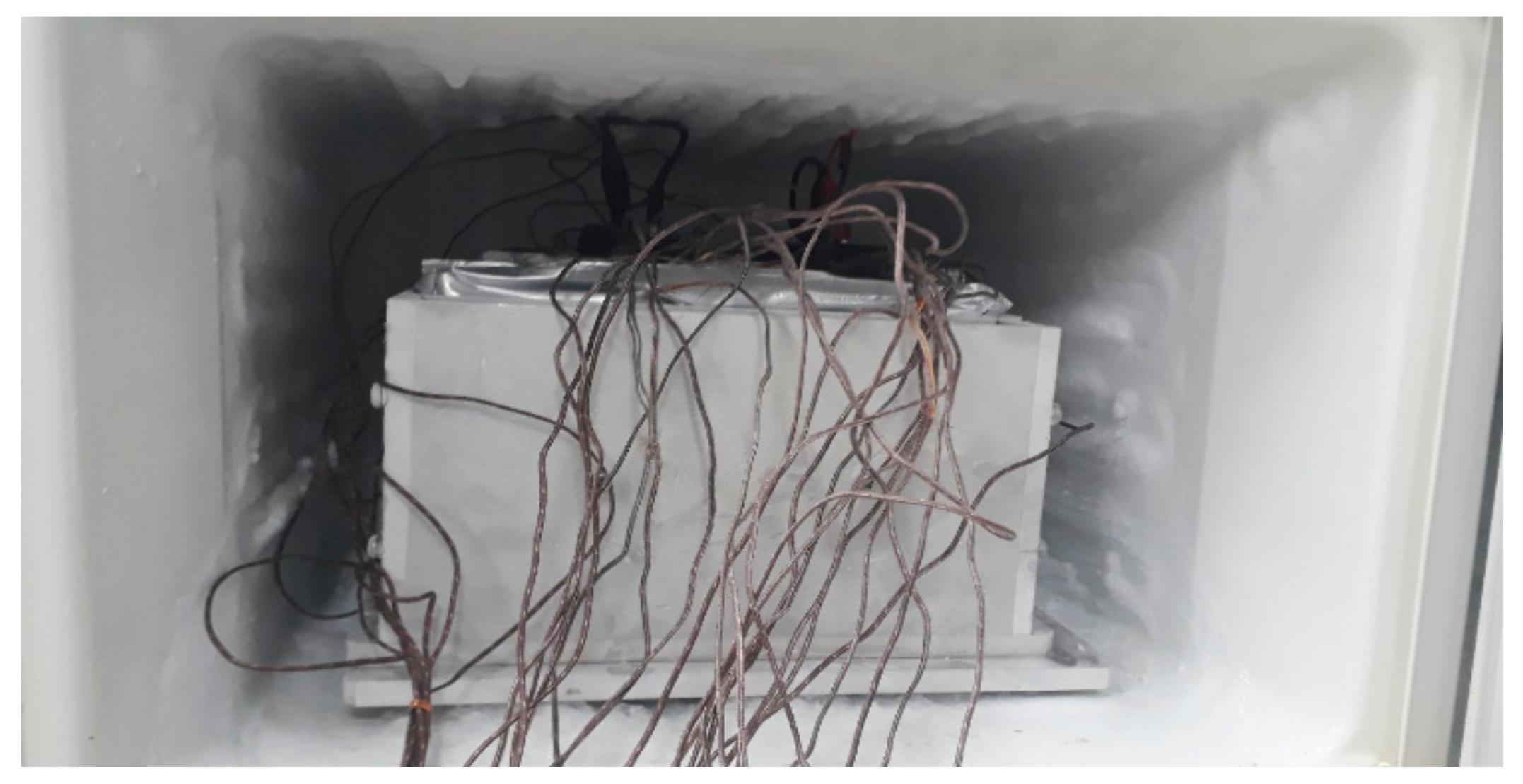
  • With the simulation result, realize the experiment setup for cold and hot soaking and run the experiment with proposed PCMs at different temperatures of the battery.
  • Compare results and identify the best PCM that satisfies the design specifications and maintains the battery under same operating temperature limits.
  • Apply the best PCM on the proposed 6-kW battery pack.

2. Design of Li Polymer Battery Module

2.1. Proposed Single Pouch Battery

Initially, the design of single pouch battery was completed and it was made of lithium polymer material with dimensions of 220 × 132 × 7.8 mm (width, length, and thickness) with rated capacity of each battery as 3.7 V/16 Ah. Thermocouples were placed on the battery to monitor the temperature every time. Four batteries were electrically connected in series. The modelling of proposed single lithium polymer pouch battery module for thermal management system is shown in Figure 1. The specifications of proposed model are given in Table 1.
Figure 2 shows the temperature point representation of the battery and PCM. T1 and T2 are the thermocouple sensors attached on the front side of the battery. T3 and T4 are the back side temperature representation, and T5, T6, T7, and T8 are the temperature points of the PCM.

2.2. Hot Soaking Test of the Proposed Battery

The proposed pouch battery module was maintained at a constant temperature of 40–60 °C, known as hot soaking. Hot soaking was done for 4 h to make all battery modules at a thermal equilibrium of specified temperature. The schematic representation for test setup is shown in Figure 3. During hot soaking, the experiment was conducted with PCM and also the battery temperature compared without PCM.

2.3. Cool Soaking Test of the Proposed Battery

The proposed pouch battery module was maintained at a constant temperature of −18 to −20 °C, known as cold soaking. Cold soaking was done for 8 h to make all battery modules at a thermal equilibrium of the specified temperature. The working principle of the PCM during hot and cool soaking is shown in Figure 4.
Cold soaking performance was done by ghadbeigi in their research, they found the performance of PCMs with cold soaking of 4 h [18]. We observed that during hot and cool soakings with PCM around the battery, the battery shows slow temperature changes with PCMs but without PCM the battery responds very quickly.

2.4. Design of Li Polymer 6-kW Battery Pack

We designed and proposed a model to improve life of the battery, and Figure 5 shows the design of the proposed 6 kW Lithium polymer battery module with specifications of 311.2 × 162.4 mm width and height, respectively, as given in Table 2. The battery module consists of 56 in series and two in parallel. The modelling of proposed battery is shown in Figure 6. The PCMs selected for this proposed model are attached to the battery pack indicated with green color.

3. Analysis of Heat Transfer in the Designed Battery

3.1. Heat Generation

The mode of heat transfer is free convection. The module was subjected to conjugate heat transfer. The generated heat was transferred to the room temperature at 26 °C. The internal battery surfaces and other components were coupled with the boundary conditions that satisfy the continuity of temperature profiles at the boundary line. This coupling was applied for both terminals of the battery module. The thermo physical properties of proposed PCMs are given in the Table 3.
For simulation purposes, the following assumptions were given:
(i)
Initial conditions were considered in the steady state.
(ii)
Batteries exhibit constant thermal conductivity.
(iii)
Terminals of batteries are exposed to the atmosphere and considered as free convection.
(iv)
Average specific heat is considered in simulation.
(v)
Radiation and contact resistances are negligible.
In the present work, the only heat generation component is the battery, that depends on discharge rate. The transient analysis was considered for the heat generation in the battery, the volumetric reversible and irreversible heat effects were considered. The general energy balance equation was considered. Hence, in this way, an average heat capacity was assumed for the battery [19]. The energy balance equation for the heat generation is as follows:
q = I u v T d u d t = h s A T m T a m b + M p c m C p c m T p c m T m + M c e l l C p c e l l d T d t ,
where I is the battery operating current. u and v are open circuit potential and battery operating potential; T is the battery operating temperature, Cp is the specific heat of the battery, hs is the heat transfer coefficient, A is the area of the battery, Tm is the melting temperature of PCM and Tamb is the ambient temperature of the battery, Mcell is the mass of battery. The governing equation is the sum of Gibbs free energy, electric work, and also entropy generation as follows,
Q = ΔG + Wele + TΔs,
where G is the Gibbs free energy, Wele is the electric work, and s is the entropy.
The heat generation equation is given in Equation (3), and we can also determine,
Q = m CpΔT,
where m is the mass of PCM.

3.2. The Finite Volume Method

The commonly used method in CFD (computational fluid dynamics) is the finite volume method, that was used to discretize the governing equation. The partial differential Equation (4) consists of a transient term, diffusion term, and a source term as below,
x ρ θ + ρ u θ Γ θ θ = s θ ,
where ρ is density of the battery, θ is 1 and h, for the energy and continuity equations respectively, Γθ is the diffusion coefficient and sθ is the source term. These terms will have their consistent units. According to the experiment setup the PCM melted zone is defined and restricted by the battery surface and there is no flow circulation in the domain. Only local melting is pool is observed. The thermal energy equation is analyzed and discretized as follows and the equation is assumed and considered only in two dimensions, that is in x and y directions.
t ρ c p T + x ρ u c p T + y ρ v c p T = x k T x + y k T y + s h .
The design was done in the ANSYS Fluent 16.0 version. The meshing nodes and elements were 63,669 and 80,632, respectively, and second order upwind solver was used. The finite volume based method solves the governing differential equations by integrating each control volume in the domain. The parameter temperature which is variable is interpolated between centroids of the calculated domain. The upwind scheme solver is applied to the discretized equations and the solution converged with different numerical techniques.
The energy equation is solved separately for both liquid and solid phases. An enthalpy-porosity technique was applied here to avoid the repeating of solution for both phases. This method consists of liquid fraction only in the portion of the battery in liquid state and not tracking the melting interface in the mushy zone. In order to find the temperature, the source term in the governing energy equation includes the amount of latent heat that was absorbed during the phase change process in the control volume. The source term, is defined as below,
s h = ρ β H t ,
where β is liquid fraction of PCM. The value of β = 1, if Tpcm > Tm and β = 0, if Tpcm < Tm.
For the entire battery zone, which is volumetric heat source is constant. However, in the phase change material it is zero because there is no heat generation instead only melting and solidifying. The viscosity of the solid zone is increased to exhibit the porous medium behavior in the mushy zones. When the battery is in the solid state the velocity is neglected from the algorithm and hence the velocity in the momentum equation will be removed. Hence the liquid fraction will be calculated with the iterations.
The linear source term and linear liquid fraction term were assumed for the melting or solidification interface. It gives the effective porosity of 0.6. To obtain this output the liquid fraction can be expressed as follows,
Δ h = h r e f + T r e f T c p d T .
The liquid fraction can become zero or 1, based on the temperatures greater or smaller than the melting temperature.

4. Simulation of Battery Module

4.1. Analysis of Pouch Battery Simulation and Experiment Results

The simulation conditions were initially: battery temperature at 26.1 °C and room temperature at 26 °C. When the battery was subjected to discharge for 30 min, then temperature of the battery reached to 3 °C without PCM. After applying load temperature contours were observed (Figure 7). By applying the transient analysis on the battery the simulation results were as shown in Figure 7a–e, with the temperature contours on a single pouch battery surface.
The experiment set up to conduct hot soaking experiment was shown in Figure 8. Test section consists of four batteries surrounded with four different PCMs exposed to heater that all this set up was enclosed in a chamber to maintain thermal equilibrium. Thermal sensors such as thermocouples were attached on each battery and PCMs to monitor the temperature changes. After attaining the required temperature at 45 °C start discharging of battery and observed the temperature change on battery with and without PCMs. The same procedure was repeated at temperature −18 °C, known as cool soaking, for cool soaking and to conduct the experiment the set up was shown in Figure 9. The only difference in hot soaking and cool soaking experiment set up was hot chamber and cool chamber.
The experimental results successfully satisfied the design specifications and controlled the battery temperature under safe operating conditions. In Figure 10a, the maximum temperature of the battery surface reached 35.9 °C during discharge at different load conditions without PCM. EG26 in the experimental result is 30.5 °C and ΔTmax is 5.4 °C which declined due to high thermal properties and hence we recommend EG26 as the best phase change material in battery thermal management system.
From Figure 10b, during hot soaking, the temperature of the battery was 45 °C without PCM within 2 h. By incorporating the PCM around the Li polymer pouch battery, there is slow temperature rise observed in the battery. With expanded graphite PCM after 4 h, the battery temperature is 43 °C, ΔT decreased by 2 °C with expanded graphite PCM. However, with other PCMs the rise in temperature is observed at the second hour.
From Figure 10c, the battery setup is initially maintained at room temperature and then placed in the cool chamber where temperature is maintained at −18 °C in the chamber and then warm up conditions of batteries were observed with different PCMs for 8 h. With the experiment, during cool soaking of battery quick response to coolness is observed. However, after incorporating the PCMs around the Li polymer pouch battery temperature after 180 s the temperature of the battery is 17 °C. Additionally, it was sloping down towards −20 °C after 7 h. Hence temperature of the battery module with PCM dropped much slower compared with the module without PCM. This reflects a good result of electric vehicles in cold weather because the system is maintained for a longer time at an optimal temperature.

4.2. Simulation of 6-kW Battery Module

Based on the results of experiment and simulation, that were conducted on a Li polymer pouch single battery, in this paper we proposed a model of a 6-kW lithium polymer pouch battery module. To design effective thermal management system of battery, it is essential to determine temperature analysis and heat load under normal conditions. The simulation conditions on the proposed battery were temperature of battery at 25 °C, room temperature maintained at 25.1 °C, and during load or charging conditions the temperature is increased up to 36.5 °C. For this, the heat capacity of a battery must be known. The design of battery module depends on important parameters such as complexity level of the system, application, and must be cost effective. These parameters were used in the simulation of the proposed module to observe the performance of the PCMs.
The important steps to follow with the thermal management system are as follows:
  • The first step is to define the design and limits of the battery thermal management system. In this context we considered battery shape, maximum and minimum temperature values.
  • By analyzing and testing, the heat generation and heat capacity of the battery were obtained. This analysis results in the effect of cooling or heating rate of the battery due to temperature.
  • With the results of analysis and tests, the thermal management system to be installed was determined according to the results obtained. For this we undertook the initial analysis to determine the condition of the module in short duration and stagnant air. High heat transfer coefficient material is recommended.
  • The detailed distribution of temperature in the system was done with the analysis.
  • Hence to find the risky areas, the prototype thermal management system is preferred.
  • Battery design optimization is possible with the results obtained.
The simulation shown in Figure 11 represents the temperature contours on the proposed 6-kW battery module with and without PCMs. In Figure 11a, the battery without PCM yields high temperature when compared to PCMS. In Figure 11d,e, the expanded graphite PCMs yields the lower temperature on the battery when compared to other commercial PCMs as in Figure 11b,c.

5. Results and Discussion

From analysis result, we conducted experiments with the proposed PCMs on the single pouch battery. The initial battery temperature is 26.1 °C before starting the discharge, the initial voltage of the battery is 14 V and for 1C, 1/2C and 1/4 battery discharge rates. During this condition the battery temperature was raised without PCM up to 35.9 °C, whereas with PCMs the temperatures were controlled to 32.6, 31.3, 30.6, and 30.7 °C for RT16, RT31, EG26, and EG6, respectively. From this experimental result, we observed expanded graphite PCMs are controlling the temperature below 30.5 °C when compared to other PCMs. Thermal performance of the proposed PCMs during experiment and simulation on single lithium polymer pouch battery is given in Table 4.
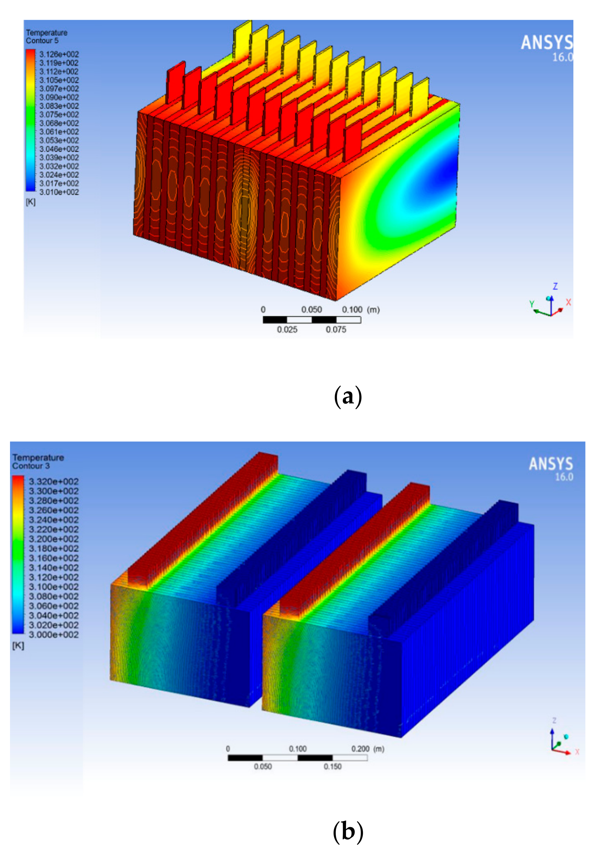
The analysis results show battery temperature with expanded graphite PCM shows less temperature contours, whereas without PCM around the battery yields a greater temperature than with PCM. In future we will analyze the thermal management system of 6 kW with hybrid cooling of PCM with air cooling and water cooling.
The mass of PCM required to store thermal energy is given as in Equation (3), and Table 5 gives the heat transfer rate with PCM mass of 1000 gm. In addition, from the obtained result it is observed that maximum heat transfer rate is observed with expanded graphite PCM and least heat transfer rate is with the battery without PCM. To improve heat transfer rate in other batteries such as 1, 2, and 5 the quantity of PCM required also increased 4.2, 2.5, and 8.8 times when compared with expanded graphite PCMs. The maximum temperatures in the 6-kW battery module with selected PCMs is shown in Table 6, from the analysis result battery maximum temperature during discharge without PCMs reached 36.5 °C, whereas with PCMs temperature can be maintained at 30.0 °C, meaning that ΔTmax is observed as 6.5 °C.

6. Conclusions

The analysis was done on the single pouch battery and after identifying the best PCM to control the temperature within the safe operating condition. The experiment was conducted with the single pouch battery analysis results. Commercial PCMs were selected for this purpose. Expanded graphite due to high thermal conductivity enhances heat transfer. From the above work, the following points are concluded:
  • The simulation and experimental results of the proposed thermal analysis on the single pouch battery given satisfactory results.
  • The experiment was carried out at room temperature of 26 °C and battery temperature was maintained at 26.1 °C before discharging. During high discharge rates up to 25 min, the battery temperature was observed as 35.9 °C without PCM, with PCM temperature on the battery during discharge it was nearly 28 °C.
  • Hot and cold soakings of the battery realize the exact temperature conditions of the battery at various temperatures.
  • With expanded graphite PCM, the battery has a delayed response according to the various temperatures, it takes nearly 8 h for cold soaking and 4 h for hot soaking with PCM.
  • Without PCMs, for complete hot soaking and cool soaking it takes nearly 2 h.
  • The expanded graphite was identified as the best phase change material that will enhance the heat transfer rateincreased upto 16.4% when compared to the model without PCM.
  • With the above result, a 6-kW lithium ion battery was proposed and with the simulation analysis the expanded graphite yielded an optimum result when compared with the remaining PCMS.
  • Finally, the battery with PCMs gives good result when compared to battery without PCM, also expanded graphite with high thermal conductivity is preferred for various environmental conditions, that will improve the battery performance with less voltage drop.

Author Contributions

Conceptualization, K.J.S.; methodology; K.J.S.; formal analysis, T.T. and K.J.S.; investigation, T.T. and T.H.K.; resources, T.T. and K.J.S.; writing—original draft preparation, T.T. and K.J.S.; visualization, K.J.S.; supervision, K.J.S.; project administration. All authors have read and agreed to the published version of the manuscript.

Funding

This work supports by the KOREA Ministry of Trade, Industrial and Energy. We had established the project, which is “The Development of High Strength Lightweight Aluminum Battery Package and PCM-BTMS for High Safety and Battery Efficiency Improvement of Electrical Vehicle 2020”.

Acknowledgments

This work supports by the KOREA Ministry of Trade, Industrial and Energy. We had established the project, which is “The Development of High Strength Lightweight Aluminum Battery Package and PCM-BTMS for High Safety and Battery Efficiency Improvement of Electrical Vehicle 2020”.

Conflicts of Interest

The authors declare no conflicts.

References

  1. Panchal, S.; Dincer, I.; Agelin-Chaab, M.; Fraser, R.; Fowler, M. Transient electrochemical heat transfer modeling and experimental validation of a large sized LiFePO4/graphite battery. Int. J. Heat Mass Transf. 2017, 109, 1239–1261. [Google Scholar] [CrossRef]
  2. Feng, X.; Fang, M.; He, X.; Ouyang, M.; Lu, L.; Wang, H.; Zhang, M. Thermal runaway features of large format prismatic lithium ion battery using extended volume accelerating rate calorimetry. J. Power Sources 2014, 266, 294–301. [Google Scholar] [CrossRef]
  3. Park, H. A design of air flow configuration for cooling lithium ion battery in hybrid electric vehicles. J. Power Sources 2013, 239, 30–36. [Google Scholar] [CrossRef]
  4. Park, S.; Jung, D. Battery cell arrangement and heat transfer fluid effects on the parasitic power consumption and the cell temperature distribution in a hybrid electric vehicle. J. Power Sources 2013, 227, 191–198. [Google Scholar] [CrossRef]
  5. Yang, X.-H.; Tan, S.-C.; Liu, J. Thermal management of Li-ion battery with liquid metal. Energy Convers. Manag. 2016, 117, 677–686. [Google Scholar] [CrossRef]
  6. Fang, G.; Huang, Y.; Yuan, W.; Yang, Y.; Tang, Y.; Ju, W.; Chu, F.; Zhao, Z. Thermal management for a tube–shell Li-ion battery pack using water evaporation coupled with forced air cooling. RSC Adv. 2019, 9, 9951–9961. [Google Scholar] [CrossRef] [Green Version]
  7. Ye, B.; Rubel, R.H.; Li, H. Design and Optimization of Cooling Plate for Battery Module of an Electric Vehicle. Appl. Sci. 2019, 9, 754. [Google Scholar] [CrossRef] [Green Version]
  8. Alrashdan, A.; Mayyas, A.T.; Al-Hallaj, S. Thermo-mechanical behaviors of the expanded graphite-phase change material matrix used for thermal management of Li-ion battery packs. J. Mater. Process. Technol. 2010, 210, 174–179. [Google Scholar] [CrossRef]
  9. Wu, W.; Zhang, G.; Ke, X.; Yang, X.; Wang, Z.; Liu, C. Preparation and thermal conductivity enhancement of composite phase change materials for electronic thermal management. Energy Convers. Manag. 2016, 101, 278–284. [Google Scholar] [CrossRef]
  10. Nomura, T.; Zhu, C.; Nan, S.; Tabuchi, K.; Wang, S.; Akiyama, T. High thermal conductivity phase change composite with a metal-stabilized carbon-fiber network. Appl. Energy 2016, 179, 1–6. [Google Scholar] [CrossRef] [Green Version]
  11. Zhao, Y.; Zou, B.; Li, C.; Ding, Y. Active cooling based battery thermal management using composite phase change materials. Energy Procedia 2019, 168, 4933–4940. [Google Scholar] [CrossRef]
  12. Karimi, G.; Azizi, M.; Babapoor, A. Experimental study of a cylindrical lithium ion battery thermal management using phase change material composites. J. Energy Storage 2016, 8, 168–174. [Google Scholar] [CrossRef]
  13. Azizi, Y.; Sadrameli, S. Thermal management of a LiFePO4 battery pack at high temperature environment using a composite of phase change materials and aluminum wire mesh plates. Energy Convers. Manag. 2016, 128, 294–302. [Google Scholar] [CrossRef]
  14. Zhang, J.; Li, X.; He, F.; He, J.; Zhong, Z.; Zhang, G. Experimental Investigation on Thermal Management of Electric Vehicle Battery Module with Paraffin/Expanded Graphite Composite Phase Change Material. Int. J. Photo Energy 2017, 2929473. [Google Scholar] [CrossRef] [Green Version]
  15. Rao, Z.; Wang, S. A review of power battery thermal energy management. Renew. Sustain. Energy Rev. 2011, 15, 4554–4571. [Google Scholar] [CrossRef]
  16. Ling, Z.; Wang, F.; Fang, X.; Gao, X.; Zhang, Z. A hybrid thermal management system for lithium ion batteries combining phase change materials with forced-air cooling. Appl. Energy 2015, 148, 403–409. [Google Scholar] [CrossRef] [Green Version]
  17. Huang, R.; Li, Z.; Hong, W.; Wu, Q.; Yu, X. Experimental and numerical study of PCM thermophysical parameters on lithium-ion battery thermal management. Energy Rep. 2019. [Google Scholar] [CrossRef]
  18. Ghadbeigi, L.; Day, B.; Lundgren, K.; Sparks, T.D. Cold temperature performance of phase change material based battery thermal management systems. Energy Rep. 2018, 4, 303–307. [Google Scholar] [CrossRef]
  19. Javani, N.; Dincer, I.; Naterer, G.; Yilbas, B. Heat transfer and thermal management with PCMs in a Li-ion battery cell for electric vehicles. Int. J. Heat Mass Transf. 2014, 72, 690–703. [Google Scholar] [CrossRef]
Figure 1. Proposed single Li polymer pouch battery thermal management system (BTMS).
Energies 13 00507 g001
Figure 2. Schematic representation of thermocouples on battery and phase change material (PCM) surfaces.
Energies 13 00507 g002
Figure 3. Schematic representation of test setup for Li polymer pouch battery BTMS.
Energies 13 00507 g003
Figure 4. Principle of PCM during hot and cool soaking.
Energies 13 00507 g004
Figure 5. Design of the 6-kW Li polymer battery module.
Energies 13 00507 g005
Figure 6. Modelling of the proposed 6-kW Li polymer battery module.
Energies 13 00507 g006
Figure 7. Simulation result temperature contours on a single pouch battery (a) without PCM, (b) with RT15, (c) with RT31, (d) with EG5, (e) with EG26.
Energies 13 00507 g007
Figure 8. Realization of test setup with heat chamber on a single Li polymer pouch battery. (a) Load test unit, (b) Personal Computer, (c) transducer, (d) Data Acquisition System, (e) sensors, (f) test section, and (g) heater.
Energies 13 00507 g008
Figure 9. Realization of test setup with cool chamber on single Li polymer pouch battery.
Energies 13 00507 g009
Figure 10. Experimental result of Tmax on single pouch battery with and without PCM. (a) At room temperature, (b) during hot soaking, and (c) during cool soaking.
Energies 13 00507 g010
Figure 11. Simulation result of temperature contours on 6-kW Li polymer pouch battery (a) without PCM, (b) with RT15 PCM, (c) with RT31 PCM, (d) with EG26 PCM, and (e) with EG5 PCM.
Energies 13 00507 g011aEnergies 13 00507 g011b
Table 1. Specification of the single lithium polymer pouch battery.
NameParameters
Battery TypeLi polymer
Single Battery nominal voltage (V)3.7
Module nominal capacity (Ah)16
Max discharge current (A)48 (3C)
Max charge current (A)128 A (16C)
Operating temperature range (°C)−20–60
Charging temperature range (°C)0–46
Table 2. Specifications of the 6-kW Li polymer battery module.
NameParameters
Cathode MaterialLiMn2O4
Battery TypeLi polymer
Width311.16 mm
Height162.4 mm
Amp Hour63 Ah
Total Voltage48 V
Mini Voltage2.7 V
Max Voltage4.1 V
Charging temperature range (°C)0–46
Series56
Parallel2
Table 3. Thermo physical properties of PCM.
ParametersRT15RT31EG5EG26
Melting Point (°C)1531526
Specific heat (kJ/kg K)222.22.2
Density (kg/m3)890890600812
Thermal conductivity (W/m K)0.210.217.02.6
Table 4. Comparison of Tmax for simulation and experiment discharge rate of 1 C, 1/2 C, and 1/4 C.
Battery No.PCMThermal Conductivity (W/m K)Maximum Battery TemperatureExperiment ΔT (°C)Simulation ΔT (°C)
Exp. without PCM (°C)Exp. with PCM (°C)Simulation with PCM (°C)
1RT150.235.932.633.33.32.6
2RT310.235.931.332.24.63.7
3EG57.035.930.731.65.24.3
4EG262.535.930.531.35.44.6
Table 5. Comparison of mass of PCM required during discharge on a single pouch battery.
BatteryPCMHeat Transfer Rate with 1000 gm PCM (J)Mass of PCM Required for Max Heat Transfer (g)
1RT1530804.2 times
2RT3152002.5 times
3EG511,0001.2 times
4EG2613,0001 time
5No PCM15008.8 times
Table 6. Thermal performance of proposed model with load test condition.
Time (min)Without PCM (°C)Temperatures of Battery with PCMs
RT15 (°C)RT31 (°C)EG26 (°C)EG5 (°C)
026.126.126.126.726.2
527.327.026.527.226.5
1028.827.927.127.527.1
1530.528.927.627.727.5
2033.030.428.528.228.0
2536.535.133.930.031.5

