1. Introduction
Volcanic oil and gas reservoirs have been widely explored since they were first discovered in North America in 1887, but they cannot be developed economically long-term due to their poor reservoir storage and transport reservoir properties. In this type of reservoir, the lithology and fracture types are generally complex and variable. The volcanic rock matrix typically has low- or ultra-low permeability and porosity, and poor pore connectivity [
1,
2,
3,
4,
5,
6,
7,
8,
9,
10]. Commercial production from volcanic oil and gas reservoirs has gradually become possible due to the significant improvement in development technologies (e.g., long horizontal well drilling, multiple-stage fracturing) for unconventional reservoirs such as shale and tight sandstone. The design concepts of creating complex hydraulic fracture networks (HFNs) or large stimulated reservoir volume (SRV) in a horizontal well have been introduced into the stimulation in volcanic oil and gas reservoirs. However, improving the uniform initiation and growth of multiple tightly-spaced hydraulic fractures (HFs) among all the perforation clusters within each fracturing stage is challenging because most volcanic reservoirs exhibit variability in rock strength and contain highly dense and nonuniformly distributed NFs [
11,
12,
13,
14,
15,
16]. Operation in volcanic reservoirs is likely to involve high pumping pressure due to the high Young’s modulus and rock strength, which may cause uncontrolled HF height growth. Sand plugging also commonly occurs, leading to low fracturing efficiency. Thus, accurately identifying the mechanics of HF initiation and growth in volcanic reservoirs is essential, and particularly with highly dense NFs.
Many researchers have investigated HF–NF interactions and their effects on HF propagation in naturally fractured formations, such as tight sandstone and shale [
17,
18,
19,
20,
21]. The formation and engineering factors that impact the growth behavior of complex HFs have been examined in detail. For example, the formation factors mainly include mineral composition, rock mechanical properties, in-situ stress state, and NF properties [
22,
23,
24,
25]; the engineering factors include fracturing fluid type (or viscosity), injection rate, operation size (e.g., fluid volume and stage/cluster number), and technologies such as simultaneous and zipper fracturing [
26,
27,
28,
29,
30,
31,
32,
33]. Beugelsdijk et al. and de Pater et al. [
18,
19] conducted experiments with artificially fractured cement blocks and found that the HFs extended mainly following the NF systems at a low horizontal stress difference coefficient, whereas HFs extended in the direction of the maximum principal stress. The fracture complexity is strongly related to the fracturing fluid type. Fluid penetrating into weak planes increases as the viscosity decreases, which significantly improves the connection of the HF and pre-existing fracture system. The high-viscosity fluid is not conducive to activating NFs; low-viscosity slickwater is more likely to penetrate into NFs to maximize HF complexity. Using a low-viscosity fluid or a low injection rate, only NF systems are opened without new HF propagation.
Several field operations in the Devonian shale reservoirs demonstrated that fracturing with low injection rates can open the NF pathways, whereas high injection rates create HFs [
34,
35]. Although low injection rates (2.4–3.2 m
3/min) in shale reservoirs successfully opened NFs, they did not develop lasting gas rates, even with large fracturing volumes. Most operators found that where fracturing effective barriers were present, the injection rates should be high enough to accomplish maximum complex fracturing [
36]. NFN system activation is a precondition for creating complex HFNs and maximizing the SRV in shale formations. Induced HFs are also necessary for connecting the NFs and for breaking up the continuum matrix zone far from the wellbore. Therefore, the injection rate is an important engineering factor that needs to be optimized to enhance the complexity of HFNs, especially in formations with features such as high horizontal differential stress.
In recent years, the influence of fluid injection procedures on fracture propagation has been of increasing interest to researchers. Hou et al. [
33] proposed an alternating fluid injection and hydraulic fracturing treatment method and performed laboratory experiments to investigate the effect on HF propagation behavior in Longmaxi shale. The experimental results showed that alternating fluid injection (guar and slickwater) beneficially increases the complexity of fracture network under high horizontal differential stress. Patel et al. [
37,
38] proposed a cyclic hydraulic fracturing of dry Tennessee sandstone using acoustic emission, fracture permeability, and scanning electron microscope (SEM) images to compare the damage around HFs generated by cyclic injection hydraulic fracturing. The results showed that cyclic pumping could not reduce the fracture pressure of saturated sandstones but could promote fracture complexity. Zhou et al. [
39,
40] completed a laboratory study on cyclic fracturing of low permeability concrete and found that the re-opening pressure of existing HFs is higher than that required for initiating new fractures. These studies applied a phased or cyclic injection method in laboratory tests, which is referred to as multiple flow pulses in this paper. However, the researchers mainly focused on homogeneous artificial rock specimens, and the main monitoring scope was the relationship between the expansion of the main fracture and the formation of the fracture networks after the breakdown point of the HF. In contrast, the main research object of this study was naturally fractured reservoirs. The main goal was to form HFs to communicate with NFs, and to open more NFs to form complex fracture networks. Therefore, our focus was on the communication between the opening of NFs and initiation of HFs before the breakdown point.
Previous studies proposed that after the breakdown point, higher pressure could be produced by circulating pumping, but no clear theoretical reason was provided. The authors speculated that it may be related to the opening, closing, and re-opening of micro-fractures. This situation is similar to the basic properties of naturally fractured reservoirs in this study. NFs have cementation strength, but this strength is significantly lower than that of matrix rock. Therefore, the circulation pumping method helps open NFs. Paris [
41,
42] provided an explanation for this situation. The Paris formula establishes the relationship between stress intensity and crack propagation, which is the theoretical basis for predicting fatigue fracture in current engineering applications. Paris divided fatigue crack growth into three phases: Initial phase, stable growth, and rapid growth. In the initial stage, a threshold stress intensity exists. When the stress is lower than the threshold value, the crack does not propagate. In the stable expansion stage, the stress intensity is higher than the threshold value, and its expansion speed obeys the Paris formula. During the rapid expansion phase, the material breaks. When the cracks are not completely opened, multiple opening/closing micro-fractures may maintain the fatigue crack growth in the initial and stable expansion stages, thereby causing the gradual increase in fracture pressure. The life of crack propagation is affected by many factors [
43,
44,
45]. Under the multiple flow pulses method, each pressure cycle can be regarded as contributing to the cumulative fatigue damage of NFs. In this study, we considered the influences on the number of pressure cycles and pressure difference on this cumulative fatigue damage.
However, the geologic and engineering factors that impact the HF growth behavior in the volcanic reservoirs have not been analyzed in detail. This issue severely limits the adaptability and effectiveness of fracturing design for volcanic reservoirs in the field. Significant differences exist between the mineral composition, rock mechanical properties, and weak mechanical planes of the volcanic rock investigated in the current work and those of other types of formation, such as tight sandstone and shale, used in previous studies; the volcanic rock reservoir studied here has many NFs.
Through experimental research, we find out that in naturally fractured reservoirs, the initiation of main fractures is suppressed when more NFs can be activated due to the existence of NFNs. If the goal is to create better main fractures, the opening of NFs will be affected. In the previous experimental studies [
17,
18], under the condition of higher stress difference, the fracture network presents the characteristics of a main-branch fracture system. Through the research in this paper, under higher stress differences, the NFs are opened and propelled through multiple flow pauses, thus that complex fracture networks can be formed in the reservoir under the conditions of high-stress differences and high injection rates in field practice, it is possible to increase both the fracture length and the SRV.
We focused on the HF growth mechanism of volcanic rocks in the Carboniferous basalt in the Junggar Basin, Chepaizi district, in China. This formation contains abundant NFNs but is subjected to high horizontal differential stress. Based on the core observation and Formation MicroScanner Image (FMI) analysis, several types of NFs have been recognized: Mineral completely filled, mineral partially filled, oblique, network, splitting, and induced NFs, as shown in
Figure 1.
We explored and verified a novel pumping schedule to improve the HF complexity in a naturally fractured volcanic reservoir with high horizontal differential stress. A series of laboratory-scale fracturing experiments were conducted on the cuboid specimens (80 × 80 × 100 mm) under triaxial stress. Fracture geometries were analyzed through HF trajectory observation based on the tracer distribution on the specimen surfaces, specimen splitting, and three-dimensional (3D) reconstruction of morphology.
2. Materials and Methods
2.1. Experimental Setup and Specimen Preparation
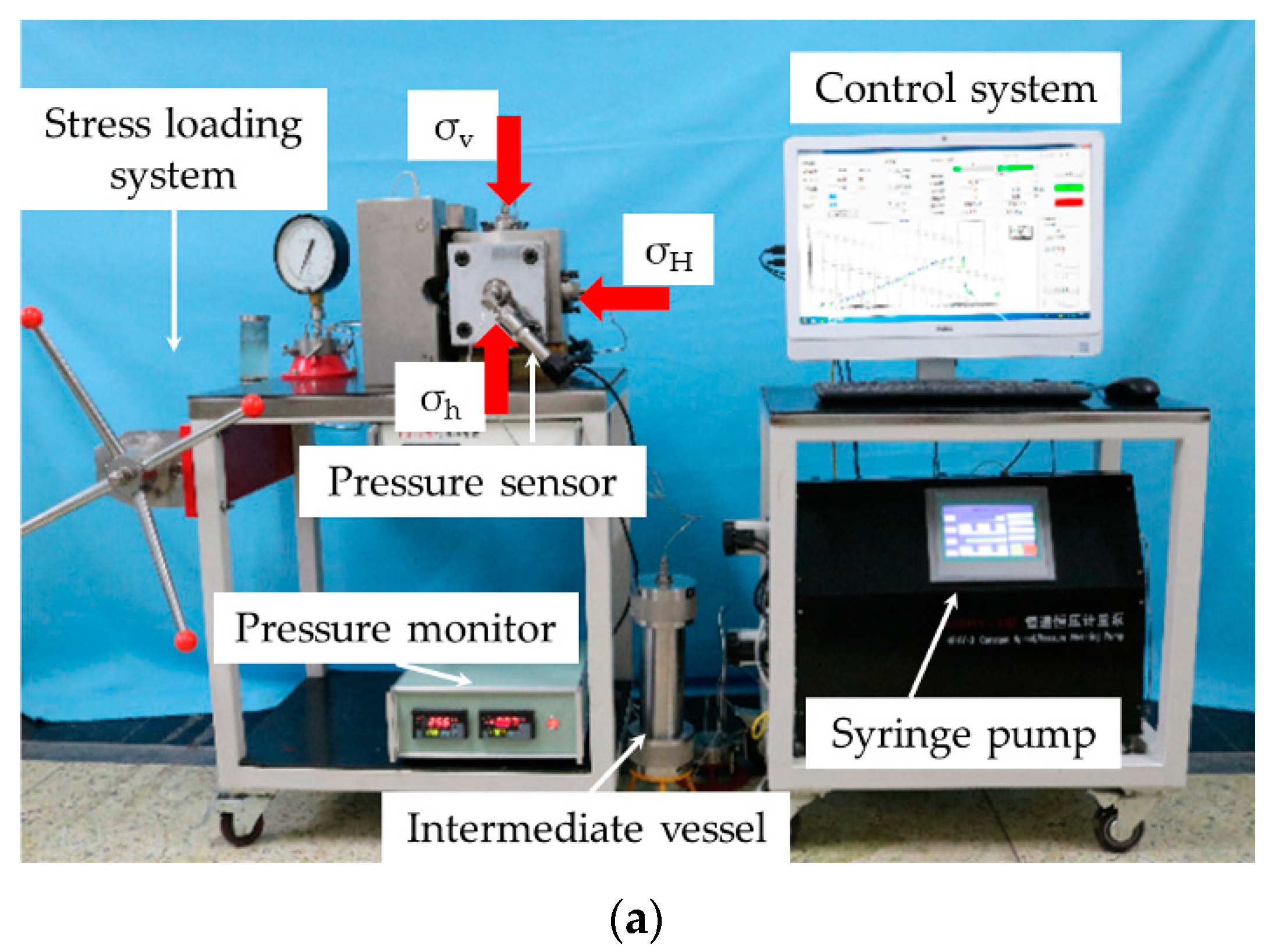
The hydraulic fracturing experiments of volcanic rocks were performed using a true triaxial fracturing system, as shown in
Figure 2. The experimental device was mainly composed of a specimen chamber, triaxial stress loading system, syringe pump, pressure sensor, data acquisition, and control device, and other auxiliary devices. The triaxial stress loading system was controlled by a set of manual pressure pumps, which provided the specimen with a maximum triaxial stress of up to 20 MPa. We applied 3D pressures to 3 separate metal sheets inside the specimen bin through the pipelines. The metal sheets were in direct contact with the surface of the specimen, and the triaxial confining pressure was applied to the specimen. Since the confining pressure device and the injection pressure device were 2 completely independent systems, the confining pressure was assumed not to be affected by the injection pressure during the injection process. The maximum injection pressure of the syringe pump was 60 MPa and the maximum injection rate was 20 mL/min. A pressure sensor was set up at the wellbore to monitor the pressure, with a measurement range of 0 to 40 MPa and an accuracy of 0.01 MPa. The control system recorded the value of the pressure sensor once per second and controlled the opening and closing of the valve.
Volcanic rock specimens for the fracturing experiment were collected from the outcrop of the Chepaizi formation in the northwest of Junggar Basin, China. The porosity and permeability of the volcanic specimens were 6.74% and 0.37 mD, respectively. The triaxial compression test result showed that the Young’s modulus and Poisson’s ratio of the Carboniferous volcanic rocks in the Junggar Basin were 40.7 GPa and 0.22, respectively. The Brazilian splitting test result demonstrated that the tensile strength of the substrate was 10.96 MPa. The deformation and failure characteristics of the Carboniferous volcanic rocks in the Junggar Basin were compared with those of shale in the Longmaxi formation of Sichuan Basin and sandstone in Shanxi formation of Ordos Basin in the triaxial compression test (
Figure 3). Rickman et al. [
24] reported that a large elastic modulus of rock resulted in high brittleness. Rock with high brittleness breaks down at low strain [
46,
47,
48,
49,
50,
51]. The stress–strain curve in
Figure 3 indicated that the elastic modulus of the volcanic rocks was slightly lower than that of shale (around 50.0 GPa) and remarkably higher than that of sandstone (around 10.0 GPa). The peak strain of the volcanic rock specimen was smaller than those of the shale and sandstone specimens, which was accompanied by a rapid stress drop in the curve. These abovementioned failure characteristics indicated the relatively high overall brittleness of the Carboniferous volcanic rocks.
In addition to brittleness, the existence of the original NFs in the rock specimens had a crucial impact on fracture morphology. In this study, rock specimens were first classified on the basis of surface observation results of the NFs during specimen preparation. As shown in
Figure 4, the specimen was cut into an 80 × 80 × 100 mm cuboid using a cutter. Then, a 15 mm diameter drilling bit was used to drill a 53 mm deep hole in the X-axis direction to simulate a horizontal wellbore. Afterward, a self-designed 12 mm diameter steel pipe column was used to simulate the formation casing. The steel pipe column was approximately 58 mm long. Finally, the wellbore was bonded with the specimen using epoxy resin to obtain an open-hole section (OHS) with a bottom length of approximately 10 mm. Fracturing fluid was injected into the specimen through the wellbore assembly equipped with the steel pipe column to simulate the fracture-making process of hydraulic fracturing.
2.2. Experimental Scheme
We mainly aimed to determine the influence of different horizontal stress differences and injection rates on the fracture propagation of volcanic reservoirs. The horizontal stress difference of the Carboniferous volcanic reservoir in Xinjiang was approximately 7 MPa. Therefore, the two-directional stress differences were determined as 5 and 10 MPa in this experiment. By respectively applying the minimum and maximum horizontal principal stress along with the X-axis and Y-axis directions and the vertical stress along the Z-axis direction, the stress state was simulated following the horizontal well completion method.
In the field test of the volcanic rock reservoir in Xinjiang Oilfield, large displacement and low viscosity slickwater fracturing were widely used, thus slickwater was used as the fracturing fluid in the experiment. The fracturing simulation experiment was first conducted by injection at a constant rate of 0.2, 2, or 5 mL/min to analyze the influence of horizontal stress difference on the fracture morphology of igneous rocks. The feasibility of improving fracture complexity in a high-level stress difference (10 MPa) reservoir using pulse injection was explored on the basis of obtained knowledge. That is, the process of fracturing was considered to achieve a certain number of alternating changes in high and low injection rates by adjusting the injection rate. At the beginning of the experiment, we did not know the internal fracture condition of the rock outcrop sample. Therefore, to avoid short fracturing time and pressure sensor sampling error caused by a high injection rate, we used a very low injection rate (0.2 mL/min) to test the length of the fracturing time (about 2700 s). From this result, we concluded that the fracturing time of 2 mL/min was about 270 s and the fracturing time for 5 mL/min was about 100 s. When exceeding 5 mL/min, the error caused by the pressure sensor acquisition frequency was too large. If less than 2 mL/min, the fracturing time was too long.
2.3. Experimental Procedure
The specimen was placed in a specimen chamber, and the wellbore assembly and fracturing pipeline were connected. The connection condition of the pipeline was checked. A hand pump was used to load triaxial stress to the minimum horizontal principal stress (5 MPa) simultaneously, and the control valve along the X-axis was closed. Maximum horizontal principal stress (10 or 15 MPa) was loaded again, and then the control valve along the Y-axis was closed. Finally, the specimen was loaded to the vertical stress (15 MPa), and the control valve along the Z-axis was closed. After the confinement stress was loaded, the pipeline was closed. The value and fluctuation range of the confinement stress was monitored by a pressure gauge.
Dye was added to slickwater for the fracturing simulation. Changes in the injection pressure data were collected and recorded in real-time using the pressure sensor on the wellbore. After determining fracture initiation and full expansion in the rock according to the response characteristics of the pressure curve, the pump injection was stopped. The rock specimen was removed after unloading the confining pressure.
As shown in
Figure 5, the fracture morphology and width characteristics on the surface of the rock specimen were observed first. The accuracy of the fracture width measuring instrument was 1 μm. Then, the rock specimen was cut into several thin slices (approximately 20 mm thick) based on the fracture distribution. Because in the NFN, the small NF itself was sufficient to produce leak-off, but these fractures may not be fully opened during hydraulic fracturing or closed up after opening. Therefore, in this paper, the difference between the HFN and the NFN was judged by adding a dye or a fluorescent. Unlike artificial fractures, the formation of NFNs was not controlled by experimental factors. Therefore, in the measurement of the fracture width, the widest fracture among the observed fractures was selected as the width of the main fracture of the specimen.
Finally, a 3D fracture model was constructed by further determining the fracture track and width in the rock.
3. Results
Table 1 lists the characteristic parameters, including breakdown pressure and breakdown time, of the pressure curve under different experimental conditions, the overall distribution pattern of the rock specimen, and the average value of the fracture width. Breakdown time was defined as the period in which pressure rises from 0.3 MPa to the fracturing pressure.
In the process of specimen preparation, a total of 16 specimens were selected for processing. However, due to the fractures caused by mechanical vibration and cutting tools, 4 samples incurred blocks drop or breaks directly along the NF during the processing. A total of 12 specimens met the experimental requirements.
During the experiment, we encountered more NFs of the rock specimens. Three specimens ended in failure in the experiment. Take the injection rate of 5 mL/min and the 3 flow pauses as an example in the first half of the experiment, the pressure curve behaved normally. However, in the continuous injection phase, we found that the breakdown pressure of the specimens was significantly lower (7 MPa) than that of the other specimens. After the specimen was sliced into 4 pieces, we found a large hole in the fracture. We think this hole caused the failure. The other specimen ruptured when the confining stress was applied because an NF was obviously weathered, the cementation strength of the fracture was greatly reduced, and the failure occurred under the effect of the horizontal stress difference. The breakdown pressure of the third failure specimen was significantly lower than the others (5 MPa), thus we repeated the experiment with another specimen.
After excluding failed experiments and similar conclusions, we finally included nine specimens for discussion.
3.1. Influence of Horizontal Stress Difference
Several laboratory experiments and numerical simulation results showed that the horizontal stress difference had a crucial influence on fracture morphology [
17,
18,
22,
30,
46,
50,
51,
52,
53,
54]. A theoretical model of the interaction between HF and NF was proposed in most studies [
25,
53,
55,
56,
57], including HF being arrested by the NF, propagating along NF, and penetrating NF. Under high-level stress differences, HF was dominant, and opening NFs with simple fracture morphology was difficult. Under a low-level stress difference, HFs easily activated NFs, forming a complex fracture network [
30,
54]. However, the critical horizontal stress difference conditions conducive to the activation of NFs in different reservoirs were inconsistent due to differences in lithology and NF properties (cementation and mechanical properties). Taking shale as an example, most literature reviews indicated the formation of a complex fracture when the horizontal stress difference was lower than 4 MPa. However, the formation of a plane fracture was observed when the horizontal stress difference was higher than 8 MPa. The range of 5 to 7 MPa pertained to the transition stress difference from the complex to the plane fracture [
17,
18,
20,
52,
53]. However, Zou et al. [
30] reported that shale specimens in the Xujiahe formation can still form a fracture network when the horizontal stress difference was higher than 9 MPa.
An NF, which was significantly different from shale in terms of lithology and mechanical properties, developed in a naturally fractured volcanic reservoir in Xinjiang Oilfield. Two groups of horizontal stress difference conditions, 10 MPa (Nos. 1, 2, and 3) and 5 MPa (Nos. 4, 5, and 6), were established to investigate the influence of horizontal stress difference on the fracture morphology of volcanic rocks. Taking Nos. 3 and 6 rock specimens, the injection rate used in the experiment was 5 mL/min.
Figure 6 shows the fracture pressure curves. This figure indicates that the pressure curves of the two groups of rock specimens showed significant linear supercharging characteristics. The supercharging speeds were 325.61 and 322.51 kPa. This finding indicated that the influence of fracturing fluid filtration was insignificant under a 5 mL/min injection rate. The breakdown pressures of rock specimens Nos. 3 and 6 were 14.4 and 12.6 MPa, respectively. Then, the pressure rapidly dropped to nearly 0 MPa.
Figure 7 and
Figure 8 show the fracture morphology of the two groups of rock specimens, including surface fracture trace and the 3D reconstruction of the fracture and fracture width characteristics.
Figure 7 shows that a strip of HF displayed crack initiation at an OHS and propagated outward under a 10 MPa horizontal stress difference. In the presence of NF, the HF deflected along the NF, then fracture initiation occurred on the other side (S4 in
Figure 7a). The overall fracture pattern was a transverse HF along the direction of the maximum horizontal principal stress. Under the 5 MPa low horizontal stress difference, a HF demonstrated fracture initiation at an open-hole section in the No. 6 rock specimen, and a NF can be activated in the propagation process, as shown in
Figure 8. The overall fracture morphology of No. 6 was more complex than that of the No. 3 rock specimen. Although the high injection rate used in the fractured volcanic reservoirs is generally beneficial for the initiation and propagation of HFs, a considerably fast pressurization rate was not conducive to the activation of the NF systems induced by HFs; especially with high-level stress differences, the fracturing effect will worsen.
3.2. Influence of Injection Rate
The injection rate is one of the important engineering factors that affect fracture morphology. At a high injection rate, HFs easily penetrate NFs directly because the pressure increases rapidly. Activating NFs and creating complex fracture networks is difficult. A low flow rate is an effective method for activating and opening NFs [
18,
30,
54]. At a low injection rate, the fracturing fluid has sufficient time to enter the NF because the pressure increases slowly. Increasing the fluid pressure in the fracture is beneficial for opening NFs to improve the complexity of the fracture significantly.
A low injection rate (0.2 and 2 mL/min) was adopted to conduct the fracturing experiment for rock specimens Nos. 1 and 2.
Figure 9 depicts the pressure curves, and
Figure 10 and
Figure 11 depict fractures morphology. At a 0.2 mL/min injection rate, the injection pressure of the No. 1 rock specimen gradually increased. When the pressure reached approximately 4 MPa, the pressure curve started to demonstrate a non-linear pressure-rising stage. Subsequently, a small pressure drop was monitored, indicating the gradual opening of the NF connecting with the wellbore (
Figure 9a) and percolating into the fracturing fluid. When the NF was filled with fracturing fluid, the rising rate of injection pressure increased again and finally reached a maximum of 9.0 MPa at 2600 s. In approximately 2700 s, a slow pressure drop appeared on the pressure curve, gradually stabilizing at approximately 8.5 MPa. This finding shows the dominance of fluid filtration in the NF network. In the process of injection, many NFs gradually opened, and the pressure was insufficient for HF initiation. The pressure was changeless when the injection rate and filtration of the NF were stable. From the surface morphology and internal reconstruction of fractures shown in
Figure 10, the NFs in the No. 1 specimen were found to be nearly fully open, forming a complex NF network. However, the opening of the fracture was small at only 95 μm (
Figure 10c), thus complicating the transport of sand by fracturing fluid.
The injection rate of rock specimen No. 2 was 2 mL/min. The injection pressure of the two specimens linearly increased in the early stage of injection. However, when the injection pressure of specimen No. 2 reached approximately 15 MPa, the slope of the pressure curve gradually decreased, indicating the slight increase in opening of the NFs connecting with the wellbore and the increase in the leak-off rate of the fracturing fluid. When the injection time of specimen No. 2 reached 142 s, the rock specimen broke down with a fracture pressure of 18.1 MPa. The injection pressure of No. 2 later linearly dropped to approximately 2 MPa. The reconstruction of the surface and 3D fractures of the rock specimen (
Figure 11) showed that at a 10 MPa high horizontal stress difference, only one evident HF appeared in the No 2. specimen, whereas the number of NFs was limited. The fracture width test result showed that compared with specimen No. 1, the fracture width of No. 2 rock specimen significantly increased by approximately 222 ± 1 μm but was less than that of No. 3. This result indicates that a high injection rate is beneficial for improving fracture width.
The comparison of the above experiments indicated that at a 5 MPa horizontal stress difference, the key to the generation of a complex fracture network was enabling the connection of opened HFs with additional NFs because they were easy to open. If the NF opening was large, then the fracture network becomes complex. At a 10 MPa horizontal stress difference, the NF can only be opened at a low injection rate. However, the leak-off of fracturing fluid was high at low injection rates, thus easily resulting in sand plugging in practice. Opening NFs at low injection rate sand forming HFs at high injection rates was easy. Combined with such characteristics, the feasibility of improving the fracturing effect using pulse pump injection was explored at high horizontal stress differences.
3.3. Influence of Pulse Pump Injection
Volcanic reservoirs, wherein fractures generally develop, have considerable heterogeneity [
8,
9]. Large-scale NFs improved the complexity of fracture networks but negatively affected the propagation of HF. NFs generally have much lower strength than the rock matrix, thus that HF requires less energy to propagate along NFs. The pulse pump injection with high and low injection rate alternations was used to reduce the filtration influence of the fracturing fluid and avoid the rapid growth of HFs, and cannot effectively activate NFs. This approach was also adopted to ensure that the fracturing fluid was allowed sufficient time to enter the NF to improve the pore fluid pressure. At a later stage of pump injection, the high injection rate was adopted again until the rock specimen broke.
We designed experiments Nos. 7–9. The pressure pulse was formed by alternating injection rate between high (2 and 5 mL/min) and low (0.2 mL/min) injection rates. Based on the experimental results of specimens Nos. 1–6, the breakdown time was approximately 150 and 40 s at injection rates of 2 and 5 mL/min, respectively. Therefore, at injection rates of 2 and 5 mL/min, the duration of the low-flow section were 20 and 10 s, respectively. The 3-section pulse and 2 mL/min injection rate were first used for specimen No. 7 (
Figure 12). Then, a 5-section pulse was used for specimen No. 8 (
Figure 13). Finally, the injection rate was increased to 5 mL/min for specimen No. 9 (
Figure 14).
As shown in
Figure 12, an injection rate of 2 mL/min was used for specimen No. 7. When the injection pressure reached 0.3 MPa, the time was set to 20 s, and the injection rate was lowered to 0.2 mL/min for a 20 s injection. Afterward, the injection rate was increased to 2 mL/min. The pressure curve demonstrated instability before 70 s. The pressure rapidly dropped with a low injection rate. This result indicated that the fluid in the wellbore filled during the sampling of this section, and no filtration of NF formed. At the second and third low injection rate stages, the drop rate of the injection pressure was relatively small, at approximately 1.87 kPa/s. This indicated that the leak-off effect of the fracturing fluid was insignificant. After three pulses, the injection was continuously conducted at an injection rate of 2 mL/min for specimen No. 7. Finally, a fracture appeared after 185 s of injection with a fracture pressure of 15.7 MPa. Subsequently, the pressure directly dropped to approximately 0.3 MPa. The fracture morphology showed that HFs were dominant in specimen No. 7 without evident NF openings on the rock specimen surface. The fracture morphology dominated by HF was similar to that of specimen No. 2, mainly due to the relatively low injection pressure in the pulse stage (less than 5 MPa); the influence on NFs openness was unremarkable. At the low injection rate stage, the filtration of fracturing fluid to the NF was limited, and the fluid pressure in the NF was low. At the later stage, the continuous injection of 2 mL/min played a critical role in the formation and propagation of the entire fracture.
The injection rate at 2 mL/min was maintained for specimen No. 8. The number of pulse sections increased to 5, and other conditions remained unchanged. The pressure curve showed that the slope of the pressure drop at a low injection rate changed with the increasing pulse cycles. The pressure continued to fluctuate in the first low injection rate section. The drop slopes of the second and third pressure curves were 1.80 kPa/s, which was similar to the pressure response of rock specimen No. 7. In the fourth and fifth low injection rate sections, the dropping rate of the pressure curve apparently increased to 5.57 and 9.45 kPa/s, respectively. This result was due to the increased opening of several NFs caused by the injection pressure (approximately 6 and 8 MPa) during the injection rate switching between the fourth and fifth sections, thus increasing the filtration rate of the fracturing fluid. The final fracture pressure of the specimen was 16.4 MPa. The pressure directly dropped to below 0.3 MPa with a breakdown time of 238 s. The fracture width was 282 ± 2 μm. Before the final fracture pressure, the pressure curve differed from those of specimens Nos. 2 and 7, and the pressure increasing rate remained the same. The pressure curve linearly decreased when the fracture pressure was reached. This observation indicated that the NF was fully opened in specimen No. 8. From the fracture morphology, HF and many opened NFs were found on the surface of No. 8. This result showed an overall fracture morphology that was more complex than that of specimen No. 7. As shown in
Figure 13, a HF was arrested when it contacted a NF, and the NF opened. A comparison between specimens Nos. 7 and 8 showed that increasing the number of pulses can promote the creation of a complex fracture network, mainly because the injection pressure in the fourth and fifth pulse stages was sufficient to open the NF, which was conducive to fracturing fluid filtration to improve the fluid pressure in the fracture.
The injection rate for specimen No. 9 was set to 5 mL/min and the number of pulses was 5. The pressure curve showed that at the first change to a low injection rate, the injection pressure was low: 4 MPa. At this moment, the opening of the NF connecting with the OHS did not change significantly and the leak-off was not evident. In the second and third pulse cycles, the drop rate of the injection pressure in the low injection rate injection stage gradually increased to 5.97 and 8.32 kPa/s in the second and third cycles, respectively. This increase was due to the high injection pressure (i.e., 8 and 12.5 MPa) during injection rate switching, the slightly increased NFs opening, and the accelerated leak-off rate of the fracturing fluid. In the later stage of the fourth high injection rate stage, nonlinear characteristics were observed from the pressure curve. This observation indicates that the NF opening further increased. When the injection rate was changed to 0.2 mL/min again, the injection pressure reached 15.5 MPa. Afterward, the injection pressure rapidly dropped at a rate of approximately 44.95 kPa/s. In the fifth high injection rate stage, when the injection pressure rose to 16.6 MPa (
Figure 14a, 102 s), an evident pressure drop appeared with a declining range of 2.7 MPa. Then, the injection pressure rose again. This trend indicated the occurrence of local fracture or the activation of NFs in the rock specimen at this moment. After changing to low injection rate in the fifth section, the pressure drop rate was the same as in the fourth section. This result showed that the NFs were fully opened in the fourth and fifth sections; simultaneously, a pump injection–filtration balance formed and stabilized. The final fracture pressure for specimen No. 9 was 20.6 MPa, which was the highest pressure among all specimens. The pressure dropped to 0.3 MPa after the specimen fractured in a straight line, with a breakdown time of 122 s and a fracture width of 365 ± 2 μm. The nonlinear characteristics of the pressure curve were significant before the fracture pressure was reached for specimen No. 9. This finding indicated that the HF fracture initiation mode of specimen No. 9 differed from those of Nos. 3 and 8 (with the same horizontal stress difference and injection rate). Specimen No. 9 achieved HF fracture initiation twice. Based on the fracture distribution and internal reconstruction, we found two cross-fractures in an OHS, which combined in the expansion process. The opening of the principle HF, with a fracture width of 365 ± 2 μm, was evident. The HF deflected along the NF in the propagation process, and the number of NFs was high, with many branch cracks observed on the surface of the rock specimen.
4. Discussion
The creation of a complex fracture network plays an important role in the development of unconventional oil and gas reservoirs. Determining how to activate the natural fracture system is a critical problem to be solved by petroleum engineers. In this study, a series of laboratory fracturing experiments were performed to investigate the propagation mechanism of HF in naturally fractured volcanic formations. The experimental results showed that the horizontal stress difference and injection rate considerably influenced the ultimate fracture geometries. When the injection rate was low (0.2 mL/min), fluid leak-off was dominant due to the existence of a highly permeable NFN. In this case, HF initiation was difficult, and the aperture of the fracture was limited. As a consequence, the risk of sand plug occurrence increased. The conductivity of the fractures was generally insufficient for the long-term development of oil and gas. Increasing the injection rate was demonstrated to be beneficial for the initiation and propagation of HF. Under high injection rates of 2 and 5 mL/min, we observed that HFs were created. However, the activation of the NFN was restricted, especially under the confinement effect of the high horizontal stress difference of 10 MPa. This occurred because the high injection rate caused quick pressurization and decreased the time of fluid leak-off into the NFs. This mechanism has also been discussed by Li et al. [
58,
59]. Based on the abovementioned results, the injection scheme for naturally fractured volcanic formations should be optimized. In previous studies, cyclic injection [
60,
61] was developed and laboratory tested. However, this injection scheme was designed to reduce the breakdown pressure of intact granite.
Herein, multiple flow pulses were used to improve the fracture network complexity during stimulation treatment in naturally fractured volcanic formations. The experimental results show that multiple flow pulses are helpful for generating a complex fracture network and increasing the fracture aperture. Under the 2 mL/min injection scheme with 3 pulses (
Figure 12), the increase in fracture complexity was limited because the injection pressure during the pulse stage was low (<5 MPa). When the number of the flow pulses was increased to 5 (
Figure 13), the injection pressures during the fourth and fifth intermittent low-rate pulse stages were higher than 5 MPa. The pressure drop rate significantly increased, indicating an increase in the apertures of NFs and enhancement of the fluid leak-off effect. Consequently, a complex fracture network was generated by the HF activating multiple NFs. Under the 5 mL/min injection scheme with 5 pulses, besides the effect on enhancing fluid leak-off into NFs (the second and third intermittent low-rate pulse stages,
Figure 14), a sharp injection pressure drop was observed during the later flow pulse stages (the fourth and fifth intermittent low-rate pulse stages,
Figure 14), indicating the activation of NFs. In this case, the complexity and the aperture of the ultimate fracture network further increased. Although the feasibility of multiple flow pulses in a naturally fractured volcanic formation was demonstrated, the optimization of injection parameters (i.e., the interval time of flow pulse) should be further investigated.


