Article

Multiobjective Optimization for the Greener Synthesis of Chloromethyl Ethylene Carbonate by CO2 and Epichlorohydrin via Response Surface Methodology

School of Engineering, London South Bank University, 103 Borough Road, London SE1 0AA, UK
*
Author to whom correspondence should be addressed.
Energies 2020, 13(3), 741; https://doi.org/10.3390/en13030741
Submission received: 27 November 2019 / Revised: 15 January 2020 / Accepted: 18 January 2020 / Published: 8 February 2020
(This article belongs to the Special Issue Carbon Dioxide (CO2) Utilization)

Abstract

:
In this paper, a statistical analysis with response surface methodology (RSM) has been used to investigate and optimize process variables for the greener synthesis of chloromethyl ethylene carbonate (CMEC) by carbon dioxide (CO2) and epichlorohydrin (ECH). Using the design expert software, a quadratic model was developed to study the interactions effect between four independent variables and the reaction responses. The adequacy of the model was validated by correlation between the experimental and predicted values of the responses using an analysis of variance (ANOVA) method. The proposed Box-Behnken design (BBD) method suggested 29 runs for data acquisition and modelling the response surface. The optimum reaction conditions of 353 K, 11 bar CO2 pressure, and 12 h using fresh 12% (w/w) Zr/ZIF-8 catalyst loading produced 93% conversion of ECH and 68% yield of CMEC. It was concluded that the predicted and experimental values are in excellent agreement with ±1.55% and ±1.54% relative errors from experimental results for both the conversion of ECH and CMEC yield, respectively. Therefore, statistical modelling using RSM can be used as a reliable prediction technique for system optimization for greener synthesis of chloromethyl ethylene carbonate via CO2 utilization.

Graphical Abstract

1. Introduction

Carbon dioxide (CO2) chemistry has earned enormous interest in recent years due to its abundance and inexpensive nature. It is a nontoxic, non-flammable, easily available, and typical renewable C1 source of organic synthesis [1]. CO2 is an important “greenhouse” gas that has drawn greater attention in line with the need for the development of green engineering and sustainable society. In this regard, the development of environmentally benign and efficient synthetic of chemical utilization of CO2 has been a subject of immense research in academia as evidenced by the rising number of publications in all areas of CO2 management [2]. Although CO2 fixation is unlikely to consume large quantities of CO2 in the atmosphere, this measure can be regarded as a significant strategy for the development of sustainable and safe processes [3]. With the intriguing applications of organic carbonates, the use of CO2 as a raw material to synthesize cyclic organic carbonates has gained extensive attention in chemical industries [4].
Organic carbonates are versatile compounds used as raw materials for many industrial applications including raw materials for polycarbonates and polyurethane synthesis [5], green solvents [6], gasoline [7], fuel additives [8], electrolytes in energy storage devices [9], and fine chemical intermediates for pharmaceuticals [10], automobiles [11], electronics [12], and alternative for fuels [12]. Five most important organic carbonates which have attracted significant research interest in recent years include dimethyl carbonate (DMC), diethyl carbonate (DEC), glycerol carbonate (GC), propylene carbonate (PC), and ethylene carbonate (EC) [13].
Organic carbonates have unquestionably gained popularity within the context of CO2 utilization campaign. However, one of the major challenges faced by chemical industries today is developing the right catalyst with the viewpoint of greener and sustainable environment. In the last decades, the use of homogeneous catalysts for the production of organic carbonates was prevalent [14]. This includes quaternary ammonium salts [15], ionic liquids [16], alkali metal salts [17,18], salen Cr(III) complexes [19], salen Co (III) complexes [20], and salen Mn (III) complexes [21,22]. Some of the reasons for preference of homogeneous catalyst over solid heterogeneous catalyst include a high turnover number (TON) [22,23], higher catalytic activity and selectivity. However, homogenous catalysts have been identified with a number of environmental and economic drawbacks including high cost of catalyst production [24], rigorous separation and purification of products [24,25], production of toxic species [26], use of co-solvent [27], problem of catalyst reusability [27], and catalyst instability at room conditions [28]. As a result of these drawbacks, extensive research efforts in catalysis have brought to spotlight the incredible advantages of heterogeneous catalyst for the synthesis of organic carbonates [29]. Heterogeneous catalysts such as metal organic framework (MOFs) catalysts offers several technical advantages such as stability, separation, handling, and reuse of the catalyst and reactor design.
Heterogeneous catalysis offers several technical advantages such as stability, separation, handling, and reuse of the catalyst and reactor design [30]. Metal organic framework catalyst (MOF), is a new line of heterogeneous catalyst with tremendous results for synthesis of organic carbonates. MOF catalysts, also known as multidimensional porous coordination polymers, are microporous crystalline materials with exceptional properties such as ultrahigh specific surface area, enormous pore spaces, and ordered crystalline structure [30,31]. MOFs have emerged as a suitable candidate for the cycloaddition of CO2 and epoxide in the synthesis of organic carbonate due to their heterogeneity and reusability requirements [32]. The development of an efficient and stable Zr/ZIF-8 catalyst for the synthesis of chloromethyl ethylene carbonate (CMEC) from epichlorohydrin (ECH) and CO2 is a promising greener technology for CO2 utilization. Incorporating zirconium into ZIF-8 has undoubtedly increased ZIF-8 stability as well as the catalytic performance of Zr/ZIF-8 during the series of experiments.
Within the context of chemical engineering, low product yields have been attributed to a number of factors including the use of unsuitable choice of catalyst [33], problems achieving the right optimum reaction conditions [33], and inappropriate application of other input parameters [34]. In recent years, optimizing system variables to improve product yields has been the focus of many different fields of research. Response surface methodology (RSM) is a collection of statistical and mathematical techniques based on the multivariate non-linear model for optimizing processes [35]. RSM has received considerable interest in many industrial processes in an attempt to construct empirical models able to correlate the statistical relationships (if any) between a set of variables making up an industrial system [36]. Saada et al. [37] have successfully modelled and optimized the synthesis of organic carbonates with five independent variables at three-level (35) factorial design. Their results have been validated using regression analysis.
Several authors including AboElazayem et al. [38] and Onyenkeadi et al. [39], have criticized the traditional “trial-and-error” optimization methods and “one-factor-at-a-time” (OFAT) as time-consuming and considered quite expensive due to a large number of samples and experimental trials involved. Another drawback identified with traditional optimization methods is low overall efficiency [40]. Sadeghi and Sharifnia [41], describe OFAT as a method that excludes the interactive effects among the variables and does not express the complete effects of the parameters on the process. In order to overcome these drawbacks, Yu and He [42] suggested multivariate statistical techniques, which are full three-level factorial designs: Box-Behnken designs, central composite designs, and Doehlert designs.
A multivariate optimization technique is a statistical tool for analyzing complex non-linear processes. This is especially useful when interactions are not known or optimal process parameters are to be determined in order to make a process more robust [43]. It is cost-effective as fewer experimental trials are required, high computational efficiency [44], and it requires very little or no human experience to obtain an accurate and satisfactory results [45]. Therefore, the systematic application of RSM optimization for the catalytic conversion of epichlorohydrin (ECH) and carbon dioxide (CO2) to chloromethyl ethylene carbonate (CMEC) can be regarded as an innovative way of CO2 utilization.

2. Experimental Methods

2.1. Chemicals and Materials

Acetone (99%), chloromethyl ethylene carbonate (99%), epichlorohydrin (purity; 99%), zinc nitrate hexahydrate (Zn(NO3)2⋅6H2O (purity; 99%), dimethylformamide (purity; 99%), and zirconium (IV) oxynitrate hydrate (ZrO(NO3)2·6H2O, 99.99%) were purchased from Sigma-Aldrich Co. LLC, Dorset, UK. Methanol (99%) and n-pentane 99.8%) were both procured from Fisher Scientific UK Ltd, Loughborough, UK. ZIF-8 catalyst was purchased from Sigma-Aldrich Co. LLC under the trademark of Basolite Z1200. All chemicals and catalysts were used without further purification or pre-treatment.

2.2. Catalysts Preparation

Zirconium-doped ZIF-8 (Zr/ZIF-8) was synthesized according to a method, which was previously described elsewhere [46,47]. Briefly, 8 mmol of zinc nitrate hexahydrate (Zn(NO3)2·6H2O, purity 99.99%) and zirconium (IV) oxynitrate hydrate (ZrO(NO3)2·6H2O, purity 99.99%) solutions in a stoichiometric ratio of Zn: Zr = 9:1 were dissolved in 6.2 mmol of methanol. A separate solution of 14.2 mmol of 2-methylimidazole and 600 mml of methanol was prepared in another flask which was added by dropwise addition to the Zr-Zn based solution. The mixture, conducted in an ambient temperature under nitrogen gas flow, was vigorously stirred for 6 hrs. The crystals were collected and separated by centrifugation at 300 rpm for 30 min. The solution was washed thoroughly with methanol three times and then dried at room temperature. The crystals were left to dry overnight at 373 K. The greyish-white powders of Zr-ZIF-8 sample were further washed with DMF for 24 h in order to remove any excess of an unreacted organic linker. The solution was then heated at a temperature of 373 K in order to activate it. The sample was allowed to cool down to room temperature naturally before been capped in a vial and refrigerated, which was ready for use in catalytic reactions.

2.3. Proposed Reaction Mechanism and Reaction Pathways

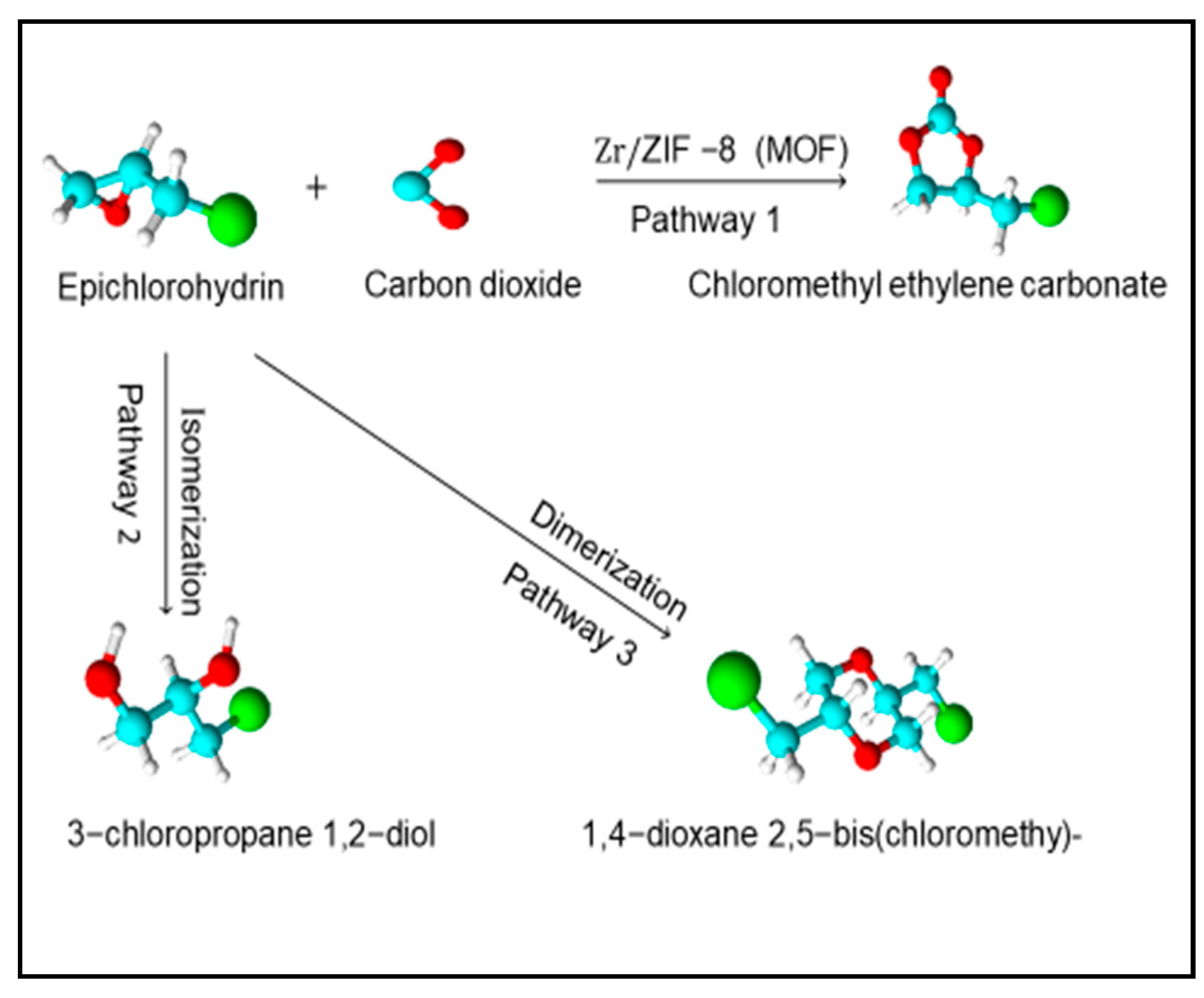
On the basis of our experimental results and theoretical understanding, we proposed a plausible reaction mechanism for the coupling reaction of ECH and CO2. Figure 1 shows the reaction mechanism was initiated by coordination of ECH with Lewis acid site Zn2+ to form the adduct of zinc-epoxide complex, then nucleophilic interaction on the electrophilic carbon of CO2 (step 1). At the same time, the acidic sites (unsaturated coordinative Zn or structural defects) of Zr/ZIF-8 interact with the oxygen atom of an epoxide (step 2). The activated CO2 attacks the less sterically hindered carbon atom of epoxide, which results in the epoxide ring-opening (step 3). Finally, the ring-closure step takes place between the O−anion and carbon atom in the intermediates to produce CMEC (step 4). Figure 2 shows the reaction pathways 1, 2, and 3 with some by-products. The decline in selectivity and CMEC yield was expected because the gas chromatography mass spectroscopy (GC-MS) analysis of the samples shows that 17.3% of 3-chloropropane 1,2-diol and 14.1% 2,5-bis (chloromethyl)-1,4-dioxane (by-products) have been formed at 353 K. Similar by-products and results have been reported by Zhou et al. [48]. This may explain in part why a drop in selectivity and yield of CMEC was recorded.

2.4. One-Factor-at-a-Time (OFAT) Analysis

OFAT analysis was developed to determine the preliminary effective range of the selected parameters for statistical analysis. The effect of four-single factors (temperature, pressure, reaction time, and catalyst loading) were evaluated for the synthesis of chloromethyl ethylene carbonate. The OFAT analysis investigated all the four parameters in the following range: Reaction temperature K (313, 323, 333, 343, 353, 363, 373); pressure (bar) (4, 6, 8, 10, 12, 14, 16); catalyst loading (%) (w/w) (5, 7.5, 10, 12.5, 15); reaction time (h) (4, 6, 8, 10, 12, 14, 16).

2.5. Experimental Design

Based on the OFAT results, a three-level, four-factor (34) factorial design with 29 runs of experiments were suggested for this study in order to determine the responses (conversion and yield). In this design, all the four factors were varied simultaneously over a set of experimental runs. To avoid bias, the suggested set of experiments were carried out randomly and the four factors, temperature, pressure, catalyst loading, and reaction time have been labelled as x1, x2, x3, and x4, respectively as shown in Table 1. The variables and their coded and uncoded values are presented with each level and range as given below in Table 1 (i.e., −1, 0, 1).
The total number of experiments (N) is given by Equation (1):
N = k2 + K + Cp
where, k is the number of independent variables, Cp is the replicate number of the center point.

2.6. Statistical Analysis

The empirical mathematical model showing the effect of the independent variables x1, x2, x3, and x4 on the predicted response Y was investigated using the second order polynomial regression equation with backward elimination.
A quadratic equation derived using RSM for the model is shown using Equation (2):
Y = b o + i = 1 n b i x i + i = 1 n b i i x i 2 + i = 1 n 1 j > 1 n b i j x i x j +   ε
where Y is the predicted response, xi and xj are the independent variables in coded levels (I ≠ j), bi, bii, and bij are the coefficients for linear, quadratic, and interaction effects, respectively, b0 is the model coefficient constant, n is the number of factors, and ε is the model random error [49].
The adequacy of the predicted models was validated by a number of statistical tools such as correlation coefficient (R2), adjusted coefficient of determination (R2adj), and the predicted coefficient of determination (R2pred). The statistical significance of the predicted model was analyzed by (ANOVA) using a regression coefficient by conducting the Fisher’s F-test at 95% confidence level [50]. Design Expert 11 software (Stat-Ease Inc., Minneapolis, MN, USA) was used for the design of experiment, regression, and graphical analysis. Statistical significance of the results have been presented by p < 0.05 and mean ± SE. The fit quality of the polynomial equation has been proved by R2.

2.7. Experimental Procedures

In a typical cycloaddition reaction, chloromethyl ethylene carbonate (CMEC) was synthesized from epichlorohydrin (ECH) and carbon dioxide (CO2) in a solvent free and co-catalyst free conditions. A 25 mL stainless steel autoclave reactor equipped with a stirrer, thermocouple, heating mantle, and controller was initially charged with the required amount of limiting reactant ECH and a known amount of Zr/ZIF catalyst. The reactor was then heated to a specific temperature and continuously stirred. When the desired reaction temperature was reached, a known amount of liquid CO2 was injected to the reactor via SCF pump at an assumed t = 0. The reaction mixture was left stirring and monitored for a set period of time.
After the reaction was completed, the reactor was cooled down to room temperature using an ice bath, depressurized, and then the reaction mixture was filtered. The catalyst was separated, washed with acetone, and dried in a vacuum oven. The product obtained from the filtered reaction mixture was then analyzed using gas chromatography (GC).

3. Results and Discussion

3.1. Analysis of Variance (ANOVA)

An analysis of variance (ANOVA) was performed using the Design Expert software in order to investigate the fitness and significance of the model for each regression coefficient. The empirical analysis of RSM model used to correlate the interactive relationship between the controlling factors (x1, x2, x3, and x4) and the predicted response Y (conversion of ECH and yield of CMEC) are shown in Table 2 above. The results of the experimental trials at various process conditions show the range of the responses from 42% to 93% of ECH conversion and 16% to 68% of CMEC yield. This trend is consistent with the results published by Onyenkeadi and colleagues. The predicted values sufficiently correlate with the observed values and fit the RSM model design for this study. The best fitting model was established by a regression analysis using Design Expert software. Fitting of the data to various models (linear, two factors interactions (2FI), quadratic, and cubic polynomials) and their following analysis of variance (ANOVA).

3.2. Development of Regression Model

In this study, the purpose of using the RSM was to generate a statistical model that demonstrated mutual interaction between the responses and the effective variables. Through the experimental matrix generated in a randomized run of experiments, the obtained responses are given using second order polynomial regression equation with backward elimination as shown below. The equations show the empirical relationship between the conversion of ECH and the yield of CMEC and the experimental factors in coded forms.
Y1= 84.15 + 8.75 x1 + 8.86 x2 + 7.22 x3 + 7.500x4 9.005 x1x2 + 7.25 x1x3 + 4.15 x1x4 2.150 x2x3 + 2.10 x2x4+ 1.10 x3x4 11.45 x12 + 0.80x22 7.10 x32 7.30 x42
Y2= 64.15 + 9.10 x1 + 6.30 x2 + 10.30 x3 + 8.70 x4 12.15 x1x2 + 7.25 x1x3 + 5.25 x1x4+ 5.40 x2x3+ 6.30 x2x4 + 5.60 x3x4 14.40 x12 7.55 x22 12.75 x32 12.15x42
Y1 and Y2 are the response variables: ECH conversion and CMEC yield. The independent variables are x1, x2, x3, and x4 which are reaction temperature, pressure, catalyst loading, and reaction time, respectively. The results of interaction effects between the independent variables were deduced as follows: Temperature-pressure; x1x2, temperature-catalyst loading; x1x3, temperature-reaction time; x1x4, pressure-catalyst loading; x2x3, pressure–time; x2x4 and catalyst loading–reaction time; x3x4. Finally, the excess of each independent variable was represented as follows: Temperature-temperature; x12, pressure-pressure; x22, catalyst loading-catalyst loading; x32 and reaction time –reaction time; x42.

3.3. Statistical Analysis of Regression Model

The response model calculated for this study has demonstrated a high degree of accuracy with an R2 of 0.9973 and an R2adj of 0.9954 at a confidence level of 95%. This agrees well with the result of [51] where the determination coefficient values, R2 and R2adj, for the reliability of the model fitting, were calculated to be 0.9932 and 0.9658, respectively. Mäkelä et al. [52], also suggested that a good model fit should yield an R2 of at least 0.8. Furthermore, the values of R2 and R2adj are close to 1.0. This demonstrates that a mutual correlation exists between the experimental and the predicted values. Therefore, the statistical significance of the second-order polynomial equation for this design shows that the regression model is statistically significant (p < 0.0001) and the lack of fit test is non-significant (p > 0.05) relative to the pure error.
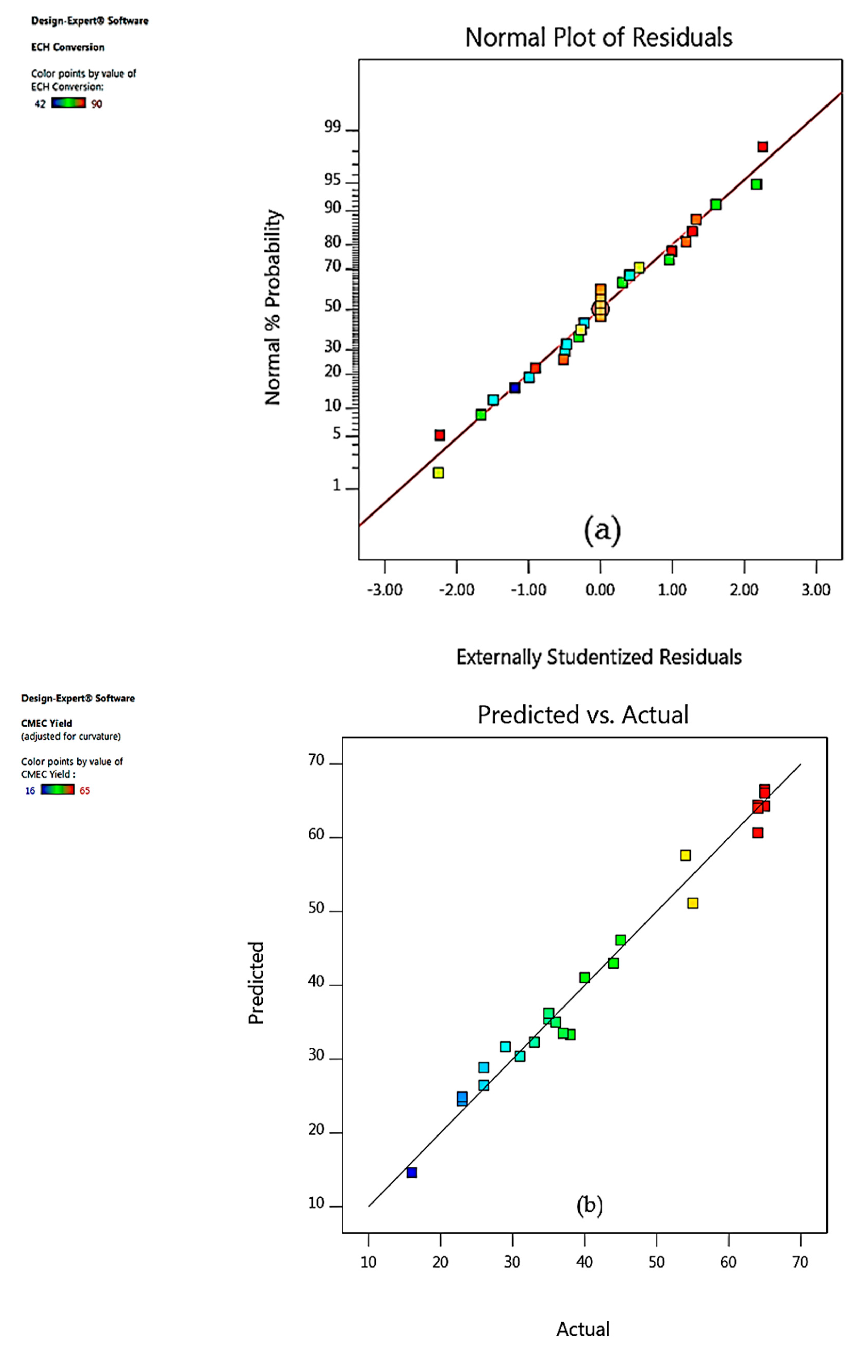
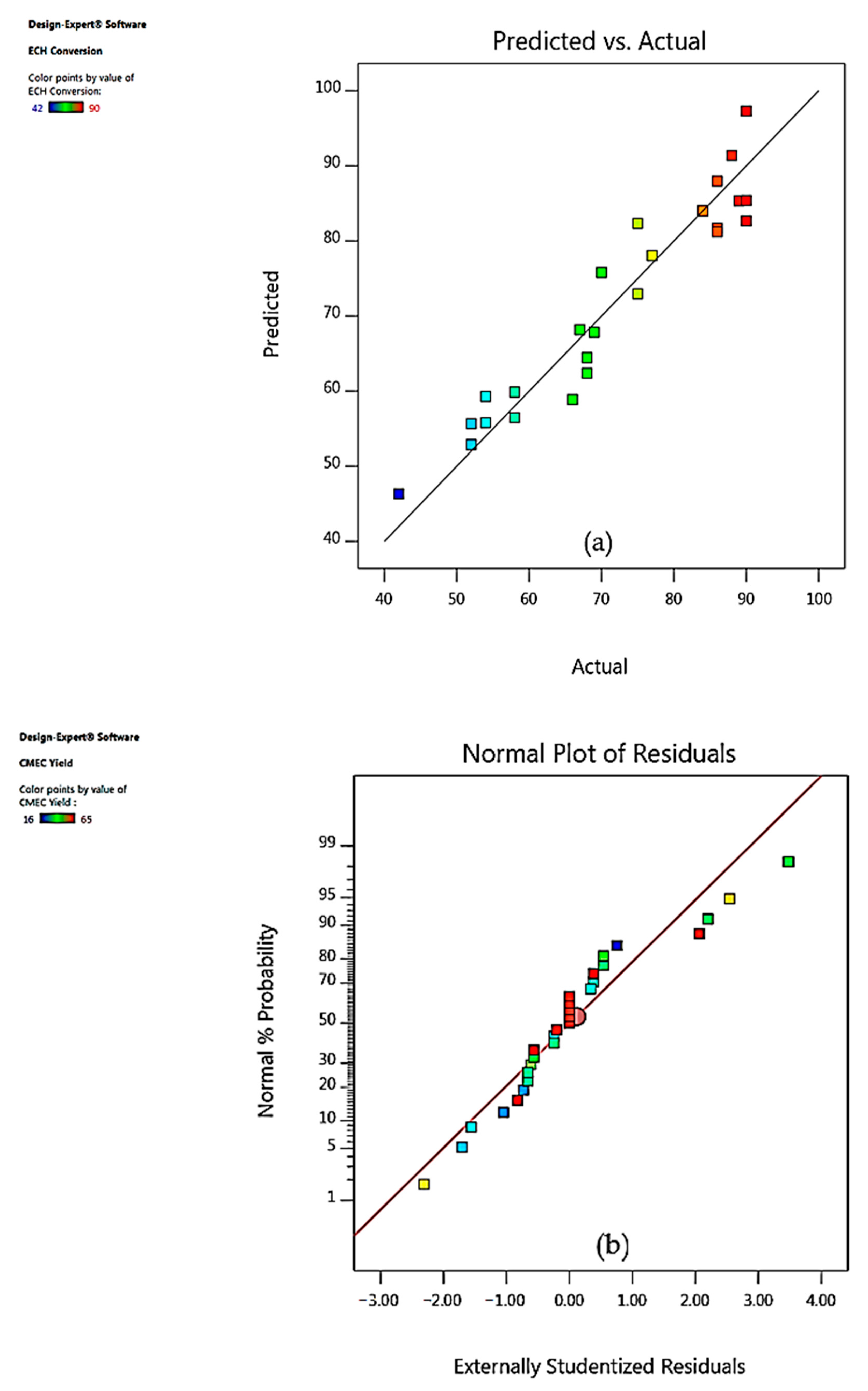
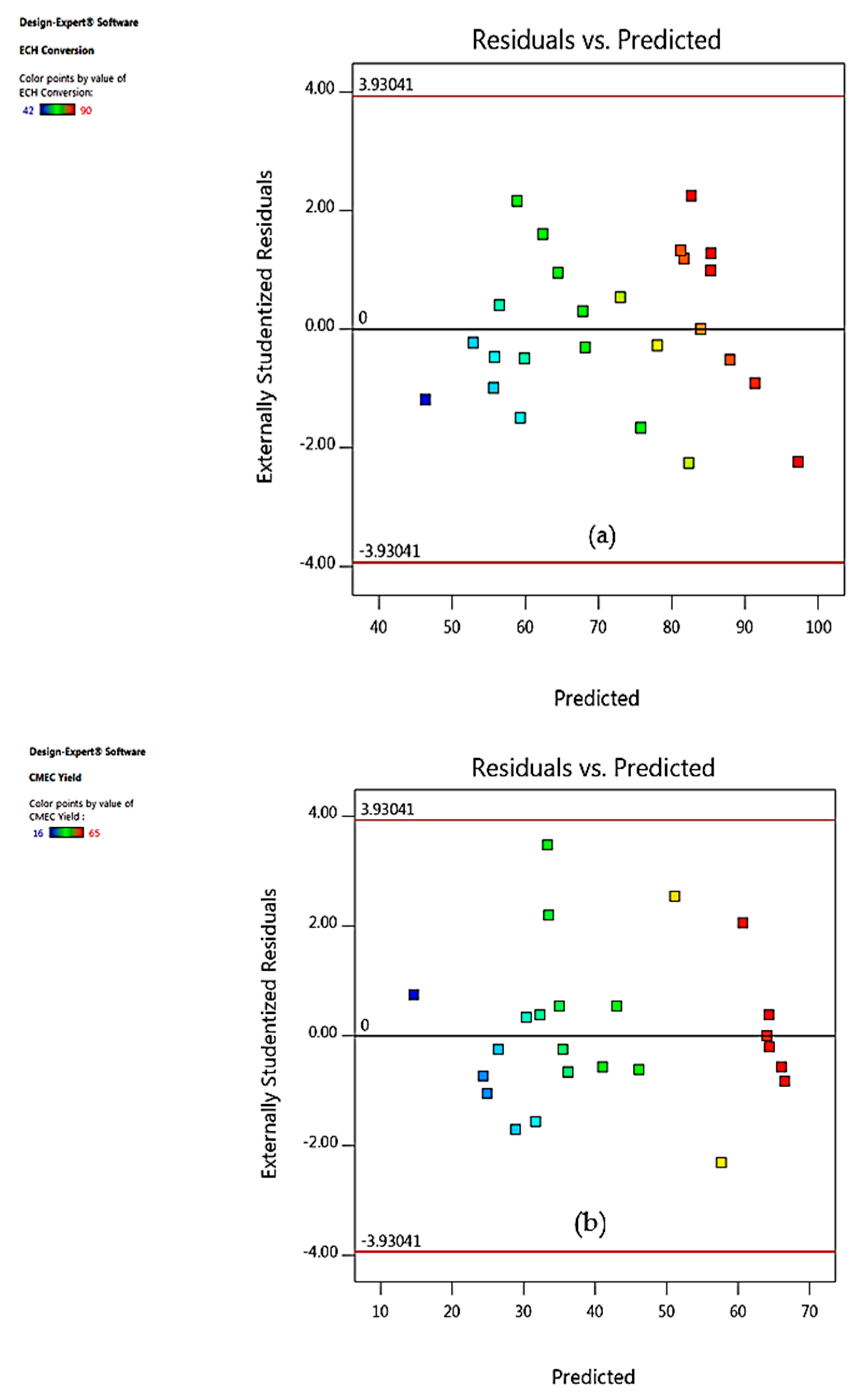
The following assumptions have been used to conclude the statistical adequacy checking of the model based on the ANOVA results. The first assumption is the similarity between the predicted and actual data of the two models as shown in Figure 3. This demonstrated that the variations between Figure 3a,b are statistically non-significant (NS) and the predicted model can be said to show a high level of accuracy and adequacy. Another assumption is the normality of the residuals. The plot of residuals has been investigated using normal plot where most of the points approximately form a straight line as shown in Figure 4a,b. This shows that residuals for both ECH conversion and CMEC yield are in normal distribution. This assumption is consistent with the report of Mäkelä et al. [52]. Thirdly, the randomization of the residuals have also been assessed using a plot between the residuals versus predicted responses. The random distribution in Figure 5 shows lack of clear structure with a normal distribution at zero mean and variance [53]. It can be observed in Figure 5a,b that points above and below the diagonal line show areas of over or under prediction with no definite structure.

3.4. Model Fitting and Adequacy Checking

In order to verify the model for fitting and adequacy test at 95% confidence level, it was necessary to apply analysis of variance (ANOVA). As shown in Table 3 and Table 4, the ANOVA results indicated a good model fit with the model. F-value is 0.44 (Table 3) and the probability > F of less than 0.0001 implied that this model was significant. The lack of fit test (non-significant: p > 0.05) was also considered a good statistical indicator for the model adequacy checking as it relates the residual error to the pure error from the replica design point [54]. As indicated in ANOVA Table 3 and Table 4, the conversion of ECH and CMEC yield was significantly (p < 0.05) influenced by the interactive and quadratic effects of all the independent variables.

3.5. Response Surface Plots Analysis

After the regression models had been built and model adequacy checking was tested, 3D response surface plots and their corresponding 2D contour plots were drawn for a model equation. Different shapes of the contour plots indicate different levels of interaction between two variables. For example, an oval plot represents significant interactions between the two selected variables while a circular plot means otherwise [54]. According to Rabiee et al. [55], 3D response surface promotes understanding of system behavior. It is also significant in recognizing the characters of response surface [56].

4. Effect of One Factor at a Time Experiments on Responses (OFAT)

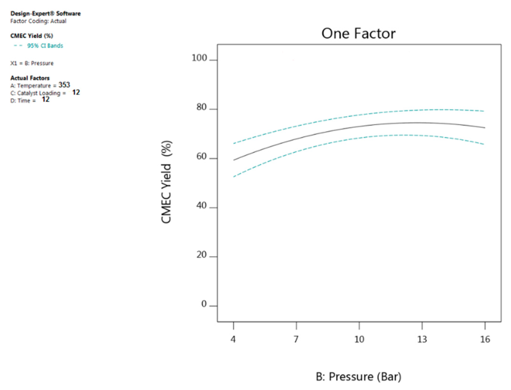
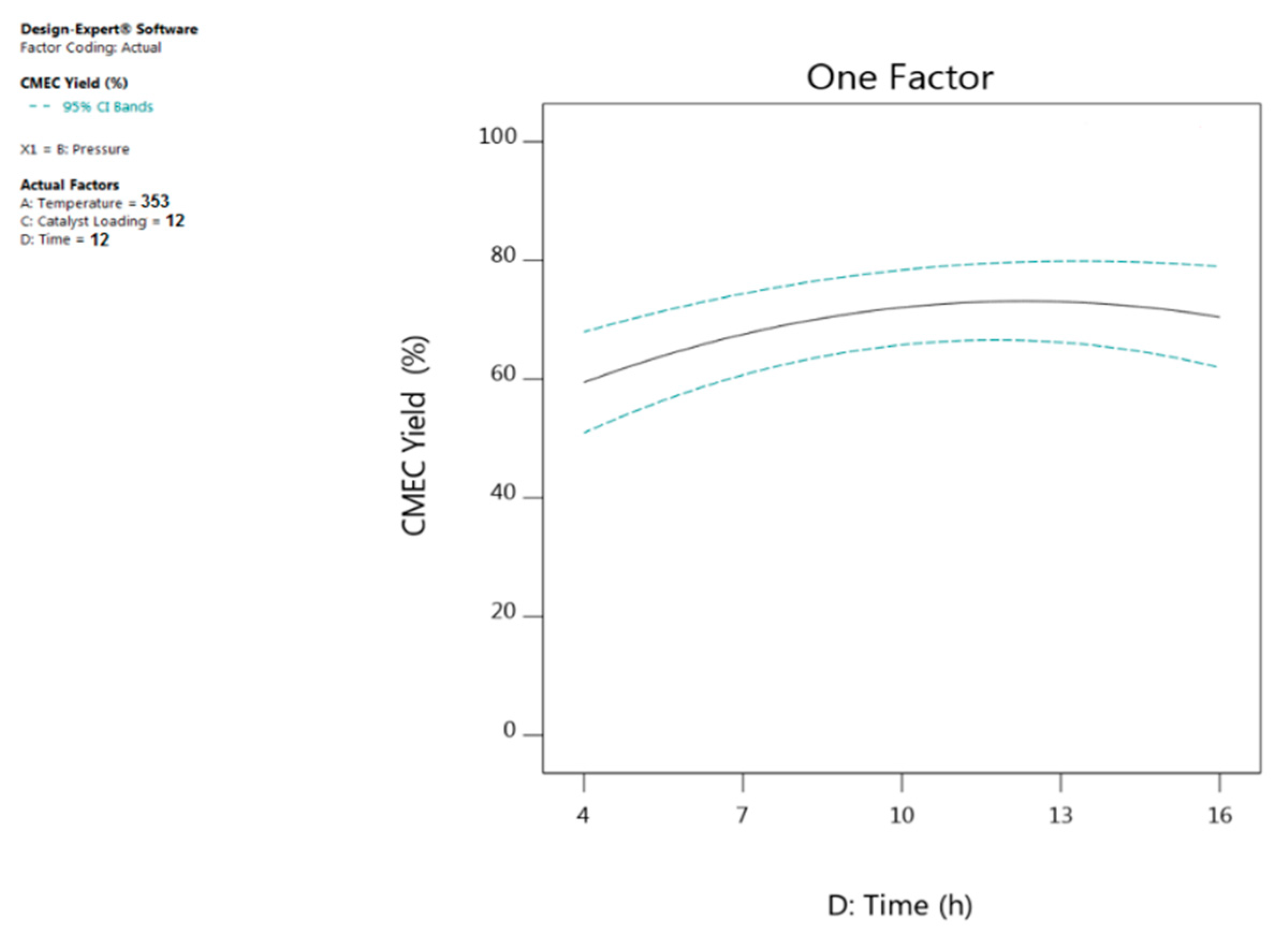
The effects of individual reaction variables (temperature, pressure, time, and catalyst loading) and their interactions on reaction responses (conversion and yield) have been investigated using the 3D-surface and 2D-contour plots generated from the predicted quadratic model as evidenced in Figure 6, Figure 7, Figure 8 and Figure 9. The experiments have been carried out by varying one reaction parameter at a time while keeping other parameters constant at the following reaction conditions: Reaction temperature 353 K, CO2 pressure 11 bar, reaction time 12 h, catalyst loading 12% (w/w).

4.1. Effect of Reaction Temperature

To a significant extent, it is largely agreed that a directly proportional relationship exists between temperature and CMEC yield as shown in the results of ANOVA in Table 4. The influence of reaction temperature on CMEC yield has been investigated by varying temperature over the range of 323 K to 373 K. As evidenced in Figure 6, CMEC yield increased steadily from 40% to 68% as temperature increased from 323 K to 353 K. However, a gradual decrease in CMEC yield was observed at higher temperature values beyond 353 K. This may be due to the formation of diols and dimers of epichlorohydrin above optimum temperature [57]. Saada et al. and co-workers explained that higher reaction temperatures caused a shift in the equilibrium to the reactant side and resulted in a reduced DMC yield. The same temperature effect was also reported by Kilic et al. [58]; they have observed that as they increased the reaction temperature from 348 K to 373 K (while keeping other variables constant), there was a corresponding increase in ECHC yield from 65.8% to 97.0%. However, further increase in temperature beyond 373 K, caused a slight decrease both in the ECHC yield and catalyst selectivity.

4.2. Effect of Carbon Dioxide (CO2) Pressure

ANOVA Table 4 demonstrates the dependence of CO2 pressure on CMEC yield, since CO2 acts both as reactant and reaction medium simultaneously [59]. As indicated in Figure 7, when CO2 pressure was increased from 8 to 11 bar, the CMEC yield also increased from 50% to 68%. Conversely, with the CO2 pressure of 11.5 bar, a 59% CMEC yield was recorded indicating a declining effect. Zhong et al. [60] demonstrated the effect of variation in CO2 pressure on organic carbonates. They have enhanced more propylene carbonate (PC) yield when CO2 pressure was increased from 1 MPa to 3 MPa. However, when CO2 pressure was further increased to 4 MPa, they observed that the concentration of propylene oxide (PO) in gas phase had decreased as a result of dilution by CO2 and consequently resulted in a reduced PC yield. It is therefore concluded that the optimum CO2 pressure based on OFAT analysis for this set of experiments was 11 bar of CO2 pressure.

4.3. Effect of Reaction Time

Reaction time is one of the crucial factors in a catalytic reaction. Figure 8 shows a direct proportionality effect between reaction time and the CMEC yield; the yield increased gradually as reaction time increased until it reached 68% in 12 h. Further increase in reaction time beyond 12 h resulted in a continuous decline in CMEC yield as shown in Figure 8. This could be as a result of formation of polymerized CMEC caused by prolonged reaction time [61]. A similar phenomenon was also reported by Onyenkeadi and co-workers, where increase in reaction time from 8 to 16 h was directly proportional to butylene carbonate (BC) yield. However, prolonged reaction time beyond this time resulted in decrease in BC yield.

4.4. Effect of Catalyst Loading

The effect of catalyst loading on CMEC yield was investigated by varying Zr/ZIF-8 loading from 5% to 15% (w/w). As shown in Figure 9, it can be observed that as catalyst loading was increased, CMEC yield also increased proportionally from 42% reaching a maximum of 68% at 12% (w/w) catalyst loading. It was then decreased progressively when the amount of catalyst was further increased to 13% (w/w), indicating that optimum catalyst loading had been exceeded. It would be expected that the number of active sites available for the reaction of ECH and CO2 would increase as catalyst loading increased [62]. However, Han et al. [63] argued that an excessive increase in catalyst loading tends to provoke formation of undesirable side-products (in their experiment, a by-product of diglyceride (GDL) or triglyceride (GTL) was formed), thereby causing a drop in glycerol monolaurate (GML) selectivity as they increased the amount of catalyst beyond 2% (w/w). Similarly, in the present work, increase in the amount of catalyst loading beyond the optimum level was unfavorable to the reactive system resulting in a reduced CMEC yield. Therefore, the optimum catalyst loading for this reactive system is 12% at a reaction temperature of 353 K for 12 h at 11 bar of CO2 pressure.

5. Interactive Effect of Process Variables on Responses

The interaction effect of each pair of reaction variables have been investigated using ANOVA results, 3D surface, and 2D contour plots. The interaction effect of some process variables on ECH conversion and CMEC yield produce different effects at different levels of other variables. Therefore, 3D plots have played a crucial role in making accurate predictions about process optimization [64]. From ANOVA Table 3 and Table 4, it can be observed that all the four reaction parameters are deemed significant and can affect the process response tremendously at different levels of interaction. Hence, the interactive effect of process variables has a direct influence on the system optimization. The interaction effect between a pair of variables would be negligible if the contour plot of the response surface is circular. Conversely, the interactions effect would be significant if the contour plot is elliptical [65]. Therefore, instead of studying single variable (as in conventional method) the interactions were investigated which is significant for a comprehensive optimization study.

5.1. Interactive Effect of Temperature and Pressure

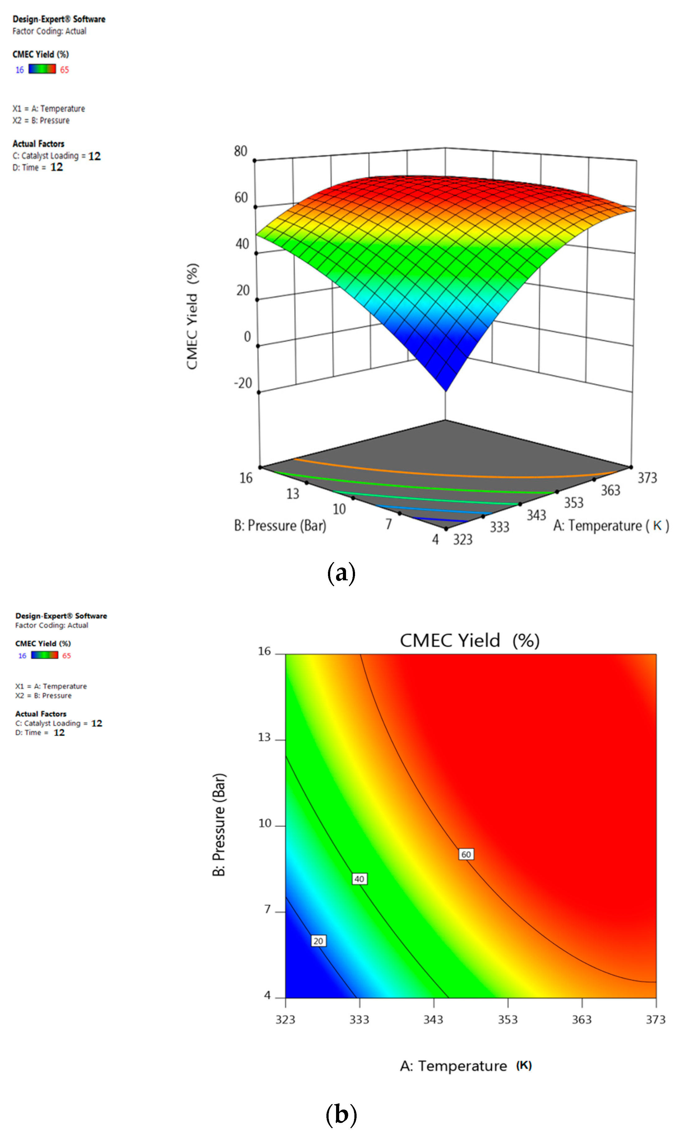
As depicted in Figure 10 and the ANOVA Table 3 and Table 4, the interaction effect of reaction temperature and CO2 pressure has played significant roles in both ECH conversion and CMEC yield (while keeping reaction time and catalyst loading at their optimum: 12 h and 12% (w/w), respectively). At lower reaction temperature (e.g., at 323 K), increase in the CO2 pressure from 4 to 16 bar increases the CMEC yield from 47% to 68%. However, higher reaction temperature beyond 353 K showed a negative effect on CMEC yield (Figure 10a); this could possibly be as a result of formation of by-products at elevated temperature as indicated in the reaction mechanism (Figure 1). Furthermore, at a different level of interaction between temperature and pressure (e.g., from 358 K to 373 K and 13–16 bar), a notable effect was also recorded where there was a gradual decline in the CMEC yield indicating optimum condition had been exceeded. This shows that variation in reaction temperature had a negative effect on both responses at higher values. Therefore, the temperature-pressure relationship has significant effect on process responses. Similarly, the elliptical shape of the 2D contour plot in Figure 10b exemplifies a mutual interactive effect of the reaction variables on responses.

5.2. Interactive Effect of Temperature and Time

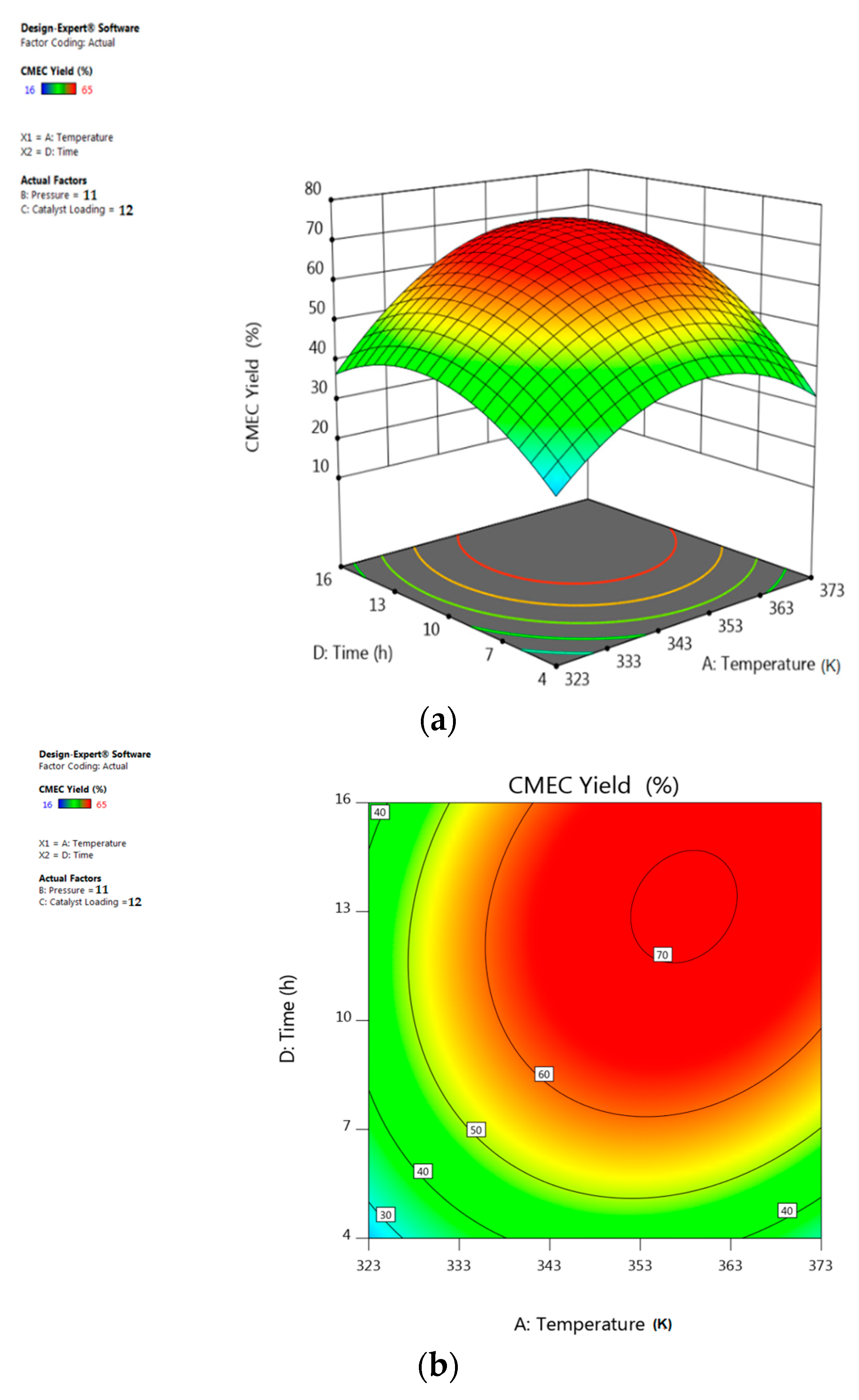
Figure 11 illustrates the interaction effect of reaction time and temperature on CMEC yield (while keeping other two variables at their optimum: Catalyst loading: 12% (w/w), CO2 pressure: 11 bar). The surface plot suggested that the CMEC yield was highest (68%) at a reaction time of 12 h and temperature of 353 K, indicating that an increase in the reaction temperature from 313 K to 353 K favors ECH conversion and consequently enhances CMEC yield as shown in Figure 11a. However, increase in reaction temperature beyond 353 K at 12 h of reaction time was unfavorable to the reactive system causing a marginal drop in CMEC yield from 68% to 65%. Onyenkeadi et al. and co-workers reported that formation of oligomers and isomers are possible at extended reaction time at higher temperature. Product quality and stability may also be affected due to chemical degradation or losses by thermal decomposition at higher reaction temperature [66]. Response surface and contour plots of Figure 11 clearly show that CMEC yield had a linear effect with increasing reaction temperature until the optimum condition was achieved. This phenomenon agrees with the Arrhenius law [67]; higher temperature results in a higher conversion rate and consequently leading to higher CMEC yield. It can be concluded from the ANOVA Table 4 that the reaction temperature was found to be a highly influencing parameter on both the conversion of ECH and CMEC yield as evident from low p-value (<0.0001).

5.3. Interactive Effect of Temperature and Catalyst Loading

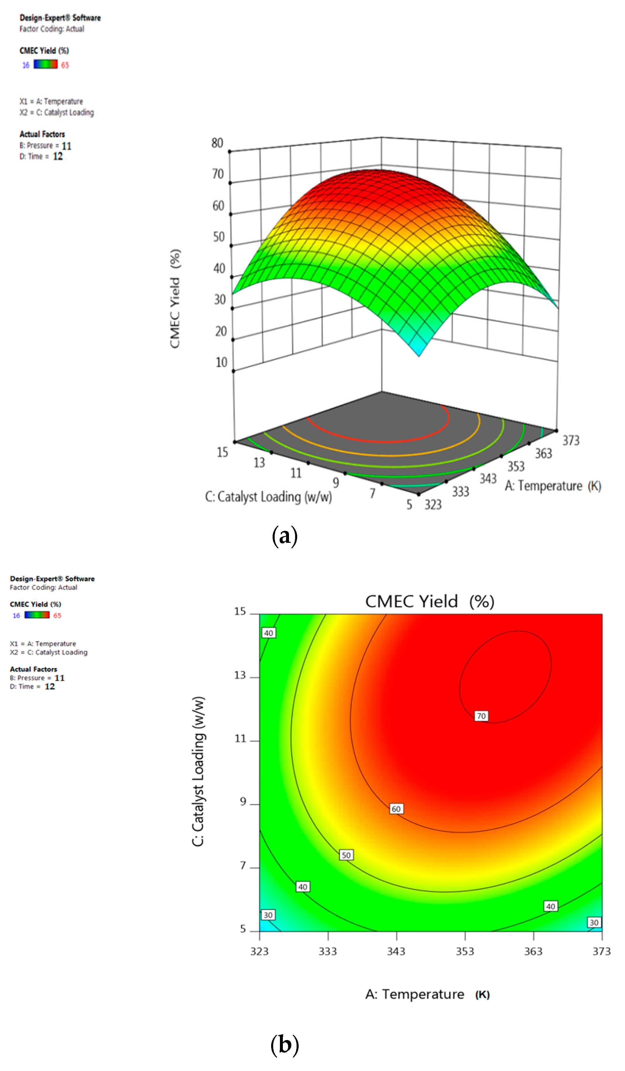
The overall CMEC yield has been significantly influenced by the interaction between the catalyst loading and reaction temperature while CO2 pressure and time have been kept at optimum values of 11 bar and 12 h, respectively. For example, Figure 11 shows that at lower catalyst loading of 5% (w/w), only 34% of CMEC yield was recorded as a result of low ECH conversion at low catalyst loading. The CMEC yield increased steadily up to 68% as reaction temperature increased at moderate levels of catalyst loading from 333 K to 353 K. This phenomenon could be attributed to the increase in the catalyst surface area, which provides more contact area between the limiting reactant ECH and the active sites of the catalyst. Higher catalyst loading gives higher ECH conversion resulting in higher CMEC yield—an effect which is more pronounced at higher temperatures. However, at higher temperature above 353 K, a marginal decrease in CMEC yield was observed, which may be due to catalyst deactivation at very high temperature [68]. The contour plot in Figure 12b with elliptical shape demonstrated the significant and combined effect of the catalyst loading and reaction temperature. The result has also supported lower p-value (0.0005) of the interaction x1x3 term. As shown in Figure 12a, at any designated value of reaction temperature from 333 K to 353 K, the CMEC increased proportionally with catalyst loading. This observation was also supported by low p-value (<0.0001).

5.4. Interactive Effect of Time and Pressure

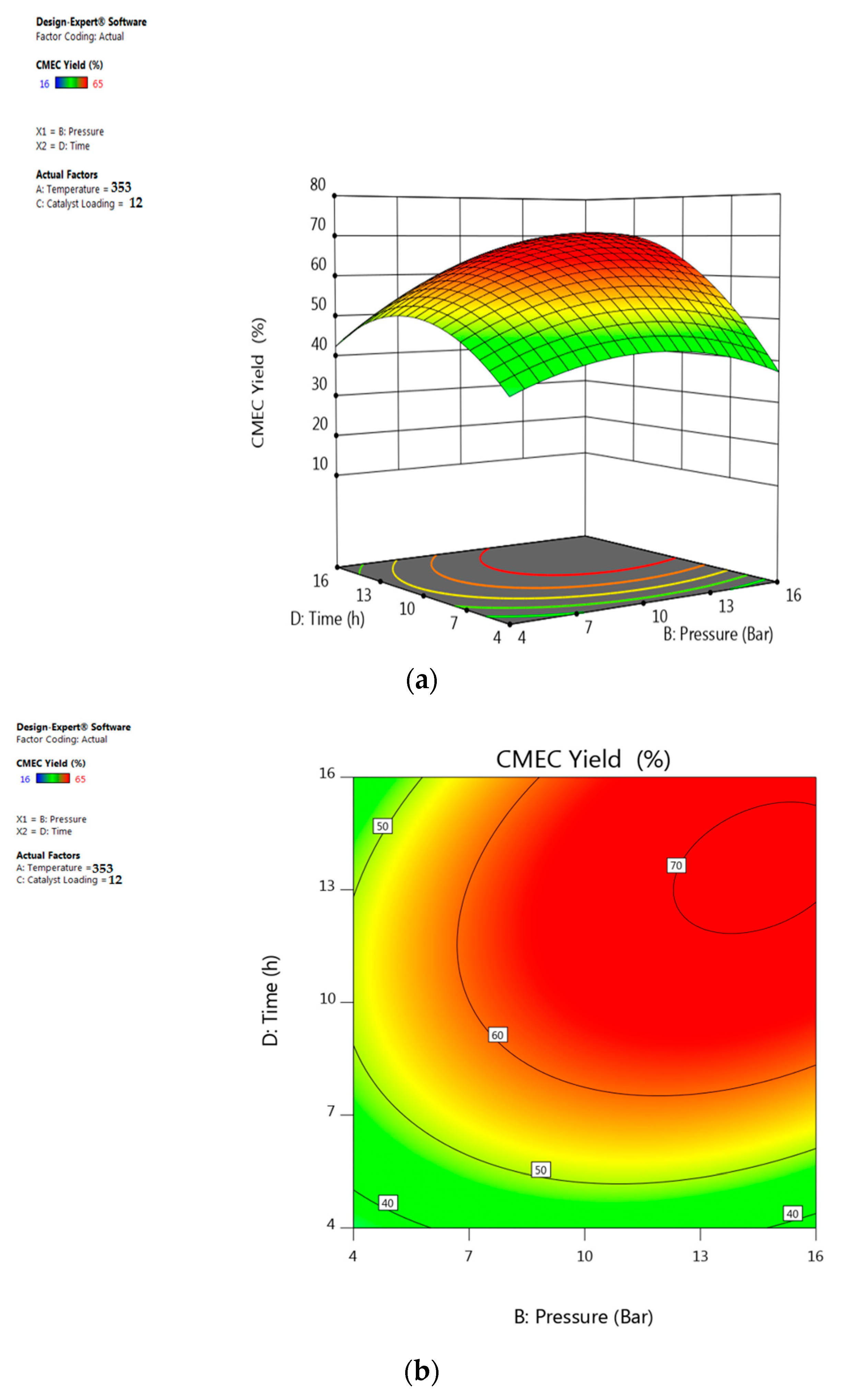
Similar to the previous observation of the interaction effect of temperature and pressure, Figure 13 demonstrates the interaction effect of CO2 pressure and time on CMEC yield while maintaining reaction temperature and catalyst loading at 353 K and 12% (w/w), respectively. For example, at a shorter reaction time of 4 h, there was a negligible effect of CO2 pressure in the CMEC yield. Figure 13a shows that optimum reaction time of 12 h was observed at a CO2 pressure of about 12 bar with a 68% of CMEC yield. It has been observed in Figure 13 that the CMEC yield reached a maximum at a reaction time of 12 h, thereafter, it was stable. A further increase in reaction time beyond this value caused a sharp drop in CMEC yield as indicated in surface plot of Figure 13b.

5.5. Interactive Effect of Time and Catalyst Loading

The contour and 3D surface plots in Figure 14 show the interaction effect between the reaction time and the catalyst loading at a constant temperature of 353 K and CO2 pressure of 12 bar. The contour plots show less curvature up to 7 h of reaction time, which implied less influence of catalyst loading on CMEC yield between the reaction time of 2 to 6 h. However, a maximum CMEC yield of 68% was achieved at higher catalyst loading and reaction time of 12% (w/w) and 12 h, respectively. A declining effect was observed in Figure 14a as the catalyst loading goes above 12% (w/w). This reflects that the optimum catalyst loading had been exceeded. A similar trend was reported by Onyenkeadi and research team on declining effect of catalyst loading beyond the optimum reaction time. Increase in the amount of catalyst loading can increase the number of active sites on the catalyst surface, and consequently, increases number of radicals (see supplementary information sheet, Figure S1). However, excessive increase of catalyst concentration beyond the optimum reaction time can result in a catalyst deactivation. This phenomenon is totally in agreement with the recent reports of Feilizadeh et al. [69].

5.6. Interactive Effect of Catalyst Loading and Pressure

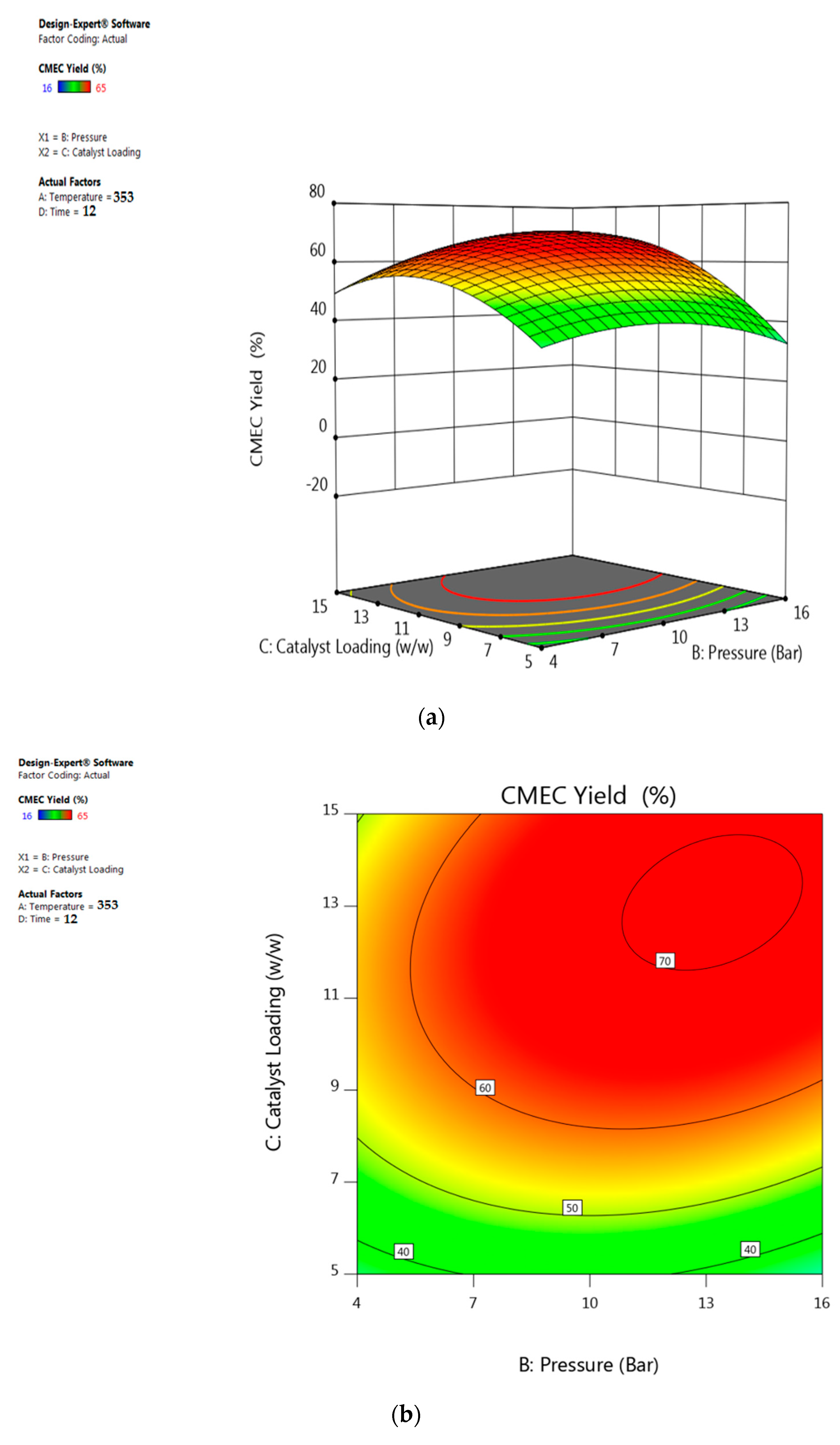
The exponential interaction effect between catalyst loading and pressure at a constant reaction time of 12 h and a temperature of 353 K is presented in Figure 15. However, the interaction produced a different effect on CMEC yield at different levels of interaction (i.e., different levels of interaction produce different effects on the ECH conversion). For example, Figure 15 shows that at the start of the reaction, 5% (w/w) of catalyst loading at 7 bar of CO2 pressure produced an increasing effect on the CMEC yield. As the catalyst loading was further increased from 5% to 10% (w/w), the CMEC yield was observed to increase steadily from 40% to 68% corresponding to an increase in CO2 pressure from 7 to 11 bar. The CMEC yield was highest (68%) at a maximum catalyst loading of 12 % (w/w), when the CO2 pressure was maintained at 11 bar as shown in Figure 15. However, a negative effect of excessive increase in CO2 pressure was observed on CMEC yield (a drop to 64%) at this level of interaction between catalyst loading and pressure. This phenomenon can be attributed to catalyst deactivation at increased CO2 pressure beyond the optimum. A similar experience was reported earlier by Zhang et al. [70]. The group have recorded a higher propylene carbonate (PC) yield with a fixed amount of immobilized ionic liquid/ZnCl2 at a CO2 pressure of 1.5 MPa, however, a lower PC yield was observed at a higher CO2 pressure of 2 MPa. Furthermore, they claimed that this phenomenon occurs when acidic CO2 dissolves in basic epoxide to form a liquefied CO2−epoxide complex, thereby inducing catalyst deactivation.

6. Multiobjective Process Optimization

The growing quest for greener substitute for fossil fuel has led to increased production, process optimization, and application of organic carbonate. As a result, the use of RSM has received more attention over conventional optimization methods in order to investigate process optimum conditions and the interactive relationships between effective working variables. Although, finding the optimal reaction parameters for a single response using RSM is relatively simple; however, the optimization of several responses at the same time is not an easy matter. Table 5 shows the optimization targets for this study, the values have been set to maximize the process productivity. Targets for both ECH conversion and CMEC yield have been set to reach the maximum values while both the reaction temperature and time have been targeted to minimum values with a viewpoint of reducing production cost at a maximum economic gain. Because of the catalyst efficiency and stability at optimum conditions, as a result, no specific target has been set for catalyst loading.
Based on the models generated and the accuracy between the actual experimental and predicted results, it can be construed that the model shows high consistencies between the two results where the relative errors of the predicted results from the experimental data are 1.55% and 1.54% for ECH conversion and CMEC yield, respectively. The similarity between the predicted and experimental results at the optimum conditions has validated the predicted optimum conditions. The experimental results concluded that increase in reaction parameters increases ECH conversion and CMEC yield being 93% and 68%, respectively.

7. Catalyst Reusability Studies

In view of large scale industrial applications and to minimize production cost, the reusability studies of Zr/ZIF-8 catalyst have been investigated. The catalyst reusability process has also followed strict eco-regulation after all the predicted optimum parameters have been derived from BBD of RSM. The experiments were carried out in a high-pressure reactor at optimum reaction conditions, at 353 K, 11 bar with fresh 12% (w/w) ZIF-8 catalyst loading, for 12 h, and at a stirring speed of 350 rpm. The catalyst after Run 1 in the cycloaddition reaction was washed with ethanol and acetone, centrifuged, and oven dried at 343 K for 12 h before reuse. The recovered catalysts were reused for up to seven subsequent experiments as shown in Figure 16, following the same experimental procedure. The catalyst exhibited no loss of activity indicating the catalyst stability for cycloaddition reaction of CO2 epichlorohydrin. Incorporating zirconium into ZIF-8 has significantly increased the catalytic performance of Zr/ZIF-8 with the conversion of ECH and the yield of CMEC being 93% and 68%, respectively. The activity of reused Zr/ZIF-8 catalyst showed consistent stability over seven subsequent runs as indicated in Figure 16. Although, a very slight decrease in the yield of CMEC from 68% (fresh) to 67% (recycled) was observed in the seventh run. Carbonaceous material formed during the reaction may explain in part the lower activity of the recycled catalysts [71].
Although, the difference in the error bars status between the ECH conversion and CMEC yield may be statistically significant, this may be attributed to the formation of some side products associated with the coupling reaction of CO2 and ECH. The following side products have been identified by the GC analysis; 3-chloropropane 1,2-diol and 2,5-bis (chloromethyl)-1,4-dioxane.

8. Conclusions

In this study, Zr/ZIF-8 catalyst has been successfully used for process optimization in the synthesis of CMEC using RSM. In total, 29 runs of experiments were conducted for optimum design and modelling. The developed model was validated to assess the agreement between its predictions and a set of experimental data. The development of a novel Zr/ZIF-8 catalyst via a simple low cost solvothermal method has demonstrated that the catalyst is viable for large-scale industrial applications. The catalyst has shown a good substrate tolerance as demonstrated by its activity towards epichlorohydrin. More importantly, the reaction has been carried out under solvent free and co-catalyst free conditions. The heterogeneity of the catalyst has been proven by recovering and reusing the catalyst for up to seven times without any significant loss in catalytic activity. Furthermore, PXRD, FT-IR, and TGA analysis (see supplementary information sheets, S2, S3 and S4) of the recycled catalyst shows that the catalyst framework is quite stable after recycled experiments. The high selectivity towards epichlorohydrin carbonate, simple separation of catalyst by centrifugation, and excellent recyclability demonstrated that the catalyst is viable for industrial applications. We believe that this work could provide a new direction for designing more sustainable heterogeneous catalysts for greener synthesis of organic carbonates via CO2 utilization.

Supplementary Materials

The following are available online at https://www.mdpi.com/1996-1073/13/3/741/s1, Figure S1: Proposed free radical mechanism for cycloaddition reaction of CO2 and ECH, Figure S2: X-ray diffraction (XRD) patterns of (a) ZIF-8, (b) Zr/ZIF-8 and (c) recycled Zr/ZIF-8 catalysts, Figure S3: FTIR spectra of (a) ZIF-8, (b) Zr/ZIF-8 and (c) recycled Zr/ZIF-8 particles, Figure S4: Thermal stability curve of (a) ZIF-8 and (b) Zr/ZIF-8.

Author Contributions

B.O.: main author and prepared the original draft. B.S.: Reviewed manuscript, gave comments, edited contents and supervised B.O. All authors have read and agreed to the published version of the manuscript.

Funding

This research received no external funding.

Acknowledgments

Bisi Olaniyan is immensely grateful to the School of Engineering, LSBU, UK for partial financial assistance rendered throughout this research work.

Conflicts of Interest

The authors declare no conflict of interest.

References

  1. Miao, C.-X.; Wang, J.-Q.; He, L.-N. Catalytic Processes for Chemical Conversion of Carbon Dioxide into Cyclic Carbonates and Polycarbonates. Open Org. Chem. J. 2008, 2, 68–82. [Google Scholar] [CrossRef] [Green Version]
  2. Liu, B.; Liu, M.; Liang, L.; Sun, J. Guanidine Hydrochloride/ZnI2 as Heterogeneous Catalyst for Conversion of CO2 and Epoxides to Cyclic Carbonates under Mild Conditions. Catalysts 2015, 5, 119–130. [Google Scholar] [CrossRef] [Green Version]
  3. Xie, Y.; Wang, T.-T.; Liu, X.-H.; Zou, K.; Deng, W.-Q. Capture and conversion of CO2 at ambient conditions by a conjugated microporous polymer. Nat. Commun. 2013, 4, 1960–1967. [Google Scholar] [CrossRef] [PubMed] [Green Version]
  4. North, M.; Pasquale, R.; Young, C. Synthesis of cyclic carbonates from epoxides and CO2. Green Chem. 2010, 12, 1514–1539. [Google Scholar] [CrossRef]
  5. Sathe, A.A.; Nambiar, A.M.; Sturgis, N.; Rioux, M. Synthesis of cyclic organic carbonates via catalytic oxidative carboxylation of olefins in flow reactors. Catal. Sci. Technol. 2017, 7, 2–3. [Google Scholar] [CrossRef]
  6. Liu, A.-H.; Li, Y.-N.; He, L.-N. Organic synthesis using carbon dioxide as phosgene-free carbonyl reagent. Pure Appl. Chem. 2012, 84, 581–602. [Google Scholar] [CrossRef]
  7. Maeda, C.; Miyazaki, Y.; Ema, T. Recent progress in catalytic conversions of carbon dioxide. Catal. Sci. Technol. 2014, 4, 74–82. [Google Scholar] [CrossRef] [Green Version]
  8. Adeleye, A.I.; Kellici, S.; Heil, T.; Morgan, D.; Vickers, M.; Saha, B. Greener synthesis of propylene carbonate using graphene-inorganic nanocomposite catalysts. Catal. Today 2015, 256, 347–357. [Google Scholar] [CrossRef]
  9. Onyenkeadi, V.; Kellici, S.; Saha, B. Greener synthesis of 1,2-butylene carbonate from CO2 using graphene-inorganic nanocomposite catalyst. Energy 2018, 165, 867–876. [Google Scholar] [CrossRef]
  10. Adeleye, A.I.; Patel, D.; Niyogi, D.; Saha, B. Efficient and greener synthesis of propylene carbonate from carbon dioxide and propylene oxide. Ind. Eng. Chem. Res. 2014, 53, 18647–18657. [Google Scholar] [CrossRef]
  11. Sakakura, T.; Kohno, K. The synthesis of organic carbonates from carbon dioxide. Chem. Commun. 2009, 10, 1312–1330. [Google Scholar] [CrossRef] [PubMed]
  12. Shukla, K.; Srivastava, V.C. Synthesis of organic carbonates from alcoholysis of urea: A review. Catal. Rev. Sci. Eng. 2017, 59, 1–43. [Google Scholar] [CrossRef]
  13. Dalpozzo, R.; Ca, N.D.; Gabriele, B.; Mancuso, R. Recent advances in the chemical fixation of carbon dioxide: A green route to carbonylated heterocycle synthesis. Catalysts 2019, 9, 511. [Google Scholar] [CrossRef] [Green Version]
  14. Lu, X.B.; Liang, B.; Zhang, Y.J.; Tian, Y.Z.; Wang, Y.M.; Bai, C.X.; Wang, H.; Zhang, R. Asymmetric Catalysis with CO2: Direct Synthesis of Optically Active Propylene Carbonate from Racemic Epoxides. J. Am. Chem. Soc. 2004, 126, 3732–3733. [Google Scholar] [CrossRef]
  15. Paddock, R.L.; Nguyen, S.T. Chemical CO2 fixation: CR(III) salen complexes as highly efficient catalysts for the coupling of CO2 and epoxides. J. Am. Chem. Soc. 2001, 123, 11498–11499. [Google Scholar] [CrossRef]
  16. Caló, V.; Nacci, A.; Monopoli, A.; Fanizzi, A. Cyclic carbonate formation from carbon dioxide and oxiranes in tetrabutylammonium halides as solvents and catalysts. Org. Lett. 2002, 4, 2561–2563. [Google Scholar] [CrossRef]
  17. He, Q.; O’Brien, J.W.; Kitselman, K.A.; Tompkins, L.E.; Curtis, G.C.T.; Kerton, F.M. Synthesis of cyclic carbonates from CO2 and epoxides using ionic liquids and related catalysts including choline chloride-metal halide mixtures. Catal. Sci. Technol. 2014, 4, 1513–1528. [Google Scholar] [CrossRef]
  18. Olaniyan, B.; Saha, B. Comparison of Catalytic Activity of ZIF-8 and Zr/ZIF-8 for Greener Synthesis of Chloromethyl Ethylene Carbonate by CO2 Utilization. Energies 2020, 13, 521. [Google Scholar] [CrossRef] [Green Version]
  19. Kihara, N.; Hara, N.; Endo, T. Catalytic Activity of Various Salts in the Reaction of 2,3-Epoxypropyl Phenyl Ether and Carbon Dioxide under Atmospheric Pressure. J. Org. Chem. 1993, 58, 6198–6202. [Google Scholar] [CrossRef]
  20. Castro-Osma, J.A.; Lamb, K.J.; North, M. Cr(salophen) Complex Catalyzed Cyclic Carbonate Synthesis at Ambient Temperature and Pressure. ACS Catal. 2016, 6, 5012–5025. [Google Scholar] [CrossRef]
  21. Rulev, Y.A.; Larionov, V.A.; Lokutova, A.V.; Moskalenko, M.A.; Lependina, O.L.; Maleev, V.I.; North, M.; Belokon, Y.N. Chiral Cobalt(III) Complexes as Bifunctional Brønsted Acid-Lewis Base Catalysts for the Preparation of Cyclic Organic Carbonates. ChemSusChem 2016, 9, 216–222. [Google Scholar] [CrossRef] [PubMed]
  22. Jutz, F.; Grunwaldt, J.D.; Baiker, A. Mn(III)(salen)-catalyzed synthesis of cyclic organic carbonates from propylene and styrene oxide in ‘supercritical’ CO2. J. Mol. Catal. A Chem. 2008, 279, 94–103. [Google Scholar] [CrossRef]
  23. Kuznetsova, S.A.; Rulev, Y.A.; Larionov, V.A.; Smol’yakov, A.F.; Zubavichus, Y.V.; Maleev, V.I.; Li, H.; North, M.; Saghyan, A.S.; Belokon, Y.N. Self-Assembled Ionic Composites of Negatively Charged Zn(salen) Complexes and Triphenylmethane Derived Polycations as Recyclable Catalysts for the Addition of Carbon Dioxide to Epoxides. ChemCatChem 2019, 11, 511–519. [Google Scholar] [CrossRef]
  24. Luo, R.; Zhou, X. Metal- and solvent-free synthesis of cyclic carbonates from epoxides and CO2 in the presence of graphite oxide and ionic liquid under mild conditions: A kinetic study. Carbon 2014, 82, 1–11. [Google Scholar] [CrossRef]
  25. Siewniak, A.; Jasiak, K.; Baj, S. An efficient method for the synthesis of cyclic carbonates from CO2 and epoxides using an effective two-component catalyst system: Polymer-supported quaternary onium salts and aqueous solutions of metal salts. Appl. Catal. A Gen. 2014, 482, 266–274. [Google Scholar] [CrossRef]
  26. Ma, D.; Li, B.; Liu, K.; Zhang, X.; Zou, W.; Yang, Y.; Li, G.; Shi, Z.; Feng, S. Bifunctional MOF heterogeneous catalysts based on the synergy of dual functional sites for efficient conversion of CO2 under mild and co-catalyst free conditions. J. Mater. Chem. A 2015, 3, 23136–23142. [Google Scholar] [CrossRef]
  27. Saptal, V.B.; Bhanage, B.M. Current advances in heterogeneous catalysts for the synthesis of cyclic carbonates from carbon dioxide. Curr. Opin. Green Sustain. Chem. 2017, 3, 1–10. [Google Scholar] [CrossRef]
  28. Adeleye, A.I. (Supervisor-Saha. B) Heterogeneous Catalytic Conversion of Carbon Dioxide to Value Added Chemicals. Ph.D. Thesis, London South Bank University, London, UK, 2015. [Google Scholar]
  29. Zalomaeva, O.V.; Chibiryaev, A.M.; Kovalenko, K.A.; Kholdeeva, O.A.; Balzhinimaev, B.S.; Fedin, V.P. Cyclic carbonates synthesis from epoxides and CO2 over metal-organic framework Cr-MIL-101. J. Catal. 2013, 298, 179–185. [Google Scholar] [CrossRef]
  30. Beyzavi, M.H.; Stephenson, C.J.; Liu, Y.; Karagiaridi, O.; Hupp, J.T.; Farha, O.K. Metal Organic Framework-Based Catalysts: Chemical Fixation of CO2 with Epoxides Leading to Cyclic Organic Carbonates. Front. Energy Res. 2015, 2, 1–10. [Google Scholar] [CrossRef] [Green Version]
  31. Li, Q.; Yang, W.; Li, F.; Cui, A.; Hong, J. Preparation of CoB/ZIF-8 supported catalyst by single step reduction and its activity in hydrogen production. Int. J. Hydrogen Energy 2018, 43, 271–282. [Google Scholar] [CrossRef]
  32. Jumbri, K.; Al-Haniff Rozy, M.F.; Ashari, S.E.; Mohamad, R.; Basri, M.; Fard Masoumi, H.R. Optimisation and characterisation of lipase catalysed synthesis of a kojic monooleate ester in a solvent-free system by response surface methodology. PLoS ONE 2015, 10, 1–13. [Google Scholar] [CrossRef] [PubMed]
  33. Koech, J.K.; Mutiso, M.J.; Koskei, J.K. Response Surface Methodology Approach to the Optimization of Potato (Solanum tuberosum) Tuber Yield Using Second-Order Rotatable Design. J. Biom. Biostat. 2017, 8, 22–33. [Google Scholar]
  34. Manohar, M.; Joseph, J.; Selvaraj, T.; Sivakumar, D. Application of box Behnken design to optimize the parameters for turning inconel 718 using coated carbide tools. Int. J. Sci. Eng. Res. 2013, 4, 620–642. [Google Scholar]
  35. Jeirani, Z.; Mohamed Jan, B.; Si Ali, B.; Mohd Noor, I.; Chun Hwa, S.; Saphanuchart, W. The optimal mixture design of experiments: Alternative method in optimizing the aqueous phase composition of a microemulsion. Chemom. Intell. Lab. Syst. 2012, 112, 1–7. [Google Scholar] [CrossRef]
  36. Khuri, A.I.; Mukhopadhyay, S. Response surface methodology. Wiley Interdiscip. Rev. Comput. Stat. 2010, 2, 128–149. [Google Scholar] [CrossRef]
  37. Saada, R.; AboElazayem, O.; Kellici, S.; Heil, T.; Morgan, D.; Lampronti, G.I.; Saha, B. Greener synthesis of dimethyl carbonate using a novel tin-zirconia/graphene nanocomposite catalyst. Appl. Catal. B Environ. 2018, 226, 451–462. [Google Scholar] [CrossRef] [Green Version]
  38. Aboelazayem, O.; El-Gendy, N.S.; Abdel-Rehim, A.A.; Ashour, F.; Sadek, M.A. Biodiesel production from castor oil in Egypt: Process optimisation, kinetic study, diesel engine performance and exhaust emissions analysis. Energy 2018, 157, 843–852. [Google Scholar] [CrossRef]
  39. Onyenkeadi, V.; Aboelazayem, O.; Saha, B. Systematic multivariate optimisation of butylene carbonate synthesis via CO2 utilisation using graphene-inorganic nanocomposite catalysts. Catal. Today 2019, 7, 1–13. [Google Scholar] [CrossRef]
  40. Kumar, A.; Gupta, M.; Mazumder, A.; Poluri, K.M.; Rao, V.K. Use of Box Behnken Design for Development of High Throughput Quantitative Proton Nuclear Magnetic Resonance Experiments for Industrial Applications. Ind. Eng. Chem. Res. 2017, 56, 2873–2882. [Google Scholar] [CrossRef]
  41. Sadeghi, N.; Sharifnia, S.; Do, T.O. Optimization and modeling of CO2 photoconversion using a response surface methodology with porphyrin-based metal organic framework. React. Kinet. Mech. Catal. 2018, 125, 411–431. [Google Scholar] [CrossRef]
  42. Yu, X.L.; He, Y. Application of Box-Behnken designs in parameters optimization of differential pulse anodic stripping voltammetry for lead(II) determination in two electrolytes. Sci. Rep. 2017, 7, 1–8. [Google Scholar] [CrossRef] [PubMed] [Green Version]
  43. Yuan, J.; Huang, J.; Wu, G.; Tong, J.; Xie, G.; Duan, J.A.; Qin, M. Multiple responses optimization of ultrasonic-assisted extraction by response surface methodology (RSM) for rapid analysis of bioactive compounds in the flower head of Chrysanthemum morifolium Ramat. Ind. Crops Prod. 2015, 74, 192–199. [Google Scholar] [CrossRef]
  44. Nwabueze, T.U. Basic steps in adapting response surface methodology as mathematical modelling for bioprocess optimisation in the food systems. Int. J. Food Sci. Technol. 2010, 45, 1768–1776. [Google Scholar] [CrossRef]
  45. Mostafaei, M.; Ghobadian, B.; Barzegar, M.; Banakar, A. Optimization of ultrasonic assisted continuous production of biodiesel using response surface methodology. Ultrason. Sonochem. 2015, 27, 54–61. [Google Scholar] [CrossRef]
  46. Schejn, A.; Aboulaich, A.; Balan, L.; Falk, V.; Lalevée, J.; Medjahdi, G.; Aranda, L.; Mozet, K.; Schneider, R. Cu2+ -doped zeolitic imidazolate frameworks (ZIF-8): Efficient and stable catalysts for cycloadditions and condensation reactions. Catal. Sci. Technol. 2015, 5, 1829–1839. [Google Scholar] [CrossRef]
  47. Thi Thanh, M.; Vinh Thien, T.; Thi Thanh Chau, V.; Dinh Du, P.; Phi Hung, N.; Quang Khieu, D. Synthesis of Iron Doped Zeolite Imidazolate Framework-8 and Its Remazol Deep Black RGB Dye Adsorption Ability. J. Chem. 2017, 8, 635–650. [Google Scholar] [CrossRef] [Green Version]
  48. Zhou, K.; Mousavi, B.; Luo, Z.; Phatanasri, S.; Chaemchuen, S.; Verpoort, F. Characterization and properties of Zn/Co zeolitic imidazolate frameworks vs. ZIF-8 and ZIF-67. J. Mater. Chem. A 2017, 5, 952–957. [Google Scholar] [CrossRef]
  49. Saada, R. (Supervisor-Saha. B) Catalytic Conversion of Carbon Dioxide (CO2) into Value Added Chemicals. Ph.D. Thesis, London South Bank University, London, UK, 2015. [Google Scholar]
  50. Gallardo-Fuentes, S.; Contreras, R.; Isaacs, M.; Honores, J.; Quezada, D.; Landaeta, E.; Ormazábal-Toledo, R. On the mechanism of CO2 electro-cycloaddition to propylene oxides. J. CO2 Util. 2016, 16, 114–120. [Google Scholar] [CrossRef]
  51. Liu, Y.; Liu, F.; Ni, L.; Meng, M.; Meng, X.; Zhong, G.; Qiu, J. A modeling study by response surface methodology (RSM) on Sr(II) ion dynamic adsorption optimization using a novel magnetic ion imprinted polymer. RSC Adv. 2016, 6, 54679–54692. [Google Scholar] [CrossRef]
  52. Mäkelä, M. Experimental design and response surface methodology in energy applications: A tutorial review. Energy Convers. Manag. 2017, 151, 630–640. [Google Scholar] [CrossRef]
  53. Zhu, Z.; Rosendahl, L.; Toor, S.S.; Chen, G. Optimizing the conditions for hydrothermal liquefaction of barley straw for bio-crude oil production using response surface methodology. Sci. Total Environ. 2018, 630, 560–569. [Google Scholar] [CrossRef] [PubMed]
  54. Lee, D.W.; Marasini, N.; Poudel, B.K.; Kim, J.H.; Cho, H.J.; Moon, B.K.; Choi, H.G.; Yong, C.S.; Kim, J.O. Application of Box-Behnken design in the preparation and optimization of fenofibrate-loaded self-microemulsifying drug delivery system (SMEDDS). J. Microencapsul. 2014, 31, 31–40. [Google Scholar] [CrossRef] [PubMed]
  55. Rabiee, F.; Mahanpoor, K. Catalytic oxidation of SO2 by novel Mn/copper slag nanocatalyst and optimization by Box-Behnken design. Int. J. Ind. Chem. 2018, 9, 27–38. [Google Scholar] [CrossRef] [Green Version]
  56. Long, X.; Cai, L.; Li, W. RSM-based assessment of pavement concrete mechanical properties under joint action of corrosion, fatigue, and fiber content. Constr. Build. Mater. 2019, 197, 406–420. [Google Scholar] [CrossRef]
  57. Mohammadifard, H.; Amiri, M.C. On tailored synthesis of nano CaCO3 particles in a colloidal gas aphron system and evaluating their performance with response surface methodology for heavy metals removal from aqueous solutions. J. Water Environ. Nanotechnol. 2018, 3, 141–149. [Google Scholar]
  58. Kilic, A.; Durgun, M.; Aytar, E.; Yavuz, R. Synthesis and characterization of novel positively charged organocobaloximes as catalysts for the fi xation of CO2 to cyclic carbonates. J. Organomet. Chem. 2018, 858, 78–88. [Google Scholar] [CrossRef]
  59. Abhang, R.M.; Wani, K.S.; Patil, V.S. Synthesis and Characterization of ZIF-8 Filler for preparation of Mixed Matrix Membrane. Int. J. Sci. Eng. Res. 2015, 6, 1276–1280. [Google Scholar]
  60. Zhong, S.; Liang, L.; Liu, B.; Sun, J. ZnBr2/DMF as simple and highly active Lewis acid–base catalysts for the cycloaddition of CO2 to propylene oxide. J. CO2 Util. 2014, 6, 75–79. [Google Scholar] [CrossRef]
  61. Shi, J.; Song, J.; Ma, J.; Zhang, Z.; Fan, H.; Han, B. Effective synthesis of cyclic carbonates from CO2 and epoxides catalyzed by KI/cucurbit[6]uril. Pure Appl. Chem. 2013, 85, 1633–1641. [Google Scholar] [CrossRef]
  62. Xuan, K.; Pu, Y.; Li, F.; Li, A.; Luo, J.; Li, L.; Wang, F.; Zhao, N. Direct synthesis of dimethyl carbonate from CO2 and methanol over tri fl uoroacetic acid modulated UiO-66. J. CO2 Util. 2018, 27, 272–282. [Google Scholar] [CrossRef]
  63. Han, X.; Zhu, G.; Ding, Y.; Miao, Y.; Wang, K.; Zhang, H.; Wang, Y.; Liu, S. Bin Selective catalytic synthesis of glycerol monolaurate over silica gel-based sulfonic acid functionalized ionic liquid catalysts. Chem. Eng. J. 2019, 359, 733–745. [Google Scholar] [CrossRef]
  64. Bahrami, M.; Amiri, M.J.; Bagheri, F. Optimization of the lead removal from aqueous solution using two starch based adsorbents: Design of experiments using response surface methodology (RSM). J. Environ. Chem. Eng. 2019, 7, 700–793. [Google Scholar] [CrossRef]
  65. Nandiwale, K.Y.; Bokade, V.V. Process optimization by response surface methodology and kinetic modeling for synthesis of methyl oleate biodiesel over H3PW12O40 anchored montmorillonite K10. Ind. Eng. Chem. Res. 2014, 53, 18690–18698. [Google Scholar] [CrossRef]
  66. Peng, J.; Wang, S.; Yang, H.; Ban, B.; Wei, Z.; Wang, L.; Lei, B. Highly e ffi cient fi xation of carbon dioxide to cyclic carbonates with new multi-hydroxyl bis- (quaternary ammonium ) ionic liquids as metal-free catalysts under mild conditions. Fuel 2018, 224, 481–488. [Google Scholar] [CrossRef]
  67. Baş, D.; Boyacı, İ.H. Modeling and optimization I: Usability of response surface methodology. J. Food Eng. 2007, 78, 836–845. [Google Scholar] [CrossRef]
  68. Bezerra, M.A.; Santelli, R.E.; Oliveira, E.P.; Villar, L.S.; Escaleira, L.A. Response surface methodology (RSM) as a tool for optimization in analytical chemistry. Talanta 2008, 76, 965–977. [Google Scholar] [CrossRef]
  69. Feilizadeh, M.; Rahimi, M.; Zakeri, S.M.E.; Mahinpey, N.; Vossoughi, M.; Qanbarzadeh, M. Individual and interaction effects of operating parameters on the photocatalytic degradation under visible light illumination: Response surface methodological approach. Can. J. Chem. Eng. 2017, 95, 1228–1235. [Google Scholar] [CrossRef]
  70. Zhang, Y.; Yin, S.; Luo, S.; Au, C.T. Cycloaddition of CO2 to epoxides catalyzed by carboxyl-functionalized imidazolium-based ionic liquid grafted onto cross-linked polymer. Ind. Eng. Chem. Res. 2012, 51, 3951–3957. [Google Scholar] [CrossRef]
  71. Bosch, M.; Zhang, M.; Zhou, H.-C. Increasing the Stability of Metal-Organic Frameworks. Adv. Chem. 2014, 2014, 1–8. [Google Scholar] [CrossRef]
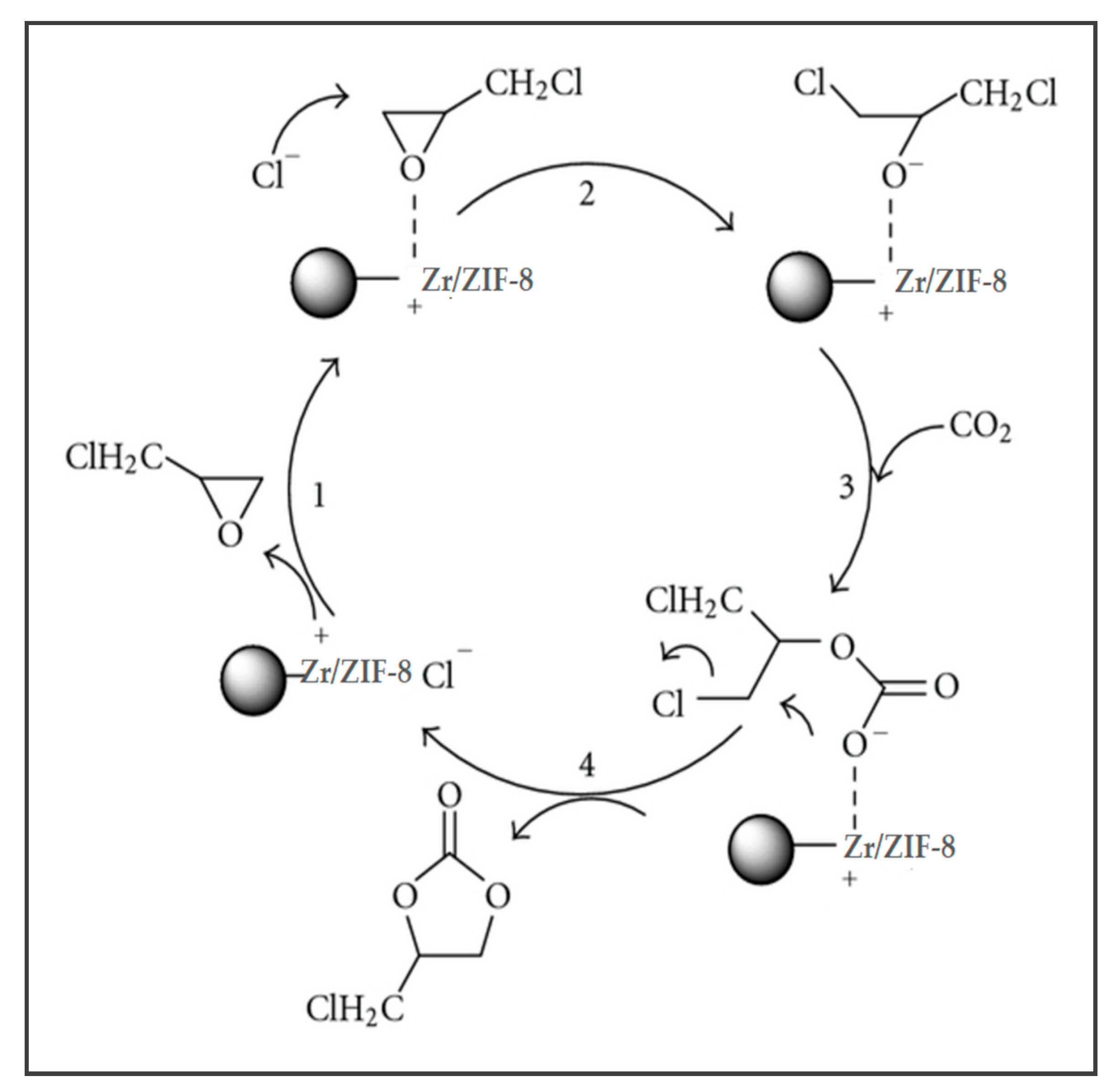
Figure 1. Proposed reaction mechanism for cycloaddition reaction of epichlorohydrin (ECH) and carbon dioxide (CO2).
Energies 13 00741 g001
Figure 2. Reaction pathways for cycloaddition reaction of ECH and CO2.
Energies 13 00741 g002
Figure 3. Predicted versus actual values models for (a) ECH conversion and (b) chloromethyl ethylene carbonate (CMEC) yield.
Energies 13 00741 g003
Figure 4. Normal plot of residuals for (a) ECH conversion and (b) CMEC yield.
Energies 13 00741 g004
Figure 5. The plot of residuals versus predicted response for (a) ECH conversion and (b) CMEC yield.
Energies 13 00741 g005
Figure 6. The plot showing the effect reaction of temperature on CMEC yield.
Energies 13 00741 g006
Figure 7. The plot showing the effect of CO2 pressure on CMEC yield.
Energies 13 00741 g007
Figure 8. The plot showing the effect of reaction time on CMEC yield.
Energies 13 00741 g008
Figure 9. The plot showing the effect of catalyst loading on CMEC yield.
Energies 13 00741 g009
Figure 10. (a) 3D response surface of the effect of temperature and pressure on CMEC yield. (b) Contour plot of the effect of temperature and pressure on CMEC yield.
Energies 13 00741 g010
Figure 11. (a) 3D response surface of the effect of reaction time and temperature on CMEC yield. (b) Contour plot of the effect of reaction time and temperature on CMEC yield.
Energies 13 00741 g011
Figure 12. (a) 3D response surface of the effect of temperature and catalyst loading on CMEC yield. (b) Contour plot of the effect of temperature and catalyst loading on CMEC yield.
Energies 13 00741 g012
Figure 13. (a) 3D response surface of the effect of reaction time and pressure on CMEC yield. (b) Contour plot of the effect of reaction time and pressure on CMEC yield.
Energies 13 00741 g013
Figure 14. (a) 3D response surface of the effect of reaction time and catalyst loading on CMEC yield. (b) Contour plot of the effect of reaction time and catalyst loading on CMEC yield.
Energies 13 00741 g014
Figure 15. (a) 3D response surface of the effect of catalyst loading and pressure on CMEC yield. (b) Contour plot of the effect of catalyst loading and pressure on CMEC yield.
Energies 13 00741 g015
Figure 16. Catalyst reusability studies of Zr/ZIF-8 on conversion of ECH, and CMEC yield using predicted response surface methodology’s optimum condition of catalyst loading 12% (w/w); reaction temperature 353 K; CO2 pressure 11 bar, reaction time 12 h, stirring speed 350 rpm.
Energies 13 00741 g016
Table 1. Experimental design variables and their coded levels.
VariablesCodeRange and Levels
−10+1
Temperature (K)x1313353373
Pressure (bar)x24816
Catalyst loading (w/w)x35715
Time (h)x44816
Table 2. Experimental design matrix with the actual and predicted responses.
RunT
x1
(K)
P
x2
(bar)
t
x3
(h)
Catalyst Loading
x4
(w/w)
Actual ECH Conv. (%)Predicted ECH Conv. (%)Actual CMEC Yield (%)Predicted CMEC Yield (%)
13134874246.331614.63
235381656768.173332.29
33538878484.006464.00
4313161675859.882931.67
53538878484.006464.00
63538455255.672626.46
735341677572.964041.04
83138855455.792324.88
9353161679393.296566.04
1031388155856.463130.38
1135316858681.213635.00
1237316878681.674546.13
1337348157582.335457.63
14353168158891.386868.00
153738476862.383833.33
163538878484.006464.00
17373816159085.386460.67
1837316855459.292628.88
1931316879082.675551.13
2037388158687.966464.38
213534476864.463536.21
2235388158484.006464.00
233538878484.006464.00
24353164157075.793536.21
2531384155252.882324.33
26353816158985.336564.29
273534856658.883733.50
2835348157778.044443.00
2937384156967.833535.46
Table 3. Analysis of variance (ANOVA) of developed model for ECH conversion.
SourceSum of SquareDiff.Mean SquareF Valuep-ValueSignificance
Model5014.0914362.0111.21<0.0001HS
x1-temperature827.751827.7526.020.0001HS
x2-pressure854.081854.0827.10<0.0001HS
x3-catalyst loading871.331871.3318.680.0006HS
x4-reaction time619.001619.0021.580.0005HS
x1x2308.251308.259.440.0060HS
x1x3177.001177.004.980.0283S
x1x458.00158.001.950.1842NS
x2x318.25118.250.620.4451NS
x2x438.25138.251.290.2754NS
x3x45.1515.150.190.6691NS
x12789.391789.3925.730.0001HS
x224.1614.160.150.7030NS
x32353.821353.8211.130.0049S
x42336.951336.959.400.0061S
Residual448.081434.86
Lack of Fit448.081044.810.440.56NS
Pure Error0.00040.000
Cor Total5553.1728
S: Significant. NS: Not significant. HS: Highly significant.
Table 4. Analysis of variance (ANOVA) of developed model for CMEC yield.
Sum of SquareDifferenceMean SquareF Valuep-ValueSignificance
Model7335.5514431.9068.68<0.0001HS
x1-temperature1023.0011023.00139.85<0.0001HS
x2-pressure468.751468.7560.53<0.0001HS
x3-catalyst loading1260.7511260.75162.80<0.0001HS
x4-time901.331901.33116.39<0.0001HS
x1x2576.001576.0074.38<0.0001HS
x1x3225.001225.0029.05<0.0001HS
x1x4100.001100.0012.910.0029HS
x2x3119.001119.0015.620.0014HS
x2x4146.251146.2520.180.0005HS
x3x4128.251128.2517.080.0010HS
x121258.7811258.78176.11<0.0001HS
x22347.291347.2942.52<0.0001HS
x32897.341897.34128.27<0.0001HS
x42897.051897.05120.62<0.0001HS
Residual104.24147.87
Lack of Fit104.241010.431.350.325NS
Pure Error0.00040.000
Cor Total7444.7928
S: Significant. NS: Not significant. HS: Highly significant.
Table 5. Optimization constraints used to predict optimum conditions for chloromethyl ethylene carbonate synthesis.
FactorCodeGoalLimits
LowerUpper
Temperature (K)x1Minimize313373
Pressure (bar)x2In range216
Catalyst loading (%)x3In range515
Time (h)x4Minimize216
ECH conversionY1Maximize6093
CMEC yieldY2Maximize3068